EP4022650B1 - Schmelzbrennstoffreaktoren und öffnungsringplatten für schmelzbrennstoffreaktoren - Google Patents
Schmelzbrennstoffreaktoren und öffnungsringplatten für schmelzbrennstoffreaktoren Download PDFInfo
- Publication number
- EP4022650B1 EP4022650B1 EP20875650.2A EP20875650A EP4022650B1 EP 4022650 B1 EP4022650 B1 EP 4022650B1 EP 20875650 A EP20875650 A EP 20875650A EP 4022650 B1 EP4022650 B1 EP 4022650B1
- Authority
- EP
- European Patent Office
- Prior art keywords
- reactor
- orifice ring
- ring plate
- flow
- inlet
- Prior art date
- Legal status (The legal status is an assumption and is not a legal conclusion. Google has not performed a legal analysis and makes no representation as to the accuracy of the status listed.)
- Active
Links
Images


Classifications
-
- G—PHYSICS
- G21—NUCLEAR PHYSICS; NUCLEAR ENGINEERING
- G21C—NUCLEAR REACTORS
- G21C1/00—Reactor types
- G21C1/04—Thermal reactors ; Epithermal reactors
- G21C1/06—Heterogeneous reactors, i.e. in which fuel and moderator are separated
- G21C1/22—Heterogeneous reactors, i.e. in which fuel and moderator are separated using liquid or gaseous fuel
-
- G—PHYSICS
- G21—NUCLEAR PHYSICS; NUCLEAR ENGINEERING
- G21C—NUCLEAR REACTORS
- G21C1/00—Reactor types
- G21C1/04—Thermal reactors ; Epithermal reactors
- G21C1/06—Heterogeneous reactors, i.e. in which fuel and moderator are separated
- G21C1/14—Heterogeneous reactors, i.e. in which fuel and moderator are separated moderator being substantially not pressurised, e.g. swimming-pool reactor
-
- G—PHYSICS
- G21—NUCLEAR PHYSICS; NUCLEAR ENGINEERING
- G21C—NUCLEAR REACTORS
- G21C11/00—Shielding structurally associated with the reactor
- G21C11/06—Reflecting shields, i.e. for minimising loss of neutrons
-
- G—PHYSICS
- G21—NUCLEAR PHYSICS; NUCLEAR ENGINEERING
- G21C—NUCLEAR REACTORS
- G21C15/00—Cooling arrangements within the pressure vessel containing the core; Selection of specific coolants
- G21C15/24—Promoting flow of the coolant
-
- G—PHYSICS
- G21—NUCLEAR PHYSICS; NUCLEAR ENGINEERING
- G21C—NUCLEAR REACTORS
- G21C5/00—Moderator or core structure; Selection of materials for use as moderator
- G21C5/14—Moderator or core structure; Selection of materials for use as moderator characterised by shape
-
- G—PHYSICS
- G21—NUCLEAR PHYSICS; NUCLEAR ENGINEERING
- G21C—NUCLEAR REACTORS
- G21C5/00—Moderator or core structure; Selection of materials for use as moderator
- G21C5/18—Moderator or core structure; Selection of materials for use as moderator characterised by the provision of more than one active zone
- G21C5/22—Moderator or core structure; Selection of materials for use as moderator characterised by the provision of more than one active zone wherein one zone is a superheating zone
-
- G—PHYSICS
- G21—NUCLEAR PHYSICS; NUCLEAR ENGINEERING
- G21C—NUCLEAR REACTORS
- G21C15/00—Cooling arrangements within the pressure vessel containing the core; Selection of specific coolants
- G21C15/02—Arrangements or disposition of passages in which heat is transferred to the coolant; Coolant flow control devices
-
- Y—GENERAL TAGGING OF NEW TECHNOLOGICAL DEVELOPMENTS; GENERAL TAGGING OF CROSS-SECTIONAL TECHNOLOGIES SPANNING OVER SEVERAL SECTIONS OF THE IPC; TECHNICAL SUBJECTS COVERED BY FORMER USPC CROSS-REFERENCE ART COLLECTIONS [XRACs] AND DIGESTS
- Y02—TECHNOLOGIES OR APPLICATIONS FOR MITIGATION OR ADAPTATION AGAINST CLIMATE CHANGE
- Y02E—REDUCTION OF GREENHOUSE GAS [GHG] EMISSIONS, RELATED TO ENERGY GENERATION, TRANSMISSION OR DISTRIBUTION
- Y02E30/00—Energy generation of nuclear origin
- Y02E30/30—Nuclear fission reactors
Definitions
- molten fuel reactors generally provide higher average core power densities compared to solid fuel reactors, while at the same time having reduced fuel costs due to the relatively high cost of solid fuel fabrication.
- Molten fluoride fuel salts suitable for use in nuclear reactors have been developed using uranium tetrafluoride (UF 4 ) mixed with other fluoride salts as well as using fluoride salts of thorium.
- Molten fluoride salt reactors have been operated at average temperatures between 600 °C and 860 °C.
- Binary, ternary, and quaternary chloride fuel salts of uranium, as well as other fissionable elements, have been described in co-assigned U.S. Patent Application Serial No. 14/981,512 , titled MOLTEN NUCLEAR FUEL SALTS AND RELATED SYSTEMS AND METHODS.
- the application further discloses fuel salts with modified amounts of 37 Cl, bromide fuel salts such as UBr 3 or UBr 4 , thorium chloride fuel salts, and methods and systems for using the fuel salts in a molten fuel reactor.
- Average operating temperatures of chloride salt reactors are anticipated between 300 °C and 800 °C, but could be even higher, e.g., > 1000 °C.
- US 2018/137944 discloses various configurations and components of a molten fuel fast or thermal nuclear reactor for managing the operating temperature in the reactor core.
- US 3743577 discloses a single fluid molten salt nuclear breeder reactor.
- the orifice ring plate is disposed within a low power region of a reactor core and proximate inlet channels that channel fuel salt into the reactor core.
- the orifice ring plate is oriented substantially orthogonal to the flow of fuel salt and is configured to balance and distribute the flow of fuel salt that enters into an active core region.
- the orifice ring plate is coaxial with the right-circular cylinder shaped reactor core and is configured to direct fuel salt along the sides of the reactor core, direct fuel salt through the plate to provide flow distribution in the azimuthal direction, and allow fuel salt to flow below the plate to reduce or prevent centerline recirculation in the reactor core.
- This disclosure describes molten fuel reactors and orifice ring plates for molten fuel reactors.
- the orifice ring plate is disposed within a low power region of a reactor core and proximate inlet channels that channel fuel salt into the reactor core.
- the orifice ring plate is oriented substantially orthogonal to the flow of fuel salt and is configured to balance and distribute the flow of fuel salt that enters into an active core region.
- the orifice ring plate is coaxial with the right-circular cylinder shaped reactor core.
- the orifice ring plate has a top solid portion that acts a deflector vane to direct fuel salt along side reflectors that define the reactor core and to reduce or prevent reflector recirculation.
- One or more apertures are formed within the plate that allow fuel salt to flow through the plate and provide flow distribution in the azimuthal direction within the reactor core.
- the plate is configured to allow fuel salt to flow below the plate to reduce or prevent centerline recirculation in the reactor core and support fuel salt drainage from the inlet channel.
- a height of the orifice ring plate is approximately equal to a height of the inlet channel.
- an inside lower corner of the side reflectors that form a boundary between the inlet channel and the reactor core is curved so that fuel salt can flow above the orifice ring plate.
- a radius of the curved corner is about one-third of the height of the inlet channel.
- the orifice ring plate is spaced from the inlet channel so that fuel salt flow between multiple inlet channels can be balanced upstream of the plate.
- the terms “axial” and “longitudinal” refer to directions and orientations, which extend substantially parallel to a centerline of the reactor core and the orifice ring plate.
- the terms “radial” and “radially” refer to directions and orientations, which extend substantially perpendicular to the centerline of the reactor core and the orifice ring plate.
- the term “circumferential” and “circumferentially” refer to directions and orientations, which extend arcuately about the centerline of the reactor core and the orifice ring plate.
- molten fuel nuclear reactor This disclosure describes various configurations and components of a molten fuel nuclear reactor.
- examples of a molten fuel reactor that use a chloride fuel will be described.
- any type of fuel salt now known or later developed, may be used and that the technologies described herein may be equally applicable regardless of the type of fuel used, such as, for example, salts having one or more of U, Pu, Th, or any other actinide.
- the minimum and maximum operational temperatures of fuel within a reactor may vary depending on the fuel salt used in order to maintain the salt within the liquid phase throughout the reactor. Minimum temperatures may be as low as 300-350 °C and maximum temperatures may be as high as 1400 °C or higher.
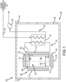
- FIG. 1 illustrates, in a block diagram form, some of the basic components of a molten fuel reactor 100.
- the molten fuel reactor 100 includes a reactor core 102 containing a fissionable fuel salt 104 that is liquid at the operating temperature.
- Fissionable fuel salts include salts of any nuclide capable of undergoing fission when exposed to low-energy thermal neutrons or high-energy neutrons.
- fissionable material includes any fissile material, any fertile material or combination of fissile and fertile materials.
- the fuel salt 104 may or may not completely fill the core 102, and the example shown is illustrated with an optional headspace 106 above the level of the fuel salt 104 in the core 102.
- the size of the reactor core 102 may be selected based on the characteristics and type of the particular fuel salt 104 being used in order to achieve and maintain the fuel in an ongoing state of criticality, during which the heat generated by the ongoing production of neutrons in the fuel causes the temperature of the molten fuel to rise when it is in the reactor core 102.
- the performance of the reactor 100 is improved by providing one or more reflectors 108 around the core 102 to reflect neutrons back into the core.
- the reactor 100 may include an upper reflector 110, a lower reflector 112, and at least one radial side reflector 114. Additionally, the reflectors 108 may shield components positioned radially outward from the core 102.
- the molten fuel salt 104 is circulated in a fuel loop 116 between the reactor core 102 and one or more primary heat exchangers 118 located outside of the core 102. The circulation may be performed using one or more pumps 120.
- the primary heat exchangers 118 transfer heat from the molten fuel salt 104 to a primary coolant 122 that is circulated through a primary coolant loop 124.
- the primary coolant may be another salt, such as NaCl-MgCh, lead, or other liquid metal.
- Other coolants are also possible including Na, NaK, Na mixtures, supercritical CO 2 , liquid lead, and lead bismuth eutectic.
- the radial side reflector 114 extends between the upper reflector 110 and the lower reflector 112 and is positioned between each primary heat exchanger 118 and the reactor core 102 as shown in FIG. 1 .
- the reactor core 102 has substantially a right-circular cylinder shape with a diameter of 2 meters (m) and a height of 3 m or greater, and is oriented vertically along a longitudinal axis 126 so that the flat ends of the cylinder are on the top and bottom, and adjacent the upper reflector 110 and the lower reflector 112, respectively.
- the radial side reflectors 114 are substantially parallel to the longitudinal axis 126 and at least partially define an inner diameter 128 of the reactor core 102.
- the entire reactor core 102 is surrounded by reflectors 108 between which are provided radial channels for a flow of fuel salt 104 into (e.g., inlet channels 130) and out (e.g., outlet channels 132) of the reactor core 102.
- eight side reflectors 114 and primary heat exchangers 118 are circumferentially spaced around the reactor core 102 and about the longitudinal axis 126, with each primary heat exchanger 118 provided with the pump 120 to drive circulation of the fuel salt 104 and generate the fuel loop 116.
- a different number of side reflectors 114 and primary heat exchangers 118 may be used as required or desired.
- examples having 2, 3, 4, 5, 6, 8, 12, and 16 reflectors and primary heat exchangers are contemplated.
- circulation of the fuel salt 104 may be naturally driven (e.g., fuel circulation via the density differential created by the temperature differences within the fuel loop). This configuration can obviate the need for fuel salt pumps 120.
- the inlet channel 130 is shown adjacent the lower reflector 112 in FIG. 1 , the fuel loop 116 can be reversed and the inlet channel 130 can be adjacent the upper reflector 110 as required or desired.
- the fuel salt 104 in normal (power generating) operation, is pumped from the reactor core 102, through the primary heat exchanger 118, and cooled fuel salt 104 is returned back to reactor core 102. Heated primary coolant 122 from the primary heat exchangers 118 is passed to a power generation system 134 for the generation of some form of power, e.g., thermal, electrical or mechanical.
- the reactor core 102, primary heat exchangers 118, pumps 120, molten fuel circulation piping (including other ancillary components that are not shown such as check valves, shutoff valves, flanges, drain tanks, etc.) and any other components through which the molten fuel circulates or contacts during operation can be referred to as the fuel loop 116.
- the primary coolant loop 124 includes those components through which primary coolant circulates, including the primary heat exchangers 118, primary coolant circulation piping (including other ancillary components that are not shown such as coolant pumps 136, check valves, shutoff valves, isolation valves, flanges, drain tanks, etc.).
- Salt-facing elements of the molten fuel reactor may be formed and/or clad to protect against corrosion.
- Other protection options include protective coatings, loose fitting liners, or press-fit liners.
- any suitable high temperature and corrosion resistant steel such as, but not limited to, 316 stainless, HT-9, a molybdenum alloy, a zirconium alloy (e.g., ZIRCALOY TM ), SiC, graphite, a niobium alloy, nickel or alloy thereof (e.g., HASTELLOY TM ), or high temperature ferritic, martensitic, stainless steel, or the like, may be used.
- the molten fuel reactor 100 further includes at least one containment vessel 138 that contains the fuel loop 116 to prevent a release of molten fuel salt 104 in case there is a leak from one of the fuel loop components.
- the containment vessel 138 is often made of two components: a lower, vessel portion 140 that takes the form of a unitary, open-topped vessel with no penetrations of any kind; and an upper, cap portion 142 referred to as the vessel head that covers the top of the vessel portion 140. All points of access to the reactor 100 are from the top through the vessel head 142.
- this disclosure describes multiple alterations and component configurations that improve the performance of the reactor 100 described with reference to FIG. 1 .
- the flow of fuel salt 104 within the fuel loop 116 enters the reactor core 102 from the inlet channel 130, the flow turns sharply (e.g., approximately 90°) to flow in an upward direction through the core 102.
- This change of direction of the flow of fuel salt 104 and the relative cross-section of the incoming channels as compared to the diameter of the core region can induce formation of jet-like flow recirculation vortexes and flow behavior that reduces performance of the molten fuel reactor 100.
- these recirculation vortexes result in relatively stationary flow within the middle of the vortex that heats up, and via buoyancy, the fuel salt can move through the reactor core and induce unstable flow and possibly reactivity instabilities within the fuel loop 116.
- these vortexes can be formed along an inside wall of the side reflector 114 and proximate the lower corner with the inlet channel 130.
- the shape and size of the reactor core and the inlet channel has been modified to reduce the sharp corners in the fuel loop.
- the reactor core can take on a more hourglass shape with a modified inlet channel.
- These reactor cores increase the volume of the reactor core, which then requires more fuel salt.
- a horizontal plate e.g. in relation to the longitudinal axis
- This plate is positioned close to the active core and absorbs a large amount of neutrons, and thereby also increases the amount of fuel salt required.
- a flow conditioner as described further below is disposed within the reactor core 102 and proximate the inlet channels 130 within a low power region of the core.
- the flow conditioner ensures the fuel salt flows entering the active core are well-distributed, without jet-like behavior or major recirculations, as the flow turns the corner inside the lower edge of the reflector 108.
- the flow conditioner is an orifice ring pate designed to optimize the flow, and thus, the heat distribution of the fuel salt 104 as it flows through the core.
- the flow conditioner may take an alternative form such as directional baffles, tube bundles, honeycombs, porous materials, and the like. The flow conditioner also reduces the impact of reactor geometry so that the volume of fuel salt needed for operation is not increased.
- the molten fuel reactor 100 described in FIG. 1 can take many different forms.
- the reactor 100 can be a molten chloride fast reactor that is used to generate power as described above.
- the reactor 100 can be a reactor that does not generate power and that only generates heat. This reactor can be utilized to study the fuel salt 104 as required or desired.
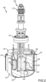
- FIG. 2 is a perspective sectional view of one possible physical implementation of a reactor core system 200.
- the reactor core system 200 includes a single molten salt pump assembly 202 to circulate fuel salt through a central active core 204 and into four individual flow channels 206 that define a flow loop 208 of fuel salt.
- the flow loop 208 is described in further detail in FIG. 3 below.
- the pump assembly 202 includes a pump motor 210, a pump flange 212, and a pump impeller 214. Rotation of the impeller 214 drives the flow of fuel salt upward through the core 204 and downward within the flow channels 206 and along an interior surface of a reactor vessel 216.
- the flow direction may be reversed as required or desired.
- the reactor vessel 216 can include fins 218 on the exterior surface to assist in transferring heat from the reactor vessel 216. As such, in this example a primary coolant loop is not provided and power is not generated from the reactor core system 200.
- one or more reflectors surround the active core 204.
- a lower reflector 220 is disposed on the bottom side of the core 204 and one or more side reflectors 222 surround the lateral sides of the core 204.
- a vessel head 224 acts as a reflector at the top side of the core 204.
- an upper reflector may be disposed adjacent the vessel head 224.
- the reactor core system 200 also includes one or more independently rotated control drums 226. In this example, there are four control drums 226 that are cylinders of a reflector material with a partial face made of a neutron absorber 228.
- the side reflectors 222 define a receiving space for each control drum 226 so that the control drums 226 can be inserted into the reactor vessel 216 adjacent the active core 204.
- the control drums 226 can be independently rotated within the reflector 222 so that the neutron absorber 228 is closer to or farther away from the active core 204. This controls the amount of neutrons that are reflected back into the core 204, and thus, available for fission.
- the absorber 228 is rotated to be in proximity to the core 204, neutrons are absorbed rather than reflected and the reactivity of the reactor is reduced.
- the reactor may be maintained in a state of criticality, subcriticality, or supercriticality, as required or desired.
- an orifice ring plate 230 is disposed within the active core 204 and proximate the inlet flow of fuel salt from the flow channels 206, adjacent the lower reflector 220.
- the orifice ring plate 230 is configured to condition the flow of fuel salt entering the active core 204 so as to reduce or eliminate fuel salt flow recirculation inside the lower active core region.
- the orifice ring plate 230 is described in further detail below.
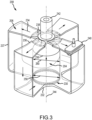
- FIG. 3 is a perspective view of the fuel salt flow loop 208 of the reactor core system 200 (shown in FIG. 2 ).
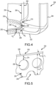
- FIG. 4 is an enlarged partial perspective view of the exemplary orifice ring plate 230 and an inlet channel 232 of the fuel salt flow loop 208.
- FIG. 5 is an enlarged partial perspective view of the orifice ring plate 230.
- the flow loop 208 is full of fuel salt and the flow direction is illustrated by arrows 234.
- the flow loop 208 is defined by the active core 204, which is substantially a right-circular cylinder shape, and the flow channels 206 that are formed around the side reflectors 222 (shown in FIG. 2 ).
- each of the four flow channels 206 are circumferentially spaced around the active core 204, and include a radially extending inlet channel 232 configured to channel fuel salt into a lower portion of the active core 204 and a radially extending outlet channel 236 configured to channel fuel salt out of an upper portion of the active core 204.
- Each inlet channel 232 and outlet channel 236 are coupled in flow communication with an axial channel 237 that is substantially parallel to the active core 204, but separated from the core by one or more of the reflectors (not shown).
- each of the four flow channels 206 are discrete and spaced apart from one another. It should be appreciated that any other number of discrete flow channels can be utilized as required or desired.
- each of the flow channels 206 may be coupled in flow communication with each other so that the fuel salt flow can be balanced prior to entering the active core 204.
- the fuel salt flow loop 208 may include a single flow channel that extends approximately 360° around the active core 204 so that the fuel salt flow can be balanced prior to entering the core. Upstream of the outlet channel 236 directing vanes 238 are provided so as to condition the fuel salt flow coming out of the pump assembly 202 (shown in FIG. 2 ).
- a flow restriction device 240 configured to control the flow of fuel salt may be located in one or more of the flow channels 206. As illustrated in FIG. 3 , the flow restriction device 240 is located at the top of one of the four fuel salt flow channels 206 between the active core 204 and the reactor vessel. Although only one flow restriction device 240 is shown, in alternative examples, some of the other, or all of the other, flow channels 206 may be furnished with such devices.
- the flow restriction device 240 can include a valve, a gate valve, sluice gate, pinch valve, or the like, and allows the flow rate of the fuel salt to be reduced with the channel 206. Additionally, an expansion volume 242 is provided for the fuel salt at least partially within the pump assembly 202.
- the expansion volume 242 allows heated fuel salt to expand and enter the volume during reactor operation.
- the volume 242 can be filled with an inert gas and have a cover gas management system (not shown) to control the pressure of the gas within the expansion volume 242 and clean the gas as required or desired.
- the orifice ring plate 230 is disposed within the active core 204 and proximate the inlet channels 232.
- the orifice ring plate 230 extends circumferentially about a longitudinal axis 244 of the active core 204 and includes a top end 246 and a bottom end 248.
- the orifice ring plate 230 can be circular or substantially circular, whereby the ring plate 230 is formed from a plurality of linear sections that when coupled together form a ring like shape.
- an axial axis of the orifice ring plate 230 aligns with the longitudinal axis 244 of the active core 204 so that the core 204 and the plate 230 are coaxial.
- the top end 246 and the bottom end 248 extend is a direction along the longitudinal axis 244 such that the orifice ring plate 230 is substantially parallel to the longitudinal axis 244 of the active core 204.
- the top end 246 and the bottom end 248 define a height H 1 of the orifice ring plate 230.
- the orifice ring plate 230 has a plurality of first apertures 250 that are configured to allow a flow of fuel salt through the plate, and the greater number of apertures 250 the more fuel salt is allowed to flow through the plate.
- the first apertures 250 are circumferentially spaced around the orifice ring plate 230 and extend in a radial direction relative to the longitudinal axis 244. In an aspect, the apertures 250 are spaced approximately every 4°.
- the first apertures 250 are substantially circular in shape, however, it is appreciated that the shape of the apertures can have any other shape (e.g., oval, rectangular, etc.) that enables the orifice ring plate 230 to function as described herein.
- the orifice ring plate 230 is downstream of the inlet channel 232 and at least partially covers the inlet channel 232 with respect to the active core 204.
- the bottom end 248 of the orifice ring plate 230 is directly adjacent the lower reflector 220 (shown in FIG. 2 ).
- the bottom end 248 of the orifice ring plate 230 may be offset and raised above the lower reflector 220 so that a gap is formed between the bottom end 248 and the lower reflector 220.
- the orifice ring plate 230 has an inner radial surface 252 and an opposite outer radial surface 254. The outer radial surface 254 faces the inlet channel 232.
- the inner radial surface 252 is axially aligned with an inner circumferential perimeter 256 of the active core 204 formed by the reflectors. That is, the inner radial surface 252 has a diameter 258 that is approximately equal to an inner diameter 260 of the core 204.
- the inner diameter 260 of the core 204 is formed at least partially by the side reflectors 222 (shown in FIG. 2 ). Because the orifice ring plate 230 has a thickness Ti, the diameter of the outer radial surface 254 is greater than the inner diameter 260 of the core 204.
- the inlet channels 232 and the outlet channels 236 extend in a radial direction relative to the longitudinal axis 244 of the active core 204.
- the inlet channels 232 are radially offset 262 from the circumferential perimeter 256 of the active core 204.
- an upstream gap 264 in the radial direction is formed between the inlet channel 232 and the outer radial surface 254 of the orifice ring plate 230.
- the gap 264 enables each of the inlet channels 232 to be in flow communication with each other upstream of the orifice ring plate 230 and increase flow distribution around the perimeter 256 of the active core 204.
- the inlet channel 232 has a perimeter 266 at the active core 204.
- the perimeter 266 has a height H 2 and a width W 2 .
- the height H 1 of the orifice ring plate 230 is approximately equal to the height H 2 of the inlet channel 232.
- This size and shape of the orifice ring plate 230 would generally completely cover the inlet channel 232, however, an intersection edge 268 of the inlet channel 232 and the active core 204 is rounded and has a radius 270.
- the side reflectors 222 defines the boundary of the flow loop 208 between the inlet channel 232 and the active core 204. As such, the side reflectors 222 have a lower inside corner 272 (shown in FIG.
- an aspect ratio (e.g., the ratio of width to height) of the inlet channel 232 at least partially defines the radius 270.
- the radius 270 may be about one-third of the height H 2 of the inlet channel 232.
- the inlet channel 232 is relatively narrow (e.g., the width W 2 greater than the height H 2 ), and as such, the radius 270 is greater than one-third of the height H 2 so that the rounding radius of edge 268 is increased.
- the position of the orifice ring plate 230 enables the fuel salt exiting the inlet channel 232 to flow above the plate 230, through the plate 230 via the first apertures 250, and below the plate 230 in order to enter the active core 204.
- the first apertures 250 are offset from the top end 246 of the orifice ring plate 230 such that a solid portion 274 is formed.
- the solid portion 274 induces at least a portion of the fuel salt to flow above the orifice ring plate 230, and the larger the solid portion 274 the more flow is directed above the plate 230.
- the bottom end 248 has a plurality of second apertures 276 that are partially defined in the plate 230 and that are configured to allow fuel salt to flow under the bottom of the plate.
- the second apertures 276 are circumferentially spaced around the orifice ring plate 230 and extend in a radial direction relative to the longitudinal axis 244.
- the second apertures 276 are substantially semi-circular in shape, however, it is appreciated that the shape of the apertures can have any other shape (e.g., oval, rectangular, etc.) that enables the orifice ring plate 230 to function as described herein.
- the first apertures 250 form a row of apertures with a centerline positioned along the height H 1 of the plate 230.
- the first apertures 250 are similarly sized and shaped and are equally circumferentially spaced.
- the second apertures 276 also form a row of apertures with a centerline positioned along the height H 1 of the plate 230 but offset from the row of first apertures 250 so that they do not axially overlap.
- the second apertures 276 are similarly sized and shaped and are equally circumferentially spaced.
- the row of first apertures 250 are circumferentially offset from the row of second apertures 276 so that the first apertures 250 are positioned between the second apertures 276 and vice-versa.
- the apertures 250, 276 may have different sizes and/or shapes as required or desired.
- the apertures 250, 276 may also have different dimensions (e.g., diameter for a circular apertures) as needed in either the circumferential and/or axial directions of the orifice ring plate 230 so as to provide the desired flow distribution corrections for target conditions of interest.
- FIG. 6 is a fuel salt flow vector plot for the fuel salt flow loop 208 shown in FIG. 4 .
- FIG. 7 is a fuel salt flow vector and temperature plot for the fuel salt flow loop 208 shown in FIG. 3 .
- the orifice ring plate 230 enables fuel salt flow to be balanced and distributed when entering the active core 204 so as to increase reactor performance. For example, a portion of the flow is directed in an upwards direction from the inlet channel 232 and reduces or prevents flow recirculation along the inner perimeter 256 of the active core 204.
- a portion of the flow is channeled through the orifice ring plate 230 to distribute flow in the azimuthal direction. Additionally, a portion of the flow is channeled under the orifice ring plate 230 to reduce or prevent recirculation proximate the centerline of the active core 204.
- the vector plot illustrates fuel salt flow velocity through the orifice ring plate 230.
- the orifice ring plate 230 enables fuel salt to pass through the plate 230 (e.g., via apertures 250) so as to provide flow distribution in the azimuthal direction, enables fuel salt to go over the plate 230 and up the reflector wall to reduce or prevent flow recirculation, and enable fuel salt to go below the plate 230 to reduce or prevent centerline recirculation and enable fuel salt drainage from the inlet channel 232.
- the largest flow velocity of the fuel salt is retained by going over the top of the orifice ring plate 230.
- the reactor modeled has a flow velocity of fuel salt that is considered to be low and is generally around 1 meter/second. Because of the low flow velocity, more flow is directed through the orifice ring plate 230 since flow recirculations are not very large.
- the fuel salt flow velocity upstream and downstream of the orifice ring plate 230 is substantially maintained.
- the pressure drop across the orifice ring plate 230 is less than or equal to approximately 10 kilopascal (kPa). In other examples, the pressure drop is less than or equal to approximately 25 kPa.
- pressure drop across the orifice ring plate 230 is between about 5-10% of the overall fuel salt flow loop pressure.
- the orifice ring plate 230 as described herein enables a variety of parameters (e.g., height, size of apertures, aperture spacing, solid portion sizes, etc.) to be tuned so that the plate 230 can increase performance of the reactor.
- the vector plot illustrates fuel salt flow velocity through the entire flow loop 208, and the orifice ring plate 230 enables the fuel salt to maintain its velocity throughout the loop 208 more effectively because flow recirculations are reduced or prevented. For example, if there is not even pressure distribution within the core and there is increased flow pressure in the center, recirculations are induced at the sides of the core. Conversely, with increased flow pressure on the sides, recirculations are induced at the center of the core. Additionally, temperature distribution of the fuel salt within the active core 204 improves because flow recirculations are reduced or prevented. Accordingly, the orifice ring plate 230 improves performance of a molten fuel reactor.
- FIG. 8 is a partial perspective view of another orifice ring plate 300 and an inlet channel 302 of another fuel salt flow loop 304.
- the flow loop 304 includes a reactor core 306 that is substantially a right-circular cylinder shape with the inlet channel 302 proximate the bottom.
- the inlet channel 302 is connected to a channel 308 that includes a heat exchanger (not shown) and is on the opposite side of a reflector (now shown) from the reactor core 306.
- the flow loop 304 in this example has eight inlet channels 302 that channel fuel salt into the reactor core 306.
- the inlet channel 302 has an aspect ratio (e.g., width to height ratio) that is not as severe at the inlet channel described above in reference to FIGS.
- an edge 310 between the inlet channel 302 and the reactor core 306 has a radius 312 that is about one-third of the height of the inlet channel 302.
- the orifice ring plate 300 has a top end 314 that is formed with a solid portion and a bottom end 316 that has a plurality of second apertures 318 that are partially defined within the plate 300.
- the bottom end 316 of the plate 300 is raised above the lower reflector (not shown) by a longitudinal offset 320.
- This offset 320 allows more fuel salt to pass under the orifice ring plate 300 to avoid centerline recirculation and support drainage in higher flow velocities.
- a plurality of first apertures 322 are fully defined within the plate 300.
- the first apertures 322 are formed in two rows that are circumferentially offset from one another. By having two rows of apertures 322 more fuel salt can pass through the plate 300 to provide flow distribution in the reactor core 306.
- the configuration of the orifice ring plate 300 may be as follows. An original height of the plate 300 is set to be approximately equal to the height of the inlet channel 302 and four rows of apertures are sized within the plate 300. As such, the diameter of the apertures may be at least partially based on the height of the inlet channel 302. Then the top row of apertures are removed to form the solid portion at the top end 314. In this example, because of the larger flow rate of the fuel salt, the solid portion is larger than the examples described above so that more flow is directed up the sides of the reactor core 304 since recirculations are larger.
- the plate forming half of the apertures 318 is cut off, and this forms the offset 320 with a final height of the plate 300 being less than the height of the inlet channel 302.
- the plurality of first apertures 322 in the middle can be two rows of uniformly sized holes.
- the orifice ring plate 300 may be formed with multiple rows of apertures with decreasing size going up the rows from the bottom (e.g., largest apertures in the bottom row and smallest apertures in the top row), and in some examples, without including a raised gap at the bottom and an aperture free row at top.
- FIG. 9 is a partial perspective view of another orifice ring plate 400 and an inlet channel 402 of another fuel salt flow loop 404.
- the flow loop 404 includes a reactor core 406 that is substantially a right-circular cylinder shape with the inlet channel 402 proximate the top.
- the flow loop 404 is reversed when compared to the examples described above with the fuel salt being pumped downward through the reactor core 406, and the fuel salt exits the reactor core 406 at the bottom and enters from the top.
- the inlet channel 402 is disposed adjacent an upper reflector (not shown).
- the pump is disposed on the cold side of the flow loop 404 which increases pump efficiencies.
- the inlet channel 402 is connected to a channel 408 that includes a heat exchanger (not shown) and is on the opposite side of a reflector (now shown) from the reactor core 406.
- the flow loop 404 has eight inlet channels 402 that channel fuel salt into the reactor core 406.
- the inlet channel 402 has an aspect ratio (e.g., width to height ratio) that is not as severe at the inlet channel described above in reference to FIGS. 2-7 , however, fuel salt flow velocities are significantly higher (e.g., around 7 meters/second).
- an edge 410 between the inlet channel 402 and the reactor core 406 has a radius 412 that is about one-third of the height of the inlet channel 402.
- the orifice ring plate 400 has a top end 414 that has a plurality of second apertures 416 that are partially defined within the plate 400 and a bottom end 418 that is formed with a solid portion.
- the top end 414 of the plate 400 is lowered below the upper reflector (not shown) by a longitudinal offset 420.
- a plurality of first apertures 422 are fully defined within the plate 400.
- the first apertures 422 are formed in two rows that are circumferentially offset from one another.
- the orifice ring plate 400 increases fuel salt flow distribution in the reactor core 406 and reduces and/or prevents flow recirculation as described above.
- the orifice ring plate 400 counteracts the buoyant forces from fuel salt heating in an upwards directions.
- the size and spacing of the apertures 416, 422 can be different than the example described in FIG. 8 .
- a partial solid portion 424 may be formed on the top end 414 of the plate 400 between apertures 416. In some examples, the partial solid portion 424 may extend all the way to the upper reflector.
- the configuration of the orifice ring plate 400 with relating the sizes of the apertures 416, 422 to the height of the inlet channel 402 may be similar to the plate 300 described above in reference to FIG. 8 .
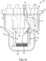
- FIG. 10 is an elevation view of another possible physical implementation of a reactor core system 500.
- the reactor core system 500 can be a demonstration reactor that is a nuclear reactor designed to allow for efficient testing and assessment of the reactor's design and technology or a commercial reactor as required or desired. Both demonstration and commercial reactors generate heat, however, the dissipation of the heat generated during operation includes the generation of useable power in commercial reactors, while the generation of useable power may or may not occur in demonstration reactors.
- the reactor core system 500 is a pool-type reactor having an enclosed vessel 502 with no bottom penetrations that contains reactor fuel salt 504, a fuel pump assembly 506, reflectors 508, heat exchangers 510, and control elements (not shown).
- the molten fuel salt 504 fills in all the space within the vessel 502 that is not taken up by components (e.g., reflectors 508, pump assembly 506, and heat exchangers 510), shielding, or fuel displacement elements.
- This forms a central 'active' critical core region 512 as well as fuel channels 514 connecting the active core 512 with the pump assembly 506 and heat exchangers 510.
- Reactor control elements enter through a vessel head 516 and are positioned within the radial reflector region surrounding the active core 512.
- Multiple fuel circuits operate in parallel to circulate the fuel salt 504, and in the event of a loss of forced flow, the reactor core system 500 is capable of retaining the fuel salt safely in the vessel 502 and removing decay heat via robust natural circulation.
- the critical, ⁇ active core' region 512 of the system 500 includes an open central, cylindrical chamber 518 defined by an annular draft tube 520 and a downcomer duct 522 defined outside of the draft tube 520 (e.g., between the draft tube 520 and the reflectors 508).
- the pump assembly 506 drives the fuel salt 504 upwardly out of the active core 512 and through the heat exchanger 510.
- a coolant flow 524 is channeled through an exchanger head 526 to extract heat from the active core 512.
- the fuel salt 504 exits from the bottom of the heat exchanger 510 and into the annular downcomer duct 522 between the draft tube 520 and the reflectors 508 re-entering the active core 512.
- the fuel salt 504 transitions around the bottom of the submerged draft tube 520 that separates the upward flowing fuel salt 504 within the chamber 518 from the downward flowing fuel salt 504 within the downcomer duct 522.
- an orifice ring plate 528 is disposed within the active core 512 and proximate the transition of the fuel salt 504 between the downcomer duct 522 and the chamber 518 of the active core 512.
- the orifice ring plate 528 is configured to condition the flow of fuel salt 504 moving around the bottom of the submerged draft tube 520 so as to reduce or eliminate fuel salt flow recirculation inside the lower active core region.
- the orifice ring plate 528 is described in further detail below.
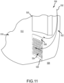
- FIG. 11 is a partial perspective view of a fuel salt flow loop 530 of the reactor core system 500 (shown in FIG. 10 ).
- the flow loop 530 is full of fuel salt and the flow direction is illustrated by arrows 532.
- the flow loop 530 is at least partially defined by the draft tube 520 and the reflectors 508.
- the fuel salt turns approximately 180° from the downcomer duct 522 to the chamber 518.
- the orifice ring plate 528 is disposed within the active core 512 proximate the bottom end of the draft tube 520.
- the orifice ring plate 528 has a plurality of apertures 534 arranged in rows configured to allow a flow of fuel salt through the plate and a top solid portion 536 that directs at least a portion of the fuel salt flow above the orifice ring plate 528. Additionally, the orifice ring plate 528 has a diameter that is less than a diameter of the draft tube 520 so that the orifice ring plate 528 is inwardly offset from the draft tube 520. A height of the orifice ring plate 528 is about equal to or less than the height of the bottom end of the draft tube 520 above the bottom reflector 508. The orifice ring plate 528 is coupled to and extends from the bottom of the core. In some example, a portion of the top of the orifice ring plate 528 may be supported by the draft tube 520 as required or desired.
- the orifice ring plate 528 enables the fuel salt flow 532 to be balance and distributed when entering the chamber 518 so as to increase reactor performance. For example, a portion of the flow is directed in an upwards direction along the inner surface of the draft tube 520 and reduces or prevents flow recirculation along the draft tube 520. A portion of the flow is channeled through the orifice ring plate 528 to distribute flow in the azimuthal direction. Additionally, a portion of the flow is channeled under the orifice ring plate 528 to reduce or prevent recirculation proximate the centerline of the active core 512.
- the spacing, sizing, and configuration of the apertures 534 and top solid portion 536 can be adjusted as described herein to balance and distribute the fuel salt flow.
- the orifice ring plate designs as described above.
- modifying one or more design parameters of the orifice ring plate for example, but not limited to, inner ring diameter, ring thickness, aperture diameter, aperture angular spacing, etc. can be done to tailor the orifice ring plate to specific reactor core designs and fuel salt flow velocities.
- the aperture size and spacing can be adjusted to tailor the amount of flow directed along the reflector wall.
- the size of the solid portion can also change the amount of flow directed along the reflector wall.
- the partial aperture size and spacing and/or the bottom offset can change the amount of flow directed underneath the plate and towards the centerline of the core.
- Aperture size and spacing also changes pressure drop and flow distribution within the core. For example, large diameter apertures enable more flow through the plate than smaller diameter apertures. Aperture sizes can be modified by location relative to the inlet channel (e.g., smaller diameters closer to the inlet channel and larger diameters farther away), and/or modified by location on the plate (e.g., smaller diameter at the bottom and larger diameters at the top). The thickness of the orifice ring plate can change the amount of pressure drop across the plate.
Landscapes
- Physics & Mathematics (AREA)
- Engineering & Computer Science (AREA)
- Plasma & Fusion (AREA)
- General Engineering & Computer Science (AREA)
- High Energy & Nuclear Physics (AREA)
- Monitoring And Testing Of Nuclear Reactors (AREA)
- Physical Or Chemical Processes And Apparatus (AREA)
- Structure Of Emergency Protection For Nuclear Reactors (AREA)
Claims (15)
- Schmelzbrennstoffreaktor (100), umfassend:einen Reaktorkern (200, 500), der wenigstens teilweise durch einen oberen Reflektor (110), einen unteren Reflektor (112) und wenigstens einen seitlichen Reflektor (114, 222) definiert ist, wobei der Reaktorkern im Wesentlichen die Form eines genau kreisförmigen Zylinders aufweist und wobei der Reaktorkern eine Längsachse (126) und einen Innendurchmesser (128) aufweist;wenigstens einen Einlass (130), der dazu ausgestaltet ist, Brennstoffsalz in den Reaktorkern einzuleiten;wenigstens einen Auslass (132), der dazu ausgestaltet ist, Brennstoffsalz aus dem Reaktorkern auszuleiten, wobei der wenigstens eine Einlass und der wenigstens eine Auslass wenigstens teilweise einen Strömungskreis (208) von Brennstoffsalz in Bezug auf den Reaktorkern definieren; undeine Lochringplatte (230), die innerhalb des Reaktorkerns und nahe dem wenigstens einen Einlass angeordnet ist, wobei die Lochringplatte dazu ausgestaltet ist, einen Brennstoffsalzstrom, der von dem wenigstens einen Einlass her in den Reaktorkern gelangt, zu konditionieren, wobei die Lochringplatte einen durchgehenden Ring ausbildet und sich in Umfangsrichtung um die Längsachse herum erstreckt und eine Höhe aufweist, die in einer Richtung entlang der Längsachse definiert ist, und wobei die Lochringplatte eine Mehrzahl radialer Öffnungen umfasst, die dazu ausgestaltet sind, den Brennstoffsalzstrom hindurchzulassen.
- Schmelzbrennstoffreaktor nach Anspruch 1, wobei die Lochringplatte eine Innenfläche aufweist, die mit dem Innendurchmesser des Reaktorkerns ausgerichtet ist.
- Schmelzbrennstoffreaktor nach einem vorangehenden Anspruch, wobei der wenigstens eine Einlass einen ersten Einlass und einen zweiten Einlass umfasst, wobei stromaufwärts der Lochringplatte ein Spalt (264) ausgebildet ist, sodass der erste Einlass und der zweite Einlass in Strömungsverbindung stehen.
- Schmelzbrennstoffreaktor nach einem vorangehenden Anspruch, wobei der wenigstens eine Einlass eine Höhe aufweist, die in der Längsachsenrichtung definiert ist, und wobei die Höhe der Lochringplatte ungefähr gleich der Höhe des wenigstens einen Einlasses ist.
- Schmelzbrennstoffreaktor nach einem vorangehenden Anspruch, wobei zwischen dem Reaktorkern und dem wenigstens einen Einlass (268) eine Kante definiert ist und wobei die Kante wenigstens teilweise abgerundet ist.
- Schmelzbrennstoffreaktor nach Anspruch 5, wobei der wenigstens eine Einlass eine Höhe aufweist, die in der Längsachsenrichtung definiert ist, und wobei ein Radius der Kante etwa ein Drittel der Höhe des wenigstens einen Einlasses beträgt.
- Schmelzbrennstoffreaktor nach einem vorangehenden Anspruch, wobei die Lochringplatte ein oberes Ende (246) und ein unteres Ende (248) umfasst, wobei das obere Ende einen massiven Abschnitt aufweist, sodass die Mehrzahl radialer Öffnungen gegenüber dem oberen Ende der Lochringplatte versetzt ist.
- Schmelzbrennstoffreaktor nach einem vorangehenden Anspruch, wobei die Lochringplatte ein oberes Ende (246) und ein unteres Ende (248) umfasst, wobei eine oder mehrere der Mehrzahl radialer Öffnungen teilweise in dem unteren Ende definiert sind.
- Schmelzbrennstoffreaktor nach Anspruch 8, wobei das untere Ende gegenüber dem unteren Reflektor versetzt ist.
- Schmelzbrennstoffreaktor nach einem vorangehenden Anspruch, wobei der wenigstens eine Einlass dem oberen Reflektor benachbart ist.
- Schmelzbrennstoffreaktor nach Anspruch 1, wobei:der wenigstens eine Einlass einer aus einer Mehrzahl radialer Einlässe ist, die dem unteren Reflektor benachbart und in Umfangsrichtung um die Längsachse herum beabstandet sind;der wenigstens eine Auslass einer aus einer Mehrzahl radialer Auslässe ist, die dem oberen Reflektor benachbart und in Umfangsrichtung um die Längsachse herum beabstandet sind, wobei der Brennstoffsalzströmungskreis durch den Reaktorkern in Bezug auf die Mehrzahl radialer Einlässe und die Mehrzahl radialer Auslässe definiert ist;die Lochringplatte nahe der Mehrzahl radialer Einlässe befindlich ist; undein Brennstoffsalzstrom, der aus der Mehrzahl radialer Einlässe austritt, über der Lochringplatte, durch die Mehrzahl radialer Öffnungen hindurch und unter der Ringplatte (entlang)strömt, um in den Reaktorkern zu gelangen.
- Schmelzbrennstoffreaktor nach Anspruch 11, wobei die Lochringplatte einen Außendurchmesser aufweist, der größer als ein Innendurchmesser des Reaktorkerns ist.
- Schmelzbrennstoffreaktor nach einem der Ansprüche 11 oder 12, wobei zwischen der Lochringplatte und der Mehrzahl radialer Einlässe ein radialer Spalt ausgebildet ist.
- Schmelzbrennstoffreaktor nach einem der Ansprüche 11-13, wobei der wenigstens eine radiale Reflektor eine untere Ecke umfasst, die eine Grenze des Strömungskreises zwischen der Mehrzahl radialer Einlässe und dem Reaktorkern definiert, und wobei die untere Ecke eine gekrümmte Oberfläche aufweist.
- Schmelzbrennstoffreaktor nach einem der Ansprüche 11-14, wobei eine Höhe der Lochringplatte ungefähr gleich einer Höhe der Mehrzahl radialer Einlässe ist.
Applications Claiming Priority (3)
| Application Number | Priority Date | Filing Date | Title |
|---|---|---|---|
| US201962953065P | 2019-12-23 | 2019-12-23 | |
| US202062981374P | 2020-02-25 | 2020-02-25 | |
| PCT/US2020/066599 WO2021133797A1 (en) | 2019-12-23 | 2020-12-22 | Molten fuel reactors and orifice ring plates for molten fuel reactors |
Publications (2)
| Publication Number | Publication Date |
|---|---|
| EP4022650A1 EP4022650A1 (de) | 2022-07-06 |
| EP4022650B1 true EP4022650B1 (de) | 2025-01-29 |
Family
ID=75439431
Family Applications (1)
| Application Number | Title | Priority Date | Filing Date |
|---|---|---|---|
| EP20875650.2A Active EP4022650B1 (de) | 2019-12-23 | 2020-12-22 | Schmelzbrennstoffreaktoren und öffnungsringplatten für schmelzbrennstoffreaktoren |
Country Status (8)
| Country | Link |
|---|---|
| US (1) | US11881320B2 (de) |
| EP (1) | EP4022650B1 (de) |
| JP (1) | JP7570419B2 (de) |
| KR (1) | KR20220111270A (de) |
| CN (1) | CN114651311A (de) |
| AU (1) | AU2020412481A1 (de) |
| CA (1) | CA3162414A1 (de) |
| WO (1) | WO2021133797A1 (de) |
Families Citing this family (6)
| Publication number | Priority date | Publication date | Assignee | Title |
|---|---|---|---|---|
| CA3211896C (en) | 2021-03-12 | 2024-06-25 | Rusty TOWELL | High temperature remotely connected/disconnected pipe connector for molten salt reactors |
| WO2023049690A1 (en) | 2021-09-21 | 2023-03-30 | Abilene Christian University | Stabilizing face ring joint flange and assembly thereof |
| US12228342B2 (en) * | 2022-09-19 | 2025-02-18 | Hamilton Sundstrand Corporation | Annular arrangement of heat exchangers |
| US12249434B2 (en) | 2023-03-31 | 2025-03-11 | Abilene Christian University | Thermal expansion support system and methods of use thereof |
| US12012827B1 (en) | 2023-09-11 | 2024-06-18 | Natura Resources LLC | Nuclear reactor integrated oil and gas production systems and methods of operation |
| US12500006B2 (en) | 2023-12-05 | 2025-12-16 | Natura Resources LLC | Deployment method and systems for molten salt reactors |
Family Cites Families (151)
| Publication number | Priority date | Publication date | Assignee | Title |
|---|---|---|---|---|
| CA631890A (en) | 1961-11-28 | Government Of The United States Of America As Represented By The Secretary Of The Navy (The) | Experimental liquid metal fuel reactor | |
| US2375009A (en) | 1940-02-07 | 1945-05-01 | Mathieson Alkali Works | Process for the purification of magnesium chloride |
| US2945794A (en) | 1952-11-18 | 1960-07-19 | Charles E Winters | Neutronic reactor operational method and core system |
| GB739968A (en) | 1953-04-06 | 1955-11-02 | Babcock & Wilcox Ltd | Improvements in tubulous vapour generators |
| US2874106A (en) | 1955-04-11 | 1959-02-17 | Hammond R Philip | Homogeneous nuclear reactor |
| DE1021515B (de) | 1955-07-08 | 1957-12-27 | Gen Electric | Kernreaktor |
| US2920024A (en) | 1956-07-27 | 1960-01-05 | Barton Charles Julian | Molten fluoride nuclear reactor fuel |
| BE581473A (de) | 1958-08-08 | |||
| NL250500A (de) | 1959-04-14 | |||
| BE591155A (de) | 1959-06-01 | 1900-01-01 | ||
| US3216901A (en) | 1960-08-24 | 1965-11-09 | Dow Chemical Co | Fuel element and method of operating reactor |
| US3029130A (en) | 1960-09-21 | 1962-04-10 | Raymond H Moore | Plutonium recovery from neutronbombarded uranium fuel |
| US3018239A (en) | 1961-02-21 | 1962-01-23 | John J Happell | Experimental liquid metal fuel reactor |
| US3136700A (en) | 1961-05-17 | 1964-06-09 | Heinz F Poppendiek | Fuel channel elements for circulating fuel neutronic reactors |
| NL281623A (de) | 1961-08-01 | 1900-01-01 | ||
| DE1439107A1 (de) | 1961-09-26 | 1969-02-06 | Siemens Ag | Brennelement fuer heterogene Atomreaktoren |
| GB964841A (en) | 1962-02-14 | 1964-07-22 | Atomic Energy Authority Uk | Nuclear reactors cooled by liquid metal |
| US3368945A (en) | 1963-06-21 | 1968-02-13 | Westinghouse Electric Corp | Fuel assembly for a neutronic reactor |
| GB1102815A (en) | 1964-06-02 | 1968-02-14 | Atomic Energy Authority Uk | Improvements in or relating to nuclear reactors |
| US3275422A (en) | 1964-08-14 | 1966-09-27 | George I Cathers | Continuous-gas-phase volatility process |
| US3218160A (en) | 1964-11-10 | 1965-11-16 | James B Knighton | Regeneration of nuclear fuel |
| US3262856A (en) | 1965-01-14 | 1966-07-26 | Edward S Bettis | Fused-salt-fueled, molten-metal-cooled power breeder reactor system |
| NL130632C (de) | 1965-03-12 | |||
| GB1161599A (en) | 1965-12-23 | 1969-08-13 | Atomic Energy Authority Uk | Improvements relating to Nuclear Reactors |
| US3743577A (en) * | 1968-06-03 | 1973-07-03 | Atomic Energy Commission | Single fluid molten salt nuclear breeder reactor |
| US3785924A (en) | 1970-09-02 | 1974-01-15 | Combustion Eng | Nuclear reactor core shroud |
| ZA721535B (en) | 1971-03-15 | 1972-11-29 | Norton Co | Grinding wheels |
| FR2182648B1 (de) | 1972-05-02 | 1974-09-27 | Commissariat Energie Atomique | |
| CH592352A5 (de) | 1974-03-20 | 1977-10-31 | Commissariat Energie Atomique | |
| FR2278136A1 (fr) | 1974-07-11 | 1976-02-06 | Commissariat Energie Atomique | Chargement et dechargement du coeur d'un reacteur nucleaire |
| FR2296248A1 (fr) | 1974-12-24 | 1976-07-23 | Electricite De France | Reacteur nucleaire a sel combustible fondu |
| GB1494055A (en) | 1974-12-24 | 1977-12-07 | Pechiney Ugine Kuhlmann | Molten salt in a nuclear reactor |
| FR2296923A1 (fr) | 1975-01-03 | 1976-07-30 | Commissariat Energie Atomique | Generateur de vapeur a basse temperature |
| US3997413A (en) | 1975-10-23 | 1976-12-14 | Sven Fougner | Purification of magnesium chloride cell bath material useful for the production of magnesium metal by electrolysis |
| FR2379881A1 (fr) | 1977-02-04 | 1978-09-01 | Commissariat Energie Atomique | Bloc-pompe echangeur de chaleur pour reacteurs nucleaires |
| FR2419565A1 (fr) | 1978-03-07 | 1979-10-05 | Commissariat Energie Atomique | Echangeur d'ultime secours, notamment pour reacteur nucleaire a neutrons rapides |
| JPS5845645B2 (ja) | 1978-03-27 | 1983-10-12 | 株式会社東芝 | 炉心構成要素 |
| US4309252A (en) | 1978-09-25 | 1982-01-05 | Nuclear Power Company Limited | Nuclear reactor constructions |
| CA1183287A (en) | 1980-04-15 | 1985-02-26 | Kazuo Furukawa | Single fluid type accelerator molten-salt breeder |
| JPS571991A (en) | 1980-06-05 | 1982-01-07 | Sumitomo Corp | Small-fluid molten salt reactor |
| US4397778A (en) | 1981-01-09 | 1983-08-09 | Lloyd Milton H | Coprocessed nuclear fuels containing (U, Pu) values as oxides, carbides or carbonitrides |
| JPS5935182A (ja) * | 1982-08-23 | 1984-02-25 | 株式会社東芝 | 液体金属冷却原子炉 |
| FR2535888A1 (fr) | 1982-11-05 | 1984-05-11 | Novatome | Bouchon-couvercle du coeur d'un reacteur nucleaire a neutrons rapides |
| US4762667A (en) | 1982-12-20 | 1988-08-09 | Westinghouse Electric Corp. | Passive reactor auxiliary cooling system |
| FR2598247B1 (fr) | 1986-05-05 | 1988-09-09 | Novatome | Bouchon-couvercle du coeur d'un reacteur nucleaire a neutrons rapides |
| US4820476A (en) | 1987-02-27 | 1989-04-11 | Westinghouse Electric Corp. | System and method for plugging the core barrel of a nuclear reactor |
| JPH03282397A (ja) | 1990-03-30 | 1991-12-12 | Toshiba Corp | 原子炉の出力調整装置 |
| FR2665290B1 (fr) | 1990-07-24 | 1994-06-10 | Toshiba Kk | Reacteur rapide. |
| US5770085A (en) | 1991-06-12 | 1998-06-23 | Idaho Research Foundation, Inc. | Extraction of metals and/or metalloids from acidic media using supercritical fluids and salts |
| US5730874A (en) | 1991-06-12 | 1998-03-24 | Idaho Research Foundation, Inc. | Extraction of metals using supercritical fluid and chelate forming legand |
| US5223210A (en) | 1991-08-16 | 1993-06-29 | General Electric Company | Passive cooling system for liquid metal cooled nuclear reactors with backup coolant flow path |
| US5185120A (en) | 1991-10-10 | 1993-02-09 | General Electric Company | Liquid affected spectral shift reactor |
| JP3126524B2 (ja) | 1992-12-03 | 2001-01-22 | 財団法人電力中央研究所 | 高速増殖炉 |
| US5596611A (en) | 1992-12-08 | 1997-01-21 | The Babcock & Wilcox Company | Medical isotope production reactor |
| DE69407459T2 (de) | 1993-03-24 | 1998-08-06 | Kazuo Furukawa | Plutonium zerstörender Kernreaktor mit Verwertung flüssigen Kernbrennstoffes |
| US5421855A (en) | 1993-05-27 | 1995-06-06 | The United States Of America As Represented By The United States Department Of Energy | Process for continuous production of metallic uranium and uranium alloys |
| US5380406A (en) | 1993-10-27 | 1995-01-10 | The United States Of America As Represented By The Department Of Energy | Electrochemical method of producing eutectic uranium alloy and apparatus |
| FR2738662B1 (fr) | 1995-09-11 | 1997-12-05 | Atea | Dispositif de detection et de surveillance du percement du fond de la cuve d'un reacteur nucleaire comportant au moins un thermocouple |
| US5792357A (en) | 1996-07-26 | 1998-08-11 | Idaho Research Foundation, Inc. | Method and apparatus for back-extracting metal chelates |
| JP3524743B2 (ja) | 1997-12-12 | 2004-05-10 | 三菱重工業株式会社 | 使用済軽水炉燃料の再処理方法 |
| US5910971A (en) | 1998-02-23 | 1999-06-08 | Tci Incorporated | Method and apparatus for the production and extraction of molybdenum-99 |
| FR2781079B1 (fr) | 1998-07-09 | 2000-09-15 | Cerca Compagnie Pour L Etude E | Cible primaire pour la formation de produits de fission |
| US6181759B1 (en) | 1999-07-23 | 2001-01-30 | Westinghouse Electric Company Llc | Method and apparatus for determining nearness to criticality of a nuclear fueled electric power generating unit |
| JP2001133572A (ja) | 1999-10-29 | 2001-05-18 | Toshiba Corp | 溶融塩炉 |
| US7139351B2 (en) | 2001-03-29 | 2006-11-21 | Pebble Bed Modular Reactor (Proprietary) Limited | Method of and control system for controlling a nuclear reactor outlet temperature |
| JP2003063801A (ja) | 2001-08-23 | 2003-03-05 | Yoshiaki Oka | 原子炉による水素製造方法 |
| US7864913B2 (en) | 2004-02-19 | 2011-01-04 | Kabushiki Kaisha Toshiba | Fast reactor having reflector control system and neutron reflector thereof |
| EP1569243A1 (de) | 2004-02-20 | 2005-08-31 | Ion Beam Applications S.A. | Targetvorrichtung zum Erzeugen eines Radioisotops |
| US7217402B1 (en) | 2005-08-26 | 2007-05-15 | United States Of America Department Of Energy | Apparatus and method for making metal chloride salt product |
| ITMI20051752A1 (it) | 2005-09-21 | 2007-03-22 | Ansaldo Energia Spa | Reattore nucleare in particolare reattore nucleare raffreddato a metallo liquido |
| US20080232533A1 (en) | 2006-02-15 | 2008-09-25 | Anatoly Blanovsky | High flux sub-critical reactor for nuclear waste transmulation |
| RU57040U1 (ru) | 2006-05-12 | 2006-09-27 | Роберт Михайлович Яковлев | Ядерная реактроная установка с топливом-теплоносителем в виде расплавов солей фторидов |
| CA2677647C (en) | 2007-02-12 | 2017-01-03 | Westinghouse Electric Company Llc | Pressurized water reactor flow skirt apparatus |
| ITMI20070773A1 (it) | 2007-04-16 | 2008-10-17 | Luciano Cinotti | Sistema per l'evacuazione del calore residuo da un reattore nucleare raffreddato a metallo liquido o sali fusi |
| ITMI20071686A1 (it) | 2007-08-22 | 2009-02-23 | Luciano Cinotti | Reattore nucleare raffreddato ad acqua in pressione, provvisto di generatori di vapore compatti |
| KR101522917B1 (ko) | 2007-09-26 | 2015-05-26 | 델 노바 비스 에스.알.엘. | 신개념의 연료 요소를 갖춘 원자로, 특히 풀 타입 원자로 |
| WO2009079069A2 (en) | 2007-10-04 | 2009-06-25 | Lawrence Livermore National Security, Llc | Solid hollow core fuel for fusion-fission engine |
| US8132410B2 (en) | 2007-12-17 | 2012-03-13 | Battelle Energy Alliance, Llc | Methods and systems for the production of hydrogen |
| CA2723272A1 (en) | 2008-05-09 | 2009-11-12 | Ottawa Valley Research Associates Ltd. | Molten salt nuclear reactor |
| US20090279658A1 (en) | 2008-05-09 | 2009-11-12 | Ottawa Valley Research Associates Ltd. | Molten salt nuclear reactor |
| US8529713B2 (en) | 2008-09-18 | 2013-09-10 | The Invention Science Fund I, Llc | System and method for annealing nuclear fission reactor materials |
| FR2938691B1 (fr) | 2008-11-19 | 2010-12-24 | Commissariat Energie Atomique | Reacteur nucleaire sfr de type integre a compacite et convection ameliorees |
| JP5522566B2 (ja) | 2009-02-24 | 2014-06-18 | 独立行政法人日本原子力研究開発機構 | 放射性同位元素の製造方法及び装置 |
| WO2011040989A1 (en) | 2009-04-09 | 2011-04-07 | The Regents Of The University Of California | Annular core liquid-salt cooled reactor with multiple fuel and blanket zones |
| WO2010129836A1 (en) | 2009-05-08 | 2010-11-11 | Academia Sinica | Two-fluid molten-salt reactor |
| US8989335B2 (en) | 2009-11-12 | 2015-03-24 | Global Medical Isotope Systems Llc | Techniques for on-demand production of medical radioactive iodine isotopes including I-131 |
| RU2424587C1 (ru) | 2010-02-18 | 2011-07-20 | Николай Антонович Ермолов | Жидкосолевой ядерный реактор (варианты) |
| US20120056125A1 (en) | 2010-04-19 | 2012-03-08 | Halotechnics, Inc | Inorganic salt heat transfer fluid |
| WO2011156446A2 (en) | 2010-06-09 | 2011-12-15 | General Atomics | Methods and apparatus for selective gaseous extraction of molybdenum-99 and other fission product radioisotopes |
| JP2012047531A (ja) | 2010-08-25 | 2012-03-08 | International Thorium Energy & Molten-Salt Technology Inc | 熔融塩炉による発電システム |
| US10186337B2 (en) | 2010-09-22 | 2019-01-22 | Siemens Medical Solutions Usa, Inc. | Compact radioisotope generator |
| US9343187B2 (en) | 2010-09-27 | 2016-05-17 | Bwxt Nuclear Energy, Inc. | Compact nuclear reactor with integral steam generator |
| WO2012135957A1 (en) | 2011-04-06 | 2012-10-11 | Ottawa Valley Research Associates Ltd. | Molten salt nuclear reactor |
| WO2012158459A1 (en) | 2011-05-13 | 2012-11-22 | Mann Neal | Nuclear reactor control method and apparatus |
| US20130180520A1 (en) | 2011-06-07 | 2013-07-18 | Halotechnics, Inc. | Thermal energy storage with molten salt |
| US20120314829A1 (en) | 2011-06-08 | 2012-12-13 | UB-Battelle, LLC | Thermal energy integration and storage system |
| PL2758965T3 (pl) | 2011-09-21 | 2018-02-28 | HUKE, Armin | Reaktor jądrowy z pętlą paliwa ciekłego |
| US20130083878A1 (en) | 2011-10-03 | 2013-04-04 | Mark Massie | Nuclear reactors and related methods and apparatus |
| NL2007925C2 (en) | 2011-12-06 | 2013-06-10 | Univ Delft Tech | Radionuclide generator. |
| US20150010875A1 (en) | 2012-01-31 | 2015-01-08 | Halotechnics, Inc. | Thermal energy storage with molten salt |
| SI2815404T1 (en) | 2012-02-06 | 2018-01-31 | Terrestrial Energy Inc. | Integrated liquid salt reactor |
| US10056160B2 (en) | 2013-08-05 | 2018-08-21 | Terrestrial Energy Inc. | Integral molten salt reactor |
| US9959944B2 (en) | 2012-04-12 | 2018-05-01 | Bwxt Mpower, Inc. | Self-supporting radial neutron reflector |
| JP5781013B2 (ja) | 2012-05-30 | 2015-09-16 | 敬史 亀井 | 溶融塩原子炉 |
| US9865363B2 (en) | 2012-07-09 | 2018-01-09 | Smr Inventec, Llc | Nuclear fuel core, nuclear fuel cartridge, and methods of fueling and/or defueling a nuclear reactor |
| EP2893537A2 (de) | 2012-09-05 | 2015-07-15 | Transatomic Power Corporation | Kernreaktoren sowie zugehörige verfahren und vorrichtung |
| US8734738B1 (en) | 2012-11-01 | 2014-05-27 | U.S. Department Of Energy | Molten salt extraction of transuranic and reactive fission products from used uranium oxide fuel |
| WO2014074930A1 (en) | 2012-11-08 | 2014-05-15 | Halotechnics, Inc. | Very low cost, low-viscosity phosphorus-based liquid glass for heat transfer and thermal energy storage |
| JP2014119429A (ja) | 2012-12-19 | 2014-06-30 | Toshiba Corp | 熔融塩炉 |
| GB2516046A (en) | 2013-07-09 | 2015-01-14 | Ian Richard Scott | A simple low cost molten salt nuclear reactor |
| GB2511113A (en) | 2013-02-25 | 2014-08-27 | Ian Richard Scott | A simple low cost molten salt thorium breeder nuclear reactor |
| GB201318470D0 (en) | 2013-02-25 | 2013-12-04 | Scott Ian R | A practical molten salt fission reactor |
| US9721678B2 (en) | 2013-05-17 | 2017-08-01 | Terrapower, Llc | Nuclear fuel assembly design |
| WO2014196338A1 (ja) | 2013-06-07 | 2014-12-11 | カルソニックカンセイ株式会社 | 複合型熱交換器 |
| US9368244B2 (en) | 2013-09-16 | 2016-06-14 | Robert Daniel Woolley | Hybrid molten salt reactor with energetic neutron source |
| CA2925576A1 (en) | 2013-09-27 | 2015-06-25 | Transatomic Power Corporation | Molten salt reactor |
| US20160217874A1 (en) | 2013-09-27 | 2016-07-28 | Transatomic Power Corporation | Molten Salt Reactor |
| KR101745881B1 (ko) | 2013-10-24 | 2017-06-20 | 홀텍 인터내셔날 | 핵증기공급 시스템을 위한 증기발생기 |
| KR101513139B1 (ko) | 2013-11-28 | 2015-04-17 | 한국원자력연구원 | 원자로냉각재펌프 및 이를 구비하는 원전 |
| US20150243376A1 (en) | 2014-02-26 | 2015-08-27 | Taylor Ramon WILSON | Molten salt fission reactor |
| EP3120361B1 (de) | 2014-03-20 | 2018-05-23 | Ian Richard Scott | Chemische optimierung in einem salzschmelzereaktor |
| US20150357056A1 (en) | 2014-04-09 | 2015-12-10 | Colorado School Of Mines | Reactor unit control system for space and terrestrial applications |
| CN106463184B (zh) | 2014-04-29 | 2018-04-27 | 伊恩·理查德·斯科特 | 阵列内的燃料管的运动 |
| US11276503B2 (en) | 2014-12-29 | 2022-03-15 | Terrapower, Llc | Anti-proliferation safeguards for nuclear fuel salts |
| WO2016109442A1 (en) | 2014-12-29 | 2016-07-07 | Ken Czerwinski | Nuclear materials processing |
| US10141079B2 (en) | 2014-12-29 | 2018-11-27 | Terrapower, Llc | Targetry coupled separations |
| US20170301413A1 (en) | 2014-12-29 | 2017-10-19 | Terrapower, Llc | Nuclear fuel salts |
| PL3266026T3 (pl) | 2015-03-03 | 2021-07-26 | Nuscale Power, Llc | Elementy mocujące dla układów reaktora jądrowego |
| CA2981574A1 (en) | 2015-04-02 | 2016-10-06 | Clear Inc. | Small load-following nuclear power generation system using heat deformation of reflector caused by thermal expansion phenomenon |
| CN105023621B (zh) | 2015-06-12 | 2017-11-10 | 陈安海 | 快堆型耦合核反应的实施方法及其核反应堆 |
| JP2017062158A (ja) * | 2015-09-24 | 2017-03-30 | 株式会社東芝 | 炉心溶融物保持装置および原子炉格納容器 |
| US10665356B2 (en) | 2015-09-30 | 2020-05-26 | Terrapower, Llc | Molten fuel nuclear reactor with neutron reflecting coolant |
| US10867710B2 (en) | 2015-09-30 | 2020-12-15 | Terrapower, Llc | Molten fuel nuclear reactor with neutron reflecting coolant |
| EP3357068B1 (de) | 2015-09-30 | 2020-06-17 | TerraPower LLC | Schneller kernreaktor mit neutronenreflektoranordnung für dynamische spektralverschiebung |
| WO2017106509A1 (en) | 2015-12-18 | 2017-06-22 | Elysium Industries Ltd. | Salt compositions for molten salt reactors |
| WO2017188274A1 (ja) | 2016-04-26 | 2017-11-02 | 株式会社クリア | 液体金属一次冷却材を用いた負荷追随型制御小型原子炉システム |
| CN109074875A (zh) | 2016-05-02 | 2018-12-21 | 泰拉能源公司 | 改进的熔融燃料反应堆冷却和泵构造 |
| WO2018026429A2 (en) | 2016-05-26 | 2018-02-08 | Elysium Industries Ltd. | Split shield assembly for a reactor system |
| WO2018013317A1 (en) | 2016-07-15 | 2018-01-18 | Terrapower, Llc | Vertically-segmented nuclear reactor |
| EP3922605A1 (de) | 2016-08-10 | 2021-12-15 | TerraPower LLC | Elektrosynthese von uranchloridbrennstoffsalzen |
| CA3048619A1 (en) * | 2016-11-15 | 2018-08-02 | Terrapower, Llc | Thermal management of molten fuel nuclear reactors |
| CN110462748A (zh) | 2017-03-21 | 2019-11-15 | Smr发明技术有限公司 | 用于小型模块化反应堆的优化核燃料芯设计 |
| CN207489486U (zh) * | 2017-06-08 | 2018-06-12 | 泰拉能源有限责任公司 | 芯体组件钠流动控制系统 |
| US10790066B2 (en) | 2017-12-04 | 2020-09-29 | Westinghouse Electric Company Llc | Rotational apparatus usable with control drum apparatus in nuclear environment |
| EP3747025A1 (de) | 2018-01-31 | 2020-12-09 | TerraPower LLC | Direktwärmetauscher für einen schnellen chloridschmelzereaktor |
| US11075015B2 (en) | 2018-03-12 | 2021-07-27 | Terrapower, Llc | Reflectors for molten chloride fast reactors |
| US20200122109A1 (en) | 2018-10-17 | 2020-04-23 | Kairos Power Llc | Systems and methods for maintaining chemistry in molten salt systems |
| CA3131300A1 (en) | 2019-03-19 | 2020-10-15 | Bwxt Nuclear Energy, Inc. | Nuclear thermal propulsion nuclear reactor interface structure |
| WO2021133952A2 (en) | 2019-12-23 | 2021-07-01 | Terrapower, Llc | Low power, fast spectrum molten fuel reactor |
| US11417435B2 (en) | 2019-12-31 | 2022-08-16 | Ge-Hitachi Nuclear Energy Americas Llc | Control drum for a mobile nuclear reactor |
| US11508488B2 (en) | 2020-09-10 | 2022-11-22 | Battelle Energy Alliance, Llc | Heat transfer systems for nuclear reactor cores, and related systems |
-
2020
- 2020-12-22 EP EP20875650.2A patent/EP4022650B1/de active Active
- 2020-12-22 KR KR1020227018793A patent/KR20220111270A/ko active Pending
- 2020-12-22 CA CA3162414A patent/CA3162414A1/en active Pending
- 2020-12-22 JP JP2022538954A patent/JP7570419B2/ja active Active
- 2020-12-22 CN CN202080075699.1A patent/CN114651311A/zh active Pending
- 2020-12-22 WO PCT/US2020/066599 patent/WO2021133797A1/en not_active Ceased
- 2020-12-22 AU AU2020412481A patent/AU2020412481A1/en active Pending
- 2020-12-22 US US17/130,123 patent/US11881320B2/en active Active
Also Published As
| Publication number | Publication date |
|---|---|
| US20210272707A1 (en) | 2021-09-02 |
| WO2021133797A1 (en) | 2021-07-01 |
| JP2023508951A (ja) | 2023-03-06 |
| US11881320B2 (en) | 2024-01-23 |
| KR20220111270A (ko) | 2022-08-09 |
| JP7570419B2 (ja) | 2024-10-21 |
| EP4022650A1 (de) | 2022-07-06 |
| CA3162414A1 (en) | 2021-07-01 |
| AU2020412481A1 (en) | 2022-04-14 |
| CN114651311A (zh) | 2022-06-21 |
Similar Documents
| Publication | Publication Date | Title |
|---|---|---|
| EP4022650B1 (de) | Schmelzbrennstoffreaktoren und öffnungsringplatten für schmelzbrennstoffreaktoren | |
| US11145424B2 (en) | Direct heat exchanger for molten chloride fast reactor | |
| US20220301729A1 (en) | Molten fuel reactor thermal management configurations | |
| US11075013B2 (en) | Removing heat from a nuclear reactor by having molten fuel pass through plural heat exchangers before returning to core | |
| US11488731B2 (en) | Direct reactor auxiliary cooling system for a molten salt nuclear reactor | |
| EP2194534B1 (de) | Kernreaktor | |
| RU2787572C1 (ru) | Жидкосолевой ядерный реактор с активной зоной полостного типа |
Legal Events
| Date | Code | Title | Description |
|---|---|---|---|
| STAA | Information on the status of an ep patent application or granted ep patent |
Free format text: STATUS: UNKNOWN |
|
| STAA | Information on the status of an ep patent application or granted ep patent |
Free format text: STATUS: THE INTERNATIONAL PUBLICATION HAS BEEN MADE |
|
| PUAI | Public reference made under article 153(3) epc to a published international application that has entered the european phase |
Free format text: ORIGINAL CODE: 0009012 |
|
| STAA | Information on the status of an ep patent application or granted ep patent |
Free format text: STATUS: REQUEST FOR EXAMINATION WAS MADE |
|
| 17P | Request for examination filed |
Effective date: 20220331 |
|
| AK | Designated contracting states |
Kind code of ref document: A1 Designated state(s): AL AT BE BG CH CY CZ DE DK EE ES FI FR GB GR HR HU IE IS IT LI LT LU LV MC MK MT NL NO PL PT RO RS SE SI SK SM TR |
|
| STAA | Information on the status of an ep patent application or granted ep patent |
Free format text: STATUS: EXAMINATION IS IN PROGRESS |
|
| DAV | Request for validation of the european patent (deleted) | ||
| DAX | Request for extension of the european patent (deleted) | ||
| 17Q | First examination report despatched |
Effective date: 20230301 |
|
| P01 | Opt-out of the competence of the unified patent court (upc) registered |
Effective date: 20230515 |
|
| GRAP | Despatch of communication of intention to grant a patent |
Free format text: ORIGINAL CODE: EPIDOSNIGR1 |
|
| STAA | Information on the status of an ep patent application or granted ep patent |
Free format text: STATUS: GRANT OF PATENT IS INTENDED |
|
| INTG | Intention to grant announced |
Effective date: 20240814 |
|
| RAP3 | Party data changed (applicant data changed or rights of an application transferred) |
Owner name: TERRAPOWER, LLC |
|
| GRAS | Grant fee paid |
Free format text: ORIGINAL CODE: EPIDOSNIGR3 |
|
| GRAA | (expected) grant |
Free format text: ORIGINAL CODE: 0009210 |
|
| STAA | Information on the status of an ep patent application or granted ep patent |
Free format text: STATUS: THE PATENT HAS BEEN GRANTED |
|
| AK | Designated contracting states |
Kind code of ref document: B1 Designated state(s): AL AT BE BG CH CY CZ DE DK EE ES FI FR GB GR HR HU IE IS IT LI LT LU LV MC MK MT NL NO PL PT RO RS SE SI SK SM TR |
|
| REG | Reference to a national code |
Ref country code: GB Ref legal event code: FG4D |
|
| REG | Reference to a national code |
Ref country code: CH Ref legal event code: EP |
|
| REG | Reference to a national code |
Ref country code: DE Ref legal event code: R096 Ref document number: 602020045637 Country of ref document: DE |
|
| REG | Reference to a national code |
Ref country code: IE Ref legal event code: FG4D |
|
| REG | Reference to a national code |
Ref country code: NL Ref legal event code: MP Effective date: 20250129 |
|
| PG25 | Lapsed in a contracting state [announced via postgrant information from national office to epo] |
Ref country code: NL Free format text: LAPSE BECAUSE OF FAILURE TO SUBMIT A TRANSLATION OF THE DESCRIPTION OR TO PAY THE FEE WITHIN THE PRESCRIBED TIME-LIMIT Effective date: 20250129 |
|
| PG25 | Lapsed in a contracting state [announced via postgrant information from national office to epo] |
Ref country code: RS Free format text: LAPSE BECAUSE OF FAILURE TO SUBMIT A TRANSLATION OF THE DESCRIPTION OR TO PAY THE FEE WITHIN THE PRESCRIBED TIME-LIMIT Effective date: 20250429 |
|
| PG25 | Lapsed in a contracting state [announced via postgrant information from national office to epo] |
Ref country code: FI Free format text: LAPSE BECAUSE OF FAILURE TO SUBMIT A TRANSLATION OF THE DESCRIPTION OR TO PAY THE FEE WITHIN THE PRESCRIBED TIME-LIMIT Effective date: 20250129 |
|
| PG25 | Lapsed in a contracting state [announced via postgrant information from national office to epo] |
Ref country code: PL Free format text: LAPSE BECAUSE OF FAILURE TO SUBMIT A TRANSLATION OF THE DESCRIPTION OR TO PAY THE FEE WITHIN THE PRESCRIBED TIME-LIMIT Effective date: 20250129 |
|
| PG25 | Lapsed in a contracting state [announced via postgrant information from national office to epo] |
Ref country code: ES Free format text: LAPSE BECAUSE OF FAILURE TO SUBMIT A TRANSLATION OF THE DESCRIPTION OR TO PAY THE FEE WITHIN THE PRESCRIBED TIME-LIMIT Effective date: 20250129 |
|
| REG | Reference to a national code |
Ref country code: LT Ref legal event code: MG9D |
|
| PG25 | Lapsed in a contracting state [announced via postgrant information from national office to epo] |
Ref country code: NO Free format text: LAPSE BECAUSE OF FAILURE TO SUBMIT A TRANSLATION OF THE DESCRIPTION OR TO PAY THE FEE WITHIN THE PRESCRIBED TIME-LIMIT Effective date: 20250429 Ref country code: IS Free format text: LAPSE BECAUSE OF FAILURE TO SUBMIT A TRANSLATION OF THE DESCRIPTION OR TO PAY THE FEE WITHIN THE PRESCRIBED TIME-LIMIT Effective date: 20250529 |
|
| REG | Reference to a national code |
Ref country code: AT Ref legal event code: MK05 Ref document number: 1764303 Country of ref document: AT Kind code of ref document: T Effective date: 20250129 |
|
| PG25 | Lapsed in a contracting state [announced via postgrant information from national office to epo] |
Ref country code: HR Free format text: LAPSE BECAUSE OF FAILURE TO SUBMIT A TRANSLATION OF THE DESCRIPTION OR TO PAY THE FEE WITHIN THE PRESCRIBED TIME-LIMIT Effective date: 20250129 |
|
| PG25 | Lapsed in a contracting state [announced via postgrant information from national office to epo] |
Ref country code: LV Free format text: LAPSE BECAUSE OF FAILURE TO SUBMIT A TRANSLATION OF THE DESCRIPTION OR TO PAY THE FEE WITHIN THE PRESCRIBED TIME-LIMIT Effective date: 20250129 Ref country code: PT Free format text: LAPSE BECAUSE OF FAILURE TO SUBMIT A TRANSLATION OF THE DESCRIPTION OR TO PAY THE FEE WITHIN THE PRESCRIBED TIME-LIMIT Effective date: 20250529 |
|
| PG25 | Lapsed in a contracting state [announced via postgrant information from national office to epo] |
Ref country code: BG Free format text: LAPSE BECAUSE OF FAILURE TO SUBMIT A TRANSLATION OF THE DESCRIPTION OR TO PAY THE FEE WITHIN THE PRESCRIBED TIME-LIMIT Effective date: 20250129 Ref country code: GR Free format text: LAPSE BECAUSE OF FAILURE TO SUBMIT A TRANSLATION OF THE DESCRIPTION OR TO PAY THE FEE WITHIN THE PRESCRIBED TIME-LIMIT Effective date: 20250430 |
|
| PG25 | Lapsed in a contracting state [announced via postgrant information from national office to epo] |
Ref country code: AT Free format text: LAPSE BECAUSE OF FAILURE TO SUBMIT A TRANSLATION OF THE DESCRIPTION OR TO PAY THE FEE WITHIN THE PRESCRIBED TIME-LIMIT Effective date: 20250129 |
|
| PG25 | Lapsed in a contracting state [announced via postgrant information from national office to epo] |
Ref country code: SE Free format text: LAPSE BECAUSE OF FAILURE TO SUBMIT A TRANSLATION OF THE DESCRIPTION OR TO PAY THE FEE WITHIN THE PRESCRIBED TIME-LIMIT Effective date: 20250129 |
|
| PG25 | Lapsed in a contracting state [announced via postgrant information from national office to epo] |
Ref country code: SM Free format text: LAPSE BECAUSE OF FAILURE TO SUBMIT A TRANSLATION OF THE DESCRIPTION OR TO PAY THE FEE WITHIN THE PRESCRIBED TIME-LIMIT Effective date: 20250129 |
|
| PG25 | Lapsed in a contracting state [announced via postgrant information from national office to epo] |
Ref country code: DK Free format text: LAPSE BECAUSE OF FAILURE TO SUBMIT A TRANSLATION OF THE DESCRIPTION OR TO PAY THE FEE WITHIN THE PRESCRIBED TIME-LIMIT Effective date: 20250129 |
|
| PG25 | Lapsed in a contracting state [announced via postgrant information from national office to epo] |
Ref country code: IT Free format text: LAPSE BECAUSE OF FAILURE TO SUBMIT A TRANSLATION OF THE DESCRIPTION OR TO PAY THE FEE WITHIN THE PRESCRIBED TIME-LIMIT Effective date: 20250129 |
|
| PG25 | Lapsed in a contracting state [announced via postgrant information from national office to epo] |
Ref country code: EE Free format text: LAPSE BECAUSE OF FAILURE TO SUBMIT A TRANSLATION OF THE DESCRIPTION OR TO PAY THE FEE WITHIN THE PRESCRIBED TIME-LIMIT Effective date: 20250129 Ref country code: CZ Free format text: LAPSE BECAUSE OF FAILURE TO SUBMIT A TRANSLATION OF THE DESCRIPTION OR TO PAY THE FEE WITHIN THE PRESCRIBED TIME-LIMIT Effective date: 20250129 |
|
| PG25 | Lapsed in a contracting state [announced via postgrant information from national office to epo] |
Ref country code: RO Free format text: LAPSE BECAUSE OF FAILURE TO SUBMIT A TRANSLATION OF THE DESCRIPTION OR TO PAY THE FEE WITHIN THE PRESCRIBED TIME-LIMIT Effective date: 20250129 |
|
| PG25 | Lapsed in a contracting state [announced via postgrant information from national office to epo] |
Ref country code: SK Free format text: LAPSE BECAUSE OF FAILURE TO SUBMIT A TRANSLATION OF THE DESCRIPTION OR TO PAY THE FEE WITHIN THE PRESCRIBED TIME-LIMIT Effective date: 20250129 |
|
| REG | Reference to a national code |
Ref country code: DE Ref legal event code: R097 Ref document number: 602020045637 Country of ref document: DE |
|
| PLBE | No opposition filed within time limit |
Free format text: ORIGINAL CODE: 0009261 |
|
| STAA | Information on the status of an ep patent application or granted ep patent |
Free format text: STATUS: NO OPPOSITION FILED WITHIN TIME LIMIT |
|
| 26N | No opposition filed |
Effective date: 20251030 |
|
| PGFP | Annual fee paid to national office [announced via postgrant information from national office to epo] |
Ref country code: DE Payment date: 20251126 Year of fee payment: 6 |
|
| PGFP | Annual fee paid to national office [announced via postgrant information from national office to epo] |
Ref country code: GB Payment date: 20251120 Year of fee payment: 6 |
|
| PGFP | Annual fee paid to national office [announced via postgrant information from national office to epo] |
Ref country code: FR Payment date: 20251120 Year of fee payment: 6 |