EP4022241B1 - Verbesserter wärmetauscher-rohrreaktor - Google Patents
Verbesserter wärmetauscher-rohrreaktor Download PDFInfo
- Publication number
- EP4022241B1 EP4022241B1 EP20771711.7A EP20771711A EP4022241B1 EP 4022241 B1 EP4022241 B1 EP 4022241B1 EP 20771711 A EP20771711 A EP 20771711A EP 4022241 B1 EP4022241 B1 EP 4022241B1
- Authority
- EP
- European Patent Office
- Prior art keywords
- heat exchange
- exchange fluid
- flow reactor
- module
- raised ridges
- Prior art date
- Legal status (The legal status is an assumption and is not a legal conclusion. Google has not performed a legal analysis and makes no representation as to the accuracy of the status listed.)
- Active
Links
Images


Classifications
-
- B—PERFORMING OPERATIONS; TRANSPORTING
- B01—PHYSICAL OR CHEMICAL PROCESSES OR APPARATUS IN GENERAL
- B01J—CHEMICAL OR PHYSICAL PROCESSES, e.g. CATALYSIS OR COLLOID CHEMISTRY; THEIR RELEVANT APPARATUS
- B01J19/00—Chemical, physical or physico-chemical processes in general; Their relevant apparatus
- B01J19/02—Apparatus characterised by being constructed of material selected for its chemically-resistant properties
-
- B—PERFORMING OPERATIONS; TRANSPORTING
- B01—PHYSICAL OR CHEMICAL PROCESSES OR APPARATUS IN GENERAL
- B01J—CHEMICAL OR PHYSICAL PROCESSES, e.g. CATALYSIS OR COLLOID CHEMISTRY; THEIR RELEVANT APPARATUS
- B01J19/00—Chemical, physical or physico-chemical processes in general; Their relevant apparatus
- B01J19/0006—Controlling or regulating processes
- B01J19/0013—Controlling the temperature of the process
-
- B—PERFORMING OPERATIONS; TRANSPORTING
- B01—PHYSICAL OR CHEMICAL PROCESSES OR APPARATUS IN GENERAL
- B01J—CHEMICAL OR PHYSICAL PROCESSES, e.g. CATALYSIS OR COLLOID CHEMISTRY; THEIR RELEVANT APPARATUS
- B01J19/00—Chemical, physical or physico-chemical processes in general; Their relevant apparatus
- B01J19/0093—Microreactors, e.g. miniaturised or microfabricated reactors
-
- B—PERFORMING OPERATIONS; TRANSPORTING
- B01—PHYSICAL OR CHEMICAL PROCESSES OR APPARATUS IN GENERAL
- B01J—CHEMICAL OR PHYSICAL PROCESSES, e.g. CATALYSIS OR COLLOID CHEMISTRY; THEIR RELEVANT APPARATUS
- B01J19/00—Chemical, physical or physico-chemical processes in general; Their relevant apparatus
- B01J19/24—Stationary reactors without moving elements inside
- B01J19/2415—Tubular reactors
-
- F—MECHANICAL ENGINEERING; LIGHTING; HEATING; WEAPONS; BLASTING
- F28—HEAT EXCHANGE IN GENERAL
- F28D—HEAT-EXCHANGE APPARATUS, NOT PROVIDED FOR IN ANOTHER SUBCLASS, IN WHICH THE HEAT-EXCHANGE MEDIA DO NOT COME INTO DIRECT CONTACT
- F28D21/00—Heat-exchange apparatus not covered by any of the groups F28D1/00 - F28D20/00
-
- F—MECHANICAL ENGINEERING; LIGHTING; HEATING; WEAPONS; BLASTING
- F28—HEAT EXCHANGE IN GENERAL
- F28D—HEAT-EXCHANGE APPARATUS, NOT PROVIDED FOR IN ANOTHER SUBCLASS, IN WHICH THE HEAT-EXCHANGE MEDIA DO NOT COME INTO DIRECT CONTACT
- F28D9/00—Heat-exchange apparatus having stationary plate-like or laminated conduit assemblies for both heat-exchange media, the media being in contact with different sides of a conduit wall
- F28D9/0031—Heat-exchange apparatus having stationary plate-like or laminated conduit assemblies for both heat-exchange media, the media being in contact with different sides of a conduit wall the conduits for one heat-exchange medium being formed by paired plates touching each other
- F28D9/0037—Heat-exchange apparatus having stationary plate-like or laminated conduit assemblies for both heat-exchange media, the media being in contact with different sides of a conduit wall the conduits for one heat-exchange medium being formed by paired plates touching each other the conduits for the other heat-exchange medium also being formed by paired plates touching each other
-
- F—MECHANICAL ENGINEERING; LIGHTING; HEATING; WEAPONS; BLASTING
- F28—HEAT EXCHANGE IN GENERAL
- F28F—DETAILS OF HEAT-EXCHANGE AND HEAT-TRANSFER APPARATUS, OF GENERAL APPLICATION
- F28F21/00—Constructions of heat-exchange apparatus characterised by the selection of particular materials
- F28F21/04—Constructions of heat-exchange apparatus characterised by the selection of particular materials of ceramic; of concrete; of natural stone
-
- F—MECHANICAL ENGINEERING; LIGHTING; HEATING; WEAPONS; BLASTING
- F28—HEAT EXCHANGE IN GENERAL
- F28F—DETAILS OF HEAT-EXCHANGE AND HEAT-TRANSFER APPARATUS, OF GENERAL APPLICATION
- F28F21/00—Constructions of heat-exchange apparatus characterised by the selection of particular materials
- F28F21/08—Constructions of heat-exchange apparatus characterised by the selection of particular materials of metal
- F28F21/081—Heat exchange elements made from metals or metal alloys
- F28F21/084—Heat exchange elements made from metals or metal alloys from aluminium or aluminium alloys
-
- F—MECHANICAL ENGINEERING; LIGHTING; HEATING; WEAPONS; BLASTING
- F28—HEAT EXCHANGE IN GENERAL
- F28F—DETAILS OF HEAT-EXCHANGE AND HEAT-TRANSFER APPARATUS, OF GENERAL APPLICATION
- F28F3/00—Plate-like or laminated elements; Assemblies of plate-like or laminated elements
- F28F3/02—Elements or assemblies thereof with means for increasing heat-transfer area, e.g. with fins, with recesses, with corrugations
- F28F3/04—Elements or assemblies thereof with means for increasing heat-transfer area, e.g. with fins, with recesses, with corrugations the means being integral with the element
- F28F3/048—Elements or assemblies thereof with means for increasing heat-transfer area, e.g. with fins, with recesses, with corrugations the means being integral with the element in the form of ribs integral with the element or local variations in thickness of the element, e.g. grooves, microchannels
-
- F—MECHANICAL ENGINEERING; LIGHTING; HEATING; WEAPONS; BLASTING
- F28—HEAT EXCHANGE IN GENERAL
- F28F—DETAILS OF HEAT-EXCHANGE AND HEAT-TRANSFER APPARATUS, OF GENERAL APPLICATION
- F28F7/00—Elements not covered by group F28F1/00, F28F3/00 or F28F5/00
- F28F7/02—Blocks traversed by passages for heat-exchange media
-
- B—PERFORMING OPERATIONS; TRANSPORTING
- B01—PHYSICAL OR CHEMICAL PROCESSES OR APPARATUS IN GENERAL
- B01J—CHEMICAL OR PHYSICAL PROCESSES, e.g. CATALYSIS OR COLLOID CHEMISTRY; THEIR RELEVANT APPARATUS
- B01J2219/00—Chemical, physical or physico-chemical processes in general; Their relevant apparatus
- B01J2219/00049—Controlling or regulating processes
- B01J2219/00051—Controlling the temperature
- B01J2219/00074—Controlling the temperature by indirect heating or cooling employing heat exchange fluids
- B01J2219/00087—Controlling the temperature by indirect heating or cooling employing heat exchange fluids with heat exchange elements outside the reactor
- B01J2219/00094—Jackets
-
- B—PERFORMING OPERATIONS; TRANSPORTING
- B01—PHYSICAL OR CHEMICAL PROCESSES OR APPARATUS IN GENERAL
- B01J—CHEMICAL OR PHYSICAL PROCESSES, e.g. CATALYSIS OR COLLOID CHEMISTRY; THEIR RELEVANT APPARATUS
- B01J2219/00—Chemical, physical or physico-chemical processes in general; Their relevant apparatus
- B01J2219/00049—Controlling or regulating processes
- B01J2219/00051—Controlling the temperature
- B01J2219/00159—Controlling the temperature controlling multiple zones along the direction of flow, e.g. pre-heating and after-cooling
-
- B—PERFORMING OPERATIONS; TRANSPORTING
- B01—PHYSICAL OR CHEMICAL PROCESSES OR APPARATUS IN GENERAL
- B01J—CHEMICAL OR PHYSICAL PROCESSES, e.g. CATALYSIS OR COLLOID CHEMISTRY; THEIR RELEVANT APPARATUS
- B01J2219/00—Chemical, physical or physico-chemical processes in general; Their relevant apparatus
- B01J2219/00049—Controlling or regulating processes
- B01J2219/00164—Controlling or regulating processes controlling the flow
-
- B—PERFORMING OPERATIONS; TRANSPORTING
- B01—PHYSICAL OR CHEMICAL PROCESSES OR APPARATUS IN GENERAL
- B01J—CHEMICAL OR PHYSICAL PROCESSES, e.g. CATALYSIS OR COLLOID CHEMISTRY; THEIR RELEVANT APPARATUS
- B01J2219/00—Chemical, physical or physico-chemical processes in general; Their relevant apparatus
- B01J2219/00781—Aspects relating to microreactors
- B01J2219/00788—Three-dimensional assemblies, i.e. the reactor comprising a form other than a stack of plates
- B01J2219/0079—Monolith-base structure
-
- B—PERFORMING OPERATIONS; TRANSPORTING
- B01—PHYSICAL OR CHEMICAL PROCESSES OR APPARATUS IN GENERAL
- B01J—CHEMICAL OR PHYSICAL PROCESSES, e.g. CATALYSIS OR COLLOID CHEMISTRY; THEIR RELEVANT APPARATUS
- B01J2219/00—Chemical, physical or physico-chemical processes in general; Their relevant apparatus
- B01J2219/00781—Aspects relating to microreactors
- B01J2219/00819—Materials of construction
- B01J2219/00822—Metal
-
- B—PERFORMING OPERATIONS; TRANSPORTING
- B01—PHYSICAL OR CHEMICAL PROCESSES OR APPARATUS IN GENERAL
- B01J—CHEMICAL OR PHYSICAL PROCESSES, e.g. CATALYSIS OR COLLOID CHEMISTRY; THEIR RELEVANT APPARATUS
- B01J2219/00—Chemical, physical or physico-chemical processes in general; Their relevant apparatus
- B01J2219/00781—Aspects relating to microreactors
- B01J2219/00851—Additional features
- B01J2219/00858—Aspects relating to the size of the reactor
- B01J2219/0086—Dimensions of the flow channels
-
- B—PERFORMING OPERATIONS; TRANSPORTING
- B01—PHYSICAL OR CHEMICAL PROCESSES OR APPARATUS IN GENERAL
- B01J—CHEMICAL OR PHYSICAL PROCESSES, e.g. CATALYSIS OR COLLOID CHEMISTRY; THEIR RELEVANT APPARATUS
- B01J2219/00—Chemical, physical or physico-chemical processes in general; Their relevant apparatus
- B01J2219/00781—Aspects relating to microreactors
- B01J2219/00873—Heat exchange
-
- B—PERFORMING OPERATIONS; TRANSPORTING
- B01—PHYSICAL OR CHEMICAL PROCESSES OR APPARATUS IN GENERAL
- B01J—CHEMICAL OR PHYSICAL PROCESSES, e.g. CATALYSIS OR COLLOID CHEMISTRY; THEIR RELEVANT APPARATUS
- B01J2219/00—Chemical, physical or physico-chemical processes in general; Their relevant apparatus
- B01J2219/00781—Aspects relating to microreactors
- B01J2219/00889—Mixing
-
- B—PERFORMING OPERATIONS; TRANSPORTING
- B01—PHYSICAL OR CHEMICAL PROCESSES OR APPARATUS IN GENERAL
- B01J—CHEMICAL OR PHYSICAL PROCESSES, e.g. CATALYSIS OR COLLOID CHEMISTRY; THEIR RELEVANT APPARATUS
- B01J2219/00—Chemical, physical or physico-chemical processes in general; Their relevant apparatus
- B01J2219/02—Apparatus characterised by their chemically-resistant properties
- B01J2219/0204—Apparatus characterised by their chemically-resistant properties comprising coatings on the surfaces in direct contact with the reactive components
- B01J2219/0218—Apparatus characterised by their chemically-resistant properties comprising coatings on the surfaces in direct contact with the reactive components of ceramic
-
- B—PERFORMING OPERATIONS; TRANSPORTING
- B01—PHYSICAL OR CHEMICAL PROCESSES OR APPARATUS IN GENERAL
- B01J—CHEMICAL OR PHYSICAL PROCESSES, e.g. CATALYSIS OR COLLOID CHEMISTRY; THEIR RELEVANT APPARATUS
- B01J2219/00—Chemical, physical or physico-chemical processes in general; Their relevant apparatus
- B01J2219/02—Apparatus characterised by their chemically-resistant properties
- B01J2219/0204—Apparatus characterised by their chemically-resistant properties comprising coatings on the surfaces in direct contact with the reactive components
- B01J2219/0236—Metal based
-
- B—PERFORMING OPERATIONS; TRANSPORTING
- B01—PHYSICAL OR CHEMICAL PROCESSES OR APPARATUS IN GENERAL
- B01J—CHEMICAL OR PHYSICAL PROCESSES, e.g. CATALYSIS OR COLLOID CHEMISTRY; THEIR RELEVANT APPARATUS
- B01J2219/00—Chemical, physical or physico-chemical processes in general; Their relevant apparatus
- B01J2219/02—Apparatus characterised by their chemically-resistant properties
- B01J2219/025—Apparatus characterised by their chemically-resistant properties characterised by the construction materials of the reactor vessel proper
- B01J2219/0263—Ceramic
-
- B—PERFORMING OPERATIONS; TRANSPORTING
- B01—PHYSICAL OR CHEMICAL PROCESSES OR APPARATUS IN GENERAL
- B01J—CHEMICAL OR PHYSICAL PROCESSES, e.g. CATALYSIS OR COLLOID CHEMISTRY; THEIR RELEVANT APPARATUS
- B01J2219/00—Chemical, physical or physico-chemical processes in general; Their relevant apparatus
- B01J2219/24—Stationary reactors without moving elements inside
- B01J2219/2401—Reactors comprising multiple separate flow channels
- B01J2219/2402—Monolithic-type reactors
- B01J2219/2403—Geometry of the channels
- B01J2219/2406—Rectangular
-
- B—PERFORMING OPERATIONS; TRANSPORTING
- B01—PHYSICAL OR CHEMICAL PROCESSES OR APPARATUS IN GENERAL
- B01J—CHEMICAL OR PHYSICAL PROCESSES, e.g. CATALYSIS OR COLLOID CHEMISTRY; THEIR RELEVANT APPARATUS
- B01J2219/00—Chemical, physical or physico-chemical processes in general; Their relevant apparatus
- B01J2219/24—Stationary reactors without moving elements inside
- B01J2219/2401—Reactors comprising multiple separate flow channels
- B01J2219/2402—Monolithic-type reactors
- B01J2219/2409—Heat exchange aspects
- B01J2219/2411—The reactant being in indirect heat exchange with a non reacting heat exchange medium
- B01J2219/2412—Independent temperature control in various sections of the monolith
-
- F—MECHANICAL ENGINEERING; LIGHTING; HEATING; WEAPONS; BLASTING
- F28—HEAT EXCHANGE IN GENERAL
- F28D—HEAT-EXCHANGE APPARATUS, NOT PROVIDED FOR IN ANOTHER SUBCLASS, IN WHICH THE HEAT-EXCHANGE MEDIA DO NOT COME INTO DIRECT CONTACT
- F28D21/00—Heat-exchange apparatus not covered by any of the groups F28D1/00 - F28D20/00
- F28D2021/0019—Other heat exchangers for particular applications; Heat exchange systems not otherwise provided for
- F28D2021/0022—Other heat exchangers for particular applications; Heat exchange systems not otherwise provided for for chemical reactors
-
- F—MECHANICAL ENGINEERING; LIGHTING; HEATING; WEAPONS; BLASTING
- F28—HEAT EXCHANGE IN GENERAL
- F28F—DETAILS OF HEAT-EXCHANGE AND HEAT-TRANSFER APPARATUS, OF GENERAL APPLICATION
- F28F2250/00—Arrangements for modifying the flow of the heat exchange media, e.g. flow guiding means; Particular flow patterns
- F28F2250/08—Fluid driving means, e.g. pumps, fans
-
- F—MECHANICAL ENGINEERING; LIGHTING; HEATING; WEAPONS; BLASTING
- F28—HEAT EXCHANGE IN GENERAL
- F28F—DETAILS OF HEAT-EXCHANGE AND HEAT-TRANSFER APPARATUS, OF GENERAL APPLICATION
- F28F2265/00—Safety or protection arrangements; Arrangements for preventing malfunction
- F28F2265/26—Safety or protection arrangements; Arrangements for preventing malfunction for allowing differential expansion between elements
Definitions
- the disclosure relates generally to apparatuses and methods for flow reactors and flow reaction processing, more specifically to flow reactors comprising a central body having a passage therethrough, first and second major external surfaces and first and second thermal control fluid passages in thermal contact with the first and second major external surfaces, respectively, and with specified pump or pumps for supply of specified thermal control fluid.
- High performance flow modules for flow reactors have been formed from ceramic materials, particularly silicon carbide, desirably for its very high chemical resistance, high mechanical strength, and reasonably high thermal conductivity.
- a generally planar process fluid module 10 as shown in FIG. 1 , having two major outer surfaces 12, 14, such as a process fluid module comprised of two plates of silicon carbide or other ceramic joined temporarily or permanently and containing a process fluid passage P defined between the halves, together with heat exchange enclosures 16, 18 as shown in FIG. 2 , sealed to each of the two major surfaces 12, 14 and defining, in cooperation with the respective major surfaces, a heat exchange fluid passage HP in contact with the respective major surface.
- EP2072460 discloses a reaction apparatus which includes a reformer, a CO remover and a connecting portion that connects the reformer and the remover.
- US2018/170750 discloses a millimeter-scale exchanger-reactor for hydrogen production.
- a flow reactor as defined in claim 1.
- This includes a flow reactor module having a heat exchange fluid enclosure with an inner surface sealed against a surface of a process fluid module, the inner surface having two or more raised ridges crosswise to a heat exchange flow direction from an inflow port or location to an outflow port or location.
- a flow reactor comprises a flow reactor module, the flow reactor module comprising: first, a process fluid module with a process fluid passage extending therethrough, the process fluid module comprising an extended body having a width, a length, and a thickness, the thickness being less than the length and less than the width, the process fluid module having first and second major surfaces on opposite sides of the process fluid module, oriented perpendicularly to a direction of the thickness of the process fluid module; second, a first heat exchange fluid enclosure sealed against the first major surface of the process fluid module, the first heat exchange fluid enclosure comprising an interior surface for containing heat exchange fluid against the first major surface to form a heat exchange fluid path for the heat exchange fluid, and an inflow port or location for delivering heat exchange fluid to the heat exchange fluid path and an outflow port or location for receiving heat exchange fluid from the heat exchange fluid path, the outflow port or location spaced from the inflow port or location in a first direction; and third, a second heat exchange fluid enclosure sealed against the
- the interior surface of the first heat exchange fluid enclosure comprises two or more raised ridges extending in a second direction at least partially crosswise to the first direction and having a distance between successive ones of the two or more raised ridges and having a gap between the two or more raised ridges and the first major surface and the inner surface of the second heat exchange fluid enclosure also comprises two or more raised ridges extending in a second direction at least partially crosswise to the first direction and having the distance between successive ones of the two or more raised ridges and having the gap between the two or more raised ridges and the second major surface, and the gap is in the range of from 0.2 to 0.5 mm and the distance is in the range of from 10 mm to 30 mm.
- the flow reactor module can comprise or be formed or constituted of a ceramic.
- the ceramic can comprise or be silicon carbide.
- the flow reactor module can monolithic, that is, one body formed as single piece, or if formed from multiple pieces, then formed from multiple pieces permanently joined together so as to be inseparable except by cutting, grinding, or fracturing the module, or the like.
- the first and second heat exchange fluid enclosures can comprise or be formed principally or wholly of a metal.
- the metal can comprise, or be, aluminum.
- the interior surface of the first heat exchange fluid enclosure comprises three or more raised ridges and the interior surface of the second heat exchange fluid enclosure comprises three or more raised ridges.
- the distance and the gap can be selected to maximize, to within 80% of a maximum achievable, an average Reynolds number within the heat exchange fluid path within a selected heat exchange fluid and using a selected heat exchange pump power for pumping the heat exchange fluid.
- FIGS. 1 and 2 are discussed above.
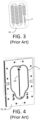
- FIG. 3 shows a perspective view of a process fluid module 10 with detail of an embodiment of an (interior) process fluid path P, such as may be used in the context of the present disclosure.
- FIG. 4 shows a perspective view of an embodiment of a heat exchange enclosure of a general shape which is one shape envisioned for use with the present disclosure.
- raised ridges R are included on interior surfaces 17, 19 of heat exchange enclosures 16, 18.
- the ridges R are positioned to serve as baffles within the region bounded by a seal S (such as an O-ring or other seal).
- the ridges may take various configurations as seen in the embodiments of FIGS. 5 and 6 and in the six variations shown in FIG. 7 .
- the ridges R number at least two, and that the ridges R extend in a direction (a second direction) at least partially crosswise to a first direction from an inflow port or location I to an outflow port or location O.
- the gap G is intentionally larger than needed to provide reliable mechanical separation between the respective major surfaces 12, 14 of the process fluid module 10 and the associated raised ridges R (larger than 0.1 mm, for example). This is because heat exchange performance can be optimized, for a given heat exchange fluid and a given pump power, by making the gap larger than necessary for mechanical separation.
- the gap is greater than 0.1 mm, desirably greater than 0.2 mm or even greater than 0.3 mm or 0.4 mm, while remaining small enough such that the raised ridges still divert a large amount of flow, such as smaller than 1 mm, desirably smaller than 0.9 mm, than 0.8 mm, than 0.7 mm, than 0.6 mm, than 0.5 mm, or even in appropriate cases than 0.4 mm.
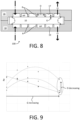
- FIG. 9 is a graph of relative Reynolds numbers (Re, on the y axis) obtained within a heat exchange fluid path with selected heat exchange fluid at a selected maximum pump power as a function of gap G (on the x axis) for three different distances D (decreasing in the direction of the arrow).
- This graph shows that the Reynolds number (and accordingly heat exchange performance) in the heat exchange fluid path HP can be optimized for a given pump power and heat exchange fluid by adjusting (decreasing) the distance D and adjusting (enlarging beyond that required for mechanical clearance) the gap G.
- the distance (D) and the gap (G) can be selected to maximize within to within 80%, 90% or even 95% of maximum possible, an average Reynolds number within the heat exchange fluid path (HP) within a selected heat exchange fluid and a selected heat exchange pump power for pumping the heat exchange fluid.
- the methods and/or devices disclosed herein are generally useful in performing any process that involves mixing, separation, extraction, crystallization, precipitation, or otherwise processing fluids or mixtures of fluids, including multiphase mixtures of fluids-and including fluids or mixtures of fluids including multiphase mixtures of fluids that also contain solids-within a microstructure.
- the processing may include a physical process, a chemical reaction defined as a process that results in the interconversion of organic, inorganic, or both organic and inorganic species, a biochemical process, or any other form of processing.
- the following non-limiting list of reactions may be performed with the disclosed methods and/or devices: oxidation; reduction; substitution; elimination; addition; ligand exchange; metal exchange; and ion exchange.
- reactions of any of the following non-limiting list may be performed with the disclosed methods and/or devices: polymerisation; alkylation; dealkylation; nitration; peroxidation; sulfoxidation; epoxidation; ammoxidation; hydrogenation; dehydrogenation; organometallic reactions; precious metal chemistry/ homogeneous catalyst reactions; carbonylation; thiocarbonylation; alkoxylation; halogenation; dehydrohalogenation; dehalogenation; hydroformylation; carboxylation; decarboxylation; amination; arylation; peptide coupling; aldol condensation; cyclocondensation; dehydrocyclization; esterification; amidation; heterocyclic synthesis; dehydration; alcoholysis; hydrolysis; ammonolysis; etherification; enzymatic synthesis; ketalization; saponification; isomerisation; quaternization; formylation; phase transfer reactions; silylations; nitrile synthesis; phosphoryl
- both flat and curved glass articles may be tempered according to the methods described herein.
- Some elements shown as integrally formed may be constructed of multiple parts or elements, the position of elements may be reversed or otherwise varied, and the nature or number of discrete elements or positions may be altered or varied.
- the order or sequence of any process, logical algorithm, or method steps may be varied or re-sequenced according to alternative embodiments.
- Other substitutions, modifications, changes and omissions may also be made in the design, operating conditions and arrangement of the various exemplary embodiments without departing from the scope of the invention as defined by the appended claims.
Landscapes
- Engineering & Computer Science (AREA)
- Chemical & Material Sciences (AREA)
- Physics & Mathematics (AREA)
- Thermal Sciences (AREA)
- Mechanical Engineering (AREA)
- General Engineering & Computer Science (AREA)
- Organic Chemistry (AREA)
- Chemical Kinetics & Catalysis (AREA)
- Ceramic Engineering (AREA)
- Physical Or Chemical Processes And Apparatus (AREA)
- Heat-Exchange Devices With Radiators And Conduit Assemblies (AREA)
Claims (8)
- Rohrreaktor, umfassendein Rohrreaktormodul (100);wobei das Rohrreaktormodul (100) umfasst:ein Prozessfluidmodul (10) mit einem Prozessfluidkanal (P), der sich dadurch erstreckt, wobei das Prozessfluidmodul (10) einen verlängerten Körper (22) umfasst, der eine Breite (W), eine Länge (L) und eine Dicke (T) aufweist, wobei die Dicke (T) kleiner als die Länge (L) und kleiner als die Breite (W) ist, wobei das Prozessfluidmodul (10) eine erste und eine zweite Hauptfläche (12, 14) auf gegenüberliegenden Seiten des Prozessfluidmoduls (10) aufweist, die senkrecht zu einer Richtung der Dicke (T) des Prozessfluidmoduls (10) ausgerichtet sind; undein erstes Wärmetauschfluidgehäuse (16), das gegen die erste Hauptfläche (12) des Prozessfluidmoduls abgedichtet ist, wobei das erste Wärmetauschfluidgehäuse (16) eine Innenfläche (17) zum Enthalten von Wärmetauschfluid gegen die erste Hauptfläche (12), um einen Wärmetauschfluidpfad (HP) für das Wärmetauschfluid zu bilden, und eine Einströmöffnung oder -stelle (I) zum Zuführen von Wärmetauschfluid zu dem Wärmetauschfluidpfad (HP) und eine Ausströmöffnung oder -stelle (O) zum Aufnehmen von Wärmetauschfluid von dem Wärmetauschfluidpfad (HP) umfasst, wobei die Ausströmöffnung oder -stelle (O) von der Einströmöffnung oder -stelle (I) in einer ersten Richtung beabstandet ist,wobei die Innenfläche (17) des ersten Wärmetauschfluidgehäuses (16) zwei oder mehr erhöhte Rippen (R) umfasst, die sich in einer zweiten Richtung zumindest teilweise quer zu der ersten Richtung erstrecken und einen Abstand (D) zwischen aufeinanderfolgenden der zwei oder mehr erhöhten Rippen aufweisen und einen Spalt (G) zwischen den zwei oder mehr erhöhten Rippen (R) und der ersten Hauptfläche (12) aufweisen; undwobei der Spalt (G) im Bereich von 0,2 bis 0,5 mm liegt und der Abstand (D) im Bereich von 10 mm bis 30 mm liegt.
- Rohrreaktor nach Anspruch 1, ferner umfassend ein zweites Wärmetauschfluidgehäuse (18), das gegen die zweite Hauptfläche (14) des Prozessfluidmoduls (10) abgedichtet ist, wobei das zweite Wärmetauschfluidgehäuse (18) eine Innenfläche (19) zum Enthalten von Wärmetauschfluid gegen die zweite Hauptfläche (14), um den Wärmetauschfluidpfad (HP) für Wärmetauschfluid zu bilden, und eine Einströmöffnung oder -stelle (I) zum Zuführen von Wärmetauschfluid zu dem Wärmetauschfluidpfad (HP) und eine Ausströmöffnung oder -stelle (O) zum Aufnehmen von Wärmetauschfluid von dem Wärmetauschfluidpfad (HP) umfasst,wobei die Innenfläche (19) des zweiten Wärmetauschfluidgehäuses (18) ebenfalls zwei oder mehr erhöhte Rippen (R) umfasst, die sich in einer zweiten Richtung zumindest teilweise quer zu der ersten Richtung erstrecken und den Abstand (D) zwischen aufeinanderfolgenden der zwei oder mehr erhöhten Rippen (R) aufweisen und den Spalt (G) zwischen den zwei oder mehr erhöhten Rippen (R) und der zweiten Hauptfläche (14) aufweisen; undwobei für das zweite Wärmetauschfluidgehäuse der Spalt (G) im Bereich von 0,2 bis 0,5 mm liegt und der Abstand (D) im Bereich von 10 mm bis 30 mm liegt.
- Rohrreaktor nach Anspruch 1 oder Anspruch 2, wobei das Rohrreaktormodul eine Keramik umfasst.
- Rohrreaktor nach Anspruch 3, wobei die Keramik Siliziumkarbid umfasst.
- Rohrreaktor nach Anspruch 3, wobei das Rohrreaktormodul monolithisch ist.
- Rohrreaktor nach Anspruch 3, wobei das erste und das zweite Wärmetauschfluidgehäuse (32, 52) ein Metall umfassen.
- Rohrreaktor nach Anspruch 6, wobei das Metall Aluminium umfasst.
- Rohrreaktor nach einem der Ansprüche 1 bis 7, wobei die Innenfläche (17) drei oder mehr erhöhte Rippen (R) umfasst und die Innenfläche (19) drei oder mehr erhöhte Rippen (R) umfasst.
Applications Claiming Priority (2)
| Application Number | Priority Date | Filing Date | Title |
|---|---|---|---|
| US201962894784P | 2019-08-31 | 2019-08-31 | |
| PCT/US2020/048718 WO2021042023A1 (en) | 2019-08-31 | 2020-08-31 | Improved heat exchange flow reactor |
Publications (3)
| Publication Number | Publication Date |
|---|---|
| EP4022241A1 EP4022241A1 (de) | 2022-07-06 |
| EP4022241B1 true EP4022241B1 (de) | 2025-05-07 |
| EP4022241C0 EP4022241C0 (de) | 2025-05-07 |
Family
ID=72474001
Family Applications (1)
| Application Number | Title | Priority Date | Filing Date |
|---|---|---|---|
| EP20771711.7A Active EP4022241B1 (de) | 2019-08-31 | 2020-08-31 | Verbesserter wärmetauscher-rohrreaktor |
Country Status (6)
| Country | Link |
|---|---|
| US (1) | US11850564B2 (de) |
| EP (1) | EP4022241B1 (de) |
| JP (1) | JP2022546049A (de) |
| KR (1) | KR20220054638A (de) |
| CN (1) | CN114375223B (de) |
| WO (1) | WO2021042023A1 (de) |
Family Cites Families (14)
| Publication number | Priority date | Publication date | Assignee | Title |
|---|---|---|---|---|
| EP0707517B1 (de) * | 1993-07-05 | 1998-09-30 | Packinox | Verfahren und vorrichtung zur regulierung der temperaturen von reaktionen |
| JP2003340273A (ja) | 2002-05-30 | 2003-12-02 | Casio Comput Co Ltd | 化学反応装置及び燃料電池システム並びにその製造方法 |
| JP3979219B2 (ja) * | 2002-08-07 | 2007-09-19 | カシオ計算機株式会社 | 小型化学反応装置 |
| DE102006013503A1 (de) | 2006-03-23 | 2008-01-24 | Esk Ceramics Gmbh & Co. Kg | Plattenwärmetauscher, Verfahren zu dessen Herstellung und dessen Verwendung |
| WO2008026654A1 (fr) * | 2006-08-30 | 2008-03-06 | Kyocera Corporation | dispositif à réaction, système DE pile À combustible, ET appareil électronique |
| JP2008157592A (ja) * | 2006-12-26 | 2008-07-10 | National Institute Of Advanced Industrial & Technology | 積層一体型自己熱交換構造体 |
| DE102008048014A1 (de) | 2008-09-12 | 2010-04-15 | Esk Ceramics Gmbh & Co. Kg | Bauteil aus einem Stapel keramischer Platten |
| EP2535105A1 (de) | 2011-06-14 | 2012-12-19 | Corning Incorporated | Systeme und Verfahren zur Vergrößerung von Mikroreaktoren |
| CN102506606B (zh) | 2011-10-10 | 2014-02-12 | 南通大学 | 一种具有清污功能的管壳式换热器 |
| CN203572278U (zh) | 2013-10-16 | 2014-04-30 | 江苏唯益换热器有限公司 | 一种钎焊板式换热器 |
| FR3032783B1 (fr) * | 2015-02-12 | 2017-03-10 | Air Liquide | Echangeur-reacteur milli-structure pour une production d'hydrogene inferieure a 10 nm3/h |
| WO2016201221A1 (en) * | 2015-06-10 | 2016-12-15 | Corning Incorporated | Thermal cross-talk resistant flow reactor |
| CN107921400B (zh) * | 2015-06-10 | 2020-10-27 | 康宁股份有限公司 | 具有可调传热能力的连续流动反应器 |
| CN205664481U (zh) | 2016-05-13 | 2016-10-26 | 山东建筑大学 | 一种基于混热水箱的地热供暖系统 |
-
2020
- 2020-08-31 EP EP20771711.7A patent/EP4022241B1/de active Active
- 2020-08-31 US US17/636,948 patent/US11850564B2/en active Active
- 2020-08-31 KR KR1020227010202A patent/KR20220054638A/ko active Pending
- 2020-08-31 WO PCT/US2020/048718 patent/WO2021042023A1/en not_active Ceased
- 2020-08-31 JP JP2022513204A patent/JP2022546049A/ja not_active Abandoned
- 2020-08-31 CN CN202080061339.6A patent/CN114375223B/zh active Active
Also Published As
| Publication number | Publication date |
|---|---|
| WO2021042023A1 (en) | 2021-03-04 |
| US11850564B2 (en) | 2023-12-26 |
| KR20220054638A (ko) | 2022-05-03 |
| EP4022241C0 (de) | 2025-05-07 |
| CN114375223A (zh) | 2022-04-19 |
| US20220274082A1 (en) | 2022-09-01 |
| CN114375223B (zh) | 2024-04-02 |
| EP4022241A1 (de) | 2022-07-06 |
| JP2022546049A (ja) | 2022-11-02 |
Similar Documents
| Publication | Publication Date | Title |
|---|---|---|
| EP2437881B1 (de) | Reaktor mit oberer und unterer verteilerstruktur | |
| EP3307430B1 (de) | Gegenüber thermischem übersprechen resistenter strömungsreaktor | |
| JP6145851B2 (ja) | 多流路型マイクロリアクタ・デザイン | |
| EP2435174B1 (de) | Durchflussgeregelte mikrofluidikvorrichtungen | |
| US20120082601A1 (en) | Honeycomb reactor or heat exchanger mixer | |
| CN102293075A (zh) | 用于微型结构的热交换器 | |
| EP4022241B1 (de) | Verbesserter wärmetauscher-rohrreaktor | |
| EP2377607A1 (de) | Flüssigkeitsverbinder für Mikroreaktormodule | |
| US20230381734A1 (en) | Flow reactor with thermal control fluid passage having interchangeable wall structures | |
| US20130206269A1 (en) | Honeycomb-Body-Based Fluidic Interconnectors and Methods | |
| US8303909B2 (en) | Microfluidic assembly | |
| EP3307429B1 (de) | Reaktor mit kontinuierlichem fluss mit abstimmbarer wärmeübertragungsfähigkeit | |
| EP2506961B1 (de) | U-förmig gebogene wabenkörpermischer | |
| CN101605997B (zh) | 高通量的耐压微流体装置 | |
| WO2015087354A2 (en) | A glass lined metal micro-reactor |
Legal Events
| Date | Code | Title | Description |
|---|---|---|---|
| STAA | Information on the status of an ep patent application or granted ep patent |
Free format text: STATUS: UNKNOWN |
|
| STAA | Information on the status of an ep patent application or granted ep patent |
Free format text: STATUS: THE INTERNATIONAL PUBLICATION HAS BEEN MADE |
|
| PUAI | Public reference made under article 153(3) epc to a published international application that has entered the european phase |
Free format text: ORIGINAL CODE: 0009012 |
|
| STAA | Information on the status of an ep patent application or granted ep patent |
Free format text: STATUS: REQUEST FOR EXAMINATION WAS MADE |
|
| 17P | Request for examination filed |
Effective date: 20220317 |
|
| AK | Designated contracting states |
Kind code of ref document: A1 Designated state(s): AL AT BE BG CH CY CZ DE DK EE ES FI FR GB GR HR HU IE IS IT LI LT LU LV MC MK MT NL NO PL PT RO RS SE SI SK SM TR |
|
| DAV | Request for validation of the european patent (deleted) | ||
| DAX | Request for extension of the european patent (deleted) | ||
| STAA | Information on the status of an ep patent application or granted ep patent |
Free format text: STATUS: EXAMINATION IS IN PROGRESS |
|
| 17Q | First examination report despatched |
Effective date: 20231129 |
|
| GRAP | Despatch of communication of intention to grant a patent |
Free format text: ORIGINAL CODE: EPIDOSNIGR1 |
|
| STAA | Information on the status of an ep patent application or granted ep patent |
Free format text: STATUS: GRANT OF PATENT IS INTENDED |
|
| INTG | Intention to grant announced |
Effective date: 20241128 |
|
| GRAS | Grant fee paid |
Free format text: ORIGINAL CODE: EPIDOSNIGR3 |
|
| GRAA | (expected) grant |
Free format text: ORIGINAL CODE: 0009210 |
|
| STAA | Information on the status of an ep patent application or granted ep patent |
Free format text: STATUS: THE PATENT HAS BEEN GRANTED |
|
| AK | Designated contracting states |
Kind code of ref document: B1 Designated state(s): AL AT BE BG CH CY CZ DE DK EE ES FI FR GB GR HR HU IE IS IT LI LT LU LV MC MK MT NL NO PL PT RO RS SE SI SK SM TR |
|
| REG | Reference to a national code |
Ref country code: GB Ref legal event code: FG4D |
|
| REG | Reference to a national code |
Ref country code: CH Ref legal event code: EP |
|
| REG | Reference to a national code |
Ref country code: DE Ref legal event code: R096 Ref document number: 602020050891 Country of ref document: DE |
|
| REG | Reference to a national code |
Ref country code: IE Ref legal event code: FG4D |
|
| U01 | Request for unitary effect filed |
Effective date: 20250604 |
|
| U07 | Unitary effect registered |
Designated state(s): AT BE BG DE DK EE FI FR IT LT LU LV MT NL PT RO SE SI Effective date: 20250611 |
|
| U20 | Renewal fee for the european patent with unitary effect paid |
Year of fee payment: 6 Effective date: 20250710 |
|
| PG25 | Lapsed in a contracting state [announced via postgrant information from national office to epo] |
Ref country code: ES Free format text: LAPSE BECAUSE OF FAILURE TO SUBMIT A TRANSLATION OF THE DESCRIPTION OR TO PAY THE FEE WITHIN THE PRESCRIBED TIME-LIMIT Effective date: 20250507 |
|
| PG25 | Lapsed in a contracting state [announced via postgrant information from national office to epo] |
Ref country code: GR Free format text: LAPSE BECAUSE OF FAILURE TO SUBMIT A TRANSLATION OF THE DESCRIPTION OR TO PAY THE FEE WITHIN THE PRESCRIBED TIME-LIMIT Effective date: 20250808 Ref country code: NO Free format text: LAPSE BECAUSE OF FAILURE TO SUBMIT A TRANSLATION OF THE DESCRIPTION OR TO PAY THE FEE WITHIN THE PRESCRIBED TIME-LIMIT Effective date: 20250807 |
|
| PG25 | Lapsed in a contracting state [announced via postgrant information from national office to epo] |
Ref country code: PL Free format text: LAPSE BECAUSE OF FAILURE TO SUBMIT A TRANSLATION OF THE DESCRIPTION OR TO PAY THE FEE WITHIN THE PRESCRIBED TIME-LIMIT Effective date: 20250507 |
|
| PGFP | Annual fee paid to national office [announced via postgrant information from national office to epo] |
Ref country code: GB Payment date: 20250710 Year of fee payment: 6 |
|
| PG25 | Lapsed in a contracting state [announced via postgrant information from national office to epo] |
Ref country code: HR Free format text: LAPSE BECAUSE OF FAILURE TO SUBMIT A TRANSLATION OF THE DESCRIPTION OR TO PAY THE FEE WITHIN THE PRESCRIBED TIME-LIMIT Effective date: 20250507 |
|
| PGFP | Annual fee paid to national office [announced via postgrant information from national office to epo] |
Ref country code: CH Payment date: 20250901 Year of fee payment: 6 |
|
| PG25 | Lapsed in a contracting state [announced via postgrant information from national office to epo] |
Ref country code: RS Free format text: LAPSE BECAUSE OF FAILURE TO SUBMIT A TRANSLATION OF THE DESCRIPTION OR TO PAY THE FEE WITHIN THE PRESCRIBED TIME-LIMIT Effective date: 20250807 |
|
| PG25 | Lapsed in a contracting state [announced via postgrant information from national office to epo] |
Ref country code: IS Free format text: LAPSE BECAUSE OF FAILURE TO SUBMIT A TRANSLATION OF THE DESCRIPTION OR TO PAY THE FEE WITHIN THE PRESCRIBED TIME-LIMIT Effective date: 20250907 |
|
| PG25 | Lapsed in a contracting state [announced via postgrant information from national office to epo] |
Ref country code: SM Free format text: LAPSE BECAUSE OF FAILURE TO SUBMIT A TRANSLATION OF THE DESCRIPTION OR TO PAY THE FEE WITHIN THE PRESCRIBED TIME-LIMIT Effective date: 20250507 |
|
| PG25 | Lapsed in a contracting state [announced via postgrant information from national office to epo] |
Ref country code: CZ Free format text: LAPSE BECAUSE OF FAILURE TO SUBMIT A TRANSLATION OF THE DESCRIPTION OR TO PAY THE FEE WITHIN THE PRESCRIBED TIME-LIMIT Effective date: 20250507 |
|
| PG25 | Lapsed in a contracting state [announced via postgrant information from national office to epo] |
Ref country code: SK Free format text: LAPSE BECAUSE OF FAILURE TO SUBMIT A TRANSLATION OF THE DESCRIPTION OR TO PAY THE FEE WITHIN THE PRESCRIBED TIME-LIMIT Effective date: 20250507 |
|
| PLBE | No opposition filed within time limit |
Free format text: ORIGINAL CODE: 0009261 |
|
| STAA | Information on the status of an ep patent application or granted ep patent |
Free format text: STATUS: NO OPPOSITION FILED WITHIN TIME LIMIT |
|
| REG | Reference to a national code |
Ref country code: CH Ref legal event code: L10 Free format text: ST27 STATUS EVENT CODE: U-0-0-L10-L00 (AS PROVIDED BY THE NATIONAL OFFICE) Effective date: 20260318 |