EP4021780B1 - Kinderwagengestell und kinderwagen - Google Patents
Kinderwagengestell und kinderwagen Download PDFInfo
- Publication number
- EP4021780B1 EP4021780B1 EP20800806.0A EP20800806A EP4021780B1 EP 4021780 B1 EP4021780 B1 EP 4021780B1 EP 20800806 A EP20800806 A EP 20800806A EP 4021780 B1 EP4021780 B1 EP 4021780B1
- Authority
- EP
- European Patent Office
- Prior art keywords
- support member
- operating
- lower support
- disposed
- engaging
- Prior art date
- Legal status (The legal status is an assumption and is not a legal conclusion. Google has not performed a legal analysis and makes no representation as to the accuracy of the status listed.)
- Active
Links
Images


Classifications
-
- B—PERFORMING OPERATIONS; TRANSPORTING
- B62—LAND VEHICLES FOR TRAVELLING OTHERWISE THAN ON RAILS
- B62B—HAND-PROPELLED VEHICLES, e.g. HAND CARTS OR PERAMBULATORS; SLEDGES
- B62B7/00—Carriages for children; Perambulators, e.g. dolls' perambulators
- B62B7/04—Carriages for children; Perambulators, e.g. dolls' perambulators having more than one wheel axis; Steering devices therefor
- B62B7/06—Carriages for children; Perambulators, e.g. dolls' perambulators having more than one wheel axis; Steering devices therefor collapsible or foldable
- B62B7/08—Carriages for children; Perambulators, e.g. dolls' perambulators having more than one wheel axis; Steering devices therefor collapsible or foldable in the direction of, or at right angles to, the wheel axis
- B62B7/083—Carriages for children; Perambulators, e.g. dolls' perambulators having more than one wheel axis; Steering devices therefor collapsible or foldable in the direction of, or at right angles to, the wheel axis the wheel axes being moved from each other during folding
-
- B—PERFORMING OPERATIONS; TRANSPORTING
- B62—LAND VEHICLES FOR TRAVELLING OTHERWISE THAN ON RAILS
- B62B—HAND-PROPELLED VEHICLES, e.g. HAND CARTS OR PERAMBULATORS; SLEDGES
- B62B7/00—Carriages for children; Perambulators, e.g. dolls' perambulators
- B62B7/04—Carriages for children; Perambulators, e.g. dolls' perambulators having more than one wheel axis; Steering devices therefor
- B62B7/06—Carriages for children; Perambulators, e.g. dolls' perambulators having more than one wheel axis; Steering devices therefor collapsible or foldable
- B62B7/062—Coupling unit between front wheels, rear wheels and handle
-
- B—PERFORMING OPERATIONS; TRANSPORTING
- B62—LAND VEHICLES FOR TRAVELLING OTHERWISE THAN ON RAILS
- B62B—HAND-PROPELLED VEHICLES, e.g. HAND CARTS OR PERAMBULATORS; SLEDGES
- B62B7/00—Carriages for children; Perambulators, e.g. dolls' perambulators
- B62B7/04—Carriages for children; Perambulators, e.g. dolls' perambulators having more than one wheel axis; Steering devices therefor
- B62B7/06—Carriages for children; Perambulators, e.g. dolls' perambulators having more than one wheel axis; Steering devices therefor collapsible or foldable
- B62B7/064—Carriages for children; Perambulators, e.g. dolls' perambulators having more than one wheel axis; Steering devices therefor collapsible or foldable the handle bar being parallel to the front leg
- B62B7/066—Carriages for children; Perambulators, e.g. dolls' perambulators having more than one wheel axis; Steering devices therefor collapsible or foldable the handle bar being parallel to the front leg the handle bar moves in parallel relation during folding
-
- B—PERFORMING OPERATIONS; TRANSPORTING
- B62—LAND VEHICLES FOR TRAVELLING OTHERWISE THAN ON RAILS
- B62B—HAND-PROPELLED VEHICLES, e.g. HAND CARTS OR PERAMBULATORS; SLEDGES
- B62B7/00—Carriages for children; Perambulators, e.g. dolls' perambulators
- B62B7/04—Carriages for children; Perambulators, e.g. dolls' perambulators having more than one wheel axis; Steering devices therefor
- B62B7/06—Carriages for children; Perambulators, e.g. dolls' perambulators having more than one wheel axis; Steering devices therefor collapsible or foldable
- B62B7/10—Carriages for children; Perambulators, e.g. dolls' perambulators having more than one wheel axis; Steering devices therefor collapsible or foldable by folding down the body to the wheel carriage or by retracting projecting parts into the box-shaped body
-
- B—PERFORMING OPERATIONS; TRANSPORTING
- B62—LAND VEHICLES FOR TRAVELLING OTHERWISE THAN ON RAILS
- B62B—HAND-PROPELLED VEHICLES, e.g. HAND CARTS OR PERAMBULATORS; SLEDGES
- B62B9/00—Accessories or details specially adapted for children's carriages or perambulators
- B62B9/08—Braking mechanisms; Locking devices against movement
- B62B9/082—Braking mechanisms; Locking devices against movement foot operated
-
- B—PERFORMING OPERATIONS; TRANSPORTING
- B62—LAND VEHICLES FOR TRAVELLING OTHERWISE THAN ON RAILS
- B62B—HAND-PROPELLED VEHICLES, e.g. HAND CARTS OR PERAMBULATORS; SLEDGES
- B62B9/00—Accessories or details specially adapted for children's carriages or perambulators
- B62B9/08—Braking mechanisms; Locking devices against movement
- B62B9/087—Braking mechanisms; Locking devices against movement by locking in a braking position
-
- B—PERFORMING OPERATIONS; TRANSPORTING
- B62—LAND VEHICLES FOR TRAVELLING OTHERWISE THAN ON RAILS
- B62B—HAND-PROPELLED VEHICLES, e.g. HAND CARTS OR PERAMBULATORS; SLEDGES
- B62B2205/00—Hand-propelled vehicles or sledges being foldable or dismountable when not in use
- B62B2205/12—Collapsible wheels
-
- B—PERFORMING OPERATIONS; TRANSPORTING
- B62—LAND VEHICLES FOR TRAVELLING OTHERWISE THAN ON RAILS
- B62B—HAND-PROPELLED VEHICLES, e.g. HAND CARTS OR PERAMBULATORS; SLEDGES
- B62B2205/00—Hand-propelled vehicles or sledges being foldable or dismountable when not in use
- B62B2205/18—Geared articulations
-
- B—PERFORMING OPERATIONS; TRANSPORTING
- B62—LAND VEHICLES FOR TRAVELLING OTHERWISE THAN ON RAILS
- B62B—HAND-PROPELLED VEHICLES, e.g. HAND CARTS OR PERAMBULATORS; SLEDGES
- B62B2205/00—Hand-propelled vehicles or sledges being foldable or dismountable when not in use
- B62B2205/20—Catches; Locking or releasing an articulation
- B62B2205/24—Catches; Locking or releasing an articulation to hold in the folded position
-
- B—PERFORMING OPERATIONS; TRANSPORTING
- B62—LAND VEHICLES FOR TRAVELLING OTHERWISE THAN ON RAILS
- B62B—HAND-PROPELLED VEHICLES, e.g. HAND CARTS OR PERAMBULATORS; SLEDGES
- B62B2301/00—Wheel arrangements; Steering; Stability; Wheel suspension
- B62B2301/20—Resilient wheel suspension using springs
Definitions
- the invention is defined by the claims.
- the present invention aims at providing a stroller frame with high safety, small folding size and capable of effectively avoiding accident caused by accidental folding.
- the present invention aims at providing a stroller with the aforesaid stroller frame.
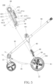
- the claimed stroller frame includes a front leg, a bottom tube, a rear leg, an upper support member and a lower support member.
- the front leg, the bottom tube, the lower support member and the upper support member are pivotally connected to each other to form a four-bar linkage structure.
- the rear leg is connected to an end of the bottom tube close to the lower support member.
- a lock mechanism is disposed at a pivot joint between the upper support member and the lower support member.
- the lock mechanism is able to lock the upper support member and the lower support member at an expanded angle, such that the front leg is able to be expanded with respect to the bottom tube.
- the lock mechanism is unlocked to release the upper support member and the lower support member, such that the front leg is able to be folded with respect to the bottom tube.
- the front leg, the bottom tube, the lower support member and the upper support member of the invention are pivotally connected to each other to form a four-bar linkage structure, and the lock mechanism is disposed at the pivot joint between the upper support member and the lower support member, such that the stroller frame can be flexibly folded through the four-bar linkage structure and the lock mechanism can be operated to lock or unlock the upper support member and the lower support member, so as to lock the expanded stroller frame. Accordingly, the invention can avoid accident caused by accidental folding of the stroller frame, and the folded stroller frame has a small size and is easy to carry.
- the fixing member is an engaging recess disposed on the upper support member and the engaging member includes an engaging block matching with
- the lock mechanism further includes a first elastic member.
- the first elastic member is connected to the engaging member and provides an elastic force for the engaging member to engage with the fixing member.
- the lock mechanism further comprises a decorative cover and a first reinforcing member.
- the lower support member has a first sliding groove for the engaging member to slide therein.
- the decorative cover is disposed on the first sliding groove and covers the first sliding groove.
- the decorative cover encloses the engaging member in the first sliding groove.
- the first reinforcing member is disposed on the engaging member.
- the operating member comprises a first operating portion, a first transmitting portion connected to the first operating portion, and a sliding block.
- the first transmitting portion is disposed on the lower support member along a direction perpendicular to a moving direction of the engaging member and has a first inclined groove inclining with respect to the moving direction of the engaging member.
- the sliding block is slidably connected to the first inclined groove and disposed on the engaging member. The first operating portion is operated to drive the first transmitting portion to slide with respect to the lower support member, such that the sliding block slides along the first inclined groove to disengage the engaging member from the fixing member.
- the lock mechanism further comprises a second safety lock and the second safety lock selectively restrains an operation of the operating member.
- the second safety lock includes a second operating portion.
- the second operating portion is movably connected to the operating member or the lower support member.
- the second operating portion is operated to move to an unlock position and a lock position with respect to the operating member.
- the second operating portion engages with the operating member or the lower support member at the unlock position to restrain the operation of the operating member.
- the second operating portion disengages from the operating member or the lower support member at the lock position to unlock the operating member.
- the second safety lock further includes a second elastic member and the second elastic member provides an elastic force for the second operating portion to lock the operating member.
- a restraining member is disposed between the second operating portion and the operating member or the lower support member.
- the restraining member enables the second operating portion to move between the unlock position and the lock position with respect to the operating member.
- the rear leg includes a transverse tube.
- the transverse tube is connected to the bottom tube.
- the lower support member is pivotally connected to the transverse tube, such that that the lower support member is pivotally connected to the bottom tube through the transverse tube.
- the second operating portion is slidably connected to the lower support member.
- the lock mechanism 60 further includes a first reinforcing member 66.
- the decorative cover 65 is disposed on the first sliding groove 51 and covers the first sliding groove 51 to enclose the engaging member 62 in the first sliding groove 51, so as to prevent the engaging member 62 from being exposed to the external environment and prevent dust other impurities from entering the first sliding groove 51 and affecting the sliding of the engaging member 62 in the first sliding groove 51.
- the decorative cover 65 plays a decorative role and enhances the beauty of the lock mechanism 60.
- the first reinforcing member 66 is disposed on the engaging member 62 to increase the rigidity of the engaging member 62, so as to avoid damage to the engaging member 62 during sliding and engaging with the engaging recess and extend the life of the engaging member 62.
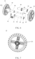
- the brake mechanism 80 further includes a sleeve 84, a first connecting member 85 for connecting the rear wheel 22, a second connecting member 86, and a fourth elastic member 87.
- the sleeve 84 is sleeved on the transverse tube 21 and able to rotate around an axle center of the transverse tube 21.
- the first connecting member 85 is disposed on the transverse tube 21 and static with respect to the sleeve 84.
- the first connecting member 85 has a through hole 851 for the brake pin 82 to pass through along the axial direction of the transverse tube 21.
- the brake pin 82 is disposed in the through hole 851 and able to move along the axial direction of the transverse tube 21.
- the second connecting member 86 is disposed on the transverse tube 21 and located between the lower support member 50 and the first connecting member 85.
- the first connecting member 85 and the second connecting member 86 jointly cover the transverse tube 21 and the driving member 83 is sealed and assembled between the first connecting member 85 and the second connecting member 86.
- the fourth elastic member 87 is specifically a spring.
- the fourth elastic member 87 provides an elastic force for ejecting the brake pin 82 out of the brake hole 221.
- the stroller frame 100 of this embodiment further includes a fifth elastic member 102.
- the fifth elastic member 102 is specifically a spring.
- the lower support member 50 has a fourth sliding groove 53 (as shown in FIG. 4 ).
- the transverse tube 21 passes through the fourth sliding groove 53 and is pivotally connected to a lower end of the lower support member 50.
- the fifth elastic member 102 is disposed in the fourth sliding groove 53 and abuts against the lower support member 50 and the transverse tube 21.
- the fifth elastic member 102 buffers vibration of the lower support member 50 and the transverse tube 21, so as to avoid direct transmission of the vibration generated by the stroller during travel to infants and children, thereby effectively improving the comfort of the stroller during travel.
- the second safety lock 67 further includes a lower operating member 674, a third elastic member 675 and a second transmitting portion.
- the lower operating member 674 is movably connected to the transverse tube 21.
- the second transmitting portion is connected between the lower operating member 674 and the second operating portion 671.
- the lower operating member 674 is rotatably connected to the transverse tube 21 and the second transmitting portion is a wire.
- the wire is specifically a steel wire.
- the wire connects the second operating portion 671 and the lower operating member 674, such that the second operating portion 671 and the lower operating member 674 can be linked by the wire.
- the lower operating member 674 is operated to drive the second operating portion 671 to unlock the operating member 61 through the second transmitting portion.
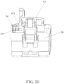
- the difference between this embodiment and the first embodiment is the arrangement of the second operating portion 671.
- the second operating portion 671 of this embodiment is slidably connected to the lower support member 50.
- the second operating portion 671 is disposed at a right side (or left side) of the operating member 61.
- the second operating portion 671 is disposed at an upper side (or lower side) of the operating member 61, as shown in FIG. 21 .
- the second operating portion 671 may also be disposed at an inclined side of the operating member 61.
- the different orientations of the second operating portion 671 disposed on the operating member 61 are determined according to practical applications, so the invention is not limited to a specific manner.
Landscapes
- Engineering & Computer Science (AREA)
- Chemical & Material Sciences (AREA)
- Combustion & Propulsion (AREA)
- Transportation (AREA)
- Mechanical Engineering (AREA)
- Health & Medical Sciences (AREA)
- Public Health (AREA)
- Carriages For Children, Sleds, And Other Hand-Operated Vehicles (AREA)
Claims (15)
- Kinderwagenrahmen (100), umfassend eine vordere Strebe (10), ein unteres Rohr (30), eine hintere Strebe (20), ein oberes Stützelement (40) und ein unteres Stützelement (50), wobei die vordere Strebe (10), das untere Rohr (30), das untere Stützelement (50) und das obere Stützelement (40) schwenkbar miteinander verbunden sind, um eine Vierstangen-Verbindungsstruktur zu bilden, wobei die hintere Strebe (20) mit einem Ende des unteren Rohrs (30) in der Nähe des unteren Stützelements (50) verbunden ist, einen Verriegelungsmechanismus (60), der an einer Drehverbindung zwischen dem oberen Stützelement (40) und dem unteren Stützelement (50) angeordnet ist, wobei der Verriegelungsmechanismus (60), das obere Stützelement (40) und das untere Stützelement (50) in einem aufgeweiteten Winkel verriegeln kann, so dass die vordere Strebe (10) in Bezug auf das untere Rohr (30) expandiert werden kann, wobei der Verriegelungsmechanismus (60) entriegelt wird, um das obere Stützelement (40) und das untere Stützelement (50) freizugeben, so dass die vordere Strebe (10) in Bezug auf das untere Rohr (30) geklappt werden kann, dadurch gekennzeichnet, dass der Verriegelungsmechanismus (60) ein Betätigungselement (61), ein Eingriffselement (62) und ein mit dem Eingriffselement (62) in Eingriff stehendes fixierendes Element (63) umfasst, wobei das Eingriffselement (62) beweglich am unteren Stützelement (50) angeordnet ist, das fixierende Element (63) am oberen Stützelement (40) angeordnet ist, das fixierende Element (63) mit dem Eingriffselement (62) korrespondiert und in dieses eingreift, wenn sich das obere Stützelement (40) und das untere Stützelement (50) in dem aufgeweiteten Winkel befinden, das Betätigungselement (61) mit dem Eingriffselement (62) verbunden ist und das Eingriffselement (62) steuert, um von dem fixierenden Element (63) gelöst zu werden, um den Verriegelungsmechanismus (60) zu entriegeln.
- Kinderwagenrahmen (100) nach Anspruch 1, dadurch gekennzeichnet, dass das fixierende Element (63) eine Eingriffsaussparung ist, die an dem oberen Stützelement (40) angeordnet ist, und dass das Eingriffselement (62) einen Eingriffsblock (621) umfasst, der zu der Eingriffsaussparung passt;
und/oder ferner dadurch gekennzeichnet, dass der Verriegelungsmechanismus (60) ferner ein erstes elastisches Element (64) umfasst, wobei das erste elastische Element (64) mit dem Eingriffselement (62) verbunden ist und eine elastische Kraft für das Eingriffselement (62) bereitstellt, um mit dem fixierenden Element (63) in Eingriff zu kommen. - Kinderwagenrahmen (100) nach Anspruch 1, dadurch gekennzeichnet, dass das Eingriffselement (62) verschiebbar mit dem unteren Stützelement (50) verbunden ist und in der Lage ist, in Bezug auf das untere Stützelement (50) zu gleiten, um mit dem fixierenden Element (63) in Eingriff zu kommen oder sich von diesem zu lösen;
insbesondere dadurch gekennzeichnet, dass der Verriegelungsmechanismus (60) ferner eine dekorative Abdeckung (65) und ein erstes Verstärkungselement (66) umfasst, wobei das untere Stützelement (50) eine erste Gleitnut (51) aufweist, in der das Eingriffselement (62) gleiten kann, die dekorative Abdeckung (65) auf der ersten Gleitnut (51) angeordnet ist und die erste Gleitnut (51) abdeckt, die dekorative Abdeckung (65) das Eingriffselement (62) in der ersten Gleitnut (51) umschließt und das erste Verstärkungselement (66) auf dem Eingriffselement (62) angeordnet ist. - Kinderwagenrahmen (100) nach Anspruch 1, ferner dadurch gekennzeichnet, dass das Betätigungselement (61) einen ersten Betätigungsteil (611), einen ersten Übertragungsteil (612), der mit dem ersten Betätigungsteil (611) verbunden ist, und einen Gleitblock (613) umfasst, wobei der erste Übertragungsteil (612) an dem unteren Stützelement (50) entlang einer Richtung senkrecht zu einer Bewegungsrichtung des Eingriffselements (62) angeordnet ist und eine erste schräge Nut (6121) aufweist, die in Bezug auf die Bewegungsrichtung des Eingriffselements (62) geneigt ist, der Gleitblock (613) gleitend mit der ersten schrägen Nut (6121) verbunden und auf dem Eingriffselement (62) angeordnet ist, der erste Betätigungsteil (611) betätigt wird, um den ersten Übertragungsteil (612) anzutreiben, um in Bezug auf das untere Stützelement (50) zu gleiten, so dass der Gleitblock (613) entlang der ersten schrägen Nut (6121) gleitet, um das Eingriffselement (62) von dem fixierenden Element (63) zu lösen.
- Kinderwagenrahmen (100) nach Anspruch 1, ferner dadurch gekennzeichnet, dass der Verriegelungsmechanismus (60) ferner eine zweite Sicherheitssperre (67) umfasst und die zweite Sicherheitssperre (67) selektiv eine Betätigung des Betätigungselements (61) verhindert.
- Kinderwagenrahmen (100) nach Anspruch 5, ferner dadurch gekennzeichnet, dass die zweite Sicherheitssperre (67) einen zweiten Betätigungsteil (671) umfasst, der zweite Betätigungsteil (671) beweglich mit dem Betätigungselement (61) oder dem unteren Stützelement (50) verbunden ist, der zweite Betätigungsteil (671) betätigt wird, um sich in eine Entriegelungsposition und eine Verriegelungsposition in Bezug auf das Betätigungselement (61) zu bewegen, der zweite Betätigungsteil (671) in der Entriegelungsposition in das Betätigungselement (61) oder das untere Stützelement (50) eingreift, um die Betätigung des Betätigungselements (61) einzuschränken, und der zweite Betätigungsteil (671) in der Verriegelungsposition von dem Betätigungselement (61) oder dem unteren Stützelement (50) gelöst wird, um das Betätigungselement (61) zu entriegeln.
- Kinderwagenrahmen (100) nach Anspruch 6, ferner dadurch gekennzeichnet, dass die zweite Sicherheitssperre (67) ferner ein zweites elastisches Element (672) umfasst und das zweite elastische Element (672) eine elastische Kraft für den zweiten Betätigungsteil (671) bereitstellt, um das Betätigungselement (61) zu verriegeln;und/oder ferner dadurch gekennzeichnet, dass ein Rückhalteelement (673) zwischen dem zweiten Betätigungsteil (671) und dem Betätigungselement (61) oder dem unteren Stützelement (50) angeordnet ist, wobei das Rückhalteelement (673) dem zweiten Betätigungsteil (671) ermöglicht, sich zwischen der Entriegelungsposition und der Verriegelungsposition in Bezug auf das Betätigungselement (61) zu bewegen;und/oder ferner dadurch gekennzeichnet, dass die hintere Strebe (20) ein Querrohr (21) umfasst, das Querrohr (21) mit dem unteren Rohr (30) verbunden ist und das untere Stützelement (50) schwenkbar mit dem Querrohr (21) verbunden ist, so dass das untere Stützelement (50) durch das Querrohr (21) schwenkbar mit dem unteren Rohr (30) verbunden ist; insbesondere weiter dadurch gekennzeichnet, dass der zweite Betätigungsteil (671) beweglich mit dem unteren Stützelement (50) verbunden ist, die zweite Sicherheitssperre (67) ferner ein unteres Betätigungselement (674), ein drittes elastisches Element (675) und einen zweiten Übertragungsteil umfasst, wobei das untere Betätigungselement (674) beweglich mit dem Querrohr (21) verbunden ist, der zweite Übertragungsteil zwischen dem unteren Betätigungselement (674) und dem zweiten Betätigungsteil (671) verbunden ist, das untere Betätigungselement (674) betätigt wird, um den zweiten Betätigungsteil (671) anzutreiben, um das Betätigungselement (61) durch den zweiten Übertragungsteil zu entriegeln, und das dritte elastische Element (675) eine elastische Kraft für das untere Betätigungselement (674) bereitstellt, um das Betätigungselement (61) zu verriegeln; insbesondere weiter dadurch gekennzeichnet, dass das untere Betätigungselement (674) drehbar mit dem Querrohr (21) verbunden ist und der zweite Übertragungsteil ein Draht ist.
- Kinderwagenrahmen (100) nach Anspruch 6, dadurch gekennzeichnet, dass der zweite Betätigungsteil (671) verschiebbar mit dem unteren Stützelement (50) verbunden ist;
insbesondere weiter dadurch gekennzeichnet, dass der zweite Betätigungsteil (671) an einer Oberseite, einer Unterseite, einer linken Seite oder einer rechten Seite des Betätigungselements (61) angeordnet ist. - Kinderwagenrahmen (100) nach Anspruch 1, dadurch gekennzeichnet, dass der Kinderwagenrahmen (100) ferner einen Verbindungsmechanismus (70) umfasst, die vordere Strebe (10) eine Vorderstrebenstange (11) und ein Vorderradelement (12) umfasst, das Vorderradelement (12) drehbar mit der Vorderstrebenstange (11) verbunden ist, um einen ersten Schwenkpunkt zu bilden, die Vorderstrebenstange (11) schwenkbar mit dem unteren Rohr (30) verbunden ist, um einen zweiten Schwenkpunkt zu bilden, der Verbindungsmechanismus (70) zwischen dem ersten Schwenkpunkt und dem zweiten Schwenkpunkt angeordnet ist, so dass der Verbindungsmechanismus (70) das Vorderradelement (12) antreibt, um in Bezug auf die Vorderstrebenstange (11) geklappt zu werden, wenn die Vorderstrebenstange (11) in Bezug auf das unterer Rohr (30) geklappt wird.
- Kinderwagenrahmen (100) nach Anspruch 9, dadurch gekennzeichnet, dass der Verbindungsmechanismus (70) eine erste Zahnradplatte (71), die an der Vorderstrebenstange (11) angeordnet ist, eine zweite Zahnradplatte (72), die an dem Vorderradelement (12) angeordnet ist, und ein Synchronisationszahnrad (73), das an dem unteren Rohr (30) angeordnet ist, umfasst, wobei das Synchronisationszahnrad (73) mit den Zähnen der ersten Zahnradplatte (71) und den Zähnen der zweiten Zahnradplatte (72) synchron kämmt;
und/oder weiter dadurch gekennzeichnet, dass der Verbindungsmechanismus (70) eine erste Zahnradplatte (71), die auf dem unteren Rohr (30) angeordnet ist, eine zweite Zahnradplatte (72), die auf dem vorderen Radelement (12) angeordnet ist, und ein Synchronisationszahnrad (73), das auf der Vorderstrebenstange (11) angeordnet ist, umfasst, wobei das Synchronisationszahnrad (73) mit den Zähnen der ersten Zahnradplatte (71) und den Zähnen der zweiten Zahnradplatte (72) synchron kämmt. - Kinderwagenrahmen (100) nach Anspruch 1, dadurch gekennzeichnet, dass der Kinderwagenrahmen (100) ferner einen Bremsmechanismus (80) umfasst, die hintere Strebe (20) ein Querrohr (21) und ein Hinterrad (22) umfasst, gegenüberliegende Enden des Querrohrs (21) mit dem Hinterrad (22) ausgestattet sind, der Bremsmechanismus (80) am Querrohr (21) angeordnet ist und der Bremsmechanismus (80) zum Abbremsen des Hinterrads (22) betätigt wird.
- Kinderwagenrahmen (100) nach Anspruch 11, ferner dadurch gekennzeichnet, dass der Bremsmechanismus (80) ein Bremspedal (81) und einen Bremsstift (82) umfasst, ein Umfang des Hinterrads (22) eine Vielzahl von Bremslöchern (221) zur Aufnahme des Bremsstifts (82) aufweist, das Bremspedal (81) beweglich auf dem Querrohr (21) angeordnet und in der Lage ist, den Bremsstift (82) so anzutreiben, dass er in eines der Bremslöcher (221) eingeführt wird, um das Hinterrad (22) zu bremsen.
- Kinderwagenrahmen (100) nach Anspruch 12, ferner dadurch gekennzeichnet, dass der Bremsmechanismus (80) ferner ein viertes elastisches Element (87) umfasst und das vierte elastische Element (87) eine elastische Kraft zum Ausstoßen des Bremsstifts (82) aus dem Bremsloch (221) bereitstellt;
und/oder ferner dadurch gekennzeichnet, dass der Bremsmechanismus (80) ferner ein Antriebselement (83) umfasst, das auf das Querrohr (21) aufgeschoben ist und sich um eine Achsenmitte des Querrohrs (21) drehen kann, wobei das Bremspedal (81) beweglich auf dem Querrohr (21) angeordnet ist und das Antriebselement (83) zur Drehung antreibt, eine Seite des Antriebselements (83) eine geneigte Wand (8312) gegenüber dem Bremsstift (82) aufweist, die geneigte Wand (8312) entlang einer Drehrichtung des Antriebselements (83) geneigt ist, und der Bremsstift (82) verschiebbar mit dem Querrohr (21) verbunden ist und an der geneigten Wand (8312) anliegt. - Kinderwagenrahmen (100) nach Anspruch 1, ferner dadurch gekennzeichnet, dass der Kinderwagenrahmen (100) ferner einen Griff (90) umfasst, wobei der Griff (90) teleskopisch mit einem Ende der vorderen Strebe (10) verbunden ist, das mit dem oberen Stützelement (40) verbunden ist, die hintere Strebe (20) einen Klapphaken (852) zum Eingreifen in den Griff (90) aufweist, so dass der Griff (90) in den Klapphaken (852) eingreift, wenn der Griff (90) in die vordere Strebe (10) eingezogen und die vordere Strebe (10) in Bezug auf das untere Rohr (30) geklappt ist;und/oder ferner dadurch gekennzeichnet, dass der Kinderwagenrahmen (100) ferner eine Sitzbefestigungsbasis (101) zum Installieren eines Sitzes umfasst, wobei die Sitzbefestigungsbasis (101) mit der vorderen Strebe (10) verbunden ist, das obere Stützelement (40) schwenkbar mit der Sitzbefestigungsbasis (101) verbunden ist, und das obere Stützelement (40) durch die Sitzbefestigungsbasis (101) schwenkbar mit der vorderen Strebe (10) verbunden ist;und/oder ferner dadurch gekennzeichnet, dass der Kinderwagenrahmen (100) ferner ein fünftes elastisches Element (102) umfasst, die hintere Strebe (20) ein Querrohr (21) umfasst, das Querrohr (21) mit dem unteren Rohr (30) verbunden ist, das untere Stützelement (50) schwenkbar mit dem Querrohr (21) verbunden ist, so dass das untere Stützelement (50) durch das Querrohr (21) schwenkbar mit dem unteren Rohr (30) verbunden ist, eine vierte Gleitnut (53) zwischen dem unteren Stützelement (50) und dem Querrohr (21) ausgebildet ist, das fünfte elastische Element (102) in der vierten Gleitnut (53) angeordnet ist und an dem unteren Stützelement (50) und dem Querrohr (21) anliegt, und das fünfte elastische Element (102) Schwingungen des unteren Stützelements (50) und des Querrohrs (21) puffert.
- Kinderwagen, dadurch gekennzeichnet, dass der Kinderwagen einen Sitz und den Kinderwagenrahmen (100) nach einem der Ansprüche 1 bis 14 umfasst, wobei der Sitz abnehmbar mit dem Kinderwagenrahmen (100) verbunden ist.
Priority Applications (2)
| Application Number | Priority Date | Filing Date | Title |
|---|---|---|---|
| EP25211458.2A EP4663509A2 (de) | 2019-10-25 | 2020-10-23 | Kinderwagengestell und kinderwagen |
| EP24178972.6A EP4400389B1 (de) | 2019-10-25 | 2020-10-23 | Kinderwagengestell und kinderwagen |
Applications Claiming Priority (2)
| Application Number | Priority Date | Filing Date | Title |
|---|---|---|---|
| CN201911028073.0A CN112706820B (zh) | 2019-10-25 | 2019-10-25 | 婴儿车架及其婴儿车 |
| PCT/EP2020/079894 WO2021078944A1 (en) | 2019-10-25 | 2020-10-23 | Stroller frame and stroller |
Related Child Applications (3)
| Application Number | Title | Priority Date | Filing Date |
|---|---|---|---|
| EP25211458.2A Division EP4663509A2 (de) | 2019-10-25 | 2020-10-23 | Kinderwagengestell und kinderwagen |
| EP24178972.6A Division EP4400389B1 (de) | 2019-10-25 | 2020-10-23 | Kinderwagengestell und kinderwagen |
| EP24178972.6A Division-Into EP4400389B1 (de) | 2019-10-25 | 2020-10-23 | Kinderwagengestell und kinderwagen |
Publications (2)
| Publication Number | Publication Date |
|---|---|
| EP4021780A1 EP4021780A1 (de) | 2022-07-06 |
| EP4021780B1 true EP4021780B1 (de) | 2024-07-10 |
Family
ID=73059833
Family Applications (3)
| Application Number | Title | Priority Date | Filing Date |
|---|---|---|---|
| EP20800806.0A Active EP4021780B1 (de) | 2019-10-25 | 2020-10-23 | Kinderwagengestell und kinderwagen |
| EP25211458.2A Pending EP4663509A2 (de) | 2019-10-25 | 2020-10-23 | Kinderwagengestell und kinderwagen |
| EP24178972.6A Active EP4400389B1 (de) | 2019-10-25 | 2020-10-23 | Kinderwagengestell und kinderwagen |
Family Applications After (2)
| Application Number | Title | Priority Date | Filing Date |
|---|---|---|---|
| EP25211458.2A Pending EP4663509A2 (de) | 2019-10-25 | 2020-10-23 | Kinderwagengestell und kinderwagen |
| EP24178972.6A Active EP4400389B1 (de) | 2019-10-25 | 2020-10-23 | Kinderwagengestell und kinderwagen |
Country Status (7)
| Country | Link |
|---|---|
| US (2) | US12473005B2 (de) |
| EP (3) | EP4021780B1 (de) |
| CN (2) | CN116588177A (de) |
| AU (1) | AU2020369165B2 (de) |
| ES (1) | ES2988469T3 (de) |
| TW (3) | TWI894523B (de) |
| WO (1) | WO2021078944A1 (de) |
Families Citing this family (3)
| Publication number | Priority date | Publication date | Assignee | Title |
|---|---|---|---|---|
| CN121158026A (zh) * | 2022-01-13 | 2025-12-19 | 明门(中国)幼童用品有限公司 | 辅助收折或展开手推车的车架的辅助机构和手推车 |
| TWI868005B (zh) * | 2024-04-19 | 2024-12-21 | 自遊實股份有限公司 | 行動輔具收摺結構 |
| US12497089B1 (en) * | 2025-05-23 | 2025-12-16 | Jamie Crane | Delayed-action collapsible stroller device |
Family Cites Families (26)
| Publication number | Priority date | Publication date | Assignee | Title |
|---|---|---|---|---|
| US3084949A (en) * | 1961-01-16 | 1963-04-09 | Pen Dee Inc | Folding stroller with telescopic handle |
| US4216974A (en) * | 1977-06-15 | 1980-08-12 | Kassai Kabushikikaisha | Collapsible baby carriage |
| US6416077B1 (en) * | 2000-11-07 | 2002-07-09 | Link Treasure Limited | Collapsible stroller |
| US7188858B2 (en) * | 2002-04-24 | 2007-03-13 | Graco Children's Products Inc. | Foldable stroller |
| CN1751936A (zh) * | 2005-10-18 | 2006-03-29 | 好孩子儿童用品有限公司 | 一种儿童推车 |
| TWM325259U (en) | 2007-01-29 | 2008-01-11 | Link Treasure Ltd | Brake mechanism for a baby stroller |
| US20100013195A1 (en) * | 2008-07-18 | 2010-01-21 | Chuan-Kai Hsu | Foldable Stroller |
| US8141895B2 (en) * | 2009-03-23 | 2012-03-27 | Wonderland Nurserygoods Company Limited | Collapsible stroller and method of operating the same |
| KR101205634B1 (ko) * | 2010-06-30 | 2012-11-27 | 이재완 | 완충장치를 구비한 유모차 |
| DE202011002812U1 (de) * | 2011-02-16 | 2011-04-21 | Unique Product & Design Co., Ltd., Yung Kang | Faltvorrichtung für Kindersitzwagen |
| US20120319382A1 (en) * | 2011-06-20 | 2012-12-20 | Suzhou Essens Juvenile Products Inc. | Baby stroller with dual cross links |
| GB2494755B (en) * | 2011-09-15 | 2018-05-30 | Wonderland Switzerland Ag | Stroller wheel device |
| CN203111264U (zh) * | 2013-01-29 | 2013-08-07 | 好孩子儿童用品有限公司 | 一种儿童推车 |
| CN104228917B (zh) * | 2013-06-09 | 2016-06-22 | 珠海阳光儿童用品有限公司 | 一种前轮组件能够折弯的儿童推车 |
| CN104787104B (zh) * | 2014-01-21 | 2017-03-29 | 明门香港股份有限公司 | 婴儿车车架 |
| CN105984481B (zh) * | 2015-02-11 | 2018-05-04 | 明门香港股份有限公司 | 婴儿车架 |
| US10239550B2 (en) * | 2016-04-29 | 2019-03-26 | Wonderland Switzerland Ag | Child stroller apparatus |
| CN205632631U (zh) | 2016-05-25 | 2016-10-12 | 王以琳 | 一种新型婴幼儿推车 |
| US9908552B2 (en) | 2016-05-31 | 2018-03-06 | Thule Canada Inc. | Passenger transport carriers |
| US10850760B2 (en) * | 2016-08-03 | 2020-12-01 | Richard Neal Shapiro | Foldable wheeled carrier including wheel folding actuation handle |
| FR3063965B1 (fr) * | 2017-03-14 | 2023-07-14 | Dorel France Sa | Voiture d'enfant pliante a chariots coulissants |
| CN109278842B (zh) * | 2017-07-19 | 2025-03-21 | 中山市童印儿童用品有限公司 | 一种可切换成摇椅的手推车 |
| CN108297926B (zh) * | 2018-03-07 | 2024-01-09 | 姚福来 | 一种可方便折叠收合的儿童推车 |
| CN209321026U (zh) * | 2018-10-30 | 2019-08-30 | 罗开玉 | 一种婴儿手推车 |
| CN115675609A (zh) * | 2019-01-08 | 2023-02-03 | 明门瑞士股份有限公司 | 婴儿车车架 |
| CN110356448B (zh) * | 2019-06-14 | 2021-10-15 | 绍兴上虞日星五金制品有限公司 | 手推车 |
-
2019
- 2019-10-25 CN CN202310662215.9A patent/CN116588177A/zh active Pending
- 2019-10-25 CN CN201911028073.0A patent/CN112706820B/zh active Active
-
2020
- 2020-10-23 EP EP20800806.0A patent/EP4021780B1/de active Active
- 2020-10-23 WO PCT/EP2020/079894 patent/WO2021078944A1/en not_active Ceased
- 2020-10-23 TW TW112106529A patent/TWI894523B/zh active
- 2020-10-23 EP EP25211458.2A patent/EP4663509A2/de active Pending
- 2020-10-23 AU AU2020369165A patent/AU2020369165B2/en active Active
- 2020-10-23 EP EP24178972.6A patent/EP4400389B1/de active Active
- 2020-10-23 TW TW109136863A patent/TWI797490B/zh active
- 2020-10-23 ES ES20800806T patent/ES2988469T3/es active Active
- 2020-10-23 US US17/768,225 patent/US12473005B2/en active Active
- 2020-10-23 TW TW114127626A patent/TW202542027A/zh unknown
-
2025
- 2025-10-10 US US19/355,201 patent/US20260035028A1/en active Pending
Also Published As
| Publication number | Publication date |
|---|---|
| US20260035028A1 (en) | 2026-02-05 |
| US20230182800A1 (en) | 2023-06-15 |
| WO2021078944A1 (en) | 2021-04-29 |
| TW202542027A (zh) | 2025-11-01 |
| AU2020369165A1 (en) | 2022-04-14 |
| TWI797490B (zh) | 2023-04-01 |
| TW202116592A (zh) | 2021-05-01 |
| CN116588177A (zh) | 2023-08-15 |
| CN112706820A (zh) | 2021-04-27 |
| AU2020369165B2 (en) | 2023-09-28 |
| TWI894523B (zh) | 2025-08-21 |
| CN112706820B (zh) | 2023-06-23 |
| ES2988469T3 (es) | 2024-11-20 |
| EP4400389A3 (de) | 2024-09-11 |
| EP4400389B1 (de) | 2026-01-21 |
| EP4663509A2 (de) | 2025-12-17 |
| EP4400389A2 (de) | 2024-07-17 |
| US12473005B2 (en) | 2025-11-18 |
| EP4021780A1 (de) | 2022-07-06 |
| TW202325590A (zh) | 2023-07-01 |
Similar Documents
| Publication | Publication Date | Title |
|---|---|---|
| US20260035028A1 (en) | Stroller frame and stroller | |
| TWI870256B (zh) | 兒童載具 | |
| EP3998184B1 (de) | Kinderwagenvorrichtung | |
| EP4253193B1 (de) | Entriegelungsvorrichtung und kinderwagen | |
| EP3766760B1 (de) | Stangenverriegelungsmechanismus und kinderwagen damit | |
| US6921102B2 (en) | One-hand operational control device of foldable stroller | |
| US20230365180A1 (en) | Child carrying mechanism and related child carrier | |
| CN211076034U (zh) | 便于收折的儿童手推车 | |
| CN216070152U (zh) | 一种童车的解锁机构 | |
| CN209683788U (zh) | 一种童车的解锁机构 | |
| CN223420777U (zh) | 一种折叠童车 | |
| CN217532961U (zh) | 一种婴童车的前轮定向结构 | |
| CN121516100A (zh) | 一种可换向儿童推车 |
Legal Events
| Date | Code | Title | Description |
|---|---|---|---|
| STAA | Information on the status of an ep patent application or granted ep patent |
Free format text: STATUS: UNKNOWN |
|
| STAA | Information on the status of an ep patent application or granted ep patent |
Free format text: STATUS: THE INTERNATIONAL PUBLICATION HAS BEEN MADE |
|
| PUAI | Public reference made under article 153(3) epc to a published international application that has entered the european phase |
Free format text: ORIGINAL CODE: 0009012 |
|
| STAA | Information on the status of an ep patent application or granted ep patent |
Free format text: STATUS: REQUEST FOR EXAMINATION WAS MADE |
|
| 17P | Request for examination filed |
Effective date: 20220331 |
|
| AK | Designated contracting states |
Kind code of ref document: A1 Designated state(s): AL AT BE BG CH CY CZ DE DK EE ES FI FR GB GR HR HU IE IS IT LI LT LU LV MC MK MT NL NO PL PT RO RS SE SI SK SM TR |
|
| DAV | Request for validation of the european patent (deleted) | ||
| DAX | Request for extension of the european patent (deleted) | ||
| STAA | Information on the status of an ep patent application or granted ep patent |
Free format text: STATUS: EXAMINATION IS IN PROGRESS |
|
| 17Q | First examination report despatched |
Effective date: 20230606 |
|
| GRAP | Despatch of communication of intention to grant a patent |
Free format text: ORIGINAL CODE: EPIDOSNIGR1 |
|
| STAA | Information on the status of an ep patent application or granted ep patent |
Free format text: STATUS: GRANT OF PATENT IS INTENDED |
|
| INTG | Intention to grant announced |
Effective date: 20240202 |
|
| P01 | Opt-out of the competence of the unified patent court (upc) registered |
Effective date: 20240320 |
|
| GRAS | Grant fee paid |
Free format text: ORIGINAL CODE: EPIDOSNIGR3 |
|
| GRAA | (expected) grant |
Free format text: ORIGINAL CODE: 0009210 |
|
| STAA | Information on the status of an ep patent application or granted ep patent |
Free format text: STATUS: THE PATENT HAS BEEN GRANTED |
|
| AK | Designated contracting states |
Kind code of ref document: B1 Designated state(s): AL AT BE BG CH CY CZ DE DK EE ES FI FR GB GR HR HU IE IS IT LI LT LU LV MC MK MT NL NO PL PT RO RS SE SI SK SM TR |
|
| REG | Reference to a national code |
Ref country code: CH Ref legal event code: EP |
|
| REG | Reference to a national code |
Ref country code: DE Ref legal event code: R096 Ref document number: 602020033836 Country of ref document: DE |
|
| REG | Reference to a national code |
Ref country code: NL Ref legal event code: FP |
|
| REG | Reference to a national code |
Ref country code: LT Ref legal event code: MG9D |
|
| REG | Reference to a national code |
Ref country code: ES Ref legal event code: FG2A Ref document number: 2988469 Country of ref document: ES Kind code of ref document: T3 Effective date: 20241120 |
|
| PG25 | Lapsed in a contracting state [announced via postgrant information from national office to epo] |
Ref country code: PT Free format text: LAPSE BECAUSE OF FAILURE TO SUBMIT A TRANSLATION OF THE DESCRIPTION OR TO PAY THE FEE WITHIN THE PRESCRIBED TIME-LIMIT Effective date: 20241111 |
|
| REG | Reference to a national code |
Ref country code: AT Ref legal event code: MK05 Ref document number: 1701822 Country of ref document: AT Kind code of ref document: T Effective date: 20240710 |
|
| PG25 | Lapsed in a contracting state [announced via postgrant information from national office to epo] |
Ref country code: PT Free format text: LAPSE BECAUSE OF FAILURE TO SUBMIT A TRANSLATION OF THE DESCRIPTION OR TO PAY THE FEE WITHIN THE PRESCRIBED TIME-LIMIT Effective date: 20241111 |
|
| PG25 | Lapsed in a contracting state [announced via postgrant information from national office to epo] |
Ref country code: NO Free format text: LAPSE BECAUSE OF FAILURE TO SUBMIT A TRANSLATION OF THE DESCRIPTION OR TO PAY THE FEE WITHIN THE PRESCRIBED TIME-LIMIT Effective date: 20241010 |
|
| PG25 | Lapsed in a contracting state [announced via postgrant information from national office to epo] |
Ref country code: FI Free format text: LAPSE BECAUSE OF FAILURE TO SUBMIT A TRANSLATION OF THE DESCRIPTION OR TO PAY THE FEE WITHIN THE PRESCRIBED TIME-LIMIT Effective date: 20240710 Ref country code: GR Free format text: LAPSE BECAUSE OF FAILURE TO SUBMIT A TRANSLATION OF THE DESCRIPTION OR TO PAY THE FEE WITHIN THE PRESCRIBED TIME-LIMIT Effective date: 20241011 Ref country code: PL Free format text: LAPSE BECAUSE OF FAILURE TO SUBMIT A TRANSLATION OF THE DESCRIPTION OR TO PAY THE FEE WITHIN THE PRESCRIBED TIME-LIMIT Effective date: 20240710 |
|
| PG25 | Lapsed in a contracting state [announced via postgrant information from national office to epo] |
Ref country code: BG Free format text: LAPSE BECAUSE OF FAILURE TO SUBMIT A TRANSLATION OF THE DESCRIPTION OR TO PAY THE FEE WITHIN THE PRESCRIBED TIME-LIMIT Effective date: 20240710 |
|
| PG25 | Lapsed in a contracting state [announced via postgrant information from national office to epo] |
Ref country code: LV Free format text: LAPSE BECAUSE OF FAILURE TO SUBMIT A TRANSLATION OF THE DESCRIPTION OR TO PAY THE FEE WITHIN THE PRESCRIBED TIME-LIMIT Effective date: 20240710 |
|
| PG25 | Lapsed in a contracting state [announced via postgrant information from national office to epo] |
Ref country code: IS Free format text: LAPSE BECAUSE OF FAILURE TO SUBMIT A TRANSLATION OF THE DESCRIPTION OR TO PAY THE FEE WITHIN THE PRESCRIBED TIME-LIMIT Effective date: 20241110 Ref country code: AT Free format text: LAPSE BECAUSE OF FAILURE TO SUBMIT A TRANSLATION OF THE DESCRIPTION OR TO PAY THE FEE WITHIN THE PRESCRIBED TIME-LIMIT Effective date: 20240710 |
|
| PG25 | Lapsed in a contracting state [announced via postgrant information from national office to epo] |
Ref country code: HR Free format text: LAPSE BECAUSE OF FAILURE TO SUBMIT A TRANSLATION OF THE DESCRIPTION OR TO PAY THE FEE WITHIN THE PRESCRIBED TIME-LIMIT Effective date: 20240710 |
|
| PG25 | Lapsed in a contracting state [announced via postgrant information from national office to epo] |
Ref country code: RS Free format text: LAPSE BECAUSE OF FAILURE TO SUBMIT A TRANSLATION OF THE DESCRIPTION OR TO PAY THE FEE WITHIN THE PRESCRIBED TIME-LIMIT Effective date: 20241010 |
|
| PG25 | Lapsed in a contracting state [announced via postgrant information from national office to epo] |
Ref country code: RS Free format text: LAPSE BECAUSE OF FAILURE TO SUBMIT A TRANSLATION OF THE DESCRIPTION OR TO PAY THE FEE WITHIN THE PRESCRIBED TIME-LIMIT Effective date: 20241010 Ref country code: PL Free format text: LAPSE BECAUSE OF FAILURE TO SUBMIT A TRANSLATION OF THE DESCRIPTION OR TO PAY THE FEE WITHIN THE PRESCRIBED TIME-LIMIT Effective date: 20240710 Ref country code: NO Free format text: LAPSE BECAUSE OF FAILURE TO SUBMIT A TRANSLATION OF THE DESCRIPTION OR TO PAY THE FEE WITHIN THE PRESCRIBED TIME-LIMIT Effective date: 20241010 Ref country code: LV Free format text: LAPSE BECAUSE OF FAILURE TO SUBMIT A TRANSLATION OF THE DESCRIPTION OR TO PAY THE FEE WITHIN THE PRESCRIBED TIME-LIMIT Effective date: 20240710 Ref country code: IS Free format text: LAPSE BECAUSE OF FAILURE TO SUBMIT A TRANSLATION OF THE DESCRIPTION OR TO PAY THE FEE WITHIN THE PRESCRIBED TIME-LIMIT Effective date: 20241110 Ref country code: HR Free format text: LAPSE BECAUSE OF FAILURE TO SUBMIT A TRANSLATION OF THE DESCRIPTION OR TO PAY THE FEE WITHIN THE PRESCRIBED TIME-LIMIT Effective date: 20240710 Ref country code: GR Free format text: LAPSE BECAUSE OF FAILURE TO SUBMIT A TRANSLATION OF THE DESCRIPTION OR TO PAY THE FEE WITHIN THE PRESCRIBED TIME-LIMIT Effective date: 20241011 Ref country code: FI Free format text: LAPSE BECAUSE OF FAILURE TO SUBMIT A TRANSLATION OF THE DESCRIPTION OR TO PAY THE FEE WITHIN THE PRESCRIBED TIME-LIMIT Effective date: 20240710 Ref country code: BG Free format text: LAPSE BECAUSE OF FAILURE TO SUBMIT A TRANSLATION OF THE DESCRIPTION OR TO PAY THE FEE WITHIN THE PRESCRIBED TIME-LIMIT Effective date: 20240710 Ref country code: AT Free format text: LAPSE BECAUSE OF FAILURE TO SUBMIT A TRANSLATION OF THE DESCRIPTION OR TO PAY THE FEE WITHIN THE PRESCRIBED TIME-LIMIT Effective date: 20240710 |
|
| REG | Reference to a national code |
Ref country code: DE Ref legal event code: R097 Ref document number: 602020033836 Country of ref document: DE |
|
| PG25 | Lapsed in a contracting state [announced via postgrant information from national office to epo] |
Ref country code: RO Free format text: LAPSE BECAUSE OF FAILURE TO SUBMIT A TRANSLATION OF THE DESCRIPTION OR TO PAY THE FEE WITHIN THE PRESCRIBED TIME-LIMIT Effective date: 20240710 Ref country code: DK Free format text: LAPSE BECAUSE OF FAILURE TO SUBMIT A TRANSLATION OF THE DESCRIPTION OR TO PAY THE FEE WITHIN THE PRESCRIBED TIME-LIMIT Effective date: 20240710 Ref country code: SM Free format text: LAPSE BECAUSE OF FAILURE TO SUBMIT A TRANSLATION OF THE DESCRIPTION OR TO PAY THE FEE WITHIN THE PRESCRIBED TIME-LIMIT Effective date: 20240710 |
|
| PG25 | Lapsed in a contracting state [announced via postgrant information from national office to epo] |
Ref country code: EE Free format text: LAPSE BECAUSE OF FAILURE TO SUBMIT A TRANSLATION OF THE DESCRIPTION OR TO PAY THE FEE WITHIN THE PRESCRIBED TIME-LIMIT Effective date: 20240710 |
|
| PG25 | Lapsed in a contracting state [announced via postgrant information from national office to epo] |
Ref country code: CZ Free format text: LAPSE BECAUSE OF FAILURE TO SUBMIT A TRANSLATION OF THE DESCRIPTION OR TO PAY THE FEE WITHIN THE PRESCRIBED TIME-LIMIT Effective date: 20240710 |
|
| PG25 | Lapsed in a contracting state [announced via postgrant information from national office to epo] |
Ref country code: SK Free format text: LAPSE BECAUSE OF FAILURE TO SUBMIT A TRANSLATION OF THE DESCRIPTION OR TO PAY THE FEE WITHIN THE PRESCRIBED TIME-LIMIT Effective date: 20240710 Ref country code: IT Free format text: LAPSE BECAUSE OF FAILURE TO SUBMIT A TRANSLATION OF THE DESCRIPTION OR TO PAY THE FEE WITHIN THE PRESCRIBED TIME-LIMIT Effective date: 20240710 |
|
| PLBE | No opposition filed within time limit |
Free format text: ORIGINAL CODE: 0009261 |
|
| STAA | Information on the status of an ep patent application or granted ep patent |
Free format text: STATUS: NO OPPOSITION FILED WITHIN TIME LIMIT |
|
| 26N | No opposition filed |
Effective date: 20250411 |
|
| PG25 | Lapsed in a contracting state [announced via postgrant information from national office to epo] |
Ref country code: MC Free format text: LAPSE BECAUSE OF FAILURE TO SUBMIT A TRANSLATION OF THE DESCRIPTION OR TO PAY THE FEE WITHIN THE PRESCRIBED TIME-LIMIT Effective date: 20240710 |
|
| PG25 | Lapsed in a contracting state [announced via postgrant information from national office to epo] |
Ref country code: LU Free format text: LAPSE BECAUSE OF NON-PAYMENT OF DUE FEES Effective date: 20241023 Ref country code: BE Free format text: LAPSE BECAUSE OF NON-PAYMENT OF DUE FEES Effective date: 20241031 |
|
| REG | Reference to a national code |
Ref country code: BE Ref legal event code: MM Effective date: 20241031 |
|
| PG25 | Lapsed in a contracting state [announced via postgrant information from national office to epo] |
Ref country code: SE Free format text: LAPSE BECAUSE OF FAILURE TO SUBMIT A TRANSLATION OF THE DESCRIPTION OR TO PAY THE FEE WITHIN THE PRESCRIBED TIME-LIMIT Effective date: 20240710 |
|
| PGFP | Annual fee paid to national office [announced via postgrant information from national office to epo] |
Ref country code: NL Payment date: 20250818 Year of fee payment: 6 |
|
| PGFP | Annual fee paid to national office [announced via postgrant information from national office to epo] |
Ref country code: GB Payment date: 20250814 Year of fee payment: 6 |
|
| PGFP | Annual fee paid to national office [announced via postgrant information from national office to epo] |
Ref country code: FR Payment date: 20250815 Year of fee payment: 6 |
|
| PG25 | Lapsed in a contracting state [announced via postgrant information from national office to epo] |
Ref country code: IE Free format text: LAPSE BECAUSE OF NON-PAYMENT OF DUE FEES Effective date: 20241023 |
|
| REG | Reference to a national code |
Ref country code: CH Ref legal event code: U11 Free format text: ST27 STATUS EVENT CODE: U-0-0-U10-U11 (AS PROVIDED BY THE NATIONAL OFFICE) Effective date: 20251101 |
|
| PGFP | Annual fee paid to national office [announced via postgrant information from national office to epo] |
Ref country code: DE Payment date: 20250818 Year of fee payment: 6 |
|
| PGFP | Annual fee paid to national office [announced via postgrant information from national office to epo] |
Ref country code: CH Payment date: 20251101 Year of fee payment: 6 |
|
| PG25 | Lapsed in a contracting state [announced via postgrant information from national office to epo] |
Ref country code: CY Free format text: LAPSE BECAUSE OF FAILURE TO SUBMIT A TRANSLATION OF THE DESCRIPTION OR TO PAY THE FEE WITHIN THE PRESCRIBED TIME-LIMIT; INVALID AB INITIO Effective date: 20201023 |
|
| PGFP | Annual fee paid to national office [announced via postgrant information from national office to epo] |
Ref country code: ES Payment date: 20251103 Year of fee payment: 6 |