EP4021759B1 - Fahrzeugsitz und hintersitzanlage mit lüftereinrichtung - Google Patents
Fahrzeugsitz und hintersitzanlage mit lüftereinrichtung Download PDFInfo
- Publication number
- EP4021759B1 EP4021759B1 EP20764328.9A EP20764328A EP4021759B1 EP 4021759 B1 EP4021759 B1 EP 4021759B1 EP 20764328 A EP20764328 A EP 20764328A EP 4021759 B1 EP4021759 B1 EP 4021759B1
- Authority
- EP
- European Patent Office
- Prior art keywords
- seat
- fan
- seat cushion
- vehicle
- air duct
- Prior art date
- Legal status (The legal status is an assumption and is not a legal conclusion. Google has not performed a legal analysis and makes no representation as to the accuracy of the status listed.)
- Active
Links
Images


Classifications
-
- B—PERFORMING OPERATIONS; TRANSPORTING
- B60—VEHICLES IN GENERAL
- B60N—SEATS SPECIALLY ADAPTED FOR VEHICLES; VEHICLE PASSENGER ACCOMMODATION NOT OTHERWISE PROVIDED FOR
- B60N2/00—Seats specially adapted for vehicles; Arrangement or mounting of seats in vehicles
- B60N2/56—Heating or ventilating devices
- B60N2/5607—Heating or ventilating devices characterised by convection
- B60N2/5621—Heating or ventilating devices characterised by convection by air
- B60N2/5635—Heating or ventilating devices characterised by convection by air coming from the passenger compartment
-
- B—PERFORMING OPERATIONS; TRANSPORTING
- B60—VEHICLES IN GENERAL
- B60N—SEATS SPECIALLY ADAPTED FOR VEHICLES; VEHICLE PASSENGER ACCOMMODATION NOT OTHERWISE PROVIDED FOR
- B60N2/00—Seats specially adapted for vehicles; Arrangement or mounting of seats in vehicles
- B60N2/56—Heating or ventilating devices
- B60N2/5607—Heating or ventilating devices characterised by convection
- B60N2/5621—Heating or ventilating devices characterised by convection by air
- B60N2/5657—Heating or ventilating devices characterised by convection by air blown towards the seat surface
Definitions
- the invention relates to a vehicle seat for a rear seat system of a motor vehicle, with a seat part which has a base pan and a seat cushion arranged on the base pan, wherein the base pan is designed to be placed on and fastened to a body wall of the motor vehicle, and with a fan device integrated into the seat part, which has at least one electrically operated fan and at least one air duct leading from an edge region of the seat part to the fan.
- the invention relates to a rear seat system for a motor vehicle, with a body wall arranged elevated in the rear seat area of the motor vehicle and at least substantially horizontally aligned, and with at least one vehicle seat arranged on the body wall.
- Ventilation devices for vehicle seats are increasingly found in all types of motor vehicles. They enable active seat ventilation, through which ambient air is sucked in and conveyed through the seat cushion and a seat cover.
- the seat cover has a large number of air outlet openings and the seat cushion is designed to allow air to flow through.
- the patent specification DE 196 28 698 C1 discloses such a vehicle seat.
- the air intake opening is arranged below the seat part, so that air is sucked in from the space below the seat part.
- the air flow undergoes a reversal of flow direction and the air is sucked in from a space that is more likely to be dusty and dirty.
- a generic vehicle seat which has a fan device.
- An air duct is formed on the underside of the floor pan, which faces the body wall when installed.
- the vehicle seat can be placed on a body wall and is therefore suitable for a rear seat system in which, for example, an individual seat frame is not required.
- the disclosure document DE 10 2011 121 331 A1 discloses a seat ventilation device for a vehicle seat, with an air supply channel which comprises a fan channel region and a supply channel region connected thereto, the latter opening into an outlet opening.
- the outlet opening is arranged on a narrow side of a cushion layer and concealed by a cover. Both the fan channel region and the supply channel region connected thereto run completely within the cushion layer.
- the invention is based on the object of creating an improved vehicle seat which ensures improved air flow for the fan device without requiring additional material or cost.
- the object underlying the invention is achieved by a vehicle seat with the features of claim 1.
- This has the advantage that, despite being designed for a rear seat system, it ensures advantageous air intake, which causes low flow losses and is nevertheless not easily visible to the user from the outside.
- the air duct is formed at least substantially between the seat cushion and the floor pan, that the floor pan has an edge section in the edge region that is arranged at a distance from the seat cushion in order to form an intake opening, and that the air duct opens into the intake opening at a distance from an outer edge of the seat cushion.
- the edge section of the floor pan is therefore at a distance from the seat cushion, so that an intake opening is formed between the seat cushion and the edge section, which serves to supply air for ventilation.
- the distance of the edge section from the seat cushion creates a distance in height (when installed as intended) so that the intake opening is below the seat cushion. Because the air duct opens into the intake opening at a distance from the outer edge of the seat cushion, the air duct is not visible from the outside, and the intake opening forms an extension of the air duct, which, however, as already described, is located below the seat cushion. Because the air duct merges into the intake opening, and this faces the edge section or the edge region of the vehicle seat, in particular the seat part, an air flow conveying direction is created that sucks in air from the area in front of the vehicle seat and not from below the vehicle seat.
- the vehicle seat also has a backrest associated with the seat part, which is fixed or pivotable, for example, to the seat part, at the end of the seat part facing away from the intake opening in the longitudinal direction. is stored.
- a backrest associated with the seat part, which is fixed or pivotable, for example, to the seat part, at the end of the seat part facing away from the intake opening in the longitudinal direction. is stored.
- the air duct and the intake opening are designed in such a way that an air flow from the intake opening to the fan passes without flow reversal. There is therefore no flow reversal in the flow path of the air flow from the intake opening to the fan, whereby flow losses are avoided and high air flow volumes are achieved.
- the edge section of the floor pan is aligned in such a way that a distance between the seat cushion and the floor pan increases towards the outer edge of the seat cushion.
- the edge section is thus inclined downwards when the vehicle seat is mounted, so that a free end is arranged lower than the end facing the air duct. This creates an intake funnel in the area of the intake opening, which allows for improved air intake and supply.
- the fan is arranged at a distance from the edge section in the air duct, so that the fan is arranged, for example, further in the rear area or at least at a distance from the outer edge of the seat cushion in order to achieve comfort advantages by the fan being located in an area that is better or more strongly protected by the seat cushion.
- the fan is arranged on the side of the air duct facing away from the floor pan.
- the fan is thus located above the air duct and sucks in the air from the intake opening and conveys it directly upwards into the seat cushion or through the seat cushion and an optional seat cover. This results in an advantageous, particularly space-saving arrangement of the fan in the seat part.
- the air channel has a channel wall supporting the air cushion, at least on the side of the air cushion.
- the channel wall ensures that the air channel is not narrowed or can collapse.
- the duct wall thus ensures the flow cross-section of the air duct at all times.
- the fan preferably has a housing that is connected to the duct wall. This ensures a safe and flow-optimized flow of the air stream from the air duct into the housing of the fan, and also allows for easy installation of the fan device.
- the air duct or the duct wall and the housing of the fan can be designed as a pre-assembly unit in order to then be arranged and/or attached together to the seat cushion and/or the floor pan.
- a wire frame in particular a spring wheel frame, is arranged in the seat cushion, which serves to provide suspension and thus increase the comfort of the seat part.
- the wire frame is preferably guided around the fan device so that the wire frame and the housing of the fan as well as the channel wall of the air channel do not meet. This ensures advantageous integration of the suspension into the seat cushion.
- the rear seat system according to the invention with the features of claim 9 is characterized by the inventive design of the vehicle seat. This results in the advantages already mentioned.
- the fan device is preferably assigned to a long side of the seat part.
- the fan device When viewed from above, the fan device is therefore located off-center and therefore in an area that is less heavily loaded by a user, so that optimal seating comfort is guaranteed.
- the intake opening is also located off-center, so that air is most likely sucked in from an area in which the user's legs are not expected to be in a normal sitting position.
- each long side of the seat part is assigned a correspondingly designed fan device, so that the air flow volume is doubled and improved ventilation for the user of the vehicle seat is guaranteed.
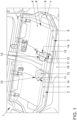
- FIG. 1 shows a simplified perspective view of a rear seat system 1 with two vehicle seats 2 and 3 arranged next to one another.
- the rear seat system 1 has a body wall 4, on which a seat part 5, 6 is arranged for each vehicle seat 2, 3.
- the seat parts 5, 6 each have a seat cover 7 (not shown here), a seat cushion 8 located beneath the seat cover, and a floor pan 9.
- the floor pan 9 rests at least partially on the body wall 4 and thus serves to hold and attach the vehicle seats 2, 3 to the body of the motor vehicle.
- the floor pan 9 also serves as a support for the seat cushion 8 and the seat cover 9.
- the seat parts 5, 6 have a common seat cushion 8, a common seat cover 7, and a common floor pan 9.
- the floor pan 9, the seat cover 7 and the seat cushion 8 thus extend over the entire width of the rear seat system 1.
- the seat parts 5, 6 are mirror images of each other and otherwise have at least essentially the same structure. The structure of both seat parts 5, 6 will now be described using the seat part 3.
- FIG 2 shows the rear seat system 1 in a perspective sectional view along the line AA from Figure 1 .
- the seat part 6 has a fan device 10 which is integrated into the seat part 6.
- the seat part 5 is assigned a correspondingly designed fan device 10, as in Figure 1 shown.
- the fan device 10 has a fan 11, which has a fan housing 12, in which a fan wheel (not shown here) can be driven by an electric motor.
- the housing 12 has a fan inlet opening 13 and a fan outlet opening 14, which is only Figure 1 shown, fan outlet opening 14.
- the fan inlet opening 13 is axially aligned with respect to the axis of rotation of the fan wheel, and the fan outlet opening 14 is at least substantially radial or tangential.
- the fan outlet opening 14 is located in the seat cushion 8, so that air conveyed by the fan 10 is conveyed into the seat cushion 8.
- the seat cushion 8 is designed to be permeable to air or has a plurality of air channels that lead from the fan outlet opening 14 to the seat cover 7, which is also permeable to air, in particular provided with a plurality of air outlet openings.
- the fan 11 is arranged at a distance from an outer edge 15 in the longitudinal extension of the seat part 6, which is formed by the seat cover 7.
- the outer edge 15 lies in In the direction of travel, the fan 11 is arranged at the front or at the front end of the seat part 6, so that the fan 11 is set back from the front outer edge of the seat part 6 in the seat part 6.
- the fan 11 when viewed from above the seat part 6, the fan 11 is not arranged in the middle, but on a long side, namely the long side of the seat part 6 facing the adjacent seat part 5.
- the fan 11 is therefore arranged in an area that is subjected to little stress when the vehicle seat 3 is in use.
- the fans 11 of both seat parts 5, 6 are arranged close to the middle of the rear seat system 1, so that they are located in an area in which a center tunnel 16 is led through the body of the motor vehicle.
- the fans are therefore located in an area in which the legs of the users of the vehicle seats 2, 3 are not usually located, so that advantageous air intake is ensured.
- the housing 12 of the fan 11 is further connected to a channel wall 17, on which the seat cushion 8 rests in some areas.
- the channel wall 17 is spaced apart from the base pan 9, so that an air channel 18 is formed between the base pan 9 and the channel wall 17, which leads to the fan inlet opening 13.
- a further channel wall 22 is arranged opposite the channel wall 17, with the channel wall 22 resting on the base pan 9, so that the air channel 18 is formed between the channel walls 17, 22.
- the channel walls 17, 22 are particularly preferably formed in one piece with one another or at least firmly connected to one another.
- FIG 3 shows a simplified sectional view of the vehicle seat 3 along the line AA from Figure 1 .
- the seat cushion 8 is also shown here, as is the seat cover 7.
- the fan 11 is arranged on the upper duct wall 17, so that the fan inlet opening 13 is formed in the duct wall 17 and the fan 11 is arranged above the air duct 18.
- the air duct 18 opens into an intake opening 19 which is formed between the floor pan 9 and the seat cushion 8.
- the intake opening 19 is formed in the area of the air duct 18 in that an edge section 20 of the floor pan 9 facing the outer edge 15 is arranged at a distance from the seat cushion 8 below the seat cushion 8.
- the edge section 20 of the floor pan 9 is inclined in such a way that the distance between the floor pan 9 and the seat cushion 8 in In the direction of the outer edge 15 of the seat cushion 8 or the seat part 6, this creates a funnel-shaped intake opening 19 when viewed in longitudinal section.
- the air duct 18 opens into the air intake opening 19 at a distance from the outer edge 15, so that the intake opening 19 extends the air duct 18 below the seat cushion 8.
- the advantageous design of the vehicle seat 3 ensures that the air is sucked in from the footwell area of the motor vehicle 1 in front of the vehicle seat 3 and is conveyed into the air cushion 8 without reversing the flow direction. This results in low flow losses and increases the efficiency of the fan device 10. Because the air duct 18 is formed between the floor pan 9 and the seat cushion 8, the air duct 18 is already manufactured together with the seat part 5 or 6, so that the seat part 5, 6 can also be placed on different or differently shaped body walls 4 of a rear seat system 1 without affecting the air guidance or air flow. Rather, it is ensured that the air duct 18 always has the desired contour and shape as well as the desired course, and that the advantageous intake opening 19 ensures efficient and safe intake of air for ventilation.
- a spring wire frame 21 is also arranged in the seat cushion 8, which extends through the seat cushion in order to increase the load-bearing capacity and rigidity of the seat cushion 8 and at the same time improve the seating comfort for passengers.
- the spring wire frame 21 is designed in such a way that it also protects the fan device 10, so that the operation of the fan device 10 is permanently guaranteed.
- At least one further fan device 10 is assigned to each seat part 5, 6, so that the achievable volume flow for ventilating a person sitting on the respective seat part 5, 6 is or can be doubled.
Landscapes
- Engineering & Computer Science (AREA)
- Aviation & Aerospace Engineering (AREA)
- Transportation (AREA)
- Mechanical Engineering (AREA)
- Chair Legs, Seat Parts, And Backrests (AREA)
Description
- Die Erfindung betrifft einen Fahrzeugsitz für eine Hintersitzanlage eines Kraftfahrzeugs, mit einem Sitzteil, das eine Bodenwanne und ein auf der Bodenwanne angeordnetes Sitzpolster aufweist, wobei die Bodenwanne dazu ausgebildet ist, auf einer Karosseriewand des Kraftfahrzeugs abgelegt und befestigt zu werden, und mit einer in das Sitzteil integrierten Lüftereinrichtung, die zumindest einen elektrisch betreibbaren Lüfter und zumindest einen von einem Randbereich des Sitzteils zu dem Lüfter führenden Luftkanal aufweist.
- Weiterhin betrifft die Erfindung eine Hintersitzanlage für ein Kraftfahrzeug, mit einer im Hintersitzbereich des Kraftfahrzeugs erhöht angeordneten und zumindest im Wesentlichen horizontal ausgerichteten Karosseriewand, und mit zumindest einem auf der Karosseriewand angeordneten Fahrzeugsitz.
- Fahrzeugsitze der eingangs genannten Art sind aus dem Stand der Technik bekannt. Lüftereinrichtungen für Fahrzeugsitze finden sich zunehmend in allen Arten von Kraftfahrzeugen. Durch sie wird eine aktive Sitzbelüftung ermöglicht, durch welche Umgebungsluft angesaugt und durch das Sitzpolster und einen Sitzbezug hindurch gefördert wird. Dazu weist beispielsweise der Sitzbezug eine Vielzahl von Luftaustrittsöffnungen auf und das Sitzpolster ist luftdurchströmbar ausgebildet. Beispielsweise die Patentschrift
DE 196 28 698 C1 offenbart einen solchen Fahrzeugsitz. Dabei ist die Luftansaugöffnung unterhalb des Sitzteils angeordnet, sodass aus dem Raum unterhalb des Sitzteils Luft angesaugt wird. Dabei erfährt der Luftstrom zum einen eine Strömungsrichtungsumkehr und zum anderen wird die Luft in einem Raum angesaugt, welcher eher staub- und schmutzbehaftet ist. Aus der OffenlegungsschriftDE 10 2011 122 124 A1 ist ein gattungsgemäßer Fahrzeugsitz bekannt, der eine Lüftereinrichtung aufweist. Ein Luftkanal ist dabei an der Unterseite der Bodenwanne, welche im montierten Zustand der Karosseriewand zugewandt ist, ausgebildet. Dabei ist der Fahrzeugsitz auf einer Karosseriewand ablegbar und eignet sich dadurch für eine Hintersitzanlage, bei welcher beispielsweise auf ein individuelles Sitzgestell verzichtet wird. - Die Offenlegungsschrift
DE 10 2011 121 331 A1 offenbart eine Sitzbelüftungseinrichtung für einen Fahrzeugsitz, mit einem Luftversorgungskanal, der einen Lüfterkanalbereich und einen damit verbundenen Versorgungskanalbereich umfasst, wobei letzterer in einer Mündungsöffnung mündet. Die Mündungsöffnung ist an einer Schmalseite einer Polsterschicht angeordnet und durch eine Abdeckung kaschiert. Sowohl der Lüfterkanalbereich als auch der damit verbundene Versorgungskanalbereich verlaufen vollständig innerhalb der Polsterschicht. Aus den OffenlegungsschriftenUS 2019 / 210 492 A1 ,DE 10 2015 210 624 A1 undUS 2018 / 272 908 A1 sind weitere Fahrzeugsitze mit Lüftereinrichtungen bekannt. - Der Erfindung liegt die Aufgabe zugrunde, einen verbesserten Fahrzeugsitz zu schaffen, der eine verbesserte Luftführung für die Lüftereinrichtung gewährleistet, ohne hierzu einen Material- oder Kostenmehraufwand zu benötigen.
- Die der Erfindung zugrundeliegende Aufgabe wird durch einen Fahrzeugsitz mit den Merkmalen des Anspruchs 1 gelöst. Dieser hat den Vorteil, dass er trotz der Ausbildung für eine Hintersitzanlage eine vorteilhafte Luftansaugung gewährleistet, die geringe Strömungsverluste verursacht und dennoch von außen für den Benutzer nicht ohne weiteres erkennbar ist. Erfindungsgemäß ist hierzu vorgesehen, dass der Luftkanal zumindest im Wesentlichen zwischen dem Sitzpolster und der Bodenwanne ausgebildet ist, dass die Bodenwanne in dem Randbereich einen Randabschnitt aufweist, der beabstandet zu dem Sitzpolster angeordnet ist, um eine Ansaugöffnung zu bilden, und dass der Luftkanal in die Ansaugöffnung beabstandet von einem Außenrand des Sitzpolsters mündet. Der Randabschnitt der Bodenwanne liegt also beabstandet zu dem Sitzpolster, sodass zwischen Sitzpolster und Randabschnitt eine Ansaugöffnung gebildet ist, die dem Zuführen der Luft zum Belüften dient. Weil die Bodenwanne unterhalb des Sitzteils liegt, wird durch den Abstand des Randabschnitts zu dem Sitzpolster ein Abstand in der Höhe (bei bestimmungsgemäßer Montage) erreicht, sodass die Ansaugöffnung unterhalb des Sitzpolsters liegt. Weil der Luftkanal beabstandet zu dem Außenrand des Sitzpolsters in die Ansaugöffnung mündet, ist der Luftkanal von außen zum einen nicht ersichtlich, und zum anderen bildet die Ansaugöffnung eine Verlängerung des Luftkanals, die jedoch, wie zuvor bereits beschrieben, unterhalb des Sitzpolsters liegt. Dadurch, dass der Luftkanal in die Ansaugöffnung übergeht, und diese dem Randabschnitt beziehungsweise dem Randbereich des Fahrzeugsitzes, insbesondere des Sitzteils, zugewandt ist, ergibt sich eine Luftstromförderrichtung, die Luft aus dem Bereich vor dem Fahrzeugsitz und nicht unterhalb des Fahrzeugsitzes ansaugt. Insbesondere weist der Fahrzeugsitz außerdem eine dem Sitzteil zugeordnete Rückenlehne auf, die beispielsweise fest oder verschwenkbar an dem Sitzteil, an dem in Längsrichtung von der Ansaugöffnung abgewandten Ende des Sitzteils gelagert ist. Bei der Verwendung in einer Hintersitzanlage wäre ein Ansaugen unterhalb des Fahrzeugsitzes nur mit erhöhtem Aufwand möglich, weil durch die darunterliegende Karosseriewand der Raum unterhalb des Sitzteils üblicherweise geschlossen ist. Durch die vorteilhafte Ausbildung des Fahrzeugsitzes ergibt sich somit auch der Vorteil, dass dieser auch bei der Verwendung in eine Hintersitzanlage einen vorteilhaften Luftstrom zum Belüften eines Passagiers beziehungsweise eines Benutzers des Fahrzeugsitzes gewährleistet.
- Besonders bevorzugt sind der Luftkanal und die Ansaugöffnung derart ausgebildet, dass ein Luftstrom von der Ansaugöffnung zu dem Lüfter strömungsumkehrfrei gelangt. Es folgt somit keine Strömungsumkehr im Strömungsverlauf des Luftstroms von der Ansaugöffnung zu dem Lüfter, wodurch Strömungsverluste vermieden und hohe Luftstromvolumen erreicht werden.
- Bevorzugt ist der Randabschnitt der Bodenwanne derart ausgerichtet, dass ein Abstand zwischen Sitzpolster und Bodenwanne zu dem Außenrand des Sitzpolsters hin zunimmt. Der Randabschnitt ist somit im montierten Zustand des Fahrzeugsitzes nach unten geneigt, sodass ein freies Ende tiefer angeordnet ist, als das dem Luftkanal zugewandte Ende. Hierdurch entsteht im Bereich der Ansaugöffnung ein Ansaugtrichter, der eine verbesserte Luftansaugung und Zuführung erlaubt.
- Besonders bevorzugt ist der Lüfter beabstandet zu dem Randabschnitt in dem Luftkanal angeordnet, sodass der Lüfter beispielsweise weiter im hinteren Bereich oder zumindest beabstandet vom Außenrand des Sitzpolsters angeordnet ist, um Komfortvorteile zu erzielen, dadurch, dass der Lüfter in einem Bereich liegt, der durch das Sitzpolster besser oder stärker geschützt ist.
- Weiterhin ist bevorzugt vorgesehen, dass der Lüfter auf der von der Bodenwanne abgewandten Seite des Luftkanals angeordnet ist. Der Lüfter liegt somit oberhalb des Luftkanals und saugt die Luft von der Ansaugöffnung an und fördert diese direkt nach oben in das Sitzpolster beziehungsweise durch das Sitzpolster und einen optionalen Sitzbezug hindurch. Hierdurch ergibt sich eine vorteilhafte, insbesondere bauraumsparende Anordnung des Lüfters in dem Sitzteil.
- Weiterhin ist bevorzugt vorgesehen, dass der Luftkanal zumindest auf der Seite des Luftpolsters eine das Luftpolster stützende Kanalwand aufweist. Durch die Kanalwand ist gewährleistet, dass der Luftkanal nicht durch eine Belastung des Sitzpolsters verengt oder einstürzen kann. Durch die Kanalwand wird somit der Durchströmungsquerschnitt des Luftkanals zu jeder Zeit sichergestellt.
- Der Lüfter weist bevorzugt ein Gehäuse auf, das mit der Kanalwand verbunden ist. Dadurch ist zum einen ein sicherer und strömungsoptimierter Fluss des Luftstroms von dem Luftkanal in das Gehäuse des Lüfters gewährleistet, und zum anderen eine einfache Montage der Lüftereinrichtung geboten. Insbesondere können der Luftkanal beziehungsweise die Kanalwand und das Gehäuse des Lüfters als Vormontageeinheit ausgebildet sein, um dann gemeinsam an dem Sitzpolster und/oder der Bodenwanne angeordnet und/oder befestigt zu werden.
- Vorzugsweise ist in dem Sitzpolster ein Drahtrahmen, insbesondere ein Federradrahmen angeordnet, welcher zur Federung und damit zur Komfortsteigerung des Sitzteils dient. Der Drahtrahmen ist bevorzugt um die Lüftereinrichtung herum geführt, sodass sich der Drahtrahmen und das Gehäuse des Lüfters sowie die Kanalwand des Luftkanals nicht treffen. Dadurch ist eine vorteilhafte Integration der Federung in das Sitzpolster gewährleistet.
- Die erfindungsgemäße Hintersitzanlage mit den Merkmalen des Anspruchs 9 zeichnet sich durch die erfindungsgemäße Ausbildung des Fahrzeugsitzes aus. Es ergeben sich hierdurch die bereits genannten Vorteile.
- Bevorzugt ist die Lüftereinrichtung einer Längsseite des Sitzteils zugeordnet. Damit liegt die Lüftereinrichtung bei einer Draufsicht auf das Sitzteil gesehen, außermittig und damit in einem Bereich, der durch einen Benutzer weniger stark belastet wird, sodass ein optimaler Sitzkomfort gewährleistet ist. Darüber hinaus liegt damit auch die Ansaugöffnung außermittig, sodass Luft mit hoher Wahrscheinlichkeit aus einem Bereich angesaugt wird, in welchem sich die Beine des Benutzers bei einer normalen Sitzstellung erwartungsgemäß nicht befinden. Besonders bevorzugt ist jeder Längsseite des Sitzteils jeweils eine entsprechend ausgebildete Lüftereinrichtung zugeordnet, sodass das Luftfördervolumen verdoppelt und eine verbesserte Belüftung des Benutzers des Fahrzeugsitzes gewährleistet ist.
- Im Folgenden soll die Erfindung anhand der Zeichnungen näher erläutert werden. Dazu zeigen
- Figur 1
- eine perspektivische Darstellung einer vorteilhaften Hintersitzanlage eines Kraftfahrzeugs,
- Figur 2
- eine perspektivische Schnittdarstellung eines Fahrzeugsitzes der Hintersitzanlage und
- Figur 3
- eine Längsschnittdarstellung des Fahrzeugsitzes.
-
Figur 1 zeigt in einer vereinfachten perspektivischen Darstellung eine Hintersitzanlage 1 mit zwei Fahrzeugsitzen 2 und 3, die nebeneinander angeordnet sind. Die Hintersitzanlage 1 weist eine Karosseriewand 4 auf, auf welcher von jedem Fahrzeugsitz 2, 3 jeweils ein Sitzteil 5, 6 angeordnet ist. Die Sitzteile 5, 6 weisen jeweils einen hier nicht dargestellten Sitzbezug 7, ein unterhalb des Sitzbezugs befindliches Sitzpolster 8 sowie eine Bodenwanne 9 auf. Die Bodenwanne 9 liegt zumindest bereichsweise auf der Karosseriewand 4 auf und dient damit zur Halterung und Befestigung der Fahrzeugsitze 2, 3 an der Karosserie des Kraftfahrzeugs. Die Bodenwanne 9 dient außerdem als Träger für das Sitzpolster 8 und den Sitzbezug 9. Gemäß dem vorliegenden Ausführungsbeispiel weisen die Sitzteile 5, 6 ein gemeinsames Sitzpolster 8 sowie einen gemeinsamen Sitzbezug 7 sowie eine gemeinsame Bodenwanne 9 auf. Die Bodenwanne 9, der Sitzbezug 7 und das Sitzpolster 8 erstrecken sich somit über die gesamte Breite der Hintersitzanlage 1. Die Sitzteile 5, 6 sind spiegelbildlich zueinander und ansonsten zumindest im Wesentlichen gleich aufgebaut. Anhand des Sitzteils 3 soll nunmehr der Aufbau beider Sitzteile 5, 6 beschrieben werden. -
Figur 2 zeigt die Hintersitzanlage 1 in einer perspektivischen Schnittdarstellung entlang der Linie A-A ausFigur 1 . Das Sitzteil 6 weist eine Lüftereinrichtung 10 auf, die in das Sitzteil 6 integriert ausgebildet ist. Dem Sitzteil 5 ist eine entsprechend ausgebildete Lüftereinrichtung 10 zugeordnet, wie inFigur 1 gezeigt. Die Lüftereinrichtung 10 weist einen Lüfter 11 auf, der ein Lüfter-Gehäuse 12 aufweist, in welchem ein hier nicht dargestelltes Lüfterrad elektromotorisch antreibbar ist. Das Gehäuse 12 weist eine Lüftereinlassöffnung 13 sowie eine, lediglich inFigur 1 gezeigte, Lüfteraustrittsöffnung 14 auf. Die Lüftereintrittsöffnung 13 ist axial ausgerichtet bezogen auf die Drehachse des Lüfterrads, und die Lüfteraustrittsöffnung 14 zumindest im Wesentlichen radial oder tangential. Die Lüfteraustrittsöffnung 14 liegt dabei in dem Sitzpolster 8, sodass durch den Lüfter 10 geförderte Luft in das Sitzpolster 8 gefördert wird. Das Sitzpolster 8 ist luftdurchlässig ausgebildet oder weist eine Mehrzahl von Luftkanälen auf, die von der Lüfteraustrittsöffnung 14 zu dem ebenfalls luftdurchlässig, insbesondere mit einer Vielzahl von Luftaustrittsöffnungen versehenen Sitzbezug 7 führen. - Der Lüfter 11 ist beabstandet von einem Außenrand 15 in Längserstreckung des Sitzteils 6 angeordnet, das von dem Sitzbezug 7 gebildet wird. Der Außenrand 15 liegt dabei in Fahrtrichtung vorne beziehungsweise am vorderen Ende des Sitzteils 6, sodass der Lüfter 11 zurückgesetzt von dem vorderen Außenrand des Sitzteils 6 in dem Sitzteil 6 angeordnet ist. Darüber hinaus ist der Lüfter 11 in einer Draufsicht des Sitzteils 6 betrachtet, nicht mittig, sondern einer Längsseite, nämlich der dem benachbarten Sitzteil 5 zugewandten Längsseite des Sitzteils 6 angeordnet. Damit ist der Lüfter 11 insgesamt in einem Bereich angeordnet, der bei Benutzung des Fahrzeugsitzes 3 eher wenig belastet ist. Gemäß dem vorliegenden Ausführungsbeispiel liegen die Lüfter 11 beider Sitzteile 5, 6 nahe zur Mitte der Hintersitzanlage 1 hin angeordnet, sodass sie in einem Bereich liegen, in welchem ein Mitteltunnel 16 durch die Karosserie des Kraftfahrzeugs geführt ist. Damit liegen die Lüfter in einem Bereich, in welchem üblicherweise die Beine von den Benutzern der Fahrzeugsitze 2, 3 nicht liegen, sodass eine vorteilhafte Luftansaugung gewährleistet ist.
- Das Gehäuse 12 des Lüfters 11 ist des Weiteren mit einer Kanalwand 17 verbunden, auf welcher das Sitzpolster 8 bereichsweise aufliegt. Die Kanalwand 17 liegt beabstandet zu der Bodenwanne 9, sodass zwischen der Bodenwanne 9 und der Kanalwand 17 ein Luftkanal 18 gebildet ist, der zu der Lüftereintrittsöffnung 13 führt. Optional ist der Kanalwand 17 eine weitere Kanalwand 22 gegenüberliegend angeordnet, wobei die Kanalwand 22 auf der Bodenwanne 9 aufliegt, sodass der Luftkanal 18 zwischen den Kanalwänden 17, 22 ausgebildet ist. Besonders bevorzugt sind die Kanalwände 17, 22 einstückig miteinander ausgebildet oder zumindest fest miteinander verbunden.
-
Figur 3 zeigt zum leichteren Verständnis eine vereinfachte Schnittdarstellung des Fahrzeugsitzes 3 entlang der Linie A-A ausFigur 1 . Hierbei ist das Sitzpolster 8 ebenfalls eingezeichnet, ebenso wie der Sitzbezug 7. Der Lüfter 11 ist an der oberen Kanalwand 17 angeordnet, sodass die Lüftereintrittsöffnung 13 in der Kanalwand 17 ausgebildet und der Lüfter 11 oberhalb des Luftkanals 18 angeordnet ist. An seinem von dem Lüfter 11 abgewandten Ende mündet der Luftkanal 18 in eine Ansaugöffnung 19, die zwischen der Bodenwanne 9 und dem Sitzpolster 8 ausgebildet ist. Während im Wesentlichen das Sitzpolster 8 auf der Bodenwanne 9 aufliegt, abgesehen vom Bereich der Lüftereinrichtung 10, wobei das Sitzpolster 8 insbesondere auch seitlich benachbart zu der Lüftereinrichtung an seinem Außenrand 15 auf der Bodenwanne aufliegt, wird im Bereich des Luftkanals 18 die Ansaugöffnung 19 dadurch gebildet, dass ein dem Außenrand 15 zugewandter Randabschnitt 20 der Bodenwanne 9 beabstandet zu dem Sitzpolster 8 unterhalb des Sitzpolsters 8 angeordnet ist. Dadurch entsteht ein Spalt zwischen der Bodenwanne 9 und dem Sitzpolster 8, der die Ansaugöffnung 19 bildet. Gemäß dem vorliegenden Ausführungsbeispiel ist der Randabschnitt 20 der Bodenwanne 9 derart geneigt ausgebildet, dass der Abstand zwischen Bodenwanne 9 und Sitzpolster 8 in Richtung des Außenrands 15 des Sitzpolsters 8 beziehungsweise des Sitzteils 6 zunimmt. Dadurch entsteht eine im Längsschnitt gesehen trichterförmige Ansaugöffnung 19. Der Luftkanal 18 mündet in die Luft-Ansaugöffnung 19 beabstandet zu dem Außenrand 15, sodass die Ansaugöffnung 19 den Luftkanal 18 unterhalb des Sitzpolsters 8 verlängert. - Durch die vorteilhafte Ausbildung des Fahrzeugsitzes 3 ist gewährleistet, dass die Luft aus dem vor dem Fahrzeugsitz 3 liegenden Fußraumbereich des Kraftfahrzeugs 1 angesaugt und ohne Strömungsrichtungsumkehr in das Luftpolster 8 hinein gefördert wird. Dadurch werden geringe Strömungsverluste erreicht und die Effizienz der Lüftereinrichtung 10 erhöht. Dadurch, dass der Luftkanal 18 zwischen der Bodenwanne 9 und dem Sitzpolster 8 ausgebildet ist, wird der Luftkanal 18 zusammen mit dem Sitzteil 5 beziehungsweise 6 bereits mitgefertigt, sodass das Sitzteil 5, 6 auch auf unterschiedlichen beziehungsweise unterschiedlich geformten Karosseriewänden 4 einer Hintersitzanlage 1 aufsetzbar ist, ohne dass dadurch die Luftführung oder Luftströmung beeinträchtigt wird. Vielmehr wird sichergestellt, dass der Luftkanal 18 stets die gewünschte Kontur und Form sowie den gewünschten Verlauf aufweist, und dass durch die vorteilhafte Ansaugöffnung 19 ein effizientes und sicheres Ansaugen von Luft zum Belüften gewährleistet ist.
- Optional ist in dem Sitzpolster 8 außerdem ein Federdrahtrahmen 21 angeordnet, der sich durch das Sitzpolster erstreckt, um die Belastbarkeit und Steifheit des Sitzpolsters 8 zu erhöhen und gleichzeitig den Sitzkomfort für Passagiere zu verbessern. Der Federdrahtrahmen 21 ist dabei derart ausgebildet, dass er auch die Lüftereinrichtung 10 schützt, sodass der Betrieb der Lüftereinrichtung 10 dauerhaft gewährleistet ist.
- Optional, in den Figuren jedoch nicht dargestellt, ist jedem Sitzteil 5, 6 zumindest eine weitere Lüftereinrichtung 10 zugeordnet, sodass der erreichbare Volumenstrom zum Belüften einer auf dem jeweiligen Sitzteil 5, 6 befindlichen Person verdoppelt wird oder verdoppelt werden kann.
-
- 1
- Hintersitzanlage
- 2
- Fahrzeugsitz
- 3
- Fahrzeugsitz
- 4
- Karosseriewand
- 5
- Sitzteil
- 6
- Sitzteil
- 7
- Sitzbezug
- 8
- Sitzpolster
- 9
- Bodenwanne
- 10
- Lüftereinrichtung
- 11
- Lüfter
- 12
- Lüfter-Gehäuse
- 13
- Lüftereinlassöffnung
- 14
- Lüfterauslassöffnung
- 15
- Außenrand
- 16
- Mitteltunnel
- 17
- Kanalwand
- 18
- Luftkanal
- 19
- Ansaugöffnung
- 20
- Randabschnitt
- 21
- Federdrahtrahmen
- 22
- Kanalwand
Claims (10)
- Fahrzeugsitz (2,3) für eine Hintersitzanlage (1) eines Kraftfahrzeugs, mit einem Sitzteil (5,6), das eine Bodenwanne (9) und ein auf der Bodenwanne (9) angeordnetes Sitzpolster (8) aufweist, wobei die Bodenwanne (9) dazu ausgebildet ist, auf einer Karosseriewand (4) des Kraftfahrzeugs abgelegt und befestigt zu werden, und mit einer in das Sitzteil (5,6) integrierten Lüftereinrichtung (10), die zumindest einen elektrisch betreibbaren Lüfter (11) und zumindest einen von einem Randbereich des Sitzteils (5,6) zu dem Lüfter (11) führenden Luftkanal (18) aufweist, wobei der Luftkanal (18) ist zumindest im Wesentlichen zwischen dem Sitzpolster (8) und der Bodenwanne (9) ausgebildet die Bodenwanne (9) aufweist in dem Randbereich einen Randabschnitt (20) , der beabstandet zu dem Sitzpolster (8) unterhalb des Sitzpolsters (8) angeordnet ist, um einen Spalt zwischen der Bodenwanne (9) und dem Sitzpolster (8) als eine Ansaugöffnung (19) zu bilden, und der Luftkanal (18) mündet in die Ansaugöffnung (19) beabstandet von einem Außenrand (15) des Sitzpolsters (8) , sodass die Ansaugöffnung (19) den Luftkanal (18) unterhalb des Sitzpolsters (8) verlängert.
- Fahrzeugsitz nach Anspruch 1, dadurch gekennzeichnet, dass der Randabschnitt (20) der Bodenwanne (9) derart ausgerichtet ist, dass ein Abstand zwischen Sitzpolster (8) und Bodenwanne (9) zu dem Außenrand (15) des Sitzpolsters (8) hin zunimmt.
- Fahrzeugsitz nach einem der vorhergehenden Ansprüche, dadurch gekennzeichnet, dass der Lüfter (11) beabstandet zu dem Randabschnitt (20) in dem Luftkanal (18) angeordnet ist.
- Fahrzeugsitz nach einem der vorhergehenden Ansprüche, dadurch gekennzeichnet, dass der Luftkanal (18) und die Ansaugöffnung (19) derart ausgebildet sind, dass ein Luftstrom von der Ansaugöffnung (19) zu dem Lüfter (11) strömungsumkehrfrei gelangt.
- Fahrzeugsitz nach einem der vorhergehenden Ansprüche, dadurch gekennzeichnet, dass der Lüfter (11) auf der von der Bodenwanne (9) abgewandten Seite des Luftkanals (18) angeordnet ist.
- Fahrzeugsitz nach einem der vorhergehenden Ansprüche, dadurch gekennzeichnet, dass der Luftkanal (18) zumindest auf der Seite des Sitzpolsters (8) eine das Sitzpolster (8) stützende Kanalwand (17) aufweist.
- Fahrzeugsitz nach einem der vorhergehenden Ansprüche, dadurch gekennzeichnet, dass der Lüfter (11) ein Gehäuse (12) aufweist, das mit der Kanalwand (17) verbunden ist.
- Fahrzeugsitz nach einem der vorhergehenden Ansprüche, dadurch gekennzeichnet, dass in dem Sitzpolster (8) ein Drahtrahmen, insbesondere Federdrahtrahmen (21), angeordnet ist.
- Hintersitzanlage (1) für ein Kraftfahrzeug, mit einer im Hintersitzbereich erhöht angeordneten und zumindest im Wesentlichen horizontal ausgerichteten Karosseriewand (4), und mit zumindest einem auf der Karosseriewand (4) angeordneten Fahrzeugsitz (2,3), dadurch gekennzeichnet, dass der Fahrzeugsitz (2,3) gemäß einem der Ansprüche 1 bis 8 ausgebildet ist.
- Hintersitzanlage nach Anspruch 9, dadurch gekennzeichnet, dass die Lüftereinrichtung (10) einer Längsseite des Sitzteils (5,6) zugeordnet ist.
Applications Claiming Priority (2)
| Application Number | Priority Date | Filing Date | Title |
|---|---|---|---|
| DE102019212992.7A DE102019212992A1 (de) | 2019-08-29 | 2019-08-29 | Fahrzeugsitz und Hintersitzanlage |
| PCT/EP2020/073696 WO2021037825A1 (de) | 2019-08-29 | 2020-08-25 | Fahrzeugsitz und hintersitzanlage mit lüftereinrichtung |
Publications (2)
| Publication Number | Publication Date |
|---|---|
| EP4021759A1 EP4021759A1 (de) | 2022-07-06 |
| EP4021759B1 true EP4021759B1 (de) | 2025-01-22 |
Family
ID=72291008
Family Applications (1)
| Application Number | Title | Priority Date | Filing Date |
|---|---|---|---|
| EP20764328.9A Active EP4021759B1 (de) | 2019-08-29 | 2020-08-25 | Fahrzeugsitz und hintersitzanlage mit lüftereinrichtung |
Country Status (4)
| Country | Link |
|---|---|
| EP (1) | EP4021759B1 (de) |
| CN (1) | CN114269600A (de) |
| DE (1) | DE102019212992A1 (de) |
| WO (1) | WO2021037825A1 (de) |
Citations (1)
| Publication number | Priority date | Publication date | Assignee | Title |
|---|---|---|---|---|
| US20200130548A1 (en) * | 2017-03-24 | 2020-04-30 | Ts Tech Co., Ltd. | Vehicle seat |
Family Cites Families (11)
| Publication number | Priority date | Publication date | Assignee | Title |
|---|---|---|---|---|
| DE19628698C1 (de) * | 1996-07-17 | 1997-10-09 | Daimler Benz Ag | Fahrzeugsitz |
| DE10261268B4 (de) * | 2002-04-09 | 2006-09-14 | Gerhard Pfeil | Belüftetes Liege- oder Sitzmöbel |
| DE102011122124C5 (de) * | 2011-01-06 | 2020-04-09 | I.G. Bauerhin Gmbh | Fahrzeugsitz |
| DE102011121331A1 (de) * | 2011-12-16 | 2012-06-21 | Daimler Ag | Polster für einen Fahrzeugsitz |
| DE102012006074A1 (de) * | 2012-03-24 | 2012-11-08 | Daimler Ag | Kraftfahrzeugsitz |
| DE202012010708U1 (de) * | 2012-11-09 | 2012-11-28 | I.G. Bauerhin Gmbh | Baugruppe für die Klimatisierung eines Fahrzeugsitzes |
| CN106163866B (zh) * | 2014-04-11 | 2018-10-16 | 提爱思科技股份有限公司 | 交通工具用座椅 |
| DE102015213299A1 (de) * | 2014-08-28 | 2016-03-17 | Mahle International Gmbh | Personenkraftwagen mit belüftetem Fondfußraum |
| EP3006262B1 (de) * | 2014-10-07 | 2016-11-23 | C.R.F. Società Consortile per Azioni | Kraftfahrzeugsitz mit einem System zur Zuführung von klimatisierter Luft |
| DE102015210624A1 (de) * | 2015-06-10 | 2016-12-15 | Bombardier Transportation Gmbh | Schienenfahrzeug mit Klimatisierung über Sitze |
| US10780799B2 (en) * | 2016-09-05 | 2020-09-22 | Adient Luxembourg Holding S.À R.L. | Vehicle seat and vehicle |
-
2019
- 2019-08-29 DE DE102019212992.7A patent/DE102019212992A1/de not_active Withdrawn
-
2020
- 2020-08-25 WO PCT/EP2020/073696 patent/WO2021037825A1/de not_active Ceased
- 2020-08-25 CN CN202080060855.7A patent/CN114269600A/zh active Pending
- 2020-08-25 EP EP20764328.9A patent/EP4021759B1/de active Active
Patent Citations (1)
| Publication number | Priority date | Publication date | Assignee | Title |
|---|---|---|---|---|
| US20200130548A1 (en) * | 2017-03-24 | 2020-04-30 | Ts Tech Co., Ltd. | Vehicle seat |
Also Published As
| Publication number | Publication date |
|---|---|
| WO2021037825A1 (de) | 2021-03-04 |
| CN114269600A (zh) | 2022-04-01 |
| DE102019212992A1 (de) | 2021-03-04 |
| EP4021759A1 (de) | 2022-07-06 |
Similar Documents
| Publication | Publication Date | Title |
|---|---|---|
| DE10243315B4 (de) | Polster für einen Fahrzeugsitz | |
| DE10259621B4 (de) | Fahrzeugsitz und zugehörige Klimatisierungseinrichtung | |
| EP1323574A2 (de) | Kraftfahrzeugsitz | |
| DE102012006074A1 (de) | Kraftfahrzeugsitz | |
| DE19745521A1 (de) | Polster für einen Fahrzeugsitz | |
| DE10163050A1 (de) | Kopfstütze für einen Kraftfahrzeugsitz | |
| DE202012010708U1 (de) | Baugruppe für die Klimatisierung eines Fahrzeugsitzes | |
| DE102011122124B4 (de) | Fahrzeugsitz | |
| DE102018222477A1 (de) | Kindersitzanordnung | |
| DE102009052683A1 (de) | Fahrzeugsitz mit einer Luftversorgungseinrichtung | |
| EP3873774B1 (de) | Fahrzeugsitz für ein kraftfahrzeug | |
| DE102016205935A1 (de) | Kraftfahrzeug | |
| EP4021759B1 (de) | Fahrzeugsitz und hintersitzanlage mit lüftereinrichtung | |
| DE102011109570A1 (de) | Lüftermodul für eine Sitzbelüftungseinrichtung einer Sitzanlage sowie Polsterteil einer Sitzanlage | |
| DE4126518C2 (de) | Fahrzeugsitz | |
| DE19941715C1 (de) | Polster für einen Fahrzeugsitz | |
| DE102005003849B3 (de) | Fahrzeugsitz mit Belüftungsvorrichtung | |
| DE10059358A1 (de) | Fahrzeugsitz mit Lüftung | |
| DE19906987B4 (de) | Rahmen für die Rückenlehne eines Fahrzeugsitzes | |
| EP3456582A1 (de) | Klimasitz | |
| DE102005015238B4 (de) | Funktionssystem | |
| EP2258584B1 (de) | Rückenlehne für einen Fahrzeugsitz | |
| EP1213171A2 (de) | Windschott-Anordnung für offene Kraftfahrzeuge | |
| DE102012025365B4 (de) | Sitz, insbesondere Fahrzeugsitz | |
| DE102008047546A1 (de) | Kraftfahrzeug |
Legal Events
| Date | Code | Title | Description |
|---|---|---|---|
| STAA | Information on the status of an ep patent application or granted ep patent |
Free format text: STATUS: UNKNOWN |
|
| STAA | Information on the status of an ep patent application or granted ep patent |
Free format text: STATUS: THE INTERNATIONAL PUBLICATION HAS BEEN MADE |
|
| PUAI | Public reference made under article 153(3) epc to a published international application that has entered the european phase |
Free format text: ORIGINAL CODE: 0009012 |
|
| STAA | Information on the status of an ep patent application or granted ep patent |
Free format text: STATUS: REQUEST FOR EXAMINATION WAS MADE |
|
| 17P | Request for examination filed |
Effective date: 20220329 |
|
| AK | Designated contracting states |
Kind code of ref document: A1 Designated state(s): AL AT BE BG CH CY CZ DE DK EE ES FI FR GB GR HR HU IE IS IT LI LT LU LV MC MK MT NL NO PL PT RO RS SE SI SK SM TR |
|
| DAV | Request for validation of the european patent (deleted) | ||
| DAX | Request for extension of the european patent (deleted) | ||
| GRAP | Despatch of communication of intention to grant a patent |
Free format text: ORIGINAL CODE: EPIDOSNIGR1 |
|
| STAA | Information on the status of an ep patent application or granted ep patent |
Free format text: STATUS: GRANT OF PATENT IS INTENDED |
|
| INTG | Intention to grant announced |
Effective date: 20241010 |
|
| GRAS | Grant fee paid |
Free format text: ORIGINAL CODE: EPIDOSNIGR3 |
|
| GRAA | (expected) grant |
Free format text: ORIGINAL CODE: 0009210 |
|
| STAA | Information on the status of an ep patent application or granted ep patent |
Free format text: STATUS: THE PATENT HAS BEEN GRANTED |
|
| AK | Designated contracting states |
Kind code of ref document: B1 Designated state(s): AL AT BE BG CH CY CZ DE DK EE ES FI FR GB GR HR HU IE IS IT LI LT LU LV MC MK MT NL NO PL PT RO RS SE SI SK SM TR |
|
| REG | Reference to a national code |
Ref country code: GB Ref legal event code: FG4D Free format text: NOT ENGLISH |
|
| REG | Reference to a national code |
Ref country code: CH Ref legal event code: EP |
|
| REG | Reference to a national code |
Ref country code: IE Ref legal event code: FG4D Free format text: LANGUAGE OF EP DOCUMENT: GERMAN |
|
| REG | Reference to a national code |
Ref country code: DE Ref legal event code: R096 Ref document number: 502020010281 Country of ref document: DE |
|
| P01 | Opt-out of the competence of the unified patent court (upc) registered |
Free format text: CASE NUMBER: APP_10661/2025 Effective date: 20250304 |
|
| REG | Reference to a national code |
Ref country code: NL Ref legal event code: MP Effective date: 20250122 |
|
| PG25 | Lapsed in a contracting state [announced via postgrant information from national office to epo] |
Ref country code: NL Free format text: LAPSE BECAUSE OF FAILURE TO SUBMIT A TRANSLATION OF THE DESCRIPTION OR TO PAY THE FEE WITHIN THE PRESCRIBED TIME-LIMIT Effective date: 20250122 |
|
| PG25 | Lapsed in a contracting state [announced via postgrant information from national office to epo] |
Ref country code: RS Free format text: LAPSE BECAUSE OF FAILURE TO SUBMIT A TRANSLATION OF THE DESCRIPTION OR TO PAY THE FEE WITHIN THE PRESCRIBED TIME-LIMIT Effective date: 20250422 |
|
| PG25 | Lapsed in a contracting state [announced via postgrant information from national office to epo] |
Ref country code: FI Free format text: LAPSE BECAUSE OF FAILURE TO SUBMIT A TRANSLATION OF THE DESCRIPTION OR TO PAY THE FEE WITHIN THE PRESCRIBED TIME-LIMIT Effective date: 20250122 |
|
| PG25 | Lapsed in a contracting state [announced via postgrant information from national office to epo] |
Ref country code: PL Free format text: LAPSE BECAUSE OF FAILURE TO SUBMIT A TRANSLATION OF THE DESCRIPTION OR TO PAY THE FEE WITHIN THE PRESCRIBED TIME-LIMIT Effective date: 20250122 |
|
| PG25 | Lapsed in a contracting state [announced via postgrant information from national office to epo] |
Ref country code: ES Free format text: LAPSE BECAUSE OF FAILURE TO SUBMIT A TRANSLATION OF THE DESCRIPTION OR TO PAY THE FEE WITHIN THE PRESCRIBED TIME-LIMIT Effective date: 20250122 |
|
| REG | Reference to a national code |
Ref country code: LT Ref legal event code: MG9D |
|
| PG25 | Lapsed in a contracting state [announced via postgrant information from national office to epo] |
Ref country code: NO Free format text: LAPSE BECAUSE OF FAILURE TO SUBMIT A TRANSLATION OF THE DESCRIPTION OR TO PAY THE FEE WITHIN THE PRESCRIBED TIME-LIMIT Effective date: 20250422 Ref country code: IS Free format text: LAPSE BECAUSE OF FAILURE TO SUBMIT A TRANSLATION OF THE DESCRIPTION OR TO PAY THE FEE WITHIN THE PRESCRIBED TIME-LIMIT Effective date: 20250522 |
|
| PG25 | Lapsed in a contracting state [announced via postgrant information from national office to epo] |
Ref country code: HR Free format text: LAPSE BECAUSE OF FAILURE TO SUBMIT A TRANSLATION OF THE DESCRIPTION OR TO PAY THE FEE WITHIN THE PRESCRIBED TIME-LIMIT Effective date: 20250122 |
|
| PG25 | Lapsed in a contracting state [announced via postgrant information from national office to epo] |
Ref country code: LV Free format text: LAPSE BECAUSE OF FAILURE TO SUBMIT A TRANSLATION OF THE DESCRIPTION OR TO PAY THE FEE WITHIN THE PRESCRIBED TIME-LIMIT Effective date: 20250122 Ref country code: PT Free format text: LAPSE BECAUSE OF FAILURE TO SUBMIT A TRANSLATION OF THE DESCRIPTION OR TO PAY THE FEE WITHIN THE PRESCRIBED TIME-LIMIT Effective date: 20250522 |
|
| PG25 | Lapsed in a contracting state [announced via postgrant information from national office to epo] |
Ref country code: BG Free format text: LAPSE BECAUSE OF FAILURE TO SUBMIT A TRANSLATION OF THE DESCRIPTION OR TO PAY THE FEE WITHIN THE PRESCRIBED TIME-LIMIT Effective date: 20250122 Ref country code: GR Free format text: LAPSE BECAUSE OF FAILURE TO SUBMIT A TRANSLATION OF THE DESCRIPTION OR TO PAY THE FEE WITHIN THE PRESCRIBED TIME-LIMIT Effective date: 20250423 |
|
| PG25 | Lapsed in a contracting state [announced via postgrant information from national office to epo] |
Ref country code: SE Free format text: LAPSE BECAUSE OF FAILURE TO SUBMIT A TRANSLATION OF THE DESCRIPTION OR TO PAY THE FEE WITHIN THE PRESCRIBED TIME-LIMIT Effective date: 20250122 |
|
| PG25 | Lapsed in a contracting state [announced via postgrant information from national office to epo] |
Ref country code: SM Free format text: LAPSE BECAUSE OF FAILURE TO SUBMIT A TRANSLATION OF THE DESCRIPTION OR TO PAY THE FEE WITHIN THE PRESCRIBED TIME-LIMIT Effective date: 20250122 |
|
| PG25 | Lapsed in a contracting state [announced via postgrant information from national office to epo] |
Ref country code: DK Free format text: LAPSE BECAUSE OF FAILURE TO SUBMIT A TRANSLATION OF THE DESCRIPTION OR TO PAY THE FEE WITHIN THE PRESCRIBED TIME-LIMIT Effective date: 20250122 |
|
| PGFP | Annual fee paid to national office [announced via postgrant information from national office to epo] |
Ref country code: DE Payment date: 20250831 Year of fee payment: 6 |
|
| PG25 | Lapsed in a contracting state [announced via postgrant information from national office to epo] |
Ref country code: IT Free format text: LAPSE BECAUSE OF FAILURE TO SUBMIT A TRANSLATION OF THE DESCRIPTION OR TO PAY THE FEE WITHIN THE PRESCRIBED TIME-LIMIT Effective date: 20250122 |
|
| PGFP | Annual fee paid to national office [announced via postgrant information from national office to epo] |
Ref country code: GB Payment date: 20250826 Year of fee payment: 6 |
|
| PGFP | Annual fee paid to national office [announced via postgrant information from national office to epo] |
Ref country code: FR Payment date: 20250825 Year of fee payment: 6 |
|
| PG25 | Lapsed in a contracting state [announced via postgrant information from national office to epo] |
Ref country code: EE Free format text: LAPSE BECAUSE OF FAILURE TO SUBMIT A TRANSLATION OF THE DESCRIPTION OR TO PAY THE FEE WITHIN THE PRESCRIBED TIME-LIMIT Effective date: 20250122 Ref country code: CZ Free format text: LAPSE BECAUSE OF FAILURE TO SUBMIT A TRANSLATION OF THE DESCRIPTION OR TO PAY THE FEE WITHIN THE PRESCRIBED TIME-LIMIT Effective date: 20250122 |
|
| REG | Reference to a national code |
Ref country code: DE Ref legal event code: R097 Ref document number: 502020010281 Country of ref document: DE |
|
| PG25 | Lapsed in a contracting state [announced via postgrant information from national office to epo] |
Ref country code: RO Free format text: LAPSE BECAUSE OF FAILURE TO SUBMIT A TRANSLATION OF THE DESCRIPTION OR TO PAY THE FEE WITHIN THE PRESCRIBED TIME-LIMIT Effective date: 20250122 |
|
| PG25 | Lapsed in a contracting state [announced via postgrant information from national office to epo] |
Ref country code: SK Free format text: LAPSE BECAUSE OF FAILURE TO SUBMIT A TRANSLATION OF THE DESCRIPTION OR TO PAY THE FEE WITHIN THE PRESCRIBED TIME-LIMIT Effective date: 20250122 |
|
| PLBE | No opposition filed within time limit |
Free format text: ORIGINAL CODE: 0009261 |
|
| STAA | Information on the status of an ep patent application or granted ep patent |
Free format text: STATUS: NO OPPOSITION FILED WITHIN TIME LIMIT |
|
| REG | Reference to a national code |
Ref country code: CH Ref legal event code: L10 Free format text: ST27 STATUS EVENT CODE: U-0-0-L10-L00 (AS PROVIDED BY THE NATIONAL OFFICE) Effective date: 20251203 |
|
| 26N | No opposition filed |
Effective date: 20251023 |
|
| REG | Reference to a national code |
Ref country code: CH Ref legal event code: H13 Free format text: ST27 STATUS EVENT CODE: U-0-0-H10-H13 (AS PROVIDED BY THE NATIONAL OFFICE) Effective date: 20260324 |
|
| PG25 | Lapsed in a contracting state [announced via postgrant information from national office to epo] |
Ref country code: MC Free format text: LAPSE BECAUSE OF FAILURE TO SUBMIT A TRANSLATION OF THE DESCRIPTION OR TO PAY THE FEE WITHIN THE PRESCRIBED TIME-LIMIT Effective date: 20250122 |
|
| PG25 | Lapsed in a contracting state [announced via postgrant information from national office to epo] |
Ref country code: LU Free format text: LAPSE BECAUSE OF NON-PAYMENT OF DUE FEES Effective date: 20250825 |
|
| PG25 | Lapsed in a contracting state [announced via postgrant information from national office to epo] |
Ref country code: CH Free format text: LAPSE BECAUSE OF NON-PAYMENT OF DUE FEES Effective date: 20250831 |