EP4021752B1 - Schmierstoffgestützter elektromotor mit einem überwachungsanschluss - Google Patents
Schmierstoffgestützter elektromotor mit einem überwachungsanschluss Download PDFInfo
- Publication number
- EP4021752B1 EP4021752B1 EP20797934.5A EP20797934A EP4021752B1 EP 4021752 B1 EP4021752 B1 EP 4021752B1 EP 20797934 A EP20797934 A EP 20797934A EP 4021752 B1 EP4021752 B1 EP 4021752B1
- Authority
- EP
- European Patent Office
- Prior art keywords
- lubricant
- disposed
- electric motor
- hydrostatic support
- supported electric
- Prior art date
- Legal status (The legal status is an assumption and is not a legal conclusion. Google has not performed a legal analysis and makes no representation as to the accuracy of the status listed.)
- Active
Links
Images
Classifications
-
- H—ELECTRICITY
- H02—GENERATION; CONVERSION OR DISTRIBUTION OF ELECTRIC POWER
- H02K—DYNAMO-ELECTRIC MACHINES
- H02K9/00—Arrangements for cooling or ventilating
- H02K9/19—Arrangements for cooling or ventilating for machines with closed casing and closed-circuit cooling using a liquid cooling medium, e.g. oil
- H02K9/193—Arrangements for cooling or ventilating for machines with closed casing and closed-circuit cooling using a liquid cooling medium, e.g. oil with provision for replenishing the cooling medium; with means for preventing leakage of the cooling medium
-
- H—ELECTRICITY
- H02—GENERATION; CONVERSION OR DISTRIBUTION OF ELECTRIC POWER
- H02K—DYNAMO-ELECTRIC MACHINES
- H02K11/00—Structural association of dynamo-electric machines with electric components or with devices for shielding, monitoring or protection
- H02K11/20—Structural association of dynamo-electric machines with electric components or with devices for shielding, monitoring or protection for measuring, monitoring, testing, protecting or switching
-
- B—PERFORMING OPERATIONS; TRANSPORTING
- B60—VEHICLES IN GENERAL
- B60K—ARRANGEMENT OR MOUNTING OF PROPULSION UNITS OR OF TRANSMISSIONS IN VEHICLES; ARRANGEMENT OR MOUNTING OF PLURAL DIVERSE PRIME-MOVERS IN VEHICLES; AUXILIARY DRIVES FOR VEHICLES; INSTRUMENTATION OR DASHBOARDS FOR VEHICLES; ARRANGEMENTS IN CONNECTION WITH COOLING, AIR INTAKE, GAS EXHAUST OR FUEL SUPPLY OF PROPULSION UNITS IN VEHICLES
- B60K1/00—Arrangement or mounting of electrical propulsion units
- B60K1/02—Arrangement or mounting of electrical propulsion units comprising more than one electric motor
-
- F—MECHANICAL ENGINEERING; LIGHTING; HEATING; WEAPONS; BLASTING
- F16—ENGINEERING ELEMENTS AND UNITS; GENERAL MEASURES FOR PRODUCING AND MAINTAINING EFFECTIVE FUNCTIONING OF MACHINES OR INSTALLATIONS; THERMAL INSULATION IN GENERAL
- F16N—LUBRICATING
- F16N1/00—Constructional modifications of parts of machines or apparatus for the purpose of lubrication
-
- F—MECHANICAL ENGINEERING; LIGHTING; HEATING; WEAPONS; BLASTING
- F16—ENGINEERING ELEMENTS AND UNITS; GENERAL MEASURES FOR PRODUCING AND MAINTAINING EFFECTIVE FUNCTIONING OF MACHINES OR INSTALLATIONS; THERMAL INSULATION IN GENERAL
- F16N—LUBRICATING
- F16N29/00—Special means in lubricating arrangements or systems providing for the indication or detection of undesired conditions; Use of devices responsive to conditions in lubricating arrangements or systems
- F16N29/02—Special means in lubricating arrangements or systems providing for the indication or detection of undesired conditions; Use of devices responsive to conditions in lubricating arrangements or systems for influencing the supply of lubricant
-
- F—MECHANICAL ENGINEERING; LIGHTING; HEATING; WEAPONS; BLASTING
- F16—ENGINEERING ELEMENTS AND UNITS; GENERAL MEASURES FOR PRODUCING AND MAINTAINING EFFECTIVE FUNCTIONING OF MACHINES OR INSTALLATIONS; THERMAL INSULATION IN GENERAL
- F16N—LUBRICATING
- F16N7/00—Arrangements for supplying oil or unspecified lubricant from a stationary reservoir or the equivalent in or on the machine or member to be lubricated
-
- H—ELECTRICITY
- H02—GENERATION; CONVERSION OR DISTRIBUTION OF ELECTRIC POWER
- H02K—DYNAMO-ELECTRIC MACHINES
- H02K11/00—Structural association of dynamo-electric machines with electric components or with devices for shielding, monitoring or protection
- H02K11/20—Structural association of dynamo-electric machines with electric components or with devices for shielding, monitoring or protection for measuring, monitoring, testing, protecting or switching
- H02K11/21—Devices for sensing speed or position, or actuated thereby
-
- H—ELECTRICITY
- H02—GENERATION; CONVERSION OR DISTRIBUTION OF ELECTRIC POWER
- H02K—DYNAMO-ELECTRIC MACHINES
- H02K5/00—Casings; Enclosures; Supports
- H02K5/04—Casings or enclosures characterised by the shape, form or construction thereof
- H02K5/16—Means for supporting bearings, e.g. insulating supports or means for fitting bearings in the bearing-shields
- H02K5/167—Means for supporting bearings, e.g. insulating supports or means for fitting bearings in the bearing-shields using sliding-contact or spherical cap bearings
- H02K5/1677—Means for supporting bearings, e.g. insulating supports or means for fitting bearings in the bearing-shields using sliding-contact or spherical cap bearings radially supporting the rotor around a fixed spindle; radially supporting the rotor directly
-
- H—ELECTRICITY
- H02—GENERATION; CONVERSION OR DISTRIBUTION OF ELECTRIC POWER
- H02K—DYNAMO-ELECTRIC MACHINES
- H02K7/00—Arrangements for handling mechanical energy structurally associated with dynamo-electric machines, e.g. structural association with mechanical driving motors or auxiliary dynamo-electric machines
- H02K7/08—Structural association with bearings
- H02K7/086—Structural association with bearings radially supporting the rotor around a fixed spindle; radially supporting the rotor directly
- H02K7/088—Structural association with bearings radially supporting the rotor around a fixed spindle; radially supporting the rotor directly radially supporting the rotor directly
-
- B—PERFORMING OPERATIONS; TRANSPORTING
- B60—VEHICLES IN GENERAL
- B60K—ARRANGEMENT OR MOUNTING OF PROPULSION UNITS OR OF TRANSMISSIONS IN VEHICLES; ARRANGEMENT OR MOUNTING OF PLURAL DIVERSE PRIME-MOVERS IN VEHICLES; AUXILIARY DRIVES FOR VEHICLES; INSTRUMENTATION OR DASHBOARDS FOR VEHICLES; ARRANGEMENTS IN CONNECTION WITH COOLING, AIR INTAKE, GAS EXHAUST OR FUEL SUPPLY OF PROPULSION UNITS IN VEHICLES
- B60K1/00—Arrangement or mounting of electrical propulsion units
- B60K2001/001—Arrangement or mounting of electrical propulsion units one motor mounted on a propulsion axle for rotating right and left wheels of this axle
-
- B—PERFORMING OPERATIONS; TRANSPORTING
- B60—VEHICLES IN GENERAL
- B60K—ARRANGEMENT OR MOUNTING OF PROPULSION UNITS OR OF TRANSMISSIONS IN VEHICLES; ARRANGEMENT OR MOUNTING OF PLURAL DIVERSE PRIME-MOVERS IN VEHICLES; AUXILIARY DRIVES FOR VEHICLES; INSTRUMENTATION OR DASHBOARDS FOR VEHICLES; ARRANGEMENTS IN CONNECTION WITH COOLING, AIR INTAKE, GAS EXHAUST OR FUEL SUPPLY OF PROPULSION UNITS IN VEHICLES
- B60K7/00—Disposition of motor in, or adjacent to, traction wheel
- B60K7/0007—Disposition of motor in, or adjacent to, traction wheel the motor being electric
-
- B—PERFORMING OPERATIONS; TRANSPORTING
- B60—VEHICLES IN GENERAL
- B60Y—INDEXING SCHEME RELATING TO ASPECTS CROSS-CUTTING VEHICLE TECHNOLOGY
- B60Y2306/00—Other features of vehicle sub-units
- B60Y2306/03—Lubrication
-
- F—MECHANICAL ENGINEERING; LIGHTING; HEATING; WEAPONS; BLASTING
- F16—ENGINEERING ELEMENTS AND UNITS; GENERAL MEASURES FOR PRODUCING AND MAINTAINING EFFECTIVE FUNCTIONING OF MACHINES OR INSTALLATIONS; THERMAL INSULATION IN GENERAL
- F16N—LUBRICATING
- F16N2210/00—Applications
- F16N2210/18—Electric motors
-
- F—MECHANICAL ENGINEERING; LIGHTING; HEATING; WEAPONS; BLASTING
- F16—ENGINEERING ELEMENTS AND UNITS; GENERAL MEASURES FOR PRODUCING AND MAINTAINING EFFECTIVE FUNCTIONING OF MACHINES OR INSTALLATIONS; THERMAL INSULATION IN GENERAL
- F16N—LUBRICATING
- F16N2250/00—Measuring
- F16N2250/04—Pressure
-
- H—ELECTRICITY
- H02—GENERATION; CONVERSION OR DISTRIBUTION OF ELECTRIC POWER
- H02K—DYNAMO-ELECTRIC MACHINES
- H02K2201/00—Specific aspects not provided for in the other groups of this subclass relating to the magnetic circuits
- H02K2201/03—Machines characterised by aspects of the air-gap between rotor and stator
-
- H—ELECTRICITY
- H02—GENERATION; CONVERSION OR DISTRIBUTION OF ELECTRIC POWER
- H02K—DYNAMO-ELECTRIC MACHINES
- H02K2205/00—Specific aspects not provided for in the other groups of this subclass relating to casings, enclosures, supports
- H02K2205/09—Machines characterised by drain passages or by venting, breathing or pressure compensating means
Definitions
- the present invention relates generally to a lubricant supported electric motor. More specifically, the present invention relates to a lubricant supported electric motor with at least one monitoring port for improving the operating characteristics and performance of the lubricant supported electric motor.
- On wheel”, “in-wheel” or “near-wheel” motor configurations are one alternative arrangement for the traditional ICE prime mover that distributes the prime mover function to each or some of the plurality of wheels via one or more motors disposed on, within, or proximate to the plurality of wheels.
- a traction motor using a central shaft though a rotor and rolling element bearings to support the rotor, can be utilized as the "on wheel", “in wheel” or “near wheel” motor configuration.
- a lubricant supported electric motor such as described in U.S. Application Serial No. 16/144,002 can be utilized as the "on wheel", “in wheel” or “near wheel” motor configuration. While each of these motor configurations result in a smaller size and lighter weight arrangement as compared to the prime movers based on the internal combustion engine, they each have certain drawbacks and disadvantages.
- traction motors as the "on wheel”, “in wheel” or “near wheel” configuration still results in motors that are too heavy and not robust enough to shock loading to be useful for wheel-end applications.
- present traction motors are large, heavy structures supported by rolling element bearings, which are too heavy and large to be practical for wheel end applications.
- utilization of a lubricant supported electric motors as the "on wheel”, “in wheel” or “near wheel” motor in an automotive or land vehicle application results in an arrangement with some performance issues when it is subjected to the wide range of dynamic forces encountered during operation at the wide range of speeds encountered in a prime-mover application.
- the subject invention is generally directed to a lubricant supported electric motor that includes a stator and a rotor movably disposed within the stator.
- the stator presents an outer raceway and the rotor presents an inner raceway disposed in spaced relationship with the outer raceway to define at least one hydrostatic support chamber disposed therebetween.
- a lubricant is disposed in the at least one hydrostatic support chamber for supporting the rotor within the stator.
- a monitoring port is disposed in fluid communication with the at least one hydrostatic support chamber, and a sensor is coupled with the monitoring port for monitoring an operating characteristic of the lubricant or the hydrostatic support chamber.
- the monitored operating characteristic is analyzed to determine an operating condition of the lubricant supported electric motor in real time, such as the detection of lubricant supply faults, unstable motor operation, or other real-time diagnostics and prognostics.
- the lubricant supported electric motor with a monitoring port and sensor is also light and small, and thus contributes to the overall design strategy for eliminating weight and size from automobiles and land vehicles.
- Example embodiments of a lubricant supported electric motor in accordance with the present invention will now be more fully described.
- Each of these example embodiments are provided so that this invention is thorough and fully conveys the scope of the inventive concepts, features and advantages to those skilled in the art.
- numerous specific details are set forth such as examples of specific components, devices and mechanisms associated with the lubricant supported electric motor to provide a thorough understanding of each of the embodiments associated with the present invention.
- the example embodiments may be embodied in many different forms, and thus should not be construed or interpreted to limit the scope of the inventior as defined in the appended claims.
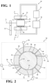
- FIGs 1-2 illustrate a lubricant supported electric motor 10 in accordance with an aspect of the invention.
- the lubricant supported electric motor 10 includes a stator 12 and a rotor 14 extending along an axis A and movably (i.e., rotatably) disposed within the stator 12 to define a gap 16 (also shown as "G" in Figure 1 ) therebetween.
- the stator 12 and the rotor 14 can be reversed, with the stator 12 extending along the axis A and the rotor 14 rotatably disposed around the stator 12.
- a lubricant 18 is disposed in the gap 16 for supporting the rotor 14 within the stator 12, and providing continuous contact between these components.
- the lubricant 18 may therefore act as a buffer (e.g., suspension) between the stator 12 and the rotor 14 minimizing or preventing contact therebetween.
- the lubricant 18 prevents direct contact between the stator 12 and rotor 14 and provides an electric lubricant supported motor 10 which is robust to shock and vibration loading due to the presence of the lubricant 18.
- a substantially incompressible lubricant 18 may be used in order to minimize the gap between the stator 12 and rotor 14.
- the stator 12 defines a passageway 20 disposed in fluid communication with the gap 16 for introducing the lubricant 18.
- the passageway 20 could be provided on any other components of the lubricant supported electric motor 10 without departing from the subject invention as defined in the appended claims.
- the lubricant 18 may be cycled or pumped through the passageway 20 and into the gap 16 in various ways.
- a high pressure source e.g., a pump
- a low pressure source e.g., a sump
- Rotation of the rotor 14 relative to the stator 12 may operate as a self-pump to drive lubricant 18 through the passageway 20 and into the gap 16.
- the rotor 14 is interconnected to a drive assembly 22 for coupling the lubricant supported electric motor 10 to one of the plurality of wheels of a vehicle.
- the drive assembly 22 may include a planetary gear system.
- the drive assembly 22 may include one or more parallel axis gears.
- the stator 12 and rotor 14 are configured to exert an electromagnetic force therebetween to convert electrical energy into mechanical energy, moving the rotor 14 and ultimately driving the wheel coupled to the lubricant supported electric motor 10 via the drive assembly 22.
- the drive assemblies 20 may provide one or more reduction ratios between the lubricant supported electric motor 10 and the wheel in response to movement of the rotor 14.
- the rotor 14 presents an inner raceway 28 and the stator 12 presents an outer raceway 30.
- the inner and outer raceways 28, 30 collectively define at least one hydrostatic support chamber 32 which is established by a portion of the gap 16 and receives the lubricant 18 for supporting the rotor 14 within the stator 12.
- the hydrostatic support chamber 32 which is established in the gap 16 between the inner and outer raceways 28, 30 determines a dynamic pressure developed when the lubricant supported electric motor 10 is in hydrodynamic mode.
- the gap 16 between the inner and outer raceways 28, 30 also determines the pressure in the hydrostatic support chamber 32 when the lubricant supported electric motor 10 is in hydrostatic mode.
- the at least one hydrostatic support chamber 32 includes a plurality of hydrostatic support chambers 32 spaced circumferentially around and between the stator 12 and the rotor 14 and which each have their individualized pressure in the hydrodynamic and hydrostatic modes.
- the at least one hydrostatic support chamber 32 can include four hydrostatic support chambers 32 circumferentially spaced from one another around the axis A.
- any number of hydrostatic support chambers 32 can be utilized without departing from the scope of the invention as defined in the appended claims.
- the stator 12 defines a plurality of passageways 20 each disposed in fluid communication with a respective one of the hydrostatic support chambers 32 for supplying lubricant thereto.
- the lubricant supported electric motor 10 includes a monitoring port 34 disposed in fluid communication with each hydrostatic support chamber 32.
- a sensor 36 is coupled to the monitoring port 34 for sensing the operating characteristic of the lubricant 18 disposed within the at least one hydrostatic support chamber 28.
- the sensor 36 can be a pressure sensor configured to sense a pressure of the lubricant 18 disposed within the at least one hydrostatic support chamber 28.
- the sensor 36 could also be comprised of other sensors 36, such as a temperature sensor for sensing a temperature of the lubricant 18 or a viscosity sensor for sensing a viscosity of the lubricant, without departing from the scope of the invention as defined in the appended claims.
- each hydrostatic support chamber 32 includes its own respective monitoring port 34 and sensor 36 for providing individualized monitoring of the plurality of hydrostatic support chambers 32.
- the utilization of the monitoring port 34 and the sensor 36 advantageously improves the performance of the lubricant supported electric motor 10 by providing the ability to detect operating characteristics of the lubricant 18 disposed within each of the hydrostatic support chambers 28, which is used and analyzed to detect certain operating characteristics of the lubricant supported electric motor 10 such as oil supply faults, stable or instable motor operation, as well as others.
- the monitoring port 34 and the sensor 36 facilitates real-time diagnostics and prognostics for the lubricant supported electric motor 10.
- each sensor 36 is preferably electrically connected to a controller 38 for sending the monitored operating characteristic of the lubricant 18 and/or hydrostatic support chamber 32 to the controller 38 for further evaluation to determine the operating characteristic of the lubricant supported electric motor 10 and provide the real-time diagnostics and prognostics.
- the operating characteristics e.g., pressure, temperature, viscosity
- the controller 38 can be used by the controller 38 to:
- monitoring port 34 and sensor 36 advantageously provides for optimized performance and operating characteristics for the lubricant supported electric motor 10 in real-time.
- the monitoring port 34 and sensor 36 allows for the monitoring and diagnosing of the motor's performance in real-time using, for example, pressure measurements of the lubricant 18 in the hydrostatic support chamber 32. This improved monitoring of the motor's performance ultimately leads to better overall performance of the lubricant supported electric motor 10 compared to its static and very conservatively designed counterparts.
Landscapes
- Engineering & Computer Science (AREA)
- General Engineering & Computer Science (AREA)
- Mechanical Engineering (AREA)
- Power Engineering (AREA)
- Chemical & Material Sciences (AREA)
- Combustion & Propulsion (AREA)
- Transportation (AREA)
- Microelectronics & Electronic Packaging (AREA)
- Connection Of Motors, Electrical Generators, Mechanical Devices, And The Like (AREA)
- Rolling Contact Bearings (AREA)
- Motor Or Generator Frames (AREA)
Claims (10)
- Schmiermittelgelagerter Elektromotor (10), der Folgendes aufweist:einen Stator (12), der eine äußere Laufbahn (30) aufweist;einen Rotor (14), der sich entlang einer Achse (A) erstreckt und drehbar in dem Stator (12) angeordnet ist;wobei der Rotor (14) eine innere Laufbahn (28) aufweist, die in einem Abstand zu der äußeren Laufbahn (30) angeordnet ist, um dazwischen wenigstens eine hydrostatische Stützkammer (32) zu definieren;ein Schmiermittel (18), das in der hydrostatischen Stützkammer (32) angeordnet ist, um den Rotor (14) in dem Stator (12) abstützen bzw. zu lagern,gekennzeichnet durch:einen Überwachungsanschluss (34), der in Fluidverbindung mit der wenigstens einen hydrostatischen Stützkammer (32) angeordnet ist; undeinen Sensor (36), der mit dem Überwachungsanschluss (34) gekoppelt ist, um eine Betriebseigenschaft des in der wenigstens einen hydrostatischen Stützkammer (32) angeordneten Schmiermittels (18) zu überwachen, um einen Echtzeit-Betriebszustand des schmiermittelgelagerten Elektromotors (10) zu bestimmen.
- Schmiermittelgelagerter Elektromotor (10) nach Anspruch 1, der des Weiteren eine Steuereinrichtung (38) aufweist, die in elektrischer Verbindung mit dem Sensor (36) angeordnet und dafür vorgesehen ist, die überwachte Betriebseigenschaft des in der hydrostatischen Stützkammer (32) angeordneten Schmiermittels (18) zu analysieren und den Echtzeit-Betriebszustand des schmiermittelgelagerten Elektromotors (10) zu bestimmen.
- Schmiermittelgelagerter Elektromotor (10) nach Anspruch 1, wobei der Sensor (36) als Drucksensor ausgebildet ist, der dafür vorgesehen ist, den Druck des in der wenigstens einen hydrostatischen Stützkammer (32) angeordneten Schmiermittels (18) zu messen.
- Schmiermittelgelagerter Elektromotor (10) nach Anspruch 1, wobei der Sensor (36) als Temperatursensor ausgebildet ist, der dafür vorgesehen ist, eine Temperatur des in der wenigstens einen hydrostatischen Stützkammer (32) angeordneten Schmiermittels (18) zu messen.
- Schmiermittelgelagerter Elektromotor (10) nach Anspruch 2, wobei die wenigstens eine hydrostatische Stützkammer (32) mehrere hydrostatische Stützkammern (32) aufweist, die in Umfangsrichtung um die Achse (A) herum in einem Abstand voneinander angeordnet sind.
- Schmiermittelgelagerter Elektromotor (10) nach Anspruch 5, der des Weiteren mehrere Überwachungsanschlüsse (34), die jeweils in Fluidverbindung mit einer jeweiligen der hydrostatischen Stützkammern (32) angeordnet sind, und eine Vielzahl von Sensoren (36) aufweist, die jeweils in Verbindung mit einem jeweiligen der Überwachungsanschlüsse (34) angeordnet sind.
- Schmiermittelgelagerter Elektromotor (10) nach Anspruch 6, wobei die Steuereinrichtung (38) in elektrischer Verbindung mit jedem der mehreren Sensoren (36) angeordnet und dafür vorgesehen ist, Betriebseigenschaften des in jeder der mehreren hydrostatischen Stützkammern (32) angeordneten Schmiermittels (18) zu empfangen und zu analysieren.
- Schmiermittelgelagerter Elektromotor (10) nach Anspruch 1, wobei der Rotor (14) mit einer Achsantriebsvorrichtung (22) verbunden ist, die mit einem Rad eines Fahrzeugs verbunden ist.
- Schmiermittelgelagerter Elektromotor (10) nach Anspruch 1, wobei der Stator (12) einen Durchgang (20) festlegt, der in Fluidverbindung mit der wenigstens einen hydrostatischen Stützkammer (32) steht, um das Schmiermittel (18) zuzuführen.
- Schmiermittelgelagerter Elektromotor (10) nach Anspruch 5, wobei der Stator (12) mehrere Durchgänge (20) festlegt, die jeweils in Fluidverbindung mit einer entsprechenden der mehreren hydrostatischen Stützkammern (32) stehen, um das Schmiermittel (18) zuzuführen.
Applications Claiming Priority (3)
| Application Number | Priority Date | Filing Date | Title |
|---|---|---|---|
| US201962912122P | 2019-10-08 | 2019-10-08 | |
| US17/064,684 US11863053B2 (en) | 2019-10-08 | 2020-10-07 | Lubricant supported electric motor with a monitoring port |
| PCT/US2020/054671 WO2021072007A1 (en) | 2019-10-08 | 2020-10-08 | Lubricant supported electric motor with a monitoring port |
Publications (3)
| Publication Number | Publication Date |
|---|---|
| EP4021752A1 EP4021752A1 (de) | 2022-07-06 |
| EP4021752B1 true EP4021752B1 (de) | 2025-02-19 |
| EP4021752C0 EP4021752C0 (de) | 2025-02-19 |
Family
ID=75274426
Family Applications (1)
| Application Number | Title | Priority Date | Filing Date |
|---|---|---|---|
| EP20797934.5A Active EP4021752B1 (de) | 2019-10-08 | 2020-10-08 | Schmierstoffgestützter elektromotor mit einem überwachungsanschluss |
Country Status (5)
| Country | Link |
|---|---|
| US (1) | US11863053B2 (de) |
| EP (1) | EP4021752B1 (de) |
| CN (1) | CN114600349A (de) |
| PL (1) | PL4021752T3 (de) |
| WO (1) | WO2021072007A1 (de) |
Families Citing this family (1)
| Publication number | Priority date | Publication date | Assignee | Title |
|---|---|---|---|---|
| CN115628849A (zh) * | 2022-10-13 | 2023-01-20 | 中国第一汽车股份有限公司 | 一种新能源汽车高速转子去应力装置及方法 |
Family Cites Families (13)
| Publication number | Priority date | Publication date | Assignee | Title |
|---|---|---|---|---|
| US3101224A (en) * | 1960-09-12 | 1963-08-20 | Boeing Co | High load hydrostatic bearing |
| US3119639A (en) * | 1962-01-09 | 1964-01-28 | Boeing Co | Hydrostatic bearing |
| US3546505A (en) * | 1968-05-06 | 1970-12-08 | Rex Chainbelt Inc | Vibrator motor with self-container lubricant circulator |
| JPS566919A (en) * | 1979-06-26 | 1981-01-24 | Canon Inc | Fluid bearing |
| JPS569668A (en) * | 1979-07-02 | 1981-01-31 | Haruhisa Tezuka | Generating device utilizing wave power |
| JPH0755440B2 (ja) * | 1992-03-05 | 1995-06-14 | 工業技術院長 | 精密加工機用静圧主軸の熱変位履歴改善方法 |
| US6324899B1 (en) * | 1998-04-02 | 2001-12-04 | Reliance Electric Technologies, Llc | Bearing-sensor integration for a lubrication analysis system |
| JP3569668B2 (ja) * | 2000-09-11 | 2004-09-22 | Thk株式会社 | 空気動圧スピンドル装置 |
| JP4134541B2 (ja) * | 2000-09-25 | 2008-08-20 | 株式会社ジェイテクト | 流体軸受 |
| DE102007022221A1 (de) | 2007-05-11 | 2008-11-13 | Robert Bosch Gmbh | Hydrodynamische Kraftstoffhochdruckpumpe |
| EP2108832B1 (de) | 2008-04-10 | 2015-12-02 | Siemens Aktiengesellschaft | Generator und Windturbine |
| CN103089810B (zh) | 2013-01-25 | 2015-04-29 | 西安交通大学 | 一种在线振动控制的可倾瓦径向滑动轴承装置 |
| WO2019067691A1 (en) | 2017-09-27 | 2019-04-04 | Neapco Intellectual Property Holdings, Llc | LUBRICANT-SUPPORTED ELECTRIC MOTOR |
-
2020
- 2020-10-07 US US17/064,684 patent/US11863053B2/en active Active
- 2020-10-08 CN CN202080070106.2A patent/CN114600349A/zh active Pending
- 2020-10-08 EP EP20797934.5A patent/EP4021752B1/de active Active
- 2020-10-08 PL PL20797934.5T patent/PL4021752T3/pl unknown
- 2020-10-08 WO PCT/US2020/054671 patent/WO2021072007A1/en not_active Ceased
Also Published As
| Publication number | Publication date |
|---|---|
| PL4021752T3 (pl) | 2025-05-05 |
| WO2021072007A1 (en) | 2021-04-15 |
| US11863053B2 (en) | 2024-01-02 |
| US20210104936A1 (en) | 2021-04-08 |
| CN114600349A (zh) | 2022-06-07 |
| EP4021752C0 (de) | 2025-02-19 |
| EP4021752A1 (de) | 2022-07-06 |
Similar Documents
| Publication | Publication Date | Title |
|---|---|---|
| US11355996B2 (en) | Lubricant supported electric motor with controlled and balanced lubricant flow | |
| EP4014304A1 (de) | Schmiermittelversorgungssystem und verfahren für einen mit schmiermittelunterstützten elektromotor | |
| EP2770229A1 (de) | Achsanordnung und Verfahren zur Kontrolle der Schmierung | |
| KR19980081087A (ko) | 멀티플 챔버를 갖는 트윈 클러치 액슬 | |
| KR101724508B1 (ko) | 하이브리드 차량의 림프 홈 주행 방법 | |
| US11418086B2 (en) | Axle assembly having an electric motor module and a terminal box | |
| CN202189050U (zh) | 滚动轴承润滑模拟实验装置 | |
| WO2015027036A1 (en) | Optimized outer clutch housing for reduced spin loss, improved oil flow and improved clutch durability | |
| US20230001738A1 (en) | Lubricant supported electric motor with wheel support | |
| EP4021752B1 (de) | Schmierstoffgestützter elektromotor mit einem überwachungsanschluss | |
| US20240429777A1 (en) | Lubricant supported electric motor with bearing support | |
| CN115808308B (zh) | 一种滚轮轴承与导轮涂层性能试验装置 | |
| CN109114103A (zh) | 智能动压轴承 | |
| US10935089B2 (en) | Method of determining and predicting a ball loss in a ball and ramp assembly | |
| US11563359B2 (en) | Lubricant supported electric motor with a movable raceway and an optimized method of operating same | |
| CN108167072A (zh) | 冷链车用发电机组 | |
| CN213360893U (zh) | 一种离合装置 | |
| US20210091628A1 (en) | Lubricant supported electric motor with a profiled raceway | |
| CN118728938A (zh) | 用于工业车辆的动力传动系统总成 |
Legal Events
| Date | Code | Title | Description |
|---|---|---|---|
| STAA | Information on the status of an ep patent application or granted ep patent |
Free format text: STATUS: UNKNOWN |
|
| STAA | Information on the status of an ep patent application or granted ep patent |
Free format text: STATUS: THE INTERNATIONAL PUBLICATION HAS BEEN MADE |
|
| PUAI | Public reference made under article 153(3) epc to a published international application that has entered the european phase |
Free format text: ORIGINAL CODE: 0009012 |
|
| STAA | Information on the status of an ep patent application or granted ep patent |
Free format text: STATUS: REQUEST FOR EXAMINATION WAS MADE |
|
| 17P | Request for examination filed |
Effective date: 20220330 |
|
| AK | Designated contracting states |
Kind code of ref document: A1 Designated state(s): AL AT BE BG CH CY CZ DE DK EE ES FI FR GB GR HR HU IE IS IT LI LT LU LV MC MK MT NL NO PL PT RO RS SE SI SK SM TR |
|
| DAV | Request for validation of the european patent (deleted) | ||
| DAX | Request for extension of the european patent (deleted) | ||
| GRAP | Despatch of communication of intention to grant a patent |
Free format text: ORIGINAL CODE: EPIDOSNIGR1 |
|
| STAA | Information on the status of an ep patent application or granted ep patent |
Free format text: STATUS: GRANT OF PATENT IS INTENDED |
|
| INTG | Intention to grant announced |
Effective date: 20240920 |
|
| GRAS | Grant fee paid |
Free format text: ORIGINAL CODE: EPIDOSNIGR3 |
|
| GRAA | (expected) grant |
Free format text: ORIGINAL CODE: 0009210 |
|
| STAA | Information on the status of an ep patent application or granted ep patent |
Free format text: STATUS: THE PATENT HAS BEEN GRANTED |
|
| AK | Designated contracting states |
Kind code of ref document: B1 Designated state(s): AL AT BE BG CH CY CZ DE DK EE ES FI FR GB GR HR HU IE IS IT LI LT LU LV MC MK MT NL NO PL PT RO RS SE SI SK SM TR |
|
| REG | Reference to a national code |
Ref country code: GB Ref legal event code: FG4D |
|
| REG | Reference to a national code |
Ref country code: CH Ref legal event code: EP |
|
| REG | Reference to a national code |
Ref country code: DE Ref legal event code: R096 Ref document number: 602020046401 Country of ref document: DE |
|
| REG | Reference to a national code |
Ref country code: IE Ref legal event code: FG4D |
|
| U01 | Request for unitary effect filed |
Effective date: 20250219 |
|
| U07 | Unitary effect registered |
Designated state(s): AT BE BG DE DK EE FI FR IT LT LU LV MT NL PT RO SE SI Effective date: 20250225 |
|
| PG25 | Lapsed in a contracting state [announced via postgrant information from national office to epo] |
Ref country code: RS Free format text: LAPSE BECAUSE OF FAILURE TO SUBMIT A TRANSLATION OF THE DESCRIPTION OR TO PAY THE FEE WITHIN THE PRESCRIBED TIME-LIMIT Effective date: 20250519 |
|
| PG25 | Lapsed in a contracting state [announced via postgrant information from national office to epo] |
Ref country code: ES Free format text: LAPSE BECAUSE OF FAILURE TO SUBMIT A TRANSLATION OF THE DESCRIPTION OR TO PAY THE FEE WITHIN THE PRESCRIBED TIME-LIMIT Effective date: 20250219 |
|
| PG25 | Lapsed in a contracting state [announced via postgrant information from national office to epo] |
Ref country code: NO Free format text: LAPSE BECAUSE OF FAILURE TO SUBMIT A TRANSLATION OF THE DESCRIPTION OR TO PAY THE FEE WITHIN THE PRESCRIBED TIME-LIMIT Effective date: 20250519 Ref country code: IS Free format text: LAPSE BECAUSE OF FAILURE TO SUBMIT A TRANSLATION OF THE DESCRIPTION OR TO PAY THE FEE WITHIN THE PRESCRIBED TIME-LIMIT Effective date: 20250619 |
|
| PG25 | Lapsed in a contracting state [announced via postgrant information from national office to epo] |
Ref country code: HR Free format text: LAPSE BECAUSE OF FAILURE TO SUBMIT A TRANSLATION OF THE DESCRIPTION OR TO PAY THE FEE WITHIN THE PRESCRIBED TIME-LIMIT Effective date: 20250219 |
|
| PG25 | Lapsed in a contracting state [announced via postgrant information from national office to epo] |
Ref country code: GR Free format text: LAPSE BECAUSE OF FAILURE TO SUBMIT A TRANSLATION OF THE DESCRIPTION OR TO PAY THE FEE WITHIN THE PRESCRIBED TIME-LIMIT Effective date: 20250520 |
|
| PG25 | Lapsed in a contracting state [announced via postgrant information from national office to epo] |
Ref country code: SM Free format text: LAPSE BECAUSE OF FAILURE TO SUBMIT A TRANSLATION OF THE DESCRIPTION OR TO PAY THE FEE WITHIN THE PRESCRIBED TIME-LIMIT Effective date: 20250219 |
|
| PG25 | Lapsed in a contracting state [announced via postgrant information from national office to epo] |
Ref country code: CZ Free format text: LAPSE BECAUSE OF FAILURE TO SUBMIT A TRANSLATION OF THE DESCRIPTION OR TO PAY THE FEE WITHIN THE PRESCRIBED TIME-LIMIT Effective date: 20250219 |
|
| PG25 | Lapsed in a contracting state [announced via postgrant information from national office to epo] |
Ref country code: SK Free format text: LAPSE BECAUSE OF FAILURE TO SUBMIT A TRANSLATION OF THE DESCRIPTION OR TO PAY THE FEE WITHIN THE PRESCRIBED TIME-LIMIT Effective date: 20250219 |