EP4021359B1 - Verstellvorrichtung für eine mandibuläre vorschubvorrichtung - Google Patents
Verstellvorrichtung für eine mandibuläre vorschubvorrichtung Download PDFInfo
- Publication number
- EP4021359B1 EP4021359B1 EP20859037.2A EP20859037A EP4021359B1 EP 4021359 B1 EP4021359 B1 EP 4021359B1 EP 20859037 A EP20859037 A EP 20859037A EP 4021359 B1 EP4021359 B1 EP 4021359B1
- Authority
- EP
- European Patent Office
- Prior art keywords
- extraoral
- adjustment wheel
- lower arm
- body portion
- adjustment
- Prior art date
- Legal status (The legal status is an assumption and is not a legal conclusion. Google has not performed a legal analysis and makes no representation as to the accuracy of the status listed.)
- Active
Links
Images


Classifications
-
- A—HUMAN NECESSITIES
- A61—MEDICAL OR VETERINARY SCIENCE; HYGIENE
- A61F—FILTERS IMPLANTABLE INTO BLOOD VESSELS; PROSTHESES; DEVICES PROVIDING PATENCY TO, OR PREVENTING COLLAPSING OF, TUBULAR STRUCTURES OF THE BODY, e.g. STENTS; ORTHOPAEDIC, NURSING OR CONTRACEPTIVE DEVICES; FOMENTATION; TREATMENT OR PROTECTION OF EYES OR EARS; BANDAGES, DRESSINGS OR ABSORBENT PADS; FIRST-AID KITS
- A61F5/00—Orthopaedic methods or devices for non-surgical treatment of bones or joints; Nursing devices ; Anti-rape devices
- A61F5/56—Devices for preventing snoring
- A61F5/566—Intra-oral devices
-
- A—HUMAN NECESSITIES
- A61—MEDICAL OR VETERINARY SCIENCE; HYGIENE
- A61C—DENTISTRY; APPARATUS OR METHODS FOR ORAL OR DENTAL HYGIENE
- A61C7/00—Orthodontics, i.e. obtaining or maintaining the desired position of teeth, e.g. by straightening, evening, regulating, separating, or by correcting malocclusions
- A61C7/06—Extra-oral force transmitting means, i.e. means worn externally of the mouth and placing a member in the mouth under tension
-
- A—HUMAN NECESSITIES
- A61—MEDICAL OR VETERINARY SCIENCE; HYGIENE
- A61F—FILTERS IMPLANTABLE INTO BLOOD VESSELS; PROSTHESES; DEVICES PROVIDING PATENCY TO, OR PREVENTING COLLAPSING OF, TUBULAR STRUCTURES OF THE BODY, e.g. STENTS; ORTHOPAEDIC, NURSING OR CONTRACEPTIVE DEVICES; FOMENTATION; TREATMENT OR PROTECTION OF EYES OR EARS; BANDAGES, DRESSINGS OR ABSORBENT PADS; FIRST-AID KITS
- A61F5/00—Orthopaedic methods or devices for non-surgical treatment of bones or joints; Nursing devices ; Anti-rape devices
- A61F5/56—Devices for preventing snoring
Definitions
- This invention relates to mandibular advancement devices, particularly to devices worn by a person to prevent obstructive sleep apnoea, and in particular to adjustment means for the extraoral portion of that device.
- a mandibular advancement device of the type referred to in this specification is already disclosed in WO 2019/071291 A1 and WO 2006/072147 .
- the mandibular advancement device disclosed has both intraoral and extraoral portions.
- the present invention is mainly concerned with the extraoral portion of the device.
- the extraoral portion of the device is substantially J-Curved and initially extends directly away from the face of the wearer, then curves back towards the face.
- the posterior end of the J curve includes an upper pad that contacts the subnasal maxillary bone.
- the parts of the intraoral portion that make contact with the mandible are braced against the contact of the upper pad. By increasing or decreasing the pressure on the upper pad, the position of the mandible is changed.
- WO 2019/071291 discloses a method of monitoring the status of a body of a person during sleep, said method comprising: - retaining in or adjacent the mouth or nose of said person an electronic detector which detects indications of the state of said body, - wirelessly transmitting a first data stream representing said indications to a data receiving means, - transmitting said first data stream from said data receiving means to a data processing means, - processing said first data stream within said data processing means to produce a second data stream representing said indications, or conclusion drawn from said indications, and - displaying a visual representation of said indications or conclusions.
- WO 2019/094744 discloses a provisional oral appliance for the temporary treatment of sleep apnea includes a pair of trays for receiving the user's upper and lower teeth, and a pair of adjustable, fixed-length strut assemblies pivotably connected to the upper tray and lower tray.
- US 2014/224257 discloses a device adapted to limit relative positioning of a mandible and a maxilla of a user includes a housing and a telescoping member movable within the housing to change a length of the device.
- US 2011/217674 discloses a mandibular manipulator instrument as a standalone tool or with associated mouthpiece that includes two interlocking laterally sliding frames comprising a movable upper and a lower incisor pull, shaped for receiving a patient's central incisor teeth and a pair of pinion shafts for driving the upper and lower incisor pulls.
- US 2007/209666 discloses a pharyngeal airway adjuster, or mandible positioning device, has a maxillary dentition engagement component and a mandibular dentition engagement component, each on opposite sides of a plane extending therebetween.
- the present invention is an adjustment means for a mandibular advancement device.
- the mandibular advancement device being of the type having both intraoral and extraoral portions, including a body portion that is at the interface between the intraoral and extraoral portions and thereby is part intraoral and part extraoral.
- the extraoral portion includes a lower arm that is substantially straight and extends directly outwardly from the extraoral part of the body portion, and a curved upper arm that curves upwardly from the lower arm and back towards the face of a person using the device.
- the posterior end of the upper arm includes a pad assembly that is adapted to make contact with and apply pressure to the subnasal maxillary bone of the wearer.
- a substantial portion of the lower arm includes a thread that is adapted to be threaded into an adjustment wheel that is housed within the extraoral part of the body portion so that turning the adjustment wheel in one direction causes the extraoral portion to retract into the body portion, and thereby cause the upper pad to apply greater pressure to the subnasal maxillary bone, and turning the adjustment wheel in the opposite direction causes the extraoral portion to extend out from the extraoral part of the body portion, thereby causing the upper pad to apply decreased pressure to the subnasal maxillary bone.
- the threaded portions in both the lower arm and the adjustment wheel are arranged so that one complete revolution of the adjustment wheel causes the extraoral portion to extend or retract by one millimetre in length, and the changes in pressure on the subnasal maxillary bone combine with the intraoral portion of the device to adjust the position of the mandibular of the wearer of the device.
- the device includes haptic feedback at regular distance increments to a person manipulating the adjustment wheel.
- the haptic feedback is felt upon each complete revolution of the adjustment wheel, either clockwise or counter-clockwise.
- the device includes an audible click noise that is heard at regular distance increments by a person manipulating the adjustment wheel.
- the audible click noise is heard at each complete revolution of the adjustment wheel, either clockwise or counter-clockwise.
- the adjustment wheel includes means that are adapted to engage with corresponding means on the body portion so that as the adjustment wheel makes any complete 360° revolution, the corresponding pair of at least one small lateral projections interfere with each other thereby creating a haptic sensation and/or an audible click.
- the adjustment wheel includes a small groove that is adapted to engage with a corresponding small lateral projection on the body portion so that as the adjustment wheel makes any complete 360° revolution, the small lateral projection is adapted to interfere with the groove thereby creating a haptic feedback and/or an audible click.
- the adjustment wheel includes at least one small lateral projection that is adapted to impinge upon a corresponding at least one small lateral projection on the body portion so that as the adjustment wheel makes any complete 360° revolution, the corresponding pair of at least one small lateral projections interfere with each other thereby creating a haptic feedback and/or an audible click.
- a substantial portion of the lower arm includes measurement graduations that enable a person to have visual means to initially adjust to position of the extraoral portion prior to having the device used by using the adjustment wheel.
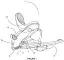
- FIG. 1 where we are shown the mandibular advancement device 1.
- the extraoral portion 3 the intraoral portion 5 and the body portion 7 that is intraoral in the posterior part and extraoral in the anterior part.
- the lower arm 9 is substantially straight and emerges directly forward out of the body portion 7.
- the lower arm 9 includes a thread 11 that extends substantially along its length.
- the extraoral portion 3 also includes a curved upper arm 13 that curves upwardly from the anterior end of the lower arm, and back towards the face of the wearer.
- pad assembly 15 At the posterior end of the upper arm 13 there is pad assembly 15 that is adapted to make contact with, and apply pressure to, the subnasal maxillary bone of the wearer.
- the posterior portion of the lower arm 9 is adapted to slide inside an anterior cavity 17 in the body portion 7.
- the body portion 7 includes an adjustment wheel 19 that has an aperture that is adapted to receive the lower arm 9 within.
- the aperture is internally threaded.
- the internal thread of the adjustment wheel 19 is adapted to engage with the externally threaded portion of the lower arm.
- the threads are arranged so that one full 360° turn of the adjustment wheel causes the lower arm to move a distance of one millimetre. Rotation of the adjustment wheel 19 in one direction causes the lower arm 9 to retract into the body portion 7, and rotation of the adjustment wheel 19 in the opposite direction causes the lower arm 9 to extend further out from the body portion.
- FIG. 2a a side view of the mandibular advancement device 1.
- Figure 2 shows the device 1 in use.
- the pad assembly 15 is arranged to make contact with the subnasal maxillary bone.
- Rotational adjustment of the adjustment wheel 19 causes the pad assembly 15 to exert more or less pressure on the subnasal maxillary bone, and this combines with the intraoral portion of the device 1 to enable manual adjustment of the position of the mandibular.
- the lower arm 9 includes graduated distance indicators 21. These assist a person setting up a device for first use. The user can adjust the lower arm into a general position by using the adjustment wheel 19 to move the lower arm 9 into a rough first position, by using the graduated distance indicators 11 as a guide, and then when the device is inserted into the wearer's mouth, fine adjustments of the lower arm's position can be made in order to maximise the effect of the device and the wearer's comfort.
- the adjustment wheel 19 has an internal thread 23 that engages with the external thread on the lower arm 9.
- the wheel has at least one groove 25, but in this example, two diametrically opposed grooves 25 and 25' respectively are shown.
- the body portion 7 is made up of both a top and bottom plate. In this illustration, only the bottom plate 27 is shown. In this view, it is easy to see the cavity 17 formed into the anterior end of the body portion 7 of the device.
- the anterior portion of the lower arm 9 is adapted to be insertable into the cavity 17 and into the adjustment wheel 19.
- the external thread 11 of the lower arm 9 is adapted to engage with the internal thread 23 of the adjustment wheel 19.
- the engagement of the small projection 29 and 29' also causes an audible click.
- the interengagement of the threads as the adjustment wheel 19 is turned is arranged so that one full rotation of the wheel 19 causes the lower arm 9 to move a distance of 1 millimetre.
- the haptic and audible feedback will occur on every half full turn of the wheel 19.
Landscapes
- Health & Medical Sciences (AREA)
- Veterinary Medicine (AREA)
- General Health & Medical Sciences (AREA)
- Public Health (AREA)
- Life Sciences & Earth Sciences (AREA)
- Animal Behavior & Ethology (AREA)
- Pulmonology (AREA)
- Nursing (AREA)
- Otolaryngology (AREA)
- Orthopedic Medicine & Surgery (AREA)
- Engineering & Computer Science (AREA)
- Biomedical Technology (AREA)
- Heart & Thoracic Surgery (AREA)
- Vascular Medicine (AREA)
- Epidemiology (AREA)
- Oral & Maxillofacial Surgery (AREA)
- Dentistry (AREA)
- Orthopedics, Nursing, And Contraception (AREA)
Claims (4)
- Vorrichtung zum Vorschieben des Unterkiefers (1), die sowohl intraorale (5) als auch extraorale (3) Abschnitte aufweist, wobei der extraorale Abschnitt einen unteren Arm (9), der im Wesentlichen gerade ist, und einen gekrümmten oberen Arm (13) der sich vom unteren Arm nach oben und zurück in Richtung eines Gesichts eines Trägers der Vorrichtung krümmt, aufweist, und wobei ein hinteres Ende des oberen Arms eine Polsterbaugruppe aufweist, die angepasst ist, mit einem subnasalen Oberkieferknochen des Trägers in Kontakt zu treten und Druck auf diesen auszuüben, wobei die Vorrichtung zum Vorschieben des Unterkiefers auch ein Einstellmittel (19) aufweist, einschließlich:einen Körperabschnitt (7), der sich an einer Schnittstelle zwischen dem intraoralen und dem extraoralen Abschnitt befindet und dadurch teilweise intraoral und teilweise extraoral ist, wobei der Körperabschnitt ein Einstellrad mit einem Gewinde (11) aufweist, wobei das Einstellrad im extraoralen Teil des Körperabschnitts untergebracht ist,wobei:der untere Arm des extraoralen Abschnitts sich direkt vom extraoralen Teil des Körperabschnitts nach außen erstreckt,ein wesentlicher Abschnitt des unteren Arms ein Gewinde einschließt, das angepasst ist, in das Einstellrad eingeschraubt zu werden, sodass ein Drehen des Einstellrads in eine Richtung bewirkt, dass sich der extraorale Abschnitt in den Körperabschnitt zurückzieht, wodurch das obere Polster einen größeren Druck auf den subnasalen Oberkieferknochen ausübt, und ein Drehen des Einstellrads in die entgegengesetzte Richtung bewirkt, dass sich der extraorale Abschnitt aus dem extraoralen Teil des Körperabschnitts heraus erstreckt, wodurch das obere Polster einen geringeren Druck auf den subnasalen Oberkieferknochen ausübt,dadurch gekennzeichnet, dassdie Gewinde sowohl des unteren Arms als auch des Einstellrads so angeordnet sind, dass eine vollständige Umdrehung des Einstellrads in einer ersten Richtung bewirkt, dass der extraorale Abschnitt um einen Millimeter verlängert wird, und eine vollständige Umdrehung des Einstellrads in der entgegengesetzten Richtung bewirkt, dass der extraorale Abschnitt um einen Millimeter zurückgezogen wird, und die Änderungen des Drucks auf den subnasalen Oberkieferknochen, die durch die Verlängerung oder das Zurückziehen des extraoralen Abschnitts verursacht werden, mit dem intraoralen Abschnitt der Vorrichtung kombiniert werden, um die Position eines Unterkiefers des Trägers der Vorrichtung einzustellen, die Vorrichtung eine haptische Rückmeldung (25, 29) einschließt, die bei jeder vollständigen Umdrehung des Einstellrads, entweder im oder gegen den Uhrzeigersinn, spürbar ist, wobei das Einstellrad eine Nut (25) einschließt, die geeignet ist, mit einem entsprechenden seitlichen Vorsprung (29) auf dem Körperabschnitt in Eingriff zu kommen, sodass, wenn das Einstellrad eine vollständige 360°-Umdrehung macht, der seitliche Vorsprung so angepasst ist, dass er in die Nut eingreift, wodurch eine haptische Rückmeldung und/oder ein hörbares Klicken erzeugt wird, undein wesentlicher Abschnitt des unteren Arms der Vorrichtung Messeinteilungen (21) aufweist die es der Person ermöglichen, die Position des extraoralen Abschnitts zunächst visuell einzustellen, sodass eine Anfangsposition des unteren Arms voreingestellt werden kann.
- Einstellmittel nach Anspruch 1, wobei die Vorrichtung ein hörbares Klickgeräusch einschließt, das von der Person, die das Einstellrad bedient, in regelmäßigen Abständen gehört wird.
- Einstellmittel nach Anspruch 2, wobei das hörbare Klickgeräusch bei jeder vollständigen Umdrehung des Einstellrads, entweder im oder gegen den Uhrzeigersinn, zu hören ist.
- Einstellmittel nach Anspruch 3, wobei das Einstellrad mindestens einen kleinen seitlichen Vorsprung einschließt, der angepasst ist, mit einem entsprechenden kleinen seitlichen Vorsprung auf dem Körperabschnitt physisch in Eingriff zu kommen, sodass, wenn das Einstellrad eine vollständige 360°-Drehung macht, die entsprechenden seitlichen Vorsprünge miteinander interferieren und dadurch eine haptische Rückmeldung und/oder ein hörbares Klicken erzeugen.
Applications Claiming Priority (2)
| Application Number | Priority Date | Filing Date | Title |
|---|---|---|---|
| AU2019903107A AU2019903107A0 (en) | 2019-08-26 | Adjustment Means | |
| PCT/AU2020/000088 WO2021035278A1 (en) | 2019-08-26 | 2020-08-26 | Adjustment means for a mandibular advancement device |
Publications (4)
| Publication Number | Publication Date |
|---|---|
| EP4021359A1 EP4021359A1 (de) | 2022-07-06 |
| EP4021359A4 EP4021359A4 (de) | 2023-05-03 |
| EP4021359C0 EP4021359C0 (de) | 2024-09-25 |
| EP4021359B1 true EP4021359B1 (de) | 2024-09-25 |
Family
ID=74683253
Family Applications (1)
| Application Number | Title | Priority Date | Filing Date |
|---|---|---|---|
| EP20859037.2A Active EP4021359B1 (de) | 2019-08-26 | 2020-08-26 | Verstellvorrichtung für eine mandibuläre vorschubvorrichtung |
Country Status (4)
| Country | Link |
|---|---|
| US (1) | US12121471B2 (de) |
| EP (1) | EP4021359B1 (de) |
| AU (1) | AU2020338049A1 (de) |
| WO (1) | WO2021035278A1 (de) |
Family Cites Families (8)
| Publication number | Priority date | Publication date | Assignee | Title |
|---|---|---|---|---|
| US5720302A (en) | 1996-03-01 | 1998-02-24 | Belfer; William A. | Anti-snoring device having an external shield |
| US7832403B2 (en) * | 2003-08-07 | 2010-11-16 | Respironics, Inc. | Mandible positioning devices |
| MX2007008395A (es) | 2005-01-10 | 2007-11-12 | Guoping Yan | Metodo y dispositivo para levantamiento mandibular. |
| CN102481181B (zh) | 2009-06-24 | 2014-12-03 | 科斯莫技术有限责任公司 | 颚操纵器 |
| WO2011085391A2 (en) | 2010-01-11 | 2011-07-14 | Sleep Medicine Network | Mandibular positioning appliance |
| US20140224257A1 (en) | 2013-02-12 | 2014-08-14 | Mark Abramson | Adjustable telescopic hinge system for relative positioning of the upper and lower jaw |
| AU2018346995B2 (en) | 2017-10-13 | 2024-07-11 | BioAnalytics Holdings Pty Ltd | Improvements relating to sleep monitoring |
| WO2019094744A1 (en) | 2017-11-13 | 2019-05-16 | Achaemenid, Llc | Provisional oral sleep appliance and jig for making the same |
-
2020
- 2020-08-26 WO PCT/AU2020/000088 patent/WO2021035278A1/en not_active Ceased
- 2020-08-26 AU AU2020338049A patent/AU2020338049A1/en active Pending
- 2020-08-26 US US17/638,679 patent/US12121471B2/en active Active
- 2020-08-26 EP EP20859037.2A patent/EP4021359B1/de active Active
Also Published As
| Publication number | Publication date |
|---|---|
| EP4021359C0 (de) | 2024-09-25 |
| US12121471B2 (en) | 2024-10-22 |
| EP4021359A1 (de) | 2022-07-06 |
| EP4021359A4 (de) | 2023-05-03 |
| US20220287869A1 (en) | 2022-09-15 |
| AU2020338049A1 (en) | 2022-03-10 |
| WO2021035278A1 (en) | 2021-03-04 |
Similar Documents
| Publication | Publication Date | Title |
|---|---|---|
| RU2703505C2 (ru) | Устройство для выдвижения вперед нижней челюсти и способ и комплект для изготовления этого устройства | |
| JP6873323B2 (ja) | 下顎調整用の口腔内デバイス | |
| CA2535112C (en) | Device for treating nighttime breathing problems | |
| US7448388B2 (en) | Mandible positioning devices | |
| US20140224257A1 (en) | Adjustable telescopic hinge system for relative positioning of the upper and lower jaw | |
| US20130112210A1 (en) | Oral Sleep Apnea Device | |
| US20080072915A1 (en) | Device for treating nighttime breathing problems | |
| KR101361583B1 (ko) | 상악에 대한 하악 이동장치 | |
| US20150272773A1 (en) | Intraoral apparatus for managing snoring and obstructive sleep apnea | |
| US20160278974A1 (en) | Dental appliance | |
| KR101590813B1 (ko) | 코골이 수면 무호흡 치료 가능한 교체 타입 조절자를 갖는 턱 관절 교정장치 | |
| JP2010104593A (ja) | 舌位置制御装置 | |
| US20170151086A1 (en) | Custom made oral appliance for airway management of those with obstructive sleep apnea (osa) | |
| EP4197489B1 (de) | Vorrichtung zur messung und positionierung des mandibulären vorschubs | |
| US20190015246A1 (en) | Mandibular advancement device with guide channel | |
| EP2380533B1 (de) | Intraorale schiene | |
| EP4021359B1 (de) | Verstellvorrichtung für eine mandibuläre vorschubvorrichtung | |
| CN107080613A (zh) | 可调式阻鼾器 | |
| KR101954017B1 (ko) | 구강 인상재 트레이 폭 조절장치 | |
| CN215688928U (zh) | 端部调节式阻鼾器 | |
| CN207855838U (zh) | 可调式阻鼾器 | |
| KR102525907B1 (ko) | 선형 가변형 코골이 방지 마우스피스 | |
| CN218305273U (zh) | 一种可调式下颌前移矫治器 | |
| CN109009643A (zh) | 一种上下可调伸缩式阻鼾器 | |
| CN120168207A (zh) | 一种可调式呼吸睡眠暂停阻鼾器 |
Legal Events
| Date | Code | Title | Description |
|---|---|---|---|
| STAA | Information on the status of an ep patent application or granted ep patent |
Free format text: STATUS: THE INTERNATIONAL PUBLICATION HAS BEEN MADE |
|
| PUAI | Public reference made under article 153(3) epc to a published international application that has entered the european phase |
Free format text: ORIGINAL CODE: 0009012 |
|
| STAA | Information on the status of an ep patent application or granted ep patent |
Free format text: STATUS: REQUEST FOR EXAMINATION WAS MADE |
|
| 17P | Request for examination filed |
Effective date: 20220325 |
|
| AK | Designated contracting states |
Kind code of ref document: A1 Designated state(s): AL AT BE BG CH CY CZ DE DK EE ES FI FR GB GR HR HU IE IS IT LI LT LU LV MC MK MT NL NO PL PT RO RS SE SI SK SM TR |
|
| RIN1 | Information on inventor provided before grant (corrected) |
Inventor name: GOUPING, YAN Inventor name: MORGAN, OWEN |
|
| RIN1 | Information on inventor provided before grant (corrected) |
Inventor name: GUOPING, YAN Inventor name: MORGAN, OWEN |
|
| RIN1 | Information on inventor provided before grant (corrected) |
Inventor name: YAN, GUOPING Inventor name: MORGAN, OWEN |
|
| DAV | Request for validation of the european patent (deleted) | ||
| DAX | Request for extension of the european patent (deleted) | ||
| A4 | Supplementary search report drawn up and despatched |
Effective date: 20230405 |
|
| RIC1 | Information provided on ipc code assigned before grant |
Ipc: A61C 7/06 20060101ALI20230330BHEP Ipc: A61F 5/56 20060101AFI20230330BHEP |
|
| GRAP | Despatch of communication of intention to grant a patent |
Free format text: ORIGINAL CODE: EPIDOSNIGR1 |
|
| STAA | Information on the status of an ep patent application or granted ep patent |
Free format text: STATUS: GRANT OF PATENT IS INTENDED |
|
| INTG | Intention to grant announced |
Effective date: 20240425 |
|
| GRAS | Grant fee paid |
Free format text: ORIGINAL CODE: EPIDOSNIGR3 |
|
| GRAA | (expected) grant |
Free format text: ORIGINAL CODE: 0009210 |
|
| STAA | Information on the status of an ep patent application or granted ep patent |
Free format text: STATUS: THE PATENT HAS BEEN GRANTED |
|
| AK | Designated contracting states |
Kind code of ref document: B1 Designated state(s): AL AT BE BG CH CY CZ DE DK EE ES FI FR GB GR HR HU IE IS IT LI LT LU LV MC MK MT NL NO PL PT RO RS SE SI SK SM TR |
|
| REG | Reference to a national code |
Ref country code: GB Ref legal event code: FG4D |
|
| REG | Reference to a national code |
Ref country code: CH Ref legal event code: EP |
|
| REG | Reference to a national code |
Ref country code: DE Ref legal event code: R096 Ref document number: 602020038470 Country of ref document: DE |
|
| REG | Reference to a national code |
Ref country code: IE Ref legal event code: FG4D |
|
| U01 | Request for unitary effect filed |
Effective date: 20241015 |
|
| U07 | Unitary effect registered |
Designated state(s): AT BE BG DE DK EE FI FR IT LT LU LV MT NL PT RO SE SI Effective date: 20241031 |
|
| PG25 | Lapsed in a contracting state [announced via postgrant information from national office to epo] |
Ref country code: GR Free format text: LAPSE BECAUSE OF FAILURE TO SUBMIT A TRANSLATION OF THE DESCRIPTION OR TO PAY THE FEE WITHIN THE PRESCRIBED TIME-LIMIT Effective date: 20241226 |
|
| PG25 | Lapsed in a contracting state [announced via postgrant information from national office to epo] |
Ref country code: RS Free format text: LAPSE BECAUSE OF FAILURE TO SUBMIT A TRANSLATION OF THE DESCRIPTION OR TO PAY THE FEE WITHIN THE PRESCRIBED TIME-LIMIT Effective date: 20241225 |
|
| PG25 | Lapsed in a contracting state [announced via postgrant information from national office to epo] |
Ref country code: RS Free format text: LAPSE BECAUSE OF FAILURE TO SUBMIT A TRANSLATION OF THE DESCRIPTION OR TO PAY THE FEE WITHIN THE PRESCRIBED TIME-LIMIT Effective date: 20241225 Ref country code: GR Free format text: LAPSE BECAUSE OF FAILURE TO SUBMIT A TRANSLATION OF THE DESCRIPTION OR TO PAY THE FEE WITHIN THE PRESCRIBED TIME-LIMIT Effective date: 20241226 |
|
| PG25 | Lapsed in a contracting state [announced via postgrant information from national office to epo] |
Ref country code: IS Free format text: LAPSE BECAUSE OF FAILURE TO SUBMIT A TRANSLATION OF THE DESCRIPTION OR TO PAY THE FEE WITHIN THE PRESCRIBED TIME-LIMIT Effective date: 20250125 |
|
| PG25 | Lapsed in a contracting state [announced via postgrant information from national office to epo] |
Ref country code: SM Free format text: LAPSE BECAUSE OF FAILURE TO SUBMIT A TRANSLATION OF THE DESCRIPTION OR TO PAY THE FEE WITHIN THE PRESCRIBED TIME-LIMIT Effective date: 20240925 |
|
| PG25 | Lapsed in a contracting state [announced via postgrant information from national office to epo] |
Ref country code: ES Free format text: LAPSE BECAUSE OF FAILURE TO SUBMIT A TRANSLATION OF THE DESCRIPTION OR TO PAY THE FEE WITHIN THE PRESCRIBED TIME-LIMIT Effective date: 20240925 |
|
| PG25 | Lapsed in a contracting state [announced via postgrant information from national office to epo] |
Ref country code: PL Free format text: LAPSE BECAUSE OF FAILURE TO SUBMIT A TRANSLATION OF THE DESCRIPTION OR TO PAY THE FEE WITHIN THE PRESCRIBED TIME-LIMIT Effective date: 20240925 Ref country code: CZ Free format text: LAPSE BECAUSE OF FAILURE TO SUBMIT A TRANSLATION OF THE DESCRIPTION OR TO PAY THE FEE WITHIN THE PRESCRIBED TIME-LIMIT Effective date: 20240925 |
|
| PG25 | Lapsed in a contracting state [announced via postgrant information from national office to epo] |
Ref country code: SK Free format text: LAPSE BECAUSE OF FAILURE TO SUBMIT A TRANSLATION OF THE DESCRIPTION OR TO PAY THE FEE WITHIN THE PRESCRIBED TIME-LIMIT Effective date: 20240925 |
|
| U1N | Appointed representative for the unitary patent procedure changed after the registration of the unitary effect |
Representative=s name: METIDA; LT |
|
| PLBE | No opposition filed within time limit |
Free format text: ORIGINAL CODE: 0009261 |
|
| STAA | Information on the status of an ep patent application or granted ep patent |
Free format text: STATUS: NO OPPOSITION FILED WITHIN TIME LIMIT |
|
| 26N | No opposition filed |
Effective date: 20250626 |
|
| U20 | Renewal fee for the european patent with unitary effect paid |
Year of fee payment: 6 Effective date: 20250728 |
|
| PGFP | Annual fee paid to national office [announced via postgrant information from national office to epo] |
Ref country code: NO Payment date: 20250820 Year of fee payment: 6 |
|
| PGFP | Annual fee paid to national office [announced via postgrant information from national office to epo] |
Ref country code: GB Payment date: 20250728 Year of fee payment: 6 |
|
| PG25 | Lapsed in a contracting state [announced via postgrant information from national office to epo] |
Ref country code: HR Free format text: LAPSE BECAUSE OF FAILURE TO SUBMIT A TRANSLATION OF THE DESCRIPTION OR TO PAY THE FEE WITHIN THE PRESCRIBED TIME-LIMIT Effective date: 20240925 |