EP4020779B1 - Electric motor and hermetic compressor having the same - Google Patents
Electric motor and hermetic compressor having the same Download PDFInfo
- Publication number
- EP4020779B1 EP4020779B1 EP21207465.2A EP21207465A EP4020779B1 EP 4020779 B1 EP4020779 B1 EP 4020779B1 EP 21207465 A EP21207465 A EP 21207465A EP 4020779 B1 EP4020779 B1 EP 4020779B1
- Authority
- EP
- European Patent Office
- Prior art keywords
- core
- connection part
- inertial
- electric motor
- rotor
- Prior art date
- Legal status (The legal status is an assumption and is not a legal conclusion. Google has not performed a legal analysis and makes no representation as to the accuracy of the status listed.)
- Active
Links
Images





Classifications
-
- H—ELECTRICITY
- H02—GENERATION; CONVERSION OR DISTRIBUTION OF ELECTRIC POWER
- H02K—DYNAMO-ELECTRIC MACHINES
- H02K21/00—Synchronous motors having permanent magnets; Synchronous generators having permanent magnets
- H02K21/12—Synchronous motors having permanent magnets; Synchronous generators having permanent magnets with stationary armatures and rotating magnets
- H02K21/14—Synchronous motors having permanent magnets; Synchronous generators having permanent magnets with stationary armatures and rotating magnets with magnets rotating within the armatures
-
- F—MECHANICAL ENGINEERING; LIGHTING; HEATING; WEAPONS; BLASTING
- F04—POSITIVE - DISPLACEMENT MACHINES FOR LIQUIDS; PUMPS FOR LIQUIDS OR ELASTIC FLUIDS
- F04B—POSITIVE-DISPLACEMENT MACHINES FOR LIQUIDS; PUMPS
- F04B35/00—Piston pumps specially adapted for elastic fluids and characterised by the driving means to their working members, or by combination with, or adaptation to, specific driving engines or motors, not otherwise provided for
- F04B35/04—Piston pumps specially adapted for elastic fluids and characterised by the driving means to their working members, or by combination with, or adaptation to, specific driving engines or motors, not otherwise provided for the means being electric
-
- F—MECHANICAL ENGINEERING; LIGHTING; HEATING; WEAPONS; BLASTING
- F04—POSITIVE - DISPLACEMENT MACHINES FOR LIQUIDS; PUMPS FOR LIQUIDS OR ELASTIC FLUIDS
- F04B—POSITIVE-DISPLACEMENT MACHINES FOR LIQUIDS; PUMPS
- F04B39/00—Component parts, details, or accessories, of pumps or pumping systems specially adapted for elastic fluids, not otherwise provided for in, or of interest apart from, groups F04B25/00 - F04B37/00
-
- F—MECHANICAL ENGINEERING; LIGHTING; HEATING; WEAPONS; BLASTING
- F04—POSITIVE - DISPLACEMENT MACHINES FOR LIQUIDS; PUMPS FOR LIQUIDS OR ELASTIC FLUIDS
- F04B—POSITIVE-DISPLACEMENT MACHINES FOR LIQUIDS; PUMPS
- F04B39/00—Component parts, details, or accessories, of pumps or pumping systems specially adapted for elastic fluids, not otherwise provided for in, or of interest apart from, groups F04B25/00 - F04B37/00
- F04B39/0005—Component parts, details, or accessories, of pumps or pumping systems specially adapted for elastic fluids, not otherwise provided for in, or of interest apart from, groups F04B25/00 - F04B37/00 adaptations of pistons
-
- F—MECHANICAL ENGINEERING; LIGHTING; HEATING; WEAPONS; BLASTING
- F04—POSITIVE - DISPLACEMENT MACHINES FOR LIQUIDS; PUMPS FOR LIQUIDS OR ELASTIC FLUIDS
- F04B—POSITIVE-DISPLACEMENT MACHINES FOR LIQUIDS; PUMPS
- F04B39/00—Component parts, details, or accessories, of pumps or pumping systems specially adapted for elastic fluids, not otherwise provided for in, or of interest apart from, groups F04B25/00 - F04B37/00
- F04B39/12—Casings; Cylinders; Cylinder heads; Fluid connections
-
- F—MECHANICAL ENGINEERING; LIGHTING; HEATING; WEAPONS; BLASTING
- F25—REFRIGERATION OR COOLING; COMBINED HEATING AND REFRIGERATION SYSTEMS; HEAT PUMP SYSTEMS; MANUFACTURE OR STORAGE OF ICE; LIQUEFACTION SOLIDIFICATION OF GASES
- F25B—REFRIGERATION MACHINES, PLANTS OR SYSTEMS; COMBINED HEATING AND REFRIGERATION SYSTEMS; HEAT PUMP SYSTEMS
- F25B31/00—Compressor arrangements
- F25B31/02—Compressor arrangements of motor-compressor units
- F25B31/023—Compressor arrangements of motor-compressor units with compressor of reciprocating-piston type
-
- H—ELECTRICITY
- H02—GENERATION; CONVERSION OR DISTRIBUTION OF ELECTRIC POWER
- H02K—DYNAMO-ELECTRIC MACHINES
- H02K1/00—Details of the magnetic circuit
- H02K1/06—Details of the magnetic circuit characterised by the shape, form or construction
- H02K1/08—Salient poles
-
- H—ELECTRICITY
- H02—GENERATION; CONVERSION OR DISTRIBUTION OF ELECTRIC POWER
- H02K—DYNAMO-ELECTRIC MACHINES
- H02K1/00—Details of the magnetic circuit
- H02K1/06—Details of the magnetic circuit characterised by the shape, form or construction
- H02K1/12—Stationary parts of the magnetic circuit
- H02K1/16—Stator cores with slots for windings
-
- H—ELECTRICITY
- H02—GENERATION; CONVERSION OR DISTRIBUTION OF ELECTRIC POWER
- H02K—DYNAMO-ELECTRIC MACHINES
- H02K1/00—Details of the magnetic circuit
- H02K1/06—Details of the magnetic circuit characterised by the shape, form or construction
- H02K1/22—Rotating parts of the magnetic circuit
- H02K1/27—Rotor cores with permanent magnets
- H02K1/2706—Inner rotors
- H02K1/272—Inner rotors the magnetisation axis of the magnets being perpendicular to the rotor axis
- H02K1/274—Inner rotors the magnetisation axis of the magnets being perpendicular to the rotor axis the rotor consisting of two or more circumferentially positioned magnets
- H02K1/2753—Inner rotors the magnetisation axis of the magnets being perpendicular to the rotor axis the rotor consisting of two or more circumferentially positioned magnets the rotor consisting of magnets or groups of magnets arranged with alternating polarity
- H02K1/276—Magnets embedded in the magnetic core, e.g. interior permanent magnets [IPM]
-
- H—ELECTRICITY
- H02—GENERATION; CONVERSION OR DISTRIBUTION OF ELECTRIC POWER
- H02K—DYNAMO-ELECTRIC MACHINES
- H02K1/00—Details of the magnetic circuit
- H02K1/06—Details of the magnetic circuit characterised by the shape, form or construction
- H02K1/22—Rotating parts of the magnetic circuit
- H02K1/27—Rotor cores with permanent magnets
- H02K1/2706—Inner rotors
- H02K1/272—Inner rotors the magnetisation axis of the magnets being perpendicular to the rotor axis
- H02K1/274—Inner rotors the magnetisation axis of the magnets being perpendicular to the rotor axis the rotor consisting of two or more circumferentially positioned magnets
- H02K1/2753—Inner rotors the magnetisation axis of the magnets being perpendicular to the rotor axis the rotor consisting of two or more circumferentially positioned magnets the rotor consisting of magnets or groups of magnets arranged with alternating polarity
- H02K1/276—Magnets embedded in the magnetic core, e.g. interior permanent magnets [IPM]
- H02K1/2766—Magnets embedded in the magnetic core, e.g. interior permanent magnets [IPM] having a flux concentration effect
-
- H—ELECTRICITY
- H02—GENERATION; CONVERSION OR DISTRIBUTION OF ELECTRIC POWER
- H02K—DYNAMO-ELECTRIC MACHINES
- H02K1/00—Details of the magnetic circuit
- H02K1/06—Details of the magnetic circuit characterised by the shape, form or construction
- H02K1/22—Rotating parts of the magnetic circuit
- H02K1/28—Means for mounting or fastening rotating magnetic parts on to, or to, the rotor structures
-
- H—ELECTRICITY
- H02—GENERATION; CONVERSION OR DISTRIBUTION OF ELECTRIC POWER
- H02K—DYNAMO-ELECTRIC MACHINES
- H02K5/00—Casings; Enclosures; Supports
- H02K5/04—Casings or enclosures characterised by the shape, form or construction thereof
- H02K5/20—Casings or enclosures characterised by the shape, form or construction thereof with channels or ducts for flow of cooling medium
- H02K5/207—Casings or enclosures characterised by the shape, form or construction thereof with channels or ducts for flow of cooling medium with openings in the casing specially adapted for ambient air
-
- H—ELECTRICITY
- H02—GENERATION; CONVERSION OR DISTRIBUTION OF ELECTRIC POWER
- H02K—DYNAMO-ELECTRIC MACHINES
- H02K7/00—Arrangements for handling mechanical energy structurally associated with dynamo-electric machines, e.g. structural association with mechanical driving motors or auxiliary dynamo-electric machines
- H02K7/02—Additional mass for increasing inertia, e.g. flywheels
-
- H—ELECTRICITY
- H02—GENERATION; CONVERSION OR DISTRIBUTION OF ELECTRIC POWER
- H02K—DYNAMO-ELECTRIC MACHINES
- H02K7/00—Arrangements for handling mechanical energy structurally associated with dynamo-electric machines, e.g. structural association with mechanical driving motors or auxiliary dynamo-electric machines
- H02K7/14—Structural association with mechanical loads, e.g. with hand-held machine tools or fans
-
- H—ELECTRICITY
- H02—GENERATION; CONVERSION OR DISTRIBUTION OF ELECTRIC POWER
- H02K—DYNAMO-ELECTRIC MACHINES
- H02K9/00—Arrangements for cooling or ventilating
- H02K9/10—Arrangements for cooling or ventilating by gaseous cooling medium flowing in closed circuit, a part of which is external to the machine casing
-
- F—MECHANICAL ENGINEERING; LIGHTING; HEATING; WEAPONS; BLASTING
- F04—POSITIVE - DISPLACEMENT MACHINES FOR LIQUIDS; PUMPS FOR LIQUIDS OR ELASTIC FLUIDS
- F04C—ROTARY-PISTON, OR OSCILLATING-PISTON, POSITIVE-DISPLACEMENT MACHINES FOR LIQUIDS; ROTARY-PISTON, OR OSCILLATING-PISTON, POSITIVE-DISPLACEMENT PUMPS
- F04C23/00—Combinations of two or more pumps, each being of rotary-piston or oscillating-piston type, specially adapted for elastic fluids; Pumping installations specially adapted for elastic fluids; Multi-stage pumps specially adapted for elastic fluids
- F04C23/008—Hermetic pumps
-
- F—MECHANICAL ENGINEERING; LIGHTING; HEATING; WEAPONS; BLASTING
- F05—INDEXING SCHEMES RELATING TO ENGINES OR PUMPS IN VARIOUS SUBCLASSES OF CLASSES F01-F04
- F05B—INDEXING SCHEME RELATING TO WIND, SPRING, WEIGHT, INERTIA OR LIKE MOTORS, TO MACHINES OR ENGINES FOR LIQUIDS COVERED BY SUBCLASSES F03B, F03D AND F03G
- F05B2210/00—Working fluid
- F05B2210/10—Kind or type
- F05B2210/14—Refrigerants with particular properties, e.g. HFC-134a
-
- F—MECHANICAL ENGINEERING; LIGHTING; HEATING; WEAPONS; BLASTING
- F05—INDEXING SCHEMES RELATING TO ENGINES OR PUMPS IN VARIOUS SUBCLASSES OF CLASSES F01-F04
- F05B—INDEXING SCHEME RELATING TO WIND, SPRING, WEIGHT, INERTIA OR LIKE MOTORS, TO MACHINES OR ENGINES FOR LIQUIDS COVERED BY SUBCLASSES F03B, F03D AND F03G
- F05B2260/00—Function
- F05B2260/40—Transmission of power
-
- H—ELECTRICITY
- H02—GENERATION; CONVERSION OR DISTRIBUTION OF ELECTRIC POWER
- H02K—DYNAMO-ELECTRIC MACHINES
- H02K2213/00—Specific aspects, not otherwise provided for and not covered by codes H02K2201/00 - H02K2211/00
- H02K2213/03—Machines characterised by numerical values, ranges, mathematical expressions or similar information
-
- Y—GENERAL TAGGING OF NEW TECHNOLOGICAL DEVELOPMENTS; GENERAL TAGGING OF CROSS-SECTIONAL TECHNOLOGIES SPANNING OVER SEVERAL SECTIONS OF THE IPC; TECHNICAL SUBJECTS COVERED BY FORMER USPC CROSS-REFERENCE ART COLLECTIONS [XRACs] AND DIGESTS
- Y02—TECHNOLOGIES OR APPLICATIONS FOR MITIGATION OR ADAPTATION AGAINST CLIMATE CHANGE
- Y02E—REDUCTION OF GREENHOUSE GAS [GHG] EMISSIONS, RELATED TO ENERGY GENERATION, TRANSMISSION OR DISTRIBUTION
- Y02E60/00—Enabling technologies; Technologies with a potential or indirect contribution to GHG emissions mitigation
- Y02E60/16—Mechanical energy storage, e.g. flywheels or pressurised fluids
Definitions
- the present disclosure relates to an electric motor, and a hermetic compressor having the same.
- a hermetic compressor may include a shell that accommodates a motor unit and a compression unit defining a compressor body.
- the hermetic compressor may refer to a device or assembly of a compressor and a motor that are confined in an outer shell sealed by various coupling techniques such as welding.
- the hermetic compressor can be classified into a reciprocating type, a rotary type, a vane type, a scroll type, and the like according to a method of compressing a refrigerant.
- a compressor is configured such that an electric motor (or driving motor) is implemented as a rotary motor.
- the hermetic compressors may have reduced sizes with an increased power density per unit volume of an electric motor. In some cases, when the electric motor is reduced in size, inertia of the electric motor may be lowered to thereby reduce the efficiency of the compressor, increase vibration, and reduce mechanical reliability.
- inertia may be increased by disposing a core (a second steel plate) at an end portion of a rotor (a first steel plate).
- a core a second steel plate
- a rotor a first steel plate
- magnetic flux leakage of the permanent magnet through the core may occur.
- the magnetic flux leakage of the permanent magnet may be suppressed by inserting a non-magnetic plate between the rotor and the core.
- the magnetic flux leakage of the permanent magnet may not be effectively prevented as the rotor and the core are closely located to each other due to a thin thickness of the non-magnetic plate.
- the manufacturing cost of the electric motor can be increased because the non-magnetic material is relatively expensive compared to the magnetic material.
- a magnetic core (rotational inertia) may be installed at an axial end portion of a rotor.
- a core rotating inertial body
- magnetic flux leakage may be increased, and weight of the rotor in relation to the degree of compensation of inertia force may also be increased, thereby lowering the motor efficiency.
- EP 3 163 083 A1 discloses an electric motor comprising an inertial core.
- the present disclosure describes an electric motor that can increase the efficiency and achieve the reduce reduction, and a hermetic compressor having the same.
- the present disclosure describes an electric motor that can increase the efficiency and achieve the size reduction by increasing rotational inertia of a rotor, and a hermetic compressor having the same.
- the present disclosure describes an electric motor that can achieve the size reduction and high efficiency by increasing rotational inertia while suppressing magnetic flux leakage of a permanent magnet inserted into a rotor, and a hermetic compressor having the same.
- the present disclosure further describes an electric motor that can achieve the size reduction and high efficiency while reducing manufacturing costs, and a hermetic compressor having the same.
- the present disclosure further describes an electric motor that can achieve the size reduction and high efficiency while reducing manufacturing costs by reducing the amount of use of a relatively expensive non-magnetic material, and a hermetic compressor having the same.
- the present disclosure further describes an electric motor that can reduce the amount of use of a relatively expensive non-magnetic material and suppress magnetic flux leakage from a permanent magnet inserted into a rotor to reduce manufacturing costs to thereby achieve the size reduction and high efficiency, and a hermetic compressor having the same.
- an inertial core can be installed at a rotor core into which a permanent magnet is inserted.
- a connection part adjacent to the permanent magnet can be made of a non-magnetic material, and the inertial core disposed away from the permanent magnet can be made of a magnetic material.
- an electric motor has a structure in which a portion of an inertial core is made of a non-magnetic material, and a cross-sectional area of the non-magnetic material is smaller than a cross-sectional area of a rotor core or a portion of the inertial core formed of a magnetic material.
- a hermetic compressor can include the electric motor.
- an electric motor includes a stator and a rotor configured to rotate relative to the stator, where the rotor includes a rotating shaft, a rotor core coupled to the rotating shaft, and a plurality of permanent magnets that are inserted into the rotor core and spaced apart from one another in a circumferential direction.
- the electric motor further includes an inertial core made of a magnetic material and spaced apart from the rotor in an axial direction, and a connection part made of a non-magnetic material and disposed between the rotor and the inertial core in the axial direction, where the connection part is disposed at an axial end portion of the rotor core.
- the connection part includes a single body that includes a plurality of first fixing portions coupled to the axial end portion of the rotor core, a plurality of second fixing portions spaced apart from the plurality of first fixing portions in the axial direction and coupled to the inertial core, and a plurality of link portions that extend toward one another and are bent from the plurality of first fixing portions and the plurality of second fixing portions.
- Each of the plurality of link portions connects one of the plurality of first fixing portions to one of the plurality of second fixing portions.
- Implementations according to this aspect can include one or more of the following features.
- the plurality of first fixing portions can be spaced apart from one another by first predetermined intervals in the circumferential direction
- the plurality of second fixing portions can be spaced apart from one another by second predetermined intervals in the circumferential direction.
- the plurality of first fixing portions and the plurality of second fixing portions can protrude in the axial direction and are alternately arranged along the circumferential direction.
- each of the plurality of first fixing portions can include a first inner arcuate end portion, a first outer arcuate end portion disposed radially outward relative to the first inner arcuate end portion, and a plurality of first linear end portions that radially connect ends of the first inner arcuate end portion to ends of the first outer arcuate end portion, respectively, where each of the ends of the first inner arcuate end portion radially faces one of the ends of the first outer arcuate end portion.
- Each of the plurality of second fixing portions can include a second inner arcuate end portion, a second outer arcuate end portion disposed radially outward relative to the second inner arcuate end portion, and a plurality of second linear end portions that connect ends of the second inner arcuate end portion to ends of the second outer arcuate end portion, respectively, where each of the ends of the second inner arcuate end portion radially faces one of the ends of the second outer arcuate end portion.
- each of the plurality of link portions can extend in a lengthwise direction and connect one of the plurality of first linear end portions to one of the plurality of second linear end portions.
- each of the plurality of first fixing portions can cover at least portions of the plurality of permanent magnets in the axial direction.
- a circumferential center of one of the plurality of first fixing portions can be disposed between two adjacent permanent magnets among the plurality of permanent magnets in the circumferential direction.
- connection part can include a plurality of bending line portions that are defined (i) between one of the plurality of first fixing portions and one of the plurality of link portions that face each other, and (ii) between one of the plurality of second fixing portions and one of the plurality of link portions that face each other.
- the connection part can further include a plurality of reinforcing ribs, where each of the plurality of reinforcing ribs protrudes from one of the plurality of bending line portions.
- connection part is inclined with respect to the axial direction.
- connection part can include (i) a first portion inclined in a first direction with respect to the axial direction and (ii) a second portion inclined in a second direction with respect to the axial direction, where the first portion and the second portion are alternately disposed along the circumferential direction.
- connection part can be inclined with respect to an end surface of the rotor core by a predetermined inclination angle, where the predetermined inclination angle can be greater than or equal to 20 degrees and less than 90 degrees, for example.
- a height of the connection part in the axial direction can be greater than or equal to a thickness of the inertial core, or greater than or equal to 4 mm, for instance.
- connection part can include a plurality of boss portions that are respectively disposed at the plurality of first fixing portions and axially extend toward the inertial core, or that are respectively disposed at the plurality of second fixing portions and axially extend toward the rotor core.
- end portions of the plurality of boss portions can be axially supported by the inertial core or the rotor core.
- the inertial core can include a plate body having a circular shape, where an outer diameter of the plate body is greater than a width of the connection part in a radial direction.
- the inertial core can define a through hole having an annular shape at a center of the inertial core.
- the rotor core can define a plurality of first coupling holes that extend parallel to the plurality of permanent magnets and are arranged along the circumferential direction, and the connection part can define a plurality of second coupling holes at the plurality of first fixing portions, respectively, where each of the plurality of second coupling holes faces one of the plurality of first coupling holes.
- the connection part and the rotor core can be coupled to each other through the plurality of first coupling holes and the plurality of second coupling holes.
- connection part can include a plurality of third coupling holes at the plurality of second fixing portions, respectively, and the inertial core can define a plurality of fourth coupling holes that faces the plurality of third coupling holes, respectively, where the connection part and the inertial core are coupled to each other through the plurality of third coupling holes and the plurality of fourth coupling holes.
- the inertial core can define a plurality of grooves that extend from the through hole in a radial direction, where the plurality of grooves and the plurality of fourth coupling holes are alternately arranged along the circumferential direction.
- the electric motor can further include a mass portion disposed on at least one axial surface of the inertial core such that an axial thickness of an outer circumferential side of the inertial core is different from an axial thickness of an inner circumferential side of the inertial core.
- the connection part can include a plurality of support bosses that extend in the axial direction and are arranged along the circumferential direction. In some examples, the plurality of support bosses can be separated from one another. In other examples, the connection part can further include a connecting rib that connects the plurality of support bosses to one another.
- a hermetic compressor can include an electric motor, a shell that accommodates the electric motor, and a compression unit disposed in the shell and configured to compress a refrigerant, where the electric motor is configured to provide a driving force to the compression unit.
- the compression unit can include a cylinder, a piston disposed in the cylinder, and a connecting rod having one end connected to the piston and another end connected to the rotating shaft of the electric motor.
- an inertial core can be installed at a rotor core having permanent magnets inserted therein, and a connection part located adjacent to the permanent magnets can be made of a non-magnetic material, whereas the rotor core located far away from the permanent magnets can be made of a magnetic material. Accordingly, magnetic flux leakage from the permanent magnets can be suppressed while increasing rotational inertia of the rotor to thereby achieve the size reduction and high efficiency.
- connection part disposed between the rotor core and the inertial core can be formed of a magnetic material and have a cross-sectional area smaller than a cross-sectional area of the rotor core or a portion of the inertial core formed of a magnetic material.
- an outer diameter of the inertial core can be greater than an outer diameter of the rotor core to allow the inertial core to overlap an upper side of a permanent coil. This can result in increasing rotational inertia of the inertial core to thereby increase the efficiency of the motor and the compressor.
- connection part disposed between the rotor core and the inertial core can be disposed between two permanent magnets facing each other in a circumferential direction.
- the two permanent magnets can be supported in an axial direction by one connection part.
- a cross-sectional area of the magnetic material can be reduced to thereby minimize magnetic flux leakage from the permanent magnets and securely support the permanent magnets.
- connection part connected to the rotor core and the inertial core coupled to the connection part can be configured such that an axial height of the connection part can be greater than an axial height of the inertial core. Accordingly, a distance between the permanent magnet and the inertial core can be increased to thereby reduce magnetic flux leakage from the permanent magnets even when the inertial core is formed of a magnetic material.
- rotational inertia of the inertial core can be greater than rotational inertia of the rotor core including the permanent magnets. This can result in increasing the entire rotational inertia of the rotor to thereby achieve the size reduction and high efficiency.
- a hermetic compressor in which an electric motor constituting a motor unit is installed in a shell together with a compression unit can be divided into a rotary (or rotating) motor or reciprocating motor according to operation of a rotor.
- a connection-type reciprocating compressor in which a rotating shaft (or crankshaft) is connected to a piston among hermetic compressors to which a rotatory motor is applied, will be used as a representative example.
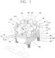
- FIG. 1 is a see-through perspective view illustrating an example of a shell of an example of a reciprocating compressor
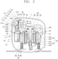
- FIG. 2 is a cross-sectional view illustrating an example of an inside of the reciprocating compressor of FIG. 1 .
- a reciprocating compressor can include a shell 110 that defines an outer appearance, an electric motor (or motor unit) 120 that is provided at an inner space 110a of the shell 110 and provides a driving force, a compression unit 140 that compresses a refrigerant by receiving the driving force from the electric motor 120, a suction and discharge part 150 that guides a refrigerant to a compression chamber and discharges a compressed refrigerant, and a support part 160 that supports a compressor body C including the electric motor 120 and the compression unit 140 with respect to the shell 110.
- an electric motor (or motor unit) 120 that is provided at an inner space 110a of the shell 110 and provides a driving force
- a compression unit 140 that compresses a refrigerant by receiving the driving force from the electric motor 120
- a suction and discharge part 150 that guides a refrigerant to a compression chamber and discharges a compressed refrigerant
- a support part 160 that supports a compressor body C including the electric motor 120 and the compression unit 140 with respect to the shell 110
- the shell 110 can include a lower shell 111 and an upper shell 112.
- the lower shell 111 and the upper shell 112 can be coupled to each other and define a hermetically sealed inner space 110a.
- the electric motor 120 and the compression unit 140 are accommodated in the inner space 110a of the shell 110.
- the shell 110 is made of an aluminum alloy (hereinafter, abbreviated as "aluminum”) that is lightweight and has a high thermal conductivity.
- the lower shell 111 can have a substantially hemisphere shape.
- a suction pipe 115, a discharge pipe 116, and a process pipe are coupled to the lower shell 111 in a penetrating manner.
- the suction pipe 115, the discharge pipe 116, and the process pipe can be coupled to the lower shell 111 by insert die casting.
- the upper shell 112 has a substantially hemispherical shape like the lower shell 111.
- the upper shell 112 is coupled from above to the lower shell 111 to thereby define the inner space 110a of the shell 110.
- the upper shell 112 and the lower shell 111 can be coupled by welding.
- the upper shell 112 and the lower shell 111 can be coupled by a bolt when they are made of an aluminum material that is not suitable for welding.
- the electric motor 120 includes a stator 121 and a rotor 122.
- the stator 121 is elastically supported with respect to the inner space 110a of the shell 110, namely, a bottom surface of the lower shell 111, and the rotor 122 is rotatably installed inside the stator 121.
- the stator 121 includes a stator core 1211 and a stator coil 1212.
- the stator core 1211 is made of a metal material, such as an electrical steel sheet, and performs electromagnetic interaction with the stator coil 1212 and the rotor 122 described hereinafter through an electromagnetic force when a voltage is applied to the electric motor 120 from the outside.
- the stator core 1211 has a substantially rectangular cylinder shape.
- an inner circumferential surface of the stator core 1211 can be formed in a circular shape, and an outer circumferential surface thereof can be formed in a rectangular shape.
- the stator core 1211 is fixed to a lower surface of a main bearing 141 by a stator coupling bolt.
- a lower end of the stator core 1211 is supported with respect to a bottom surface of the shell 110 by a support spring 161 to be described hereinafter in a state that the stator core 1211 is axially and radially spaced apart from an inner surface of the shell 110. This can reduce or prevent vibration generated during operation from being directly transferred to the shell 110.
- the stator coil 1212 is wound inside the stator core 1211. When a voltage is applied from the outside, the stator coil 1212 generates an electromagnetic force to perform electromagnetic interaction with the stator core 1211 and the rotor 122. This can allow the electric motor 120 to generate a driving force that causes the compression unit 140 to perform a reciprocating motion.
- an insulator 1213 can be disposed between the stator core 1211 and the stator coil 1212. This can help to prevent direct contact between the stator core 1211 and the stator coil 1212 to thereby facilitate the electromagnetic interaction.
- the rotor 122 includes a rotor core 1221, permeant magnets 1222, a connection part 1231, and an inertial core 1232.
- the rotor core 1221 can be made of a metal material such as an electrical steel plate, and a shaft hole 1221a to which a rotating shaft 130 defining a motor shaft is press-fitted and coupled can be formed at a center of the rotor core 1221.
- the shaft hole 1221a can be formed through the rotor core 1221 in an axial direction, such that the rotor core 1221 has a cylindrical shape.
- a motor shaft is usually referred to as a crank shaft.
- the motor shaft will be hereinafter referred to as a rotating shaft.
- the rotating shaft 130 includes a main shaft portion 131 and an eccentric shaft portion 133 provided at opposite ends of a plate portion 132 in the axial direction.
- a connecting rod 143 defining a portion of the compression unit 140 to be described hereinafter is rotatably coupled to the eccentric shaft portion 133, and a piston 142 defining a portion of the compression unit 140 to be described hereinafter can be coupled to an end of the connecting rod 143. Accordingly, when a voltage is applied to the rotor 122, the rotating shaft 130 rotates together with the rotor 122 to thereby transmit a rotational force of the electric motor 120 to the compression unit 140.
- a magnet mounting hole 1221b in which the permanent magnet 1222 is inserted can be formed through an edge of the rotor core 1221 in the axial direction.
- the magnet mounting hole 1221b can be provided in plurality to be disposed at predetermined intervals in a circumferential direction.
- a plurality of magnet mounting holes 1221b can be formed with respect to the shaft hole 1221a.
- the magnet mounting hole 1221b can be formed through both ends or a portion of the rotor core 1221 in the axial direction according to a shape of the rotor core 1221.
- the magnet mounting hole 1221b can be formed through the both ends of the rotor core 1221 in the axial direction.
- the magnet mounting hole 1221b can be formed only at the rotor core 1221 located at an inside of the stator core 1211. The rotor core 1221 will be described later together with the connection part 1231 and the inertial core 1232.
- the permanent magnets 1222 can be inserted into the respective magnet mounting holes 1221b at equal intervals in a circumferential direction of the rotor core 1221.
- the permanent magnets 1222 can each have a rectangular cross-sectional shape to be elongated in the axial direction.
- An axial length of the permanent magnet 1222 can be substantially the same as an axial length of the rotor core 1221. Accordingly, once the permanent magnet 1222 is inserted into the magnet mounting hole 1221b of the rotor core 1221, the permanent magnet 1222 is not separated therefrom due to the connection part 1231 to be described hereinafter. The permanent magnet 1222 will be described later together with the connection part 1231 and the inertial core 1232.
- the compression unit 140 includes the main bearing 141 and the piston 142.
- the main bearing 141 is elastically supported on the shell 110, and the piston 142 is coupled to the rotating shaft 130 by the connecting rod 143 to perform a relative motion with respect to the main bearing 141.
- the main bearing 141 is provided at an upper side of the electric motor 120.
- the main bearing 141 includes a frame 1411 (or frame portion), a fixing protrusion 1412 coupled to the stator 121 of the electric motor 120, a bearing portion 1413 (or shaft receiving portion) that supports the rotating shaft 130, and a cylinder unit (cylinder) 1415 that defines a compression chamber 141a.
- the frame 1411 can have a flat plate shape extending in a horizontal direction, or a radial plate shape by processing a portion of an edge excluding corners to reduce weight or thickness.
- the fixing protrusion 1412 is provided at an edge of the frame 1411.
- the fixing protrusion 1412 can protrude from the edge of the frame 1411 toward the electric motor 120, namely, in a downward direction.
- the main bearing 141 and the stator 121 can be coupled by a stator coupling bolt to be elastically supported on the lower shell 111 together with the stator 121 of the electric motor 120.
- the bearing portion 1413 can axially extend from a central portion of the frame 1411 in opposite directions.
- a bearing hole 1413a can be axially formed through the bearing portion 1413 so as to allow the rotating shaft 130 to penetrate therethrough, and a bush bearing can be insertedly coupled to an inner circumferential surface of the bearing hole 1413a.
- the plate portion 132 of the rotating shaft 130 can be supported on an upper end of the bearing portion 1413 in the axial direction, and the main shaft portion 131 of the rotating shaft 130 can be supported on an inner circumferential surface of the bearing portion 1413 in a radial direction. Accordingly, the rotating shaft 130 can be axially and radially supported by the main bearing 141.
- the cylinder unit (hereinafter, abbreviated as "cylinder") 1415 is radially eccentric from an edge of one side of the frame 1411.
- the cylinder 1415 is formed through the main bearing 141 in the radial direction so that the piston 142 connected to the connecting rod 143 is inserted into an inner open end thereof, and a valve assembly 151 defining the suction and discharge part 150 to be described hereinafter is inserted into an outer open end thereof.
- the piston 142 is configured such that a side (a rear side) that faces the connecting rod 143 is open and an opposite side thereof, namely, a front side is closed. Accordingly, the connecting rod 143 is inserted into the rear side of the piston 142 to be rotatably coupled, and the front side of the piston 142 is formed in a closed shape to define the compression chamber 141a inside the cylinder 1415 together with the valve assembly 151 to be described hereinafter.
- the piston 142 can be made of the same material as the main bearing 141, such as an aluminum alloy. This can help to prevent a magnetic flux from being transmitted to the piston 142 from the rotor 122.
- the piston 142 is made of the same material as the main bearing 141, the piston 142 and the main bearing 141 (more precisely, the cylinder) can have the same coefficient of thermal expansion. Accordingly, even when the inner space 110a of the shell 110 is in high temperature condition (approximately 100°C) during operation of the compressor, interference between the main bearing 141 and the piston 142, caused by thermal expansion, can be suppressed or reduced.
- the suction and discharge part 150 includes the valve assembly 151, a suction muffler 152, and a discharge muffler 153.
- the valve assembly 151 and the suction muffler 152 are sequentially coupled from the outer open end of the cylinder 1415.
- the valve assembly 151 includes a valve plate 1511, a suction valve 1512, a discharge valve 1513, a valve stopper 1514, and a discharge cover 1515.
- the valve plate 1511 has a substantially rectangular plate shape and is installed to cover a front-end surface of the main bearing 141, namely, a front open surface of the compression chamber 141a.
- a coupling hole is provided at each corner of the valve plate 1511, so as to be coupled to a coupling groove formed on the front-end surface of the main bearing 141 by a bolt.
- one suction port 1511a and at least one discharge port 1511b can be defined in the valve plate 1511.
- the suction port 1511a can be formed at a central portion of the valve plate 1511, and the plurality of discharge ports 1511b can be formed along a circumference of the suction port 1511a to be spaced apart by predetermined intervals or gaps.
- the suction valve 1512 can be disposed at a side facing the piston 142 based on the valve plate 1511. Accordingly, the suction valve 1512 can be bent in a direction toward the piston 142 to be opened and closed.
- the discharge valve 1513 can be disposed at an opposite side of the piston 142 based on the valve plate 1511. Accordingly, the discharge valve 1513 can be bent in a direction opposite to the piston 142 to be opened and closed.
- the valve stopper 1514 can be disposed between the valve plate 1511 and the discharge cover 1515 with the discharge valve 1513 interposed therebetween.
- the valve stopper 1514 is fixed by being pressed by the discharge cover 1515 in a state that one end thereof is in contact with a fixing portion of the discharge valve 1513.
- the discharge cover 1515 can be coupled to the front-end surface of the main bearing 141 with the valve plate 1511 interposed therebetween, allowing the compression chamber 141a to be finally covered by the discharge cover 1515. Therefore, the discharge cover 1515 can also be referred to as a "cylinder cover”.
- the suction muffler 152 can be fixed by the valve assembly 151 to communicate with the suction port 1511a of the valve plate 1511. Accordingly, the suction muffler 152 transfers a refrigerant suctioned through the suction pipe 115 to the compression chamber 141a of the cylinder 1415.
- the suction muffler 152 is provided therein with a suction space portion.
- An inlet (or entrance) of the suction space portion communicates with the suction pipe 115 in a direct or indirect manner, and an outlet (or exit) of the suction space portion directly communicates with a suction side of the valve assembly 151.
- the discharge muffler 153 can be installed separately from the main bearing 141.
- the discharge muffler 153 is provided therein with a discharge space portion.
- An inlet of the discharge space portion can be connected to a discharge side of the valve assembly 151 by a loop pipe 118, and an outlet of the discharge space portion can be directly connected to the discharge pipe 116 by the loop pipe 118.
- the support parts 160 can support between a lower surface of the electric motor 120 and the bottom surface of the lower shell 111 that faces the lower surface the electric motor 120, which, for example, support four corners of the electric motor 120 with respect to the shell 110.
- each of the support parts 160 can include a support spring 161, a first spring cap 162 that supports a lower end of the support spring 161, and a second spring cap 163.
- each support part 160 defines one unitary support assembly made up of the support spring 161, the first spring cap 162, and the second spring cap 163, and the unitary support assemblies can be installed along a periphery of the compressor body at predetermined intervals.
- the support spring 161 is configured as a compression coil spring.
- the first spring cap 162 is fixed to the bottom surface of the lower shell 111 to support the lower end of the support spring 161, and the second spring cap 163 is fixed to a lower end of the electric motor 120 to support an upper end of the support spring 161. Accordingly, the support springs 161 are supported by the respective first spring caps 162 and the respective second spring caps 163, so as to elastically support the compressor body C with respect to the shell 110.
- an unexplained reference numeral 110b denotes an oil storage space.
- the reciprocating compressor described above can operate as follows.
- the rotor 122 rotates.
- the rotating shaft 130 coupled to the rotor 122 rotates together, causing a rotational force to be transferred to the piston 142 through the connecting rod 143.
- the connecting rod 143 allows the piston 142 to perform a reciprocating motion in a front and rear direction (or back and forth) with respect to the cylinder 1415.
- volume of the compression chamber 141a increases.
- a refrigerant filled in the suction muffler 152 passes through the suction valve 1512 of the valve assembly 151, and is then suctioned into the compression chamber 141a of the cylinder 1415.
- volume of the compression chamber 131a decreases.
- a refrigerant filled in the compression chamber 141a is compressed, passes through the discharge valve 1513 of the valve assembly 151, and is then discharged to a discharge chamber 1515a of the discharge cover 1515.
- This refrigerant flows into the discharge space portion of the discharge muffler 153 through the loop pipe 118 and is then discharged to a refrigeration cycle through the loop pipe 118 and the discharge pipe 116.
- Such series of processes are repeated.
- both the electric motor defining the motor unit and the compression unit are installed in the shell.
- a size of the electric motor is also decreased, and a size of the rotor defining a portion of the electric motor is reduced accordingly.
- a smaller rotor leads to a decrease in rotational inertia, which can be disadvantageous in terms of motor efficiency.
- the rotor can be further provided with an inertial core for compensating the decrease of the rotational inertia while achieving the size reduction of the rotor and the compressor.
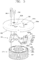
- FIG. 3 is an exploded perspective view illustrating examples of an inertial core and a rotor
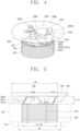
- FIG. 4 is a perspective view illustrating an example of a coupled state of the inertial core and the rotor
- FIG. 5 is a front view of FIG. 4 .
- the rotor 122 can include the rotor core 1221 and the permanent magnets 1222 as described above.
- One shaft hole 1221a to which the rotating shaft 130 is press-fitted can be defined at the center of the rotor core 1221, and a plurality of magnet mounting holes 1221b in which the respective permanent magnets 1222 are inserted can be formed at the edge of the rotor core 1221.
- the shaft hole 1221a and the magnet mounting holes 1221b can be formed through the rotor core 1221 in the axial direction, and the plurality of magnet mounting holes 1221b can be formed at the edge of the rotor core 1221 to be spaced apart by predetermined intervals in the circumferential direction.
- the shaft hole 1221a can have a circular cross-sectional shape to correspond to an outer surface of the rotating shaft 130, and the magnet mounting hole 1221b can have a rectangular cross-sectional shape to correspond to an outer surface of the permanent magnet 1222.
- the rotor core 1221 can be formed by stacking a plurality of thin electrical steel sheets in the axial direction.
- a first coupling hole 1221c is formed through the rotor core 1221 in the axial direction, and a first coupling member 1241, such as a bolt and a rivet, is inserted into the first coupling hole 1221c so that the plurality of electrical steel sheets can be stacked together.
- the first coupling hole 1221c can be provided in plurality to be disposed between the shaft hole 1221a and the magnet mounting holes 1221b at predetermined intervals in the circumferential direction.
- the rotor core 1221 can be formed by stacking thin electrical steel sheets having the same shape in the axial direction, such that the rotor core 1221 can have the same shape in the axial direction.
- the rotor core 1221 can be formed by stacking thin electrical steel sheets having different shapes, such that the rotor core 1221 can have different shapes in the axial direction.
- the rotor core 1221 can be formed in a shape having one outer diameter, or a shape having a plurality of outer diameters in the axial direction.
- the former can be referred to as a "single-stage rotor core” and the latter can be referred to as a "multi-stage rotor core.”
- the single-stage rotor core is used as a representative example, but the basic structure can be equally applied to the multi-stage rotor core.
- the rotor core can be understood as the single-stage rotor core unless otherwise specified.
- the inertial core 1232 can be provided at one end of the rotor 122 in the axial direction, more precisely, at one end of the rotor core 1221 in the axial direction.
- the inertial core 1232 can be installed at an upper or lower end of the rotor core 1221, or both the upper and lower ends of the rotor core 1221 according to the shape of a compressor in which the electric motor 120 is installed.
- an example in which the inertial core 1232 is installed at the upper end of the rotor core 1221 will be described.
- the inertial core 1232 can be coupled to the upper end of the rotor core 1221 with the connection part 1231 interposed therebetween.
- connection part 1231 is a part that is coupled to the rotor core 1221
- the inertial core 1232 is a part that is spaced apart from the rotor core 1221.
- a horizontal cross-sectional area at a middle height (or point) of the connection part 1231 in the axial direction can be smaller than a horizontal cross-sectional area at a middle height of the rotor core 1221 in the axial direction, and a horizontal cross-sectional area at a middle height of the inertial core 1232 in the axial direction can be larger than the horizontal cross-sectional area at the middle height of the rotor core 1221 in the axial direction.
- connection part 1231 an amount of use of the connection part 1231 can be reduced, a contact area between the connection part 1231 and the permanent magnets 1222 can be reduced, and a fluid flow path F to be described hereinafter can be provided in the connection part 1231 by providing communication between the inside and the outside of the connection part 1231 or reducing the horizontal cross-sectional area.
- connection part 1231 and the inertial core 1232 can be formed as a single body, or separately formed and assembled together.
- connection part 1231 and the inertial core 1232 are formed as a single body, it can be advantageous in terms of assemblability, and when the connection part 1231 and the inertial core 1232 are separately provided, it can be advantageous in terms of manufacturing cost and magnetic flux leakage reduction.
- the connection part 1231 and the inertial core 1232 can be separately formed, which will be described.
- the connection part 1231 and the inertial core 1232 can be formed as a single body, which will be described later.
- connection part 1231 and the inertial core 1232 can have the same property or different properties with respect to a magnetic property.
- both the connection part 1231 and the inertial core 1232 are non-magnetic, it can be suitable for suppressing magnetic flux leakage.
- both of the connection part 1231 and the inertial core 1232 are magnetic, it can be advantageous in terms of manufacturing costs.
- the connection part 1231 can be made of a non-magnetic material, and the inertial core 1232 can be made of a magnetic material, which will be described.
- both the connection part 1231 and the inertial core 1232 can be made of magnetic materials, which will be described later.
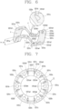
- FIG. 6 is an enlarged perspective view illustrating an example of a connection part of FIG. 3
- FIG. 7 is a planar view of FIG. 6
- FIG. 8 is an enlarged planar view illustrating a portion "A" of FIG. 7 .
- connection part 1231 can be configured as a single body with an annular shape.
- the connection part 1231 can be formed in a wavy or zigzag shape along the circumferential direction.
- connection part 1231 can include a plurality of first fixing portions 1231a, a plurality of second fixing portions 1231b, and a plurality of link portions 1231c.
- the plurality of first fixing portions 1231a and the plurality of second fixing portions 1231b can be alternately disposed along the circumferential direction when projected in the axial direction, and the plurality of link portions 1231c can be inclined opposite to each other when projected in the radial direction.
- one first fixing portion 1231a, one second fixing portion 1231b, and one link portion 1231c will be used as representative examples for description.
- the first fixing portion 1231a that is supported on an axial end surface of the rotor core 1221 (or an end surface of the rotor core 1221 in the axial direction) can be flat when projected in the radial direction. Accordingly, the first fixing portion 1231a can be securely supported on the end surface of the rotor core 1221 in the axial direction.
- the first fixing portion 1231a can include a first inner arcuate end portion 1231a1, a first outer arcuate end portion 1231a2, and a plurality of first linear end portions connecting both ends of the first inner arcuate end portion 1231a1 and both ends of the first outer arcuate end portion 1231a2 facing each other. Accordingly, the first fixing portion 1231a can have a sectoral shape in which an arc length of its outer circumferential surface is greater (longer) than an arc length of its inner circumferential surface when projected in the axial direction.
- the first fixing portion 1231a can be formed such that a radial center line passes through its circumferential center to pass through a center of the rotating shaft 130, namely a center of the rotor 122. Accordingly, centrifugal force acting on the first fixing portion 1231a can be evenly distributed, allowing the first fixing portion 1231a to be securely supported on the rotor core 1221.
- one axial surface (e.g., a lower surface) of the first fixing portion 1231a can be formed to correspond to an axial end surface (e.g., an upper surface) of the rotor core 1221 that faces the first fixing portion 1231a in the axial direction.
- the lower surface of the first fixing portion 1231a can be formed flat like the upper surface of the rotor core 1221. As a contact area between the connection part 1231 and the rotor core 1221 is secured, the connection part 1231 can be securely supported on the rotor core 1221.
- the plurality of first fixing portions 1231a can have the same arc angle along the circumferential direction.
- the plurality of first fixing portions 1231a can be disposed at equal intervals in the circumferential direction. This can allow a circumferential support force of the connection part 1231 to be evenly distributed, and thus, the connection part 1231 can be securely supported on the rotor core 1221.
- the first fixing portion 1231a can be provided at a position where at least a portion or part thereof radially overlaps one axial end (upper end) of the permanent magnet 1222.
- each of the first fixing portions 1231a can be disposed over ends of two permanent magnets 1222 facing each other in the circumferential direction, which can be suitable for fixing the permanent magnets 1222.
- first end a left end in the drawing
- second end a right end in the drawing
- one fixing portion 1231a can be disposed in a radially overlapping manner over a second end (right end in the drawing) of a first permanent magnet 1222a and a first end (left end in the drawing) of a second permanent magnet 1222b facing each other in the circumferential direction.
- Another first fixing portion 1231a can be disposed in a radially overlapping manner over a second end of a third permanent magnet 1222c and a first end of a fourth permanent magnet 1222d facing each other in the circumferential direction.
- the other first fixing portion 1231a can be disposed in a radially overlapping manner over a second end of a fifth permanent magnet 1222e and a first end of a sixth permanent magnet 1222f facing each other in the circumferential direction.
- a circumferential center of each of the three first fixing portions 1231a can be disposed between two adjacent permanent magnets 1222 to thereby cover and support the two permanent magnets 1222 in the axial direction.
- one axial ends (upper ends) of the six permanent magnets 1222 can be covered and supported in the axial direction by the three first fixing portions 1231a.
- a second coupling hole 1231a4 can be defined in a central part of the first fixing portion 1231a to be disposed at a position that does not overlap the permanent magnet 1222, for example, on the same axis as the first coupling hole 1221c of the rotor core 1221. Accordingly, the connection part 1231 can be coupled by the first coupling member 1241 that passes through the second coupling hole 1231a4 and the first coupling hole 1221c.
- the second fixing portion 1231b which is a part supported on the inertial core 1232, can be formed flat when projected in the radial direction. Accordingly, the second fixing portion 1231b can be securely supported on the inertial core 1232.
- One axial surface (upper surface) of the second fixing portion 1231b facing the inertial core 1232 can be formed to correspond to one axial surface (lower surface) of the inertial core 1232.
- the upper surface of the second fixing portion 1231b can be formed flat the same as a lower surface of the inertial core 1232.
- a rotation prevention groove in which the second fixing portion 1231b is inserted to be supported in the circumferential direction can be formed on the lower surface of the inertial core 1232.
- the second fixing portion 1231b can include a second inner arcuate end portion 1231b1, a second outer arcuate end portion 1231b2, and a plurality of second linear end portions 1231b3 connecting both ends of the second inner arcuate end portion 1231b1 and both ends of the second outer arcuate end portion 1231b2. Accordingly, the second fixing portion 1231b can have a sectoral shape in which an arc length of its outer circumferential surface is greater (longer) than an arc length of its inner circumferential surface when projected in the axial direction.
- An area of the second fixing portion 1231b can be substantially the same as an area of the first fixing portion 1231a. Accordingly, the inertial core 1232 supported on the second fixing portion 1231b can be securely supported.
- the second fixing portion 1231b can be formed between two first fixing portions 1231a along the circumferential direction when projected in the axial direction.
- the plurality of second fixing portions 1231b can be disposed at equal intervals to have the same arc angle in the circumferential direction. Accordingly, a circumferential support force of the connection part 1231 is evenly distributed to thereby securely support the inertial core 1232.
- a third coupling hole 1231b4 is formed at each of the second fixing portions 1231b.
- the third coupling hole 1231b4 can be disposed on the same axis as a fourth coupling hole 1232d of the inertial core 1232 to be described hereinafter.
- the link portion 1231c is a portion that connects the first fixing portion 1231a and the second fixing portion 1231b.
- the plurality of link portions 1231c can be bent opposite to each other along the circumferential direction when projected in the radial direction.
- one first link portion 1231c can be bent upward from a second end (left end in the drawing) of one first fixing portion 1231a located on the lower side in the axial direction to a first end (right end in the drawing) of one second fixing portion 1231b located on the upper side in the axial direction, and another link portion 1231c can be bent downward from a second end of the one second fixing portion 1231b to a first end of another first fixing portion 1231a.
- the link portions 1231c can be formed in a wavy or zigzag shape in the circumferential direction.
- Each of the link portions 1231c can be bent at a right angle.
- one link portion 1231c can be bent at a right angle from a second end of one first fixing portion 1231a to be connected to a first end of one second fixing portion 1231b
- another link portion 1231c can be bent at a right angle from a second end of the one second fixing portion 1231b to be connected to a first end of another first fixing portion 1231a.
- first fixing portions 1231a and the second fixing portions 1231b are arranged continuously in the circumferential direction when projected in the axial direction, support areas of the first fixing portions 1231a and the second fixing portions 1231b can be increased and axial support forces of the link portions 1231c can be enhanced when the inertial core 1232 is coupled to the rotor core 1221 in the axial direction.
- the link portions 1231c can be obliquely or inclinedly bent in alternatively opposite directions along the circumferential direction.
- one link portion 1231c can be obliquely bent from a second end of one first fixing portion 1231a to be connected to a first end of one second fixing portion 1231b
- another link portion 1231c can be obliquely bent from a second end of the one second fixing portion 1231b to be connected to a first end of another first fixing portion 1231a.
- the first fixing portions 1231a and the second fixing portions 1231b are disposed at predetermined intervals in the circumferential direction when projected in the axial direction, the amount of use of the connection part 1231 can be reduced accordingly. This is advantageous to reduce manufacturing costs considering that the connection part 1231 is a relatively expensive non-magnetic material.
- the link portions 1231c can be bent, curved, or inclined.
- the link portion 1231c can be formed in an arcuate shape having both side surfaces in the circumferential direction parallel to each other when projected in the axial direction. Accordingly, outer and inner circumference lengths of the link portion 1231c that connects the first fixing portion 1231a and the second fixing portion 1231b can be the same, and thus, outer circumferential heights and inner circumferential heights of the first fixing portion 1231a and the second fixing portion 1231b can be the same.
- the link portion 1231c defines a gap or distance ⁇ h between the first fixing portion 1231a and the second fixing portion 1231b as described above.
- a slope ⁇ of the link portion 1231c determines an axial height h of the link portion 1231c
- the axial height h of the link portion 1231c determines the distance ⁇ h between the first fixing portion 1231a and the second fixing portion 1231b. Therefore, the larger the slope ⁇ of the link portion 1231c, the greater the distance ⁇ h between the first fixing portion 1231a and the second fixing portion 1231b.
- the gap ⁇ h between the first fixing portion 1231a and the second fixing portion 1231b can also be referred to as an "insulation distance.”
- the slope ⁇ of the link portion 1231c can be formed such that the insulation distance (a height of the link portion, a height of the connection part, or a height of the non-magnetic material) ⁇ h between the first fixing portion 1231a and the second fixing portion 1231b can be greater than or equal to an axial length (thickness) t of the inertial core 1232 to be described hereinafter.
- the insulation distance ⁇ h can be less than a thickness t of the inertial core 1232.
- an appropriate insulation distance ⁇ h between the inertial core 1232 and the permanent magnet 1222 can be provided to suppress magnetic flux leakage.
- FIG. 9 is a graph showing this relationship.
- Table 1 Height of non-magnetic material (mm) Back electromotive force (BEMF) Reduction rate of BEMF (%) 0 34.44 74.3 1 44.05 95.0 2 44.95 97.0 3 45.76 98.7 4 46.01 99.3 5 46.04 99.3 6 46.17 99.6
- the height (insulation distance) h of the connection part 1231 which is the non-magnetic material, should be less than or equal to the thickness t of the inertial core 1232, which is the magnetic material, and should be approximately 4 mm or more in order to suppress magnetic flux leakage.
- the slope of the link portion 1231c can be greater than or equal to 20° (degrees) and less than 90° (degrees) with respect to an end surface of the rotor core 1221 in the axial direction (or an axial end surface of the rotor core 1221).
- connection part 1231 As the connection part 1231 according to the present disclosure is formed by bending a thin plate, the connection part 1231 can have a horizontal cross-sectional area smaller than a horizontal cross-sectional area of the rotor core 1221.
- a fluid flow path F can be provided between the rotor core 1221 and the inertial core 1232 as the inside and outside of the connection part 1231 communicates with each other. Accordingly, a fluid in a periphery of the connection part 1231 can flow through the fluid flow path F when the rotor 122 rotates, allowing fluid resistance generated in the periphery of the connection part 1231 and the inertial core 1232 to be reduced when the rotor 122 rotates. As a result, a decrease in efficiency of the motor can be suppressed.
- the link portion 1231c As both side surfaces of the link portion 1231c in the circumferential direction are parallel to each other when projected in the axial direction, the link portion 1231c, as illustrated in FIG. 8 , can be inclined with respect to the circumferential direction when projected in the axial direction.
- the connection part 1231 rotates together with the rotor 122, fluid resistance in the link portion 1231c can be reduced to thereby more effectively suppress a decrease in the motor efficiency.
- bending line portions 1231d can be formed between the first fixing portion 1231a and the link portion 1231c, and between the link portion 1231c and the second fixing portion 1231b, respectively.
- the bending line portions 1231d define the first linear end portion 1231a3 or the second linear end portion 1231b3 defining both ends of the first fixing portion 1231a or the second fixing portion 1231b. Accordingly, each of the link portions 1231c can be upwardly or downwardly bent from the first fixing portion 1231a or the second fixing portion 1231b with respect to the bending line portion 1231d defining the first fixing portion 1231a or the second fixing portion 1231b.
- the bending line portion 1231d can be provided with a reinforcing rib 1231d1 to help to prevent a decrease in strength due to stress concentration in the bending line portion 1231d.
- the reinforcing rib 1231d1 can protrude from a center of the bending line portion 1231d in a direction in which the link portion 1231c is bent, namely, to an inner surface of the bending line portion 1231d. This can help to prevent buckling of the relatively thin link portion 1231c due to a coupling force caused when the inertial core 1232 is coupled to the rotor core 1221 or deformation of the link portion 1231c caused by centrifugal force generated when the rotor 122 rotates. Accordingly, rigidity of the bending line portion 1231d can be increased to thereby enhance the reliability of the connection part 1231.
- the reinforcing rib 1231d1 can pass through the bending line portion 1231d in the circumferential direction such that its one end is connected to the first fixing portion 1231a or the second fixing portion 1231b and its another end is connected to the link portion 1231c.
- connection part 1231 is formed in a wavy or zigzag shape by pressing a thin plate material
- the reinforcing rib 1231d1 can be formed together while the connection part 1231 is pressing processed. Accordingly, the reinforcing rib 1231d1 can be recessed by being pressed from an outer surface to inner surface of the bending line portion 1231d.
- connection part 1231 is made of a material having plasticity such as stainless steel
- the reinforcing rib 1231d1 can be formed in various ways depending on the material of the connection part 1231.
- the connection part 1231 has elasticity such as plastic
- the outer surface of the bending line portion 1231d can be formed flat and the reinforcing rib 1231d1 can protrude only to the inner surface of the bending line portion 1231d.
- the reinforcing rib 1231d1 can be provided at the center of the bending line portion 1231d, and a length of the reinforcing rib 1231d1 in a widthwise direction can be approximately less than half of a length of the bending line portion 1231d in the widthwise direction in consideration of stability, which can be more advantageous in terms of strength.
- the inertial core 1232 can have an annular shape, and be coupled by being supported on the upper surfaces of the second fixing portions 1231b of the connection part 1231.
- the inertial core 1232 can be made of a magnetic material as described above.
- the inertial core 1232 can be made of steel or a similar material.
- the inertial core 1232 made of the magnetic material can be inexpensive and have a higher density compared to an inertial core entirely made of a non-magnetic material to thereby increase rotational inertia (moment of inertia) in relation to a cross-sectional area of the inertial core 1232.
- a bearing portion through hole 1232b can be formed through a center of a body portion 1232a of the inertial core 1232.
- the bearing portion through hole 1232b can be a hole through which a bearing portion 1413 of the main bearing 141 penetrates in the axial direction, and its center can be located on the same axis as a rotation center of the rotating shaft 130 (a rotation center of the rotor). Accordingly, the body portion 1232a of the inertial core 1232 can produce a uniform centrifugal force along the radial direction when the rotor 122 rotates.
- the bearing portion through hole 1232b can be formed in a circular shape having one inner diameter.
- the connection part 1231 and the inertial core 1232 are assembled together before coupling the connection part 1231 to the rotor core 1221, the second coupling hole 1231a4 of the connection part 1231 and the first coupling hole 1221c of the rotor core 1221 are covered or blocked by a peripheral portion of the bearing portion through hole 1232b. Then, the first coupling member 1241 cannot be inserted from the inertial core 1232 into the rotor core 1221.
- coupling member insertion grooves 1232c can extend to be recessed into an inner circumferential surface of the bearing portion through hole 1232b in the radial direction.
- the coupling member insertion groove 1232c can be formed on the same axis as the second coupling hole 1231a4 of the connection part 1231 and the first coupling hole 1221c of the rotor core 1221 when projected in the axial direction. Accordingly, when the connection part 1231 and the inertial core 1232 are assembled together prior to assembling the connection part 1231 to the rotor core 1221, the first coupling member 1241 can be inserted from the inertial core 1232 into the rotor core 1221 through the coupling member insertion groove 1232c.
- the fourth coupling hole 1232d can be formed on the body portion 1232a of the inertial core 1232.
- a plurality of fourth coupling holes 1232d can be defined in a periphery of the bearing portion through hole 1232b to be spaced apart by predetermined intervals in the circumferential direction.
- the fourth coupling holes 1232d can be formed on the same circumference as the coupling member insertion grooves 1232c to be disposed at equal intervals between the coupling member insertion grooves 1232c so as not to overlap the coupling member insertion grooves 1232c.
- the fourth coupling hole 1232d can be formed on the same axis as the third coupling hole 1231b4 such that the connection part 1231 and the inertial core 1232 can be coupled by a second coupling member 1242 passing through the fourth coupling hole 1232d and the third coupling hole 1231b4.
- the number of the fourth coupling holes 1232d can correspond to the number of the first coupling holes 1221c.
- the fourth coupling holes 1232d of the inertial core 1232 can be formed only in portions corresponding to the third coupling holes 1231b4 of the connection part 1231.
- the inertial core 1232 can be formed as wide as possible, which is advantageous in terms of rotational inertia.
- an outer diameter of the inertial core 1232 can be greater than an air gap between the stator 121 and the rotor 122.
- an outer diameter D2 of the inertial core 1232 can be greater than an inner diameter D3 of the stator coil 1212 (more precisely, a bundle of coils wound on an upper end of the stator core 1211 into an annular shape) such that a portion of the inertial core 1232 overlaps the stator coil 1212 in the radial direction. Accordingly, the outer diameter D2 of the inertial core 1232 can be much greater than an outer diameter D4 of the rotor core 1221.
- an outer diameter D1 of the connection part 1231 can be less than the outer diameter D2 of the inertial core 1232, and substantially the same as the outer diameter D4 of the rotor core 1221.
- the thickness t of the inertial core 1232 As described above, by forming the thickness t of the inertial core 1232 as thin as possible to make the inertial core 1232 farther away from the permanent magnet 1222 as possible, magnetic flux leakage of the permanent magnet 1222 can be suppressed.
- centrifugal force of the inertial core 1232 can be enhanced by increasing the outer diameter D2 of the inertial core 1232. Accordingly, rotational inertia of the inertial core 1232 can be increased to thereby suppress a decrease in efficiency of the motor and the compressor while reducing the size of the electric motor.
- a volume of the inertial core 1232 can be determined by rotational inertia of the rotor 122 excluding the connection part 1231 and the inertial core 1232.
- rotational inertia of a rotating body including the rotor 122, the connection part 1231, and the inertial core 123 is related to efficiency of the compressor. If the rotational inertia of the rotating body is too low or too high, the efficiency of the compressor can be reduced. Therefore, a range of the rotational inertia of the rotating body should be appropriately secured (or determined) for the efficiency of the compressor.
- the rotational inertia of the rotor 122 is predetermined by the size (capacity) of the electric motor 120, the rotational inertia of the inertial core 1232 (or the connection part included) can be a value obtained by subtracting rotational inertia of the rotor 122 from appropriate rotational inertia of the rotating body.
- FIG. 10 is a graph showing the compressor efficiency with respect to rotational inertia of a rotor including an inertial core.
- an x-axis represents a ratio calculated by dividing rotational inertia of the inertial core 1232 (or including the connection part) by rotational inertia of the rotor 122, and a y-axis indicates the efficiency of the compressor.
- the graph shows that the rotational inertia of the inertial core 1232 should be greater than the rotational inertia of the rotor 122, and the ratio calculated by dividing the rotational inertia of the inertial core 1232 by the rotational inertia of the rotor 122 should be in the range of 110 to 300%.
- connection part is bent in the zigzag shape such that portions supporting the inertial core are spaced apart from the rotor core.
- the portions supporting the inertial core can be supported on the rotor core in the axial direction while being bent into the zigzag shape.
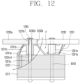
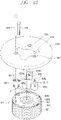
- FIG. 11 is an exploded perspective view illustrating an example of an inertial core
- FIG. 12 is an assembled front view of FIG. 11 .
- connection part 1231 can be coupled to an inertial core 1232 as described above.
- the connection part 1231 can be formed in a wavy or zigzag shape, and the inertial core 1232 can be implemented as a flat plate with an annular shape.
- connection part 1231 can include a plurality of first fixing portions 1231a, second fixing portions 1231b, and link portions 1231c as described above.
- the first fixing portions 1231a and the second fixing portions 1231b can be connected to each other by the link portions 1231c so as to have an annular shape.
- the first fixing portions 1231a can be supported on the rotor core 1221
- the second fixing portions 1231b can be supported on the inertial core 1232
- the link portions 1231c can be obliquely bent to connect the first fixing portions 1231a and the second fixing portions 1231b.
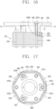
- first fixing portion 1231a The basic configurations of the first fixing portion 1231a, the second fixing portion 1231b, and the link portion 1231c are similar to those of the example described above, so a detailed description thereof will be omitted. In this example, however, boss portions 1231e extending from the first fixing portions 1231a and/or the second fixing portions 1231b in the axial direction can be further provided.
- the boss portion 1231e can extend from the connection part 1231 or the inertial core 1232. However, when the boss portion 1231e extends from the inertial core 1232 that is magnetic, magnetic flux leakage can be caused as the boss portion 1231e of a magnetic material is disposed adjacent to the permanent magnet 1222. Therefore, the boss portion 1231e can extend from the connection part 1231, which is non-magnetic, and help to prevent the magnetic flux leakage.
- the boss portions 1231e can extend from the first fixing portions 1231a toward the inertial core 1232, or extend from the second fixing portions 1231b toward the rotor core 1221.
- the boss portions 1231e extend from both of the first fixing portions 1231a and the second fixing portions 1231b will be described.
- the boss portions 1231e can axially extend from the first fixing portion 1231a and the second fixing portion 1231b of the connection part 1231, respectively.
- a fifth coupling hole 1231e1 can be formed through each of the boss portions 1231e in the axial direction.
- the fifth coupling hole 1231e1 can be formed on the same axis as the first coupling hole 1221c of the rotor core 1221, the second coupling hole 1231a4 of the first fixing portion 1231a (or the third coupling hole of the second fixing portion), and the fourth coupling hole 1232d of the inertial core 1232 in a communicating manner.
- a length of the boss portion 1231e can be approximately equal to a value obtained by subtracting a thickness of the first fixing portion 1231a (or the second fixing portion) from a height of the link portion 1231c, namely, a height of the connection part 1231. Accordingly, an upper end of the boss portion 1231e that extends from an upper surface of the first fixing portion 1231a can have substantially the same height as an upper surface of the second fixing portion 1231b, and a lower end of the boss portion 1231e that extends from a lower surface of the second fixing portion 1231b can have substantially the same height as a lower surface of the first fixing portion 1231a.
- the inertial core 1232 in this example is almost the same as the inertial core of the example described above, a detailed description thereof will be omitted.
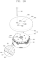
- a bearing portion through hole 1232b with a circular shape can be formed at the center of the inertial core 1232.
- the boss portion 1231e when the boss portion 1231e extends from the connection part 1231 in the axial direction, the boss portion 1231e can axially support the connection part 1231 with respect to the rotor core 1221. Accordingly, buckling of the connection part 1231 can be suppressed to thereby increase the reliability of the connection part 1231 and the inertial core 1232. In particular, buckling of the connection part 1231, which can be caused when the connection part 1231 is made of a non-metal such as plastic, can be effectively prevented.
- buckling of the connection part 1231 can be caused by a coupling force applied when coupling the coupling member 1243. This can be caused more when the connection part 1231 is a non-metal.
- the boss portion 1231e is provided at the connection part 1231, the buckling of the connection part 1231 can be effectively suppressed even when the third coupling members 1243 are coupled through the rotor core 1221 and the inertial core 1232 entirely in the axial direction.
- an inner circumferential surface of the inertial core 1232 can be formed in a circular shape to thereby achieve a simpler structure of the inertial core 1232. This can result in facilitating the manufacture of the inertial core 1232, and increasing weight of the inertial core 1232 in relation to its outer diameter, which is advantageous to increase rotational inertia.
- the rotor core 1221 and the inertial core 1232 can be coupled by the same third coupling member 1243. Accordingly, coupling of the rotor core 1221 and the inertial core 1232 can be simplified to thereby reduce manufacturing costs.
- a fluid flow path F can be formed between the link portions 1231c of the connection part 1231 as in the example described above. Accordingly, fluid resistance caused by the connection part 1231 and the inertial core 1232 when the rotor 122 rotates can be reduced while allowing the inertial core 1232 to be installed on the rotor 122.
- boss portions can be separated from the connection part and manufactured separately. Its basic structure and operational effects are similar to those of the example described above, a detailed description thereof will be omitted.
- connection part has the annular shape and is bent in the zigzag shape.
- connection part can have a boss shape extending in the axial direction.
- FIG. 13 is an exploded perspective view illustrating an example of an inertial core
- FIG. 14 is an assembled front view of FIG. 13 .
- connection part 1231 can be coupled to an inertial core 1232 as in the examples described above.
- the connection part 1231 can include a plurality of support bosses 1231f.
- the plurality of support bosses 1231f can be connected to each other by a connecting rib 1231g.
- the plurality of support bosses 1231f can have cross-sectional areas the same as or similar to the first fixing portions 1231a, as illustrated in FIG. 8 , and be disposed at the same positions as the first fixing portions 1231a. Accordingly, one support boss 1231f can support two permanent magnets 1222 respectively inserted into two permanent magnet mounting holes 1221b facing each other in the circumferential direction of the rotor core 1221.
- the plurality of support bosses 1231f can each have a fifth coupling hole 1231f1 formed therethrough in the axial direction.
- the fifth coupling hole 1231f1 can be formed on the same axis as the first coupling hole 1221c of the rotor core 1221 and the fourth coupling hole 1232d of the inertial core 1232. Accordingly, the inertial core 1232 can be coupled to the rotor core 1221 by the third coupling member 1243 with a long length that passes through the first coupling hole 1221c of the rotor core 1221, the fifth coupling hole 1231f1 of the support boss 1231f, and the fourth coupling hole 1232d of the inertial core 1232.
- Each of the plurality of support bosses 1231f can have an axial length that can allow the inertial core 1232 to secure an appropriate insulation distance h from the rotor core 1221, as in the examples described above. Accordingly, magnetic flux leakage from the rotor core 1221 (more precisely, the permanent magnet) to the inertial core 1232 can be suppressed by the connection part 1231 made of the non-magnetic material.
- the connecting rib 1231g can extend from a lower or upper outer circumferential surface of one support boss 1231f toward a lower or upper outer circumferential surface of another support boss 1231f, so as to connect the plurality of support bosses 1231f to each other. As the plurality of support bosses 1231f are connected together, the connection part 1231 can be easily assembled.
- inertial core 1232 is almost the same as the inertial core of the examples described above, a detailed description thereof will be omitted.
- a bearing portion through hole 1232b with a circular shape can be formed at the center of the inertial core 1232.
- connection part 1231 is made of the non-magnetic material and is implemented as the support boss 1231f having a predetermined length in the axial direction
- the inertial core 1232 can be coupled to the rotor core 1221 without buckling of the connection part 1231 caused by a coupling force applied when coupling the inertial core 1232 to the rotor core 1221.
- connection part 1231 is configured as the plurality of support bosses 1231f
- the material cost of the connection part 1231 can be reduced.
- a fluid flow path F can be formed between the support bosses 1231f defining the connection part 1231. This can result in reducing fluid resistance during rotation of the rotor 122 to thereby increase the motor efficiency while allowing the connection part 1231 to be installed on the rotor 122.
- the plurality of support bosses can be formed independently of each other without being connected together by the connecting rib. Its basic configuration and effects are similar to those of the examples described above, a detailed description thereof will be omitted. However, in this case, the amount of use of non-magnetic material can be further reduced and the area of fluid flow path can be further increased.
- connection part is made of the non-magnetic material
- inertial core is made of the magnetic material.
- both the connection part and the inertial core can be made of magnetic materials.
- FIG. 15 is an exploded perspective view of an example of an inertial core
- FIG. 16 is an assembled front view of FIG. 15
- FIG. 17 is a cross-sectional view taken along the line "IV-IV" of FIG. 16
- FIG. 18 is a graph showing a reduction rate of back electromotive force according to an overlapping area ratio of an inertial core and a permanent magnet.
- an inertial core 1232 can be integrally formed with a connection part 1231 implemented as a boss portion.
- connection part 1231 can integrally extend from a lower surface of the inertial core 1232 defining a body portion in the axial direction. Accordingly, the connection part 1231 can be formed of a magnetic material the same as the inertial core 1232.
- connection part 1231 can have a single cylindrical shape. In this case, however, a contact area between the connection part 1231 and the permanent magnet 1222 can increase, and magnetic flux leakage can be increased accordingly.
- connection part 1231 can extend from the inertial core 1232, and be provided in plurality along the circumferential direction.
- the plurality of connection parts 1231 can have the same cross-sectional area as the first fixing portions 1231a, as illustrated in FIG. 8 . In other examples, the plurality of connection parts 1231 can have smaller cross-sectional areas than the first fixing portions 1231a, and be located at the same positions as the first fixing portions 1231a. Accordingly, the plurality of connection parts 1231 can support axial end surfaces of the permanent magnets 1222 inserted into the respective magnet mounting holes 1221b of the rotor core 1221. For example, a center of one connection part 1231 can be disposed between two adjacent permanent magnets 1222 so as to cover both of the two permanent magnets 1222 while supporting them in the axial direction.
- a seventh coupling hole 1231h can be defined in each of the plurality of connection parts 1231.
- the seventh coupling holes 1231h can be formed at the plurality of connection parts 1231, respectively.
- the seventh coupling hole 1231h can extend on the same axis from a lower end of the connection part 1231 to an upper surface of the inertial core 1232. Accordingly, the inertial core 1232 including the connection parts 1231 can be coupled to the rotor core 1221 by the long third coupling members 1243 that penetrate from the upper end of the inertial core 1232 to the lower end of the rotor core 1221. Even in this case, the rotor core 1221 can be coupled by the third coupling members 1243 and the first coupling members 1241 each having an intermediate length and disposed between two third coupling members 1243 in the circumferential direction.
- connection parts 1231 can have the same axial length.
- the connection parts 1231 can each have an axial length that allows the inertial core 1232 to secure an appropriate insulation distance h from the rotor core 1221 as in the examples described above, which can be suitable for suppressing magnetic flux leakage.
- connection parts 1231 is made of the magnetic material as described above, magnetic flux leakage from the permanent magnets 1222 inserted into the rotor core 1221 can occur through the connection parts 1231.
- the connection parts 1231 can be configured such that ends of two permanent magnets 1222 facing each other are supported by one connection part 1231 provided in an overlapping manner. By minimizing an overlapping area between the magnetic connection part 1231 and the permanent magnets 1222, magnetic flux leakage can be reduced.
- A2/A1 can be approximately 60% or less.
- A2/A1 When A2/A1 is approximately 60% or more, it can be seen that a reduction rate of back electromotive force (BEMF) is 1% or more. Thus, A2/A1 should be approximately 60% or less for controlling the reduction rate of the BEMF at 1% or less, allowing a decrease in efficiency of the motor and the compressor to be suppressed.
- BEMF back electromotive force
- the inertial core 1232 is substantially the same as the inertial core of the example of FIG. 3 or FIG. 13 , a detailed description thereof will be omitted. However, as the inertial core 1232 is integrally formed with the connection part 1231, the inertial core 1232 can be made of the same magnetic material as the connection part 1231.
- connection part 1231 can be formed of the magnetic material, and a contact area between the connection part 1231 and the permanent magnets 1222 can be reduced, thereby minimizing magnetic flux leakage. This can lower the reduction rate of the BEMF to thereby suppress a decrease in efficiency of the motor and the compressor.
- the plurality of permanent magnets 1222 can be securely supported while minimizing the number of connection parts 1231 implemented as the boss portion. Accordingly, a wide (or large) fluid flow path F can be secured between the rotor core 1221 and the inertial core 1232 to thereby reduce fluid resistance, allowing the efficiency of the motor and the compressor to be increased.
- the inertial core is formed in a flat plate shape having the same thickness at a central portion and an edge portion.
- the central portion and the edge portion can have different thicknesses.
- FIG. 19 is a perspective view illustrating an example of an inertial core.
- an inertial core 1232 can have an annular shape and be further provided at its edge with a mass portion 1232e.
- the inertial core 1232 can include the mass portion 1232e protruding from an edge of an upper surface of a body portion 1232a having an annular shape.
- the mass portion 1232e can be formed in an annular shape as shown in FIG. 19 .
- an outer diameter of the mass portion 1232e can be equal to an outer diameter of the body portion 1232a, but an inner diameter of the mass portion 1232e can be greater than an inner diameter of the body portion 1232a. Then, the mass portion 1232e can be concentrated on the edge of the body portion 1232a on the plan, and thus centrifugal force due to the mass portion 1232e can be enhanced.
- the mass portion 1232e can be formed as a single body with the body portion 1232a. In some examples, the mass portion 1232e can be formed in various manners. For example, the mass portion 1232e can be assembled or attached to the upper surface of the body portion 1232a, formed by folding or rolling, or formed by bending.
- the mass portion can be formed eccentrically.
- the mass portion can have an arcuate shape.
- the mass portion serves as a balance weight. Therefore, when the mass portion is formed eccentrically, it can be appropriately formed in consideration of the degree of unbalance of the electric motor such as the plate portion that is provided on the rotating shaft and serves as a balance weight and the like.
- weight of the inertial core 1232 can be increased under the condition that the outer diameter of the inertial core 1232 is the same. This can increase rotational inertia of the inertial core 1232 to thereby improve the motor efficiency of the electric motor and the compressor efficiency.
- the inertial core and the rotor core made of different materials are assembled together.
- the inertial core can be made of the same material as the rotor core.
- FIG. 20 is an exploded perspective view illustrating an example of a rotor core and an inertial core
- FIG. 21 is an assembled front view of FIG. 20 .
- an inertial core 125 can be coupled to one end of a rotor core 1221 in the axial direction defining the rotor 122.
- rotor core 1221 can be the same as or similar to the examples described above, a detailed description thereof will be omitted.
- the inertial core 125 can include a first inertial core 1251 and a second inertial core 1252. Either one of the first inertial core 1251 or the second inertial core 1252 can be made of the same material and the same method as the rotor core 1221. In this implementation, the first inertial core 1251 that is coupled to the rotor core 1221 can be made of the same material and the same method as the rotor core 1221.
- a through hole 1251a extending from the shaft hole of the rotor core 1221 can be formed at a center of the first inertial core 1251, and coupling holes 1251b can be defined in a circumference of the through hole 1251a.
- the coupling holes 1251b of the first inertial core 1251 can be formed on the same axis as the coupling holes of the rotor core 1221, and coupling holes 1252d of the second inertial core 1252 to be described hereinafter.
- first inertial core 1251 together with the second inertial core 1252 can be coupled to the upper end of the rotor core 1221 by the long third coupling members 1243 penetrating from an upper end of the second inertial core 1252 to the lower end of the rotor core 1221.
- the first inertial core 1251 can be formed by stacking a plurality of electrical steel sheets like the rotor core 1221. Accordingly, the first inertial core 1251 can be magnetic the same as the rotor core 1221.
- the first inertial core 1251 can be disposed so as not to be in direct contact with the permanent magnets 1222 inserted into the rotor core 1221.
- the rotor core 1221 can have substantially the same axial length as the stator core 1121 and be located within the stator core 1121 range, and the first inertial core 1251 can be located out of the axial range of the stator core 1121.
- the first inertial core 1251 can be disposed such that at least a portion thereof overlaps an end portion of the permanent magnet 1222 in the radial direction, thereby restricting separation of the permanent magnet 1222 in the axial direction.
- the first inertial core 1251 can be located above the rotor core 1221 in the axial direction and located more radially inward than the permanent magnet 1222.
- a magnet support protrusion 1252c extending in the radial direction to overlap the permanent magnet 1222 in the radial direction can be further provided at an outer surface of the first inertial core 1251, more specifically, the outermost electrical steel sheet of the first inertial core 1251 that is in contact with the rotor core 1221.
- the magnet support protrusion 1252c can allow the first inertial core 1251 to be located more inward than the permanent magnet 1222 and restrict an axial separation of the permanent magnet 1222.
- the first inertial core 1251 can have a length capable of minimizing magnetic flux leakage from the permanent magnet 1222, for example, a length greater (longer) than a thickness of the second inertial core 1252 to be described hereinafter, or at least 4 mm or more. As a result, magnetic flux leakage from the permanent magnet 1222 to the second inertial core 1252 to be described later can be suppressed.
- the second inertial core 1252 can be coupled by being in close contact with the upper surface of the rotor core 1221.
- the second inertial core 1252 can be coupled to the first inertial core 1251 by the third coupling members 1243 penetrating through the rotor core 1221, or by welding or an adhesive.
- Other configurations that allow the second inertial core 1252 to be firmly coupled to the rotor core 1221, such as being coupled to the first inertial core 1251 in an engaged manner, can also be available.
- the second inertial core 1252 can be coupled to the rotor core 1221.
- a mass portion 1252a of the second inertial core 1252 can have a disk shape so that a shaft hole 1252b is defined at a center thereof, and a plurality of coupling holes 1252d are formed around the shaft hole 1252b.
- the second inertial core 1252 is formed of a magnetic material and is coupled to the first inertial core 1251 that is also made of a magnetic material, magnetic flux leakage from the permanent magnet 1222 can be facilitated.
- the first inertial core 1251 can be configured to minimize an overlapping area with the permanent magnet 1222 and at the same time secure an axial height of the first inertial core 1251 as long (great) as possible, for example, 4 mm or more at which the reduction rate of back electromotive force is less than 1%. Accordingly, both the first inertial core 1251 and the second inertial core 1252 can be made of the magnetic material, and the magnetic flux leakage from the permanent magnet 1222 can be minimized.
- an outer diameter of the second inertial core 1252 can be greater than an outer diameter of the rotor core 1221 enough to overlap the stator coil 1212 in the radial direction. Accordingly, centrifugal force of the second inertial core 1252 can be increased to thereby enhance rotational inertia of the rotor 122.
- insulation pads made of a non-magnetic material can be disposed between the rotor core 1221 and the first inertial core 1251, and between the first inertial core 1251 and the second inertial core 1252, respectively.
- the first inertial core 1251 can be have an axial length (e.g., 4 mm or more) capable of minimizing magnetic flux leakage from the permanent magnet 1222.
- the second inertial core 1252 can secure an appropriate insulation distance from the permanent magnet 1222 to thereby minimize a thickness of the insulation pad. For example, by forming the insulation pad much thinner than the second inertial core 1252, an increase in manufacturing costs due to an excessive use of the non-magnetic material can be suppressed.
- the inertial core is implemented as the first inertial core and the second inertial core, but in some cases, a third inertial core can be further provided.
- FIG. 22 is an assembled front view illustrating examples of a rotor core and an inertial core.
- a rotor core 1221 can be formed in the same manner as the rotor core of FIG. 20 . Thus, a detailed description thereof will be omitted.
- An inertial core 125 can include a first inertial core 1251 and a second inertial core 1252 provided at one end (e.g., lower end) of the rotor core 1221 in the axial direction, and a third inertial core 1253 provided at another end of the rotor core 1221 in the axial direction.
- the basic configurations of the first inertial core 1251 and the second inertial core 1252 are similar to those of the example of FIG. 20 .
- the first inertial core 1251 is formed by stacking electrical steel sheets like the rotor core 1221, which is the same as the first inertial core in FIG. 20 , so a description thereof will be omitted.
- the second inertial core 1252 can be different from the second inertial core in FIG. 20 .
- an outer diameter of the second inertial core 1252 can be the same as the outer diameter of the rotor core 1221, and a mass portion 1253a can be further provided.
- the mass portion 1253a can be formed in an annular shape. In some examples, the mass portion 1253a can alternatively be formed in an arcuate shape to be eccentric in a direction opposite to the mass portion 1253a of the third inertial core 1253.
- the third inertial core 1253 can be coupled to the upper end of the rotor core 1221, and cover and support one end of the permanent magnet in the axial direction that is inserted into the rotor core 1221. Accordingly, magnetic flux leakage can be minimized when the third inertial core 1253 is made of a non-magnetic material.
- the third inertial core 1253 can be formed substantially the same as the second inertial core 1252.
- an outer diameter of the third inertial core 1253 can be substantially the same as the outer diameter of the rotor core 1221. Accordingly, a relatively expensive non-magnetic material used for the third inertial core 1253 can be reduced to thereby suppress an increase in manufacturing costs of the inertial core 125 of the electric motor.
- the third inertial core 1253 can be provided with the mass portion 1253a having an arcuate shape.
- the mass portion 1253a of the third inertial core 1253 can be configured such that eccentric mass is generated in a direction opposite to a mass portion 1252a of the second inertial core 1252. Accordingly, an unbalanced force transmitted through the rotating shaft 130 can be effectively offset by the second inertial core 1252 and the third inertial core 1253.
- first inertial core 1251 and the second inertial core 1252 are mounted on one end of the rotor core 1221, and the third inertial core 1253 is mounted on another end of the rotor core 1221, rotational inertia of the rotor can be increased even when the electric motor is reduced in size, thereby improving the motor efficiency.
Landscapes
- Engineering & Computer Science (AREA)
- Power Engineering (AREA)
- Mechanical Engineering (AREA)
- General Engineering & Computer Science (AREA)
- Physics & Mathematics (AREA)
- Thermal Sciences (AREA)
- Compressor (AREA)
- Permanent Field Magnets Of Synchronous Machinery (AREA)
- Connection Of Motors, Electrical Generators, Mechanical Devices, And The Like (AREA)
Description
- The present disclosure relates to an electric motor, and a hermetic compressor having the same.
- A hermetic compressor may include a shell that accommodates a motor unit and a compression unit defining a compressor body. For example, the hermetic compressor may refer to a device or assembly of a compressor and a motor that are confined in an outer shell sealed by various coupling techniques such as welding. The hermetic compressor can be classified into a reciprocating type, a rotary type, a vane type, a scroll type, and the like according to a method of compressing a refrigerant. In some cases, a compressor is configured such that an electric motor (or driving motor) is implemented as a rotary motor.
- In some examples, the hermetic compressors may have reduced sizes with an increased power density per unit volume of an electric motor. In some cases, when the electric motor is reduced in size, inertia of the electric motor may be lowered to thereby reduce the efficiency of the compressor, increase vibration, and reduce mechanical reliability.
- In some examples, inertia may be increased by disposing a core (a second steel plate) at an end portion of a rotor (a first steel plate). In some cases, as the core is located adjacent to a permanent magnet inserted into the rotor, magnetic flux leakage of the permanent magnet through the core may occur.
- For example, the magnetic flux leakage of the permanent magnet may be suppressed by inserting a non-magnetic plate between the rotor and the core. In some cases, the magnetic flux leakage of the permanent magnet may not be effectively prevented as the rotor and the core are closely located to each other due to a thin thickness of the non-magnetic plate. In some cases, when the thickness of the non-magnetic plate is increased, the manufacturing cost of the electric motor can be increased because the non-magnetic material is relatively expensive compared to the magnetic material.
- In some examples, a magnetic core (rotational inertia) may be installed at an axial end portion of a rotor. In some case, where a core (rotating inertial body) is entirely made of a magnetic material and has a cylindrical shape, magnetic flux leakage may be increased, and weight of the rotor in relation to the degree of compensation of inertia force may also be increased, thereby lowering the motor efficiency. The
document EP 3 163 083 A1 discloses an electric motor comprising an inertial core. - The present disclosure describes an electric motor that can increase the efficiency and achieve the reduce reduction, and a hermetic compressor having the same.
- The present disclosure describes an electric motor that can increase the efficiency and achieve the size reduction by increasing rotational inertia of a rotor, and a hermetic compressor having the same.
- The present disclosure describes an electric motor that can achieve the size reduction and high efficiency by increasing rotational inertia while suppressing magnetic flux leakage of a permanent magnet inserted into a rotor, and a hermetic compressor having the same.
- The present disclosure further describes an electric motor that can achieve the size reduction and high efficiency while reducing manufacturing costs, and a hermetic compressor having the same.
- The present disclosure further describes an electric motor that can achieve the size reduction and high efficiency while reducing manufacturing costs by reducing the amount of use of a relatively expensive non-magnetic material, and a hermetic compressor having the same.
- The present disclosure further describes an electric motor that can reduce the amount of use of a relatively expensive non-magnetic material and suppress magnetic flux leakage from a permanent magnet inserted into a rotor to reduce manufacturing costs to thereby achieve the size reduction and high efficiency, and a hermetic compressor having the same.
- In some implementations, an inertial core can be installed at a rotor core into which a permanent magnet is inserted. A connection part adjacent to the permanent magnet can be made of a non-magnetic material, and the inertial core disposed away from the permanent magnet can be made of a magnetic material. With this configuration, the present disclosure provides an electric motor that can achieve the size reduction and high efficiency by increasing rotational inertia of the rotor while suppressing magnetic flux leakage from the permanent magnet, and a hermetic compressor having the same.
- In some implementations, an electric motor has a structure in which a portion of an inertial core is made of a non-magnetic material, and a cross-sectional area of the non-magnetic material is smaller than a cross-sectional area of a rotor core or a portion of the inertial core formed of a magnetic material. A hermetic compressor can include the electric motor. As a result, an amount of use of the non-magnetic material can be reduced to thereby reduce manufacturing costs and achieve the size reduction and high efficiency.
- According to one aspect of the subject matter described in this application, an electric motor includes a stator and a rotor configured to rotate relative to the stator, where the rotor includes a rotating shaft, a rotor core coupled to the rotating shaft, and a plurality of permanent magnets that are inserted into the rotor core and spaced apart from one another in a circumferential direction. The electric motor further includes an inertial core made of a magnetic material and spaced apart from the rotor in an axial direction, and a connection part made of a non-magnetic material and disposed between the rotor and the inertial core in the axial direction, where the connection part is disposed at an axial end portion of the rotor core. The connection part includes a single body that includes a plurality of first fixing portions coupled to the axial end portion of the rotor core, a plurality of second fixing portions spaced apart from the plurality of first fixing portions in the axial direction and coupled to the inertial core, and a plurality of link portions that extend toward one another and are bent from the plurality of first fixing portions and the plurality of second fixing portions. Each of the plurality of link portions connects one of the plurality of first fixing portions to one of the plurality of second fixing portions.
- Implementations according to this aspect can include one or more of the following features. For example, the plurality of first fixing portions can be spaced apart from one another by first predetermined intervals in the circumferential direction, and the plurality of second fixing portions can be spaced apart from one another by second predetermined intervals in the circumferential direction. In some examples, the plurality of first fixing portions and the plurality of second fixing portions can protrude in the axial direction and are alternately arranged along the circumferential direction.
- In some implementations, each of the plurality of first fixing portions can include a first inner arcuate end portion, a first outer arcuate end portion disposed radially outward relative to the first inner arcuate end portion, and a plurality of first linear end portions that radially connect ends of the first inner arcuate end portion to ends of the first outer arcuate end portion, respectively, where each of the ends of the first inner arcuate end portion radially faces one of the ends of the first outer arcuate end portion. Each of the plurality of second fixing portions can include a second inner arcuate end portion, a second outer arcuate end portion disposed radially outward relative to the second inner arcuate end portion, and a plurality of second linear end portions that connect ends of the second inner arcuate end portion to ends of the second outer arcuate end portion, respectively, where each of the ends of the second inner arcuate end portion radially faces one of the ends of the second outer arcuate end portion.
- In some examples, each of the plurality of link portions can extend in a lengthwise direction and connect one of the plurality of first linear end portions to one of the plurality of second linear end portions. In some implementations, each of the plurality of first fixing portions can cover at least portions of the plurality of permanent magnets in the axial direction. In some implementations, a circumferential center of one of the plurality of first fixing portions can be disposed between two adjacent permanent magnets among the plurality of permanent magnets in the circumferential direction.
- In some implementations, the connection part can include a plurality of bending line portions that are defined (i) between one of the plurality of first fixing portions and one of the plurality of link portions that face each other, and (ii) between one of the plurality of second fixing portions and one of the plurality of link portions that face each other. The connection part can further include a plurality of reinforcing ribs, where each of the plurality of reinforcing ribs protrudes from one of the plurality of bending line portions.
- In some implementations, at least a portion of the connection part is inclined with respect to the axial direction. For example, the connection part can include (i) a first portion inclined in a first direction with respect to the axial direction and (ii) a second portion inclined in a second direction with respect to the axial direction, where the first portion and the second portion are alternately disposed along the circumferential direction.
- In some implementations, at least a portion of the connection part can be inclined with respect to an end surface of the rotor core by a predetermined inclination angle, where the predetermined inclination angle can be greater than or equal to 20 degrees and less than 90 degrees, for example. In some implementations, a height of the connection part in the axial direction can be greater than or equal to a thickness of the inertial core, or greater than or equal to 4 mm, for instance.
- In some implementations, the connection part can include a plurality of boss portions that are respectively disposed at the plurality of first fixing portions and axially extend toward the inertial core, or that are respectively disposed at the plurality of second fixing portions and axially extend toward the rotor core. In some examples, end portions of the plurality of boss portions can be axially supported by the inertial core or the rotor core.
- In some implementations, the inertial core can include a plate body having a circular shape, where an outer diameter of the plate body is greater than a width of the connection part in a radial direction. In some implementations, the inertial core can define a through hole having an annular shape at a center of the inertial core. In some examples, the rotor core can define a plurality of first coupling holes that extend parallel to the plurality of permanent magnets and are arranged along the circumferential direction, and the connection part can define a plurality of second coupling holes at the plurality of first fixing portions, respectively, where each of the plurality of second coupling holes faces one of the plurality of first coupling holes. The connection part and the rotor core can be coupled to each other through the plurality of first coupling holes and the plurality of second coupling holes.
- In some implementations, the connection part can include a plurality of third coupling holes at the plurality of second fixing portions, respectively, and the inertial core can define a plurality of fourth coupling holes that faces the plurality of third coupling holes, respectively, where the connection part and the inertial core are coupled to each other through the plurality of third coupling holes and the plurality of fourth coupling holes. In some examples, the inertial core can define a plurality of grooves that extend from the through hole in a radial direction, where the plurality of grooves and the plurality of fourth coupling holes are alternately arranged along the circumferential direction.
- In some implementations, the electric motor can further include a mass portion disposed on at least one axial surface of the inertial core such that an axial thickness of an outer circumferential side of the inertial core is different from an axial thickness of an inner circumferential side of the inertial core. In some implementations, the connection part can include a plurality of support bosses that extend in the axial direction and are arranged along the circumferential direction. In some examples, the plurality of support bosses can be separated from one another. In other examples, the connection part can further include a connecting rib that connects the plurality of support bosses to one another.
- According to another aspect, a hermetic compressor can include an electric motor, a shell that accommodates the electric motor, and a compression unit disposed in the shell and configured to compress a refrigerant, where the electric motor is configured to provide a driving force to the compression unit.
- Implementations according to this aspect can include one or more of the features describe above with respect to the electric motor or the following features. For example, the compression unit can include a cylinder, a piston disposed in the cylinder, and a connecting rod having one end connected to the piston and another end connected to the rotating shaft of the electric motor.
- In some implementations, an inertial core can be installed at a rotor core having permanent magnets inserted therein, and a connection part located adjacent to the permanent magnets can be made of a non-magnetic material, whereas the rotor core located far away from the permanent magnets can be made of a magnetic material. Accordingly, magnetic flux leakage from the permanent magnets can be suppressed while increasing rotational inertia of the rotor to thereby achieve the size reduction and high efficiency.
- In some implementations, the connection part disposed between the rotor core and the inertial core can be formed of a magnetic material and have a cross-sectional area smaller than a cross-sectional area of the rotor core or a portion of the inertial core formed of a magnetic material. As a result, an amount of use of non-magnetic material can be reduced to thereby lower manufacturing costs and achieve the size reduction and high efficiency.
- In some implementations, an outer diameter of the inertial core can be greater than an outer diameter of the rotor core to allow the inertial core to overlap an upper side of a permanent coil. This can result in increasing rotational inertia of the inertial core to thereby increase the efficiency of the motor and the compressor.
- In some implementations, the connection part disposed between the rotor core and the inertial core can be disposed between two permanent magnets facing each other in a circumferential direction. As a result, the two permanent magnets can be supported in an axial direction by one connection part. Thus, even when the connection part is formed of a magnetic material, a cross-sectional area of the magnetic material can be reduced to thereby minimize magnetic flux leakage from the permanent magnets and securely support the permanent magnets.
- In some implementations, the connection part connected to the rotor core and the inertial core coupled to the connection part can be configured such that an axial height of the connection part can be greater than an axial height of the inertial core. Accordingly, a distance between the permanent magnet and the inertial core can be increased to thereby reduce magnetic flux leakage from the permanent magnets even when the inertial core is formed of a magnetic material.
- In some implementations, rotational inertia of the inertial core can be greater than rotational inertia of the rotor core including the permanent magnets. This can result in increasing the entire rotational inertia of the rotor to thereby achieve the size reduction and high efficiency.
-
-
FIG. 1 is a see-through perspective view illustrating an example of a shell of an example of a reciprocating compressor. -
FIG. 2 is a cross-sectional view illustrating an example of an inside of the reciprocating compressor ofFIG. 1 . -
FIG. 3 is an exploded perspective view illustrating examples of an inertial core and a rotor. -
FIG. 4 is a perspective view illustrating an example of a coupled state of the inertial core and the rotor. -
FIG. 5 is a front view ofFIG. 4 . -
FIG. 6 is an enlarged perspective view illustrating an example of a connection part ofFIG. 3 . -
FIG. 7 is a planar view ofFIG. 6 . -
FIG. 8 is an enlarged planar view illustrating a portion "A" ofFIG. 7 . -
FIG. 9 is a graph showing an example of back electromotive force according to heights of a first inertial core. -
FIG. 10 is a graph showing an example of a compressor efficiency with respect to rotational inertia of a rotor including an inertial core. -
FIG. 11 is an exploded perspective view illustrating an example of an inertial core. -
FIG. 12 is an assembled front view ofFIG. 11 . -
FIG. 13 is an exploded perspective view illustrating an example of an inertial core. -
FIG. 14 is an assembled front view ofFIG. 13 . -
FIG. 15 is an exploded perspective view illustrating an example of an inertial core. -
FIG. 16 is an assembled front view ofFIG. 15 . -
FIG. 17 is a cross-sectional view taken along the line "IV-IV" ofFIG. 16 . -
FIG. 18 is a graph showing an example of a reduction rate of back electromotive force according to an overlap area ratio of an inertial core and a permanent magnet. -
FIG. 19 is a perspective view illustrating an example of a second inertial core. -
FIG. 20 is an exploded perspective view illustrating examples of a rotor core and an inertial core. -
FIG. 21 is an assembled front view ofFIG. 20 . -
FIG. 22 is an assembled front view illustrating examples of a rotor core and an inertial core. - Hereinafter, implementations the present disclosure will be described in detail with reference to the accompanying drawings. As described above, a hermetic compressor in which an electric motor constituting a motor unit is installed in a shell together with a compression unit can be divided into a rotary (or rotating) motor or reciprocating motor according to operation of a rotor. Herein, a connection-type reciprocating compressor in which a rotating shaft (or crankshaft) is connected to a piston, among hermetic compressors to which a rotatory motor is applied, will be used as a representative example. However, it is not limited to the connection-type reciprocating compressor, and can also be employed in an electric motor configured as a rotary motor and a hermetic compressor having the same.
-
FIG. 1 is a see-through perspective view illustrating an example of a shell of an example of a reciprocating compressor, andFIG. 2 is a cross-sectional view illustrating an example of an inside of the reciprocating compressor ofFIG. 1 . - In some implementations, as illustrated in
FIGS. 1 and2 , a reciprocating compressor can include ashell 110 that defines an outer appearance, an electric motor (or motor unit) 120 that is provided at aninner space 110a of theshell 110 and provides a driving force, acompression unit 140 that compresses a refrigerant by receiving the driving force from theelectric motor 120, a suction and dischargepart 150 that guides a refrigerant to a compression chamber and discharges a compressed refrigerant, and asupport part 160 that supports a compressor body C including theelectric motor 120 and thecompression unit 140 with respect to theshell 110. - In some examples, the
shell 110 can include alower shell 111 and anupper shell 112. For example, thelower shell 111 and theupper shell 112 can be coupled to each other and define a hermetically sealedinner space 110a. Theelectric motor 120 and thecompression unit 140 are accommodated in theinner space 110a of theshell 110. Theshell 110 is made of an aluminum alloy (hereinafter, abbreviated as "aluminum") that is lightweight and has a high thermal conductivity. - In some examples, the
lower shell 111 can have a substantially hemisphere shape. Asuction pipe 115, adischarge pipe 116, and a process pipe are coupled to thelower shell 111 in a penetrating manner. Thesuction pipe 115, thedischarge pipe 116, and the process pipe can be coupled to thelower shell 111 by insert die casting. - The
upper shell 112 has a substantially hemispherical shape like thelower shell 111. Theupper shell 112 is coupled from above to thelower shell 111 to thereby define theinner space 110a of theshell 110. - The
upper shell 112 and thelower shell 111 can be coupled by welding. In some implementations, theupper shell 112 and thelower shell 111 can be coupled by a bolt when they are made of an aluminum material that is not suitable for welding. - A description will now be given of the electric motor that defines the motor unit.
- As illustrated in
FIGS. 1 and2 , theelectric motor 120 includes astator 121 and arotor 122. Thestator 121 is elastically supported with respect to theinner space 110a of theshell 110, namely, a bottom surface of thelower shell 111, and therotor 122 is rotatably installed inside thestator 121. - The
stator 121 includes astator core 1211 and astator coil 1212. - The
stator core 1211 is made of a metal material, such as an electrical steel sheet, and performs electromagnetic interaction with thestator coil 1212 and therotor 122 described hereinafter through an electromagnetic force when a voltage is applied to theelectric motor 120 from the outside. - The
stator core 1211 has a substantially rectangular cylinder shape. For example, an inner circumferential surface of thestator core 1211 can be formed in a circular shape, and an outer circumferential surface thereof can be formed in a rectangular shape. Thestator core 1211 is fixed to a lower surface of amain bearing 141 by a stator coupling bolt. - A lower end of the
stator core 1211 is supported with respect to a bottom surface of theshell 110 by asupport spring 161 to be described hereinafter in a state that thestator core 1211 is axially and radially spaced apart from an inner surface of theshell 110. This can reduce or prevent vibration generated during operation from being directly transferred to theshell 110. - The
stator coil 1212 is wound inside thestator core 1211. When a voltage is applied from the outside, thestator coil 1212 generates an electromagnetic force to perform electromagnetic interaction with thestator core 1211 and therotor 122. This can allow theelectric motor 120 to generate a driving force that causes thecompression unit 140 to perform a reciprocating motion. - In some examples, an
insulator 1213 can be disposed between thestator core 1211 and thestator coil 1212. This can help to prevent direct contact between thestator core 1211 and thestator coil 1212 to thereby facilitate the electromagnetic interaction. - The
rotor 122 includes arotor core 1221,permeant magnets 1222, aconnection part 1231, and aninertial core 1232. - The
rotor core 1221, like thestator core 1211, can be made of a metal material such as an electrical steel plate, and ashaft hole 1221a to which arotating shaft 130 defining a motor shaft is press-fitted and coupled can be formed at a center of therotor core 1221. Theshaft hole 1221a can be formed through therotor core 1221 in an axial direction, such that therotor core 1221 has a cylindrical shape. As for the connection type reciprocating compressor, a motor shaft is usually referred to as a crank shaft. However, since the electric motor according to the present disclosure is not necessarily limited to the connection type reciprocating compressor, the motor shaft will be hereinafter referred to as a rotating shaft. - The
rotating shaft 130 includes amain shaft portion 131 and aneccentric shaft portion 133 provided at opposite ends of aplate portion 132 in the axial direction. A connectingrod 143 defining a portion of thecompression unit 140 to be described hereinafter is rotatably coupled to theeccentric shaft portion 133, and apiston 142 defining a portion of thecompression unit 140 to be described hereinafter can be coupled to an end of the connectingrod 143. Accordingly, when a voltage is applied to therotor 122, therotating shaft 130 rotates together with therotor 122 to thereby transmit a rotational force of theelectric motor 120 to thecompression unit 140. - A
magnet mounting hole 1221b in which thepermanent magnet 1222 is inserted can be formed through an edge of therotor core 1221 in the axial direction. Themagnet mounting hole 1221b can be provided in plurality to be disposed at predetermined intervals in a circumferential direction. - A plurality of
magnet mounting holes 1221b can be formed with respect to theshaft hole 1221a. In some examples, themagnet mounting hole 1221b can be formed through both ends or a portion of therotor core 1221 in the axial direction according to a shape of therotor core 1221. - For example, when the
rotor core 1221 is formed in a single shape and is disposed inside thestator core 1211, themagnet mounting hole 1221b can be formed through the both ends of therotor core 1221 in the axial direction. However, when therotor core 1221 is formed in a two-stage shape and a portion of therotor core 1221 is disposed at an outside of thestator core 1211, themagnet mounting hole 1221b can be formed only at therotor core 1221 located at an inside of thestator core 1211. Therotor core 1221 will be described later together with theconnection part 1231 and theinertial core 1232. - The
permanent magnets 1222 can be inserted into the respectivemagnet mounting holes 1221b at equal intervals in a circumferential direction of therotor core 1221. Thepermanent magnets 1222 can each have a rectangular cross-sectional shape to be elongated in the axial direction. - An axial length of the
permanent magnet 1222 can be substantially the same as an axial length of therotor core 1221. Accordingly, once thepermanent magnet 1222 is inserted into themagnet mounting hole 1221b of therotor core 1221, thepermanent magnet 1222 is not separated therefrom due to theconnection part 1231 to be described hereinafter. Thepermanent magnet 1222 will be described later together with theconnection part 1231 and theinertial core 1232. - Hereinafter, the compression unit will be described.
- As illustrated in
FIGS. 1 and2 , thecompression unit 140 includes themain bearing 141 and thepiston 142. Themain bearing 141 is elastically supported on theshell 110, and thepiston 142 is coupled to therotating shaft 130 by the connectingrod 143 to perform a relative motion with respect to themain bearing 141. - The
main bearing 141 is provided at an upper side of theelectric motor 120. Themain bearing 141 includes a frame 1411 (or frame portion), a fixingprotrusion 1412 coupled to thestator 121 of theelectric motor 120, a bearing portion 1413 (or shaft receiving portion) that supports therotating shaft 130, and a cylinder unit (cylinder) 1415 that defines acompression chamber 141a. - The
frame 1411 can have a flat plate shape extending in a horizontal direction, or a radial plate shape by processing a portion of an edge excluding corners to reduce weight or thickness. - The fixing
protrusion 1412 is provided at an edge of theframe 1411. For example, the fixingprotrusion 1412 can protrude from the edge of theframe 1411 toward theelectric motor 120, namely, in a downward direction. - The
main bearing 141 and thestator 121 can be coupled by a stator coupling bolt to be elastically supported on thelower shell 111 together with thestator 121 of theelectric motor 120. - The bearing
portion 1413 can axially extend from a central portion of theframe 1411 in opposite directions. Abearing hole 1413a can be axially formed through thebearing portion 1413 so as to allow therotating shaft 130 to penetrate therethrough, and a bush bearing can be insertedly coupled to an inner circumferential surface of thebearing hole 1413a. - The
plate portion 132 of therotating shaft 130 can be supported on an upper end of thebearing portion 1413 in the axial direction, and themain shaft portion 131 of therotating shaft 130 can be supported on an inner circumferential surface of thebearing portion 1413 in a radial direction. Accordingly, therotating shaft 130 can be axially and radially supported by themain bearing 141. - The cylinder unit (hereinafter, abbreviated as "cylinder") 1415 is radially eccentric from an edge of one side of the
frame 1411. Thecylinder 1415 is formed through themain bearing 141 in the radial direction so that thepiston 142 connected to the connectingrod 143 is inserted into an inner open end thereof, and avalve assembly 151 defining the suction and dischargepart 150 to be described hereinafter is inserted into an outer open end thereof. - The
piston 142 is configured such that a side (a rear side) that faces the connectingrod 143 is open and an opposite side thereof, namely, a front side is closed. Accordingly, the connectingrod 143 is inserted into the rear side of thepiston 142 to be rotatably coupled, and the front side of thepiston 142 is formed in a closed shape to define thecompression chamber 141a inside thecylinder 1415 together with thevalve assembly 151 to be described hereinafter. - In some implementations, the
piston 142 can be made of the same material as themain bearing 141, such as an aluminum alloy. This can help to prevent a magnetic flux from being transmitted to thepiston 142 from therotor 122. - As the
piston 142 is made of the same material as themain bearing 141, thepiston 142 and the main bearing 141 (more precisely, the cylinder) can have the same coefficient of thermal expansion. Accordingly, even when theinner space 110a of theshell 110 is in high temperature condition (approximately 100°C) during operation of the compressor, interference between themain bearing 141 and thepiston 142, caused by thermal expansion, can be suppressed or reduced. - Hereinafter, the suction and discharge part will be described.
- Referring back to
FIGS. 1 and2 , the suction and dischargepart 150 includes thevalve assembly 151, asuction muffler 152, and adischarge muffler 153. Thevalve assembly 151 and thesuction muffler 152 are sequentially coupled from the outer open end of thecylinder 1415. - The
valve assembly 151 includes avalve plate 1511, asuction valve 1512, adischarge valve 1513, avalve stopper 1514, and adischarge cover 1515. - The
valve plate 1511 has a substantially rectangular plate shape and is installed to cover a front-end surface of themain bearing 141, namely, a front open surface of thecompression chamber 141a. For example, a coupling hole is provided at each corner of thevalve plate 1511, so as to be coupled to a coupling groove formed on the front-end surface of themain bearing 141 by a bolt. - In some implementations, one
suction port 1511a and at least onedischarge port 1511b can be defined in thevalve plate 1511. When a plurality ofdischarge ports 1511b are provided, thesuction port 1511a can be formed at a central portion of thevalve plate 1511, and the plurality ofdischarge ports 1511b can be formed along a circumference of thesuction port 1511a to be spaced apart by predetermined intervals or gaps. - The
suction valve 1512 can be disposed at a side facing thepiston 142 based on thevalve plate 1511. Accordingly, thesuction valve 1512 can be bent in a direction toward thepiston 142 to be opened and closed. - The
discharge valve 1513 can be disposed at an opposite side of thepiston 142 based on thevalve plate 1511. Accordingly, thedischarge valve 1513 can be bent in a direction opposite to thepiston 142 to be opened and closed. - The
valve stopper 1514 can be disposed between thevalve plate 1511 and thedischarge cover 1515 with thedischarge valve 1513 interposed therebetween. Thevalve stopper 1514 is fixed by being pressed by thedischarge cover 1515 in a state that one end thereof is in contact with a fixing portion of thedischarge valve 1513. - The
discharge cover 1515 can be coupled to the front-end surface of themain bearing 141 with thevalve plate 1511 interposed therebetween, allowing thecompression chamber 141a to be finally covered by thedischarge cover 1515. Therefore, thedischarge cover 1515 can also be referred to as a "cylinder cover". - The
suction muffler 152 can be fixed by thevalve assembly 151 to communicate with thesuction port 1511a of thevalve plate 1511. Accordingly, thesuction muffler 152 transfers a refrigerant suctioned through thesuction pipe 115 to thecompression chamber 141a of thecylinder 1415. - The
suction muffler 152 is provided therein with a suction space portion. An inlet (or entrance) of the suction space portion communicates with thesuction pipe 115 in a direct or indirect manner, and an outlet (or exit) of the suction space portion directly communicates with a suction side of thevalve assembly 151. - The
discharge muffler 153 can be installed separately from themain bearing 141. - The
discharge muffler 153 is provided therein with a discharge space portion. An inlet of the discharge space portion can be connected to a discharge side of thevalve assembly 151 by aloop pipe 118, and an outlet of the discharge space portion can be directly connected to thedischarge pipe 116 by theloop pipe 118. - Hereinafter, the support part will be described.
- In some implementations, as illustrated in
FIGS. 1 and2 , thesupport parts 160 can support between a lower surface of theelectric motor 120 and the bottom surface of thelower shell 111 that faces the lower surface theelectric motor 120, which, for example, support four corners of theelectric motor 120 with respect to theshell 110. - For example, each of the
support parts 160 can include asupport spring 161, afirst spring cap 162 that supports a lower end of thesupport spring 161, and asecond spring cap 163. In other words, eachsupport part 160 defines one unitary support assembly made up of thesupport spring 161, thefirst spring cap 162, and thesecond spring cap 163, and the unitary support assemblies can be installed along a periphery of the compressor body at predetermined intervals. - The
support spring 161 is configured as a compression coil spring. Thefirst spring cap 162 is fixed to the bottom surface of thelower shell 111 to support the lower end of thesupport spring 161, and thesecond spring cap 163 is fixed to a lower end of theelectric motor 120 to support an upper end of thesupport spring 161. Accordingly, the support springs 161 are supported by the respective first spring caps 162 and the respective second spring caps 163, so as to elastically support the compressor body C with respect to theshell 110. - In the drawings, an unexplained reference numeral 110b denotes an oil storage space.
- The reciprocating compressor described above can operate as follows.
- That is, when power is applied to the
electric motor 120, therotor 122 rotates. When therotor 122 rotates, therotating shaft 130 coupled to therotor 122 rotates together, causing a rotational force to be transferred to thepiston 142 through the connectingrod 143. The connectingrod 143 allows thepiston 142 to perform a reciprocating motion in a front and rear direction (or back and forth) with respect to thecylinder 1415. - In detail, when the
piston 142 moves backward from thecylinder 1415, volume of thecompression chamber 141a increases. When the volume of thecompression chamber 141a is increased, a refrigerant filled in thesuction muffler 152 passes through thesuction valve 1512 of thevalve assembly 151, and is then suctioned into thecompression chamber 141a of thecylinder 1415. - In contrast, when the
piston 142 moves forward from thecylinder 1415, volume of the compression chamber 131a decreases. When the volume of thecompression chamber 141a is decreased, a refrigerant filled in thecompression chamber 141a is compressed, passes through thedischarge valve 1513 of thevalve assembly 151, and is then discharged to adischarge chamber 1515a of thedischarge cover 1515. This refrigerant flows into the discharge space portion of thedischarge muffler 153 through theloop pipe 118 and is then discharged to a refrigeration cycle through theloop pipe 118 and thedischarge pipe 116. Such series of processes are repeated. - As described above, in the hermetic compressor, both the electric motor defining the motor unit and the compression unit are installed in the shell. When the compressor is reduced in size, a size of the electric motor is also decreased, and a size of the rotor defining a portion of the electric motor is reduced accordingly. A smaller rotor leads to a decrease in rotational inertia, which can be disadvantageous in terms of motor efficiency.
- In order to help to prevent this, the rotor can be further provided with an inertial core for compensating the decrease of the rotational inertia while achieving the size reduction of the rotor and the compressor.
-
FIG. 3 is an exploded perspective view illustrating examples of an inertial core and a rotor,FIG. 4 is a perspective view illustrating an example of a coupled state of the inertial core and the rotor, andFIG. 5 is a front view ofFIG. 4 . - Referring back to
FIG. 2 , therotor 122 can include therotor core 1221 and thepermanent magnets 1222 as described above. Oneshaft hole 1221a to which therotating shaft 130 is press-fitted can be defined at the center of therotor core 1221, and a plurality ofmagnet mounting holes 1221b in which the respectivepermanent magnets 1222 are inserted can be formed at the edge of therotor core 1221. - The
shaft hole 1221a and themagnet mounting holes 1221b can be formed through therotor core 1221 in the axial direction, and the plurality ofmagnet mounting holes 1221b can be formed at the edge of therotor core 1221 to be spaced apart by predetermined intervals in the circumferential direction. - The
shaft hole 1221a can have a circular cross-sectional shape to correspond to an outer surface of therotating shaft 130, and themagnet mounting hole 1221b can have a rectangular cross-sectional shape to correspond to an outer surface of thepermanent magnet 1222. - The
rotor core 1221 can be formed by stacking a plurality of thin electrical steel sheets in the axial direction. For example, afirst coupling hole 1221c is formed through therotor core 1221 in the axial direction, and afirst coupling member 1241, such as a bolt and a rivet, is inserted into thefirst coupling hole 1221c so that the plurality of electrical steel sheets can be stacked together. Thefirst coupling hole 1221c can be provided in plurality to be disposed between theshaft hole 1221a and themagnet mounting holes 1221b at predetermined intervals in the circumferential direction. - In addition, the
rotor core 1221 can be formed by stacking thin electrical steel sheets having the same shape in the axial direction, such that therotor core 1221 can have the same shape in the axial direction. Alternatively, therotor core 1221 can be formed by stacking thin electrical steel sheets having different shapes, such that therotor core 1221 can have different shapes in the axial direction. - For example, the
rotor core 1221 can be formed in a shape having one outer diameter, or a shape having a plurality of outer diameters in the axial direction. The former can be referred to as a "single-stage rotor core" and the latter can be referred to as a "multi-stage rotor core." In some implementations, the single-stage rotor core is used as a representative example, but the basic structure can be equally applied to the multi-stage rotor core. Hereinafter, the rotor core can be understood as the single-stage rotor core unless otherwise specified. - In some implementations, the
inertial core 1232 can be provided at one end of therotor 122 in the axial direction, more precisely, at one end of therotor core 1221 in the axial direction. In detail, theinertial core 1232 can be installed at an upper or lower end of therotor core 1221, or both the upper and lower ends of therotor core 1221 according to the shape of a compressor in which theelectric motor 120 is installed. Herein, an example in which theinertial core 1232 is installed at the upper end of therotor core 1221 will be described. - Referring to
FIGS. 3 to 5 , theinertial core 1232 can be coupled to the upper end of therotor core 1221 with theconnection part 1231 interposed therebetween. - The
connection part 1231 is a part that is coupled to therotor core 1221, and theinertial core 1232 is a part that is spaced apart from therotor core 1221. A horizontal cross-sectional area at a middle height (or point) of theconnection part 1231 in the axial direction can be smaller than a horizontal cross-sectional area at a middle height of therotor core 1221 in the axial direction, and a horizontal cross-sectional area at a middle height of theinertial core 1232 in the axial direction can be larger than the horizontal cross-sectional area at the middle height of therotor core 1221 in the axial direction. Accordingly, an amount of use of theconnection part 1231 can be reduced, a contact area between theconnection part 1231 and thepermanent magnets 1222 can be reduced, and a fluid flow path F to be described hereinafter can be provided in theconnection part 1231 by providing communication between the inside and the outside of theconnection part 1231 or reducing the horizontal cross-sectional area. - The
connection part 1231 and theinertial core 1232 can be formed as a single body, or separately formed and assembled together. When theconnection part 1231 and theinertial core 1232 are formed as a single body, it can be advantageous in terms of assemblability, and when theconnection part 1231 and theinertial core 1232 are separately provided, it can be advantageous in terms of manufacturing cost and magnetic flux leakage reduction. In some implementations, theconnection part 1231 and theinertial core 1232 can be separately formed, which will be described. In some implementations, theconnection part 1231 and theinertial core 1232 can be formed as a single body, which will be described later. - In some implementations, the
connection part 1231 and theinertial core 1232 can have the same property or different properties with respect to a magnetic property. When both theconnection part 1231 and theinertial core 1232 are non-magnetic, it can be suitable for suppressing magnetic flux leakage. On the other hand, when both of theconnection part 1231 and theinertial core 1232 are magnetic, it can be advantageous in terms of manufacturing costs. In some implementations, theconnection part 1231 can be made of a non-magnetic material, and theinertial core 1232 can be made of a magnetic material, which will be described. In some implementations, both theconnection part 1231 and theinertial core 1232 can be made of magnetic materials, which will be described later. -
FIG. 6 is an enlarged perspective view illustrating an example of a connection part ofFIG. 3 ,FIG. 7 is a planar view ofFIG. 6 , andFIG. 8 is an enlarged planar view illustrating a portion "A" ofFIG. 7 . - Referring to
FIGS. 6 to 8 , theconnection part 1231 can be configured as a single body with an annular shape. Theconnection part 1231 can be formed in a wavy or zigzag shape along the circumferential direction. - For example, the
connection part 1231 can include a plurality offirst fixing portions 1231a, a plurality ofsecond fixing portions 1231b, and a plurality oflink portions 1231c. The plurality offirst fixing portions 1231a and the plurality ofsecond fixing portions 1231b can be alternately disposed along the circumferential direction when projected in the axial direction, and the plurality oflink portions 1231c can be inclined opposite to each other when projected in the radial direction. Hereinafter, onefirst fixing portion 1231a, onesecond fixing portion 1231b, and onelink portion 1231c will be used as representative examples for description. - The
first fixing portion 1231a that is supported on an axial end surface of the rotor core 1221 (or an end surface of therotor core 1221 in the axial direction) can be flat when projected in the radial direction. Accordingly, thefirst fixing portion 1231a can be securely supported on the end surface of therotor core 1221 in the axial direction. - In detail, the
first fixing portion 1231a can include a first inner arcuate end portion 1231a1, a first outer arcuate end portion 1231a2, and a plurality of first linear end portions connecting both ends of the first inner arcuate end portion 1231a1 and both ends of the first outer arcuate end portion 1231a2 facing each other. Accordingly, thefirst fixing portion 1231a can have a sectoral shape in which an arc length of its outer circumferential surface is greater (longer) than an arc length of its inner circumferential surface when projected in the axial direction. - The
first fixing portion 1231a can be formed such that a radial center line passes through its circumferential center to pass through a center of therotating shaft 130, namely a center of therotor 122. Accordingly, centrifugal force acting on thefirst fixing portion 1231a can be evenly distributed, allowing thefirst fixing portion 1231a to be securely supported on therotor core 1221. - In some implementations, one axial surface (e.g., a lower surface) of the
first fixing portion 1231a can be formed to correspond to an axial end surface (e.g., an upper surface) of therotor core 1221 that faces thefirst fixing portion 1231a in the axial direction. For example, the lower surface of thefirst fixing portion 1231a can be formed flat like the upper surface of therotor core 1221. As a contact area between theconnection part 1231 and therotor core 1221 is secured, theconnection part 1231 can be securely supported on therotor core 1221. - In addition, the plurality of
first fixing portions 1231a can have the same arc angle along the circumferential direction. In other words, the plurality offirst fixing portions 1231a can be disposed at equal intervals in the circumferential direction. This can allow a circumferential support force of theconnection part 1231 to be evenly distributed, and thus, theconnection part 1231 can be securely supported on therotor core 1221. - The
first fixing portion 1231a can be provided at a position where at least a portion or part thereof radially overlaps one axial end (upper end) of thepermanent magnet 1222. In other words, when the number ofpermanent magnets 1222 is greater than the number offirst fixing portions 1231a as in this implementation, each of thefirst fixing portions 1231a can be disposed over ends of twopermanent magnets 1222 facing each other in the circumferential direction, which can be suitable for fixing thepermanent magnets 1222. - For example, as illustrated in
FIG. 7 , sixpermanent magnets 1222 and threefirst fixing portions 1231a can be provided. When a left end in the drawing is referred to as a "first end," and a right end in the drawing is referred to as a "second end," one fixingportion 1231a can be disposed in a radially overlapping manner over a second end (right end in the drawing) of a firstpermanent magnet 1222a and a first end (left end in the drawing) of a secondpermanent magnet 1222b facing each other in the circumferential direction. Anotherfirst fixing portion 1231a can be disposed in a radially overlapping manner over a second end of a thirdpermanent magnet 1222c and a first end of a fourthpermanent magnet 1222d facing each other in the circumferential direction. The other first fixingportion 1231a can be disposed in a radially overlapping manner over a second end of a fifthpermanent magnet 1222e and a first end of a sixthpermanent magnet 1222f facing each other in the circumferential direction. Accordingly, a circumferential center of each of the threefirst fixing portions 1231a can be disposed between two adjacentpermanent magnets 1222 to thereby cover and support the twopermanent magnets 1222 in the axial direction. Thus, one axial ends (upper ends) of the sixpermanent magnets 1222 can be covered and supported in the axial direction by the threefirst fixing portions 1231a. - In some examples, a second coupling hole 1231a4 can be defined in a central part of the
first fixing portion 1231a to be disposed at a position that does not overlap thepermanent magnet 1222, for example, on the same axis as thefirst coupling hole 1221c of therotor core 1221. Accordingly, theconnection part 1231 can be coupled by thefirst coupling member 1241 that passes through the second coupling hole 1231a4 and thefirst coupling hole 1221c. - Referring to
FIGS. 6 to 8 , thesecond fixing portion 1231b, which is a part supported on theinertial core 1232, can be formed flat when projected in the radial direction. Accordingly, thesecond fixing portion 1231b can be securely supported on theinertial core 1232. - One axial surface (upper surface) of the
second fixing portion 1231b facing theinertial core 1232 can be formed to correspond to one axial surface (lower surface) of theinertial core 1232. For example, the upper surface of thesecond fixing portion 1231b can be formed flat the same as a lower surface of theinertial core 1232. In some examples, a rotation prevention groove in which thesecond fixing portion 1231b is inserted to be supported in the circumferential direction can be formed on the lower surface of theinertial core 1232. - The
second fixing portion 1231b can include a second inner arcuate end portion 1231b1, a second outer arcuate end portion 1231b2, and a plurality of second linear end portions 1231b3 connecting both ends of the second inner arcuate end portion 1231b1 and both ends of the second outer arcuate end portion 1231b2. Accordingly, thesecond fixing portion 1231b can have a sectoral shape in which an arc length of its outer circumferential surface is greater (longer) than an arc length of its inner circumferential surface when projected in the axial direction. - An area of the
second fixing portion 1231b can be substantially the same as an area of thefirst fixing portion 1231a. Accordingly, theinertial core 1232 supported on thesecond fixing portion 1231b can be securely supported. - As described above, the
second fixing portion 1231b can be formed between twofirst fixing portions 1231a along the circumferential direction when projected in the axial direction. The plurality ofsecond fixing portions 1231b can be disposed at equal intervals to have the same arc angle in the circumferential direction. Accordingly, a circumferential support force of theconnection part 1231 is evenly distributed to thereby securely support theinertial core 1232. - A third coupling hole 1231b4 is formed at each of the
second fixing portions 1231b. The third coupling hole 1231b4 can be disposed on the same axis as afourth coupling hole 1232d of theinertial core 1232 to be described hereinafter. - Referring to
FIGS. 6 to 8 , thelink portion 1231c is a portion that connects thefirst fixing portion 1231a and thesecond fixing portion 1231b. The plurality oflink portions 1231c can be bent opposite to each other along the circumferential direction when projected in the radial direction. - For example, when a left end in the drawing is referred to as a "first end," and a right end in the drawing is referred to as a "second end," one
first link portion 1231c can be bent upward from a second end (left end in the drawing) of onefirst fixing portion 1231a located on the lower side in the axial direction to a first end (right end in the drawing) of onesecond fixing portion 1231b located on the upper side in the axial direction, and anotherlink portion 1231c can be bent downward from a second end of the onesecond fixing portion 1231b to a first end of anotherfirst fixing portion 1231a. Accordingly, thelink portions 1231c can be formed in a wavy or zigzag shape in the circumferential direction. - Each of the
link portions 1231c can be bent at a right angle. For example, onelink portion 1231c can be bent at a right angle from a second end of onefirst fixing portion 1231a to be connected to a first end of onesecond fixing portion 1231b, and anotherlink portion 1231c can be bent at a right angle from a second end of the onesecond fixing portion 1231b to be connected to a first end of anotherfirst fixing portion 1231a. Then, as thefirst fixing portions 1231a and thesecond fixing portions 1231b are arranged continuously in the circumferential direction when projected in the axial direction, support areas of thefirst fixing portions 1231a and thesecond fixing portions 1231b can be increased and axial support forces of thelink portions 1231c can be enhanced when theinertial core 1232 is coupled to therotor core 1221 in the axial direction. - In some examples, the
link portions 1231c can be obliquely or inclinedly bent in alternatively opposite directions along the circumferential direction. For example, onelink portion 1231c can be obliquely bent from a second end of onefirst fixing portion 1231a to be connected to a first end of onesecond fixing portion 1231b, and anotherlink portion 1231c can be obliquely bent from a second end of the onesecond fixing portion 1231b to be connected to a first end of anotherfirst fixing portion 1231a. As thefirst fixing portions 1231a and thesecond fixing portions 1231b are disposed at predetermined intervals in the circumferential direction when projected in the axial direction, the amount of use of theconnection part 1231 can be reduced accordingly. This is advantageous to reduce manufacturing costs considering that theconnection part 1231 is a relatively expensive non-magnetic material. In some implementations, thelink portions 1231c can be bent, curved, or inclined. - The
link portion 1231c can be formed in an arcuate shape having both side surfaces in the circumferential direction parallel to each other when projected in the axial direction. Accordingly, outer and inner circumference lengths of thelink portion 1231c that connects thefirst fixing portion 1231a and thesecond fixing portion 1231b can be the same, and thus, outer circumferential heights and inner circumferential heights of thefirst fixing portion 1231a and thesecond fixing portion 1231b can be the same. - Referring back to
FIG. 5 , thelink portion 1231c defines a gap or distance Δh between thefirst fixing portion 1231a and thesecond fixing portion 1231b as described above. In other words, a slope α of thelink portion 1231c determines an axial height h of thelink portion 1231c, and the axial height h of thelink portion 1231c determines the distance Δh between thefirst fixing portion 1231a and thesecond fixing portion 1231b. Therefore, the larger the slope α of thelink portion 1231c, the greater the distance Δh between thefirst fixing portion 1231a and thesecond fixing portion 1231b. - This can allow the magnetic
inertial core 1232 to be farther away from thepermanent magnet 1222 inserted into therotor core 1221, which can be suitable for suppressing magnetic flux leakage through theinertial core 1232. Thus, the gap Δh between thefirst fixing portion 1231a and thesecond fixing portion 1231b can also be referred to as an "insulation distance." - More specifically, the slope α of the
link portion 1231c can be formed such that the insulation distance (a height of the link portion, a height of the connection part, or a height of the non-magnetic material) Δh between thefirst fixing portion 1231a and thesecond fixing portion 1231b can be greater than or equal to an axial length (thickness) t of theinertial core 1232 to be described hereinafter. - This is to avoid interference between the
inertial core 1232 that extends more radially outward than an inner circumferential surface of thestator coil 1212 and thestator coil 1212 that protrudes from thestator core 1211 in the axial direction. When theinertial core 1232 to be described hereinafter is located more inward than thestator coil 1212, the insulation distance Δh can be less than a thickness t of theinertial core 1232. However, even in this case, an appropriate insulation distance Δh between theinertial core 1232 and thepermanent magnet 1222 can be provided to suppress magnetic flux leakage. - The table below shows the result of an experiment of correlation between no-load back electromotive force (BEMF) and a height (or thickness) of the
connection part 1231, which is a non-magnetic material.FIG. 9 is a graph showing this relationship.[Table 1] Height of non-magnetic material (mm) Back electromotive force (BEMF) Reduction rate of BEMF (%) 0 34.44 74.3 1 44.05 95.0 2 44.95 97.0 3 45.76 98.7 4 46.01 99.3 5 46.04 99.3 6 46.17 99.6 - As shown in the [Table 1] above and
FIG. 9 , it can be seen that a reduction rate of BEMF is about 0.7% when the height of the non-magnetic material is 4 mm, and a reduction rate of BEMF is greatly increased to be approximately 1.3% when the height of the non-magnetic material is 3 mm. Therefore, the height (insulation distance) h of theconnection part 1231, which is the non-magnetic material, should be less than or equal to the thickness t of theinertial core 1232, which is the magnetic material, and should be approximately 4 mm or more in order to suppress magnetic flux leakage. To this end, the slope of thelink portion 1231c can be greater than or equal to 20° (degrees) and less than 90° (degrees) with respect to an end surface of therotor core 1221 in the axial direction (or an axial end surface of the rotor core 1221). - As the
connection part 1231 according to the present disclosure is formed by bending a thin plate, theconnection part 1231 can have a horizontal cross-sectional area smaller than a horizontal cross-sectional area of therotor core 1221. - In some examples, a fluid flow path F can be provided between the
rotor core 1221 and theinertial core 1232 as the inside and outside of theconnection part 1231 communicates with each other. Accordingly, a fluid in a periphery of theconnection part 1231 can flow through the fluid flow path F when therotor 122 rotates, allowing fluid resistance generated in the periphery of theconnection part 1231 and theinertial core 1232 to be reduced when therotor 122 rotates. As a result, a decrease in efficiency of the motor can be suppressed. - As both side surfaces of the
link portion 1231c in the circumferential direction are parallel to each other when projected in the axial direction, thelink portion 1231c, as illustrated inFIG. 8 , can be inclined with respect to the circumferential direction when projected in the axial direction. When theconnection part 1231 rotates together with therotor 122, fluid resistance in thelink portion 1231c can be reduced to thereby more effectively suppress a decrease in the motor efficiency. - In some implementations, bending
line portions 1231d can be formed between thefirst fixing portion 1231a and thelink portion 1231c, and between thelink portion 1231c and thesecond fixing portion 1231b, respectively. Thebending line portions 1231d define the first linear end portion 1231a3 or the second linear end portion 1231b3 defining both ends of thefirst fixing portion 1231a or thesecond fixing portion 1231b. Accordingly, each of thelink portions 1231c can be upwardly or downwardly bent from thefirst fixing portion 1231a or thesecond fixing portion 1231b with respect to thebending line portion 1231d defining thefirst fixing portion 1231a or thesecond fixing portion 1231b. - Referring to
FIGS. 6 and 7 , thebending line portion 1231d can be provided with a reinforcing rib 1231d1 to help to prevent a decrease in strength due to stress concentration in thebending line portion 1231d. - The reinforcing rib 1231d1 can protrude from a center of the
bending line portion 1231d in a direction in which thelink portion 1231c is bent, namely, to an inner surface of thebending line portion 1231d. This can help to prevent buckling of the relativelythin link portion 1231c due to a coupling force caused when theinertial core 1232 is coupled to therotor core 1221 or deformation of thelink portion 1231c caused by centrifugal force generated when therotor 122 rotates. Accordingly, rigidity of thebending line portion 1231d can be increased to thereby enhance the reliability of theconnection part 1231. - The reinforcing rib 1231d1 can pass through the
bending line portion 1231d in the circumferential direction such that its one end is connected to thefirst fixing portion 1231a or thesecond fixing portion 1231b and its another end is connected to thelink portion 1231c. - As the
connection part 1231 is formed in a wavy or zigzag shape by pressing a thin plate material, the reinforcing rib 1231d1 can be formed together while theconnection part 1231 is pressing processed. Accordingly, the reinforcing rib 1231d1 can be recessed by being pressed from an outer surface to inner surface of thebending line portion 1231d. - In some examples, this can be achieved when the
connection part 1231 is made of a material having plasticity such as stainless steel, and the reinforcing rib 1231d1 can be formed in various ways depending on the material of theconnection part 1231. For example, when theconnection part 1231 has elasticity such as plastic, the outer surface of thebending line portion 1231d can be formed flat and the reinforcing rib 1231d1 can protrude only to the inner surface of thebending line portion 1231d. - In some examples, the reinforcing rib 1231d1 can be provided at the center of the
bending line portion 1231d, and a length of the reinforcing rib 1231d1 in a widthwise direction can be approximately less than half of a length of thebending line portion 1231d in the widthwise direction in consideration of stability, which can be more advantageous in terms of strength. - Referring back to
FIGS. 3 to 5 , theinertial core 1232 can have an annular shape, and be coupled by being supported on the upper surfaces of thesecond fixing portions 1231b of theconnection part 1231. - The
inertial core 1232 can be made of a magnetic material as described above. For example, theinertial core 1232 can be made of steel or a similar material. Theinertial core 1232 made of the magnetic material can be inexpensive and have a higher density compared to an inertial core entirely made of a non-magnetic material to thereby increase rotational inertia (moment of inertia) in relation to a cross-sectional area of theinertial core 1232. - A bearing portion through
hole 1232b can be formed through a center of abody portion 1232a of theinertial core 1232. The bearing portion throughhole 1232b can be a hole through which abearing portion 1413 of themain bearing 141 penetrates in the axial direction, and its center can be located on the same axis as a rotation center of the rotating shaft 130 (a rotation center of the rotor). Accordingly, thebody portion 1232a of theinertial core 1232 can produce a uniform centrifugal force along the radial direction when therotor 122 rotates. - The bearing portion through
hole 1232b can be formed in a circular shape having one inner diameter. In some examples, when theconnection part 1231 and theinertial core 1232 are assembled together before coupling theconnection part 1231 to therotor core 1221, the second coupling hole 1231a4 of theconnection part 1231 and thefirst coupling hole 1221c of therotor core 1221 are covered or blocked by a peripheral portion of the bearing portion throughhole 1232b. Then, thefirst coupling member 1241 cannot be inserted from theinertial core 1232 into therotor core 1221. - In some implementations, coupling
member insertion grooves 1232c can extend to be recessed into an inner circumferential surface of the bearing portion throughhole 1232b in the radial direction. The couplingmember insertion groove 1232c can be formed on the same axis as the second coupling hole 1231a4 of theconnection part 1231 and thefirst coupling hole 1221c of therotor core 1221 when projected in the axial direction. Accordingly, when theconnection part 1231 and theinertial core 1232 are assembled together prior to assembling theconnection part 1231 to therotor core 1221, thefirst coupling member 1241 can be inserted from theinertial core 1232 into therotor core 1221 through the couplingmember insertion groove 1232c. - In some examples, the
fourth coupling hole 1232d can be formed on thebody portion 1232a of theinertial core 1232. For example, a plurality offourth coupling holes 1232d can be defined in a periphery of the bearing portion throughhole 1232b to be spaced apart by predetermined intervals in the circumferential direction. More specifically, thefourth coupling holes 1232d can be formed on the same circumference as the couplingmember insertion grooves 1232c to be disposed at equal intervals between the couplingmember insertion grooves 1232c so as not to overlap the couplingmember insertion grooves 1232c. - The
fourth coupling hole 1232d can be formed on the same axis as the third coupling hole 1231b4 such that theconnection part 1231 and theinertial core 1232 can be coupled by asecond coupling member 1242 passing through thefourth coupling hole 1232d and the third coupling hole 1231b4. - The number of the
fourth coupling holes 1232d can correspond to the number of thefirst coupling holes 1221c. In some implementations, thefourth coupling holes 1232d of theinertial core 1232 can be formed only in portions corresponding to the third coupling holes 1231b4 of theconnection part 1231. - In order to increase centrifugal force, the
inertial core 1232 can be formed as wide as possible, which is advantageous in terms of rotational inertia. For example, an outer diameter of theinertial core 1232 can be greater than an air gap between thestator 121 and therotor 122. - Referring back to
FIG. 5 , an outer diameter D2 of theinertial core 1232 can be greater than an inner diameter D3 of the stator coil 1212 (more precisely, a bundle of coils wound on an upper end of thestator core 1211 into an annular shape) such that a portion of theinertial core 1232 overlaps thestator coil 1212 in the radial direction. Accordingly, the outer diameter D2 of theinertial core 1232 can be much greater than an outer diameter D4 of therotor core 1221. However, an outer diameter D1 of theconnection part 1231 can be less than the outer diameter D2 of theinertial core 1232, and substantially the same as the outer diameter D4 of therotor core 1221. - As described above, by forming the thickness t of the
inertial core 1232 as thin as possible to make theinertial core 1232 farther away from thepermanent magnet 1222 as possible, magnetic flux leakage of thepermanent magnet 1222 can be suppressed. - At the same time, centrifugal force of the
inertial core 1232 can be enhanced by increasing the outer diameter D2 of theinertial core 1232. Accordingly, rotational inertia of theinertial core 1232 can be increased to thereby suppress a decrease in efficiency of the motor and the compressor while reducing the size of the electric motor. - In some implementations, a volume of the
inertial core 1232 can be determined by rotational inertia of therotor 122 excluding theconnection part 1231 and theinertial core 1232. In other words, rotational inertia of a rotating body including therotor 122, theconnection part 1231, and the inertial core 123 is related to efficiency of the compressor. If the rotational inertia of the rotating body is too low or too high, the efficiency of the compressor can be reduced. Therefore, a range of the rotational inertia of the rotating body should be appropriately secured (or determined) for the efficiency of the compressor. - Since the rotational inertia of the
rotor 122 is predetermined by the size (capacity) of theelectric motor 120, the rotational inertia of the inertial core 1232 (or the connection part included) can be a value obtained by subtracting rotational inertia of therotor 122 from appropriate rotational inertia of the rotating body. -
FIG. 10 is a graph showing the compressor efficiency with respect to rotational inertia of a rotor including an inertial core. - Referring to
FIG. 10 , an x-axis represents a ratio calculated by dividing rotational inertia of the inertial core 1232 (or including the connection part) by rotational inertia of therotor 122, and a y-axis indicates the efficiency of the compressor. The graph shows that the rotational inertia of theinertial core 1232 should be greater than the rotational inertia of therotor 122, and the ratio calculated by dividing the rotational inertia of theinertial core 1232 by the rotational inertia of therotor 122 should be in the range of 110 to 300%. - Hereinafter, a description will be given of an example of an inertial core.
- That is, in the example described above, the connection part is bent in the zigzag shape such that portions supporting the inertial core are spaced apart from the rotor core. However, in some cases, the portions supporting the inertial core can be supported on the rotor core in the axial direction while being bent into the zigzag shape.
-
FIG. 11 is an exploded perspective view illustrating an example of an inertial core, andFIG. 12 is an assembled front view ofFIG. 11 . - Referring to
FIGS. 11 and12 , aconnection part 1231 can be coupled to aninertial core 1232 as described above. Theconnection part 1231 can be formed in a wavy or zigzag shape, and theinertial core 1232 can be implemented as a flat plate with an annular shape. - In detail, the
connection part 1231 can include a plurality offirst fixing portions 1231a,second fixing portions 1231b, andlink portions 1231c as described above. Thefirst fixing portions 1231a and thesecond fixing portions 1231b can be connected to each other by thelink portions 1231c so as to have an annular shape. - The
first fixing portions 1231a can be supported on therotor core 1221, thesecond fixing portions 1231b can be supported on theinertial core 1232, and thelink portions 1231c can be obliquely bent to connect thefirst fixing portions 1231a and thesecond fixing portions 1231b. - The basic configurations of the
first fixing portion 1231a, thesecond fixing portion 1231b, and thelink portion 1231c are similar to those of the example described above, so a detailed description thereof will be omitted. In this example, however,boss portions 1231e extending from thefirst fixing portions 1231a and/or thesecond fixing portions 1231b in the axial direction can be further provided. - The
boss portion 1231e can extend from theconnection part 1231 or theinertial core 1232. However, when theboss portion 1231e extends from theinertial core 1232 that is magnetic, magnetic flux leakage can be caused as theboss portion 1231e of a magnetic material is disposed adjacent to thepermanent magnet 1222. Therefore, theboss portion 1231e can extend from theconnection part 1231, which is non-magnetic, and help to prevent the magnetic flux leakage. - In some implementations, the
boss portions 1231e can extend from thefirst fixing portions 1231a toward theinertial core 1232, or extend from thesecond fixing portions 1231b toward therotor core 1221. However, in this implementation, an example in which theboss portions 1231e extend from both of thefirst fixing portions 1231a and thesecond fixing portions 1231b will be described. - Referring to
FIGS. 11 and12 , theboss portions 1231e can axially extend from thefirst fixing portion 1231a and thesecond fixing portion 1231b of theconnection part 1231, respectively. A fifth coupling hole 1231e1 can be formed through each of theboss portions 1231e in the axial direction. The fifth coupling hole 1231e1 can be formed on the same axis as thefirst coupling hole 1221c of therotor core 1221, the second coupling hole 1231a4 of thefirst fixing portion 1231a (or the third coupling hole of the second fixing portion), and thefourth coupling hole 1232d of theinertial core 1232 in a communicating manner. - A length of the
boss portion 1231e can be approximately equal to a value obtained by subtracting a thickness of thefirst fixing portion 1231a (or the second fixing portion) from a height of thelink portion 1231c, namely, a height of theconnection part 1231. Accordingly, an upper end of theboss portion 1231e that extends from an upper surface of thefirst fixing portion 1231a can have substantially the same height as an upper surface of thesecond fixing portion 1231b, and a lower end of theboss portion 1231e that extends from a lower surface of thesecond fixing portion 1231b can have substantially the same height as a lower surface of thefirst fixing portion 1231a. - Since the
inertial core 1232 in this example is almost the same as the inertial core of the example described above, a detailed description thereof will be omitted. However, in this implementation, as the fifth coupling hole 1231e1 is defined in each of theboss portions 1231e of theconnection part 1231, a bearing portion throughhole 1232b with a circular shape can be formed at the center of theinertial core 1232. - As such, when the
boss portion 1231e extends from theconnection part 1231 in the axial direction, theboss portion 1231e can axially support theconnection part 1231 with respect to therotor core 1221. Accordingly, buckling of theconnection part 1231 can be suppressed to thereby increase the reliability of theconnection part 1231 and theinertial core 1232. In particular, buckling of theconnection part 1231, which can be caused when theconnection part 1231 is made of a non-metal such as plastic, can be effectively prevented. - In some examples, when the
inertial core 1232 is coupled to therotor core 1221 bythird coupling members 1243 penetrating from an upper end of theinertial core 1232 to the lower end of therotor core 1221, buckling of theconnection part 1231 can be caused by a coupling force applied when coupling thecoupling member 1243. This can be caused more when theconnection part 1231 is a non-metal. However, as in this implementation, when theboss portion 1231e is provided at theconnection part 1231, the buckling of theconnection part 1231 can be effectively suppressed even when thethird coupling members 1243 are coupled through therotor core 1221 and theinertial core 1232 entirely in the axial direction. - In this case, an inner circumferential surface of the
inertial core 1232 can be formed in a circular shape to thereby achieve a simpler structure of theinertial core 1232. This can result in facilitating the manufacture of theinertial core 1232, and increasing weight of theinertial core 1232 in relation to its outer diameter, which is advantageous to increase rotational inertia. - As the
third coupling member 1243 passes through both theinertial core 1232 and theconnection part 1231 to be coupled to therotor core 1221, therotor core 1221 and theinertial core 1232 can be coupled by the samethird coupling member 1243. Accordingly, coupling of therotor core 1221 and theinertial core 1232 can be simplified to thereby reduce manufacturing costs. - In some examples, as the
boss portion 1231e extends from theconnection part 1231 in the axial direction and is spaced apart from theadjacent link portion 1231c, a fluid flow path F can be formed between thelink portions 1231c of theconnection part 1231 as in the example described above. Accordingly, fluid resistance caused by theconnection part 1231 and theinertial core 1232 when therotor 122 rotates can be reduced while allowing theinertial core 1232 to be installed on therotor 122. - Although not shown in the drawings, the boss portions can be separated from the connection part and manufactured separately. Its basic structure and operational effects are similar to those of the example described above, a detailed description thereof will be omitted.
- Hereinafter, a description will be given of an example of an inertial core.
- That is, in the examples described above, the connection part has the annular shape and is bent in the zigzag shape. However, in some cases, the connection part can have a boss shape extending in the axial direction.
-
FIG. 13 is an exploded perspective view illustrating an example of an inertial core, andFIG. 14 is an assembled front view ofFIG. 13 . - Referring to
FIGS. 13 and14 , aconnection part 1231 according to this example can be coupled to aninertial core 1232 as in the examples described above. However, theconnection part 1231 can include a plurality ofsupport bosses 1231f. The plurality ofsupport bosses 1231f can be connected to each other by a connectingrib 1231g. - The plurality of
support bosses 1231f can have cross-sectional areas the same as or similar to thefirst fixing portions 1231a, as illustrated inFIG. 8 , and be disposed at the same positions as thefirst fixing portions 1231a. Accordingly, onesupport boss 1231f can support twopermanent magnets 1222 respectively inserted into two permanentmagnet mounting holes 1221b facing each other in the circumferential direction of therotor core 1221. - The plurality of
support bosses 1231f can each have a fifth coupling hole 1231f1 formed therethrough in the axial direction. The fifth coupling hole 1231f1 can be formed on the same axis as thefirst coupling hole 1221c of therotor core 1221 and thefourth coupling hole 1232d of theinertial core 1232. Accordingly, theinertial core 1232 can be coupled to therotor core 1221 by thethird coupling member 1243 with a long length that passes through thefirst coupling hole 1221c of therotor core 1221, the fifth coupling hole 1231f1 of thesupport boss 1231f, and thefourth coupling hole 1232d of theinertial core 1232. - Each of the plurality of
support bosses 1231f can have an axial length that can allow theinertial core 1232 to secure an appropriate insulation distance h from therotor core 1221, as in the examples described above. Accordingly, magnetic flux leakage from the rotor core 1221 (more precisely, the permanent magnet) to theinertial core 1232 can be suppressed by theconnection part 1231 made of the non-magnetic material. - The connecting
rib 1231g can extend from a lower or upper outer circumferential surface of onesupport boss 1231f toward a lower or upper outer circumferential surface of anothersupport boss 1231f, so as to connect the plurality ofsupport bosses 1231f to each other. As the plurality ofsupport bosses 1231f are connected together, theconnection part 1231 can be easily assembled. - Since the
inertial core 1232 is almost the same as the inertial core of the examples described above, a detailed description thereof will be omitted. However, in this implementation, as a sixth coupling hole 1231f1 is defined in each of thesupport bosses 1231f of theconnection part 1231, a bearing portion throughhole 1232b with a circular shape can be formed at the center of theinertial core 1232. - As the
connection part 1231 is made of the non-magnetic material and is implemented as thesupport boss 1231f having a predetermined length in the axial direction, theinertial core 1232 can be coupled to therotor core 1221 without buckling of theconnection part 1231 caused by a coupling force applied when coupling theinertial core 1232 to therotor core 1221. - As the
connection part 1231 is configured as the plurality ofsupport bosses 1231f, the material cost of theconnection part 1231 can be reduced. In some examples, a fluid flow path F can be formed between thesupport bosses 1231f defining theconnection part 1231. This can result in reducing fluid resistance during rotation of therotor 122 to thereby increase the motor efficiency while allowing theconnection part 1231 to be installed on therotor 122. - In some implementations, the plurality of support bosses can be formed independently of each other without being connected together by the connecting rib. Its basic configuration and effects are similar to those of the examples described above, a detailed description thereof will be omitted. However, in this case, the amount of use of non-magnetic material can be further reduced and the area of fluid flow path can be further increased.
- Hereinafter, a description will be given of an example of an inertial core.
- That is, in the examples described above, the connection part is made of the non-magnetic material, and the inertial core is made of the magnetic material. However, in some cases, both the connection part and the inertial core can be made of magnetic materials.
-
FIG. 15 is an exploded perspective view of an example of an inertial core,FIG. 16 is an assembled front view ofFIG. 15 ,FIG. 17 is a cross-sectional view taken along the line "IV-IV" ofFIG. 16 , andFIG. 18 is a graph showing a reduction rate of back electromotive force according to an overlapping area ratio of an inertial core and a permanent magnet. - Referring to
FIGS. 15 and16 , aninertial core 1232 can be integrally formed with aconnection part 1231 implemented as a boss portion. - More specifically, the
connection part 1231 can integrally extend from a lower surface of theinertial core 1232 defining a body portion in the axial direction. Accordingly, theconnection part 1231 can be formed of a magnetic material the same as theinertial core 1232. - The
connection part 1231 can have a single cylindrical shape. In this case, however, a contact area between theconnection part 1231 and thepermanent magnet 1222 can increase, and magnetic flux leakage can be increased accordingly. Thus, theconnection part 1231 can extend from theinertial core 1232, and be provided in plurality along the circumferential direction. - In some examples, the plurality of
connection parts 1231 can have the same cross-sectional area as thefirst fixing portions 1231a, as illustrated inFIG. 8 . In other examples, the plurality ofconnection parts 1231 can have smaller cross-sectional areas than thefirst fixing portions 1231a, and be located at the same positions as thefirst fixing portions 1231a. Accordingly, the plurality ofconnection parts 1231 can support axial end surfaces of thepermanent magnets 1222 inserted into the respectivemagnet mounting holes 1221b of therotor core 1221. For example, a center of oneconnection part 1231 can be disposed between two adjacentpermanent magnets 1222 so as to cover both of the twopermanent magnets 1222 while supporting them in the axial direction. - A
seventh coupling hole 1231h can be defined in each of the plurality ofconnection parts 1231. In other words, theseventh coupling holes 1231h can be formed at the plurality ofconnection parts 1231, respectively. - The
seventh coupling hole 1231h can extend on the same axis from a lower end of theconnection part 1231 to an upper surface of theinertial core 1232. Accordingly, theinertial core 1232 including theconnection parts 1231 can be coupled to therotor core 1221 by the longthird coupling members 1243 that penetrate from the upper end of theinertial core 1232 to the lower end of therotor core 1221. Even in this case, therotor core 1221 can be coupled by thethird coupling members 1243 and thefirst coupling members 1241 each having an intermediate length and disposed between twothird coupling members 1243 in the circumferential direction. - The plurality of
connection parts 1231 can have the same axial length. For example, theconnection parts 1231 can each have an axial length that allows theinertial core 1232 to secure an appropriate insulation distance h from therotor core 1221 as in the examples described above, which can be suitable for suppressing magnetic flux leakage. - Since the
connection parts 1231 is made of the magnetic material as described above, magnetic flux leakage from thepermanent magnets 1222 inserted into therotor core 1221 can occur through theconnection parts 1231. However, as illustrated inFIG. 17 , theconnection parts 1231 can be configured such that ends of twopermanent magnets 1222 facing each other are supported by oneconnection part 1231 provided in an overlapping manner. By minimizing an overlapping area between themagnetic connection part 1231 and thepermanent magnets 1222, magnetic flux leakage can be reduced. - For example, referring to
FIG. 18 , when a cross-sectional area of thepermanent magnet 1222 is A1 and a cross-sectional area of theconnection part 1231 overlapping thepermanent magnet 1222 is A2, A2/A1 can be approximately 60% or less. - When A2/A1 is approximately 60% or more, it can be seen that a reduction rate of back electromotive force (BEMF) is 1% or more. Thus, A2/A1 should be approximately 60% or less for controlling the reduction rate of the BEMF at 1% or less, allowing a decrease in efficiency of the motor and the compressor to be suppressed.
- Since the
inertial core 1232 is substantially the same as the inertial core of the example ofFIG. 3 orFIG. 13 , a detailed description thereof will be omitted. However, as theinertial core 1232 is integrally formed with theconnection part 1231, theinertial core 1232 can be made of the same magnetic material as theconnection part 1231. - As two
permanent magnets 1222 are axially supported by oneconnection part 1231 implemented as the boss portion, theconnection part 1231 can be formed of the magnetic material, and a contact area between theconnection part 1231 and thepermanent magnets 1222 can be reduced, thereby minimizing magnetic flux leakage. This can lower the reduction rate of the BEMF to thereby suppress a decrease in efficiency of the motor and the compressor. - In some examples, the plurality of
permanent magnets 1222 can be securely supported while minimizing the number ofconnection parts 1231 implemented as the boss portion. Accordingly, a wide (or large) fluid flow path F can be secured between therotor core 1221 and theinertial core 1232 to thereby reduce fluid resistance, allowing the efficiency of the motor and the compressor to be increased. - Hereinafter, a description will be given of an example of an inertial core.
- That is, in the examples described, the inertial core is formed in a flat plate shape having the same thickness at a central portion and an edge portion. However, in some cases, the central portion and the edge portion can have different thicknesses.
-
FIG. 19 is a perspective view illustrating an example of an inertial core. - Referring to
FIG. 19 , aninertial core 1232 can have an annular shape and be further provided at its edge with amass portion 1232e. For example, theinertial core 1232 can include themass portion 1232e protruding from an edge of an upper surface of abody portion 1232a having an annular shape. - In some implementations, the
mass portion 1232e can be formed in an annular shape as shown inFIG. 19 . In some examples, an outer diameter of themass portion 1232e can be equal to an outer diameter of thebody portion 1232a, but an inner diameter of themass portion 1232e can be greater than an inner diameter of thebody portion 1232a. Then, themass portion 1232e can be concentrated on the edge of thebody portion 1232a on the plan, and thus centrifugal force due to themass portion 1232e can be enhanced. - The
mass portion 1232e can be formed as a single body with thebody portion 1232a. In some examples, themass portion 1232e can be formed in various manners. For example, themass portion 1232e can be assembled or attached to the upper surface of thebody portion 1232a, formed by folding or rolling, or formed by bending. - In some implementations, the mass portion can be formed eccentrically. For example, the mass portion can have an arcuate shape. In this case, the mass portion serves as a balance weight. Therefore, when the mass portion is formed eccentrically, it can be appropriately formed in consideration of the degree of unbalance of the electric motor such as the plate portion that is provided on the rotating shaft and serves as a balance weight and the like.
- When the
mass portion 1232e is formed at thebody portion 1232a of theinertial core 1232, weight of theinertial core 1232 can be increased under the condition that the outer diameter of theinertial core 1232 is the same. This can increase rotational inertia of theinertial core 1232 to thereby improve the motor efficiency of the electric motor and the compressor efficiency. - Hereinafter, a description will be given of an example of an inertial core.
- That is, in the examples described above, the inertial core and the rotor core made of different materials are assembled together. However, in some cases, the inertial core can be made of the same material as the rotor core.
-
FIG. 20 is an exploded perspective view illustrating an example of a rotor core and an inertial core, andFIG. 21 is an assembled front view ofFIG. 20 . - Referring to
FIGS. 20 and21 , aninertial core 125 can be coupled to one end of arotor core 1221 in the axial direction defining therotor 122. - Since the
rotor core 1221 can be the same as or similar to the examples described above, a detailed description thereof will be omitted. - The
inertial core 125 can include a firstinertial core 1251 and a secondinertial core 1252. Either one of the firstinertial core 1251 or the secondinertial core 1252 can be made of the same material and the same method as therotor core 1221. In this implementation, the firstinertial core 1251 that is coupled to therotor core 1221 can be made of the same material and the same method as therotor core 1221. - In some examples, a through
hole 1251a extending from the shaft hole of therotor core 1221 can be formed at a center of the firstinertial core 1251, andcoupling holes 1251b can be defined in a circumference of the throughhole 1251a. The coupling holes 1251b of the firstinertial core 1251 can be formed on the same axis as the coupling holes of therotor core 1221, andcoupling holes 1252d of the secondinertial core 1252 to be described hereinafter. Accordingly, the firstinertial core 1251 together with the secondinertial core 1252 can be coupled to the upper end of therotor core 1221 by the longthird coupling members 1243 penetrating from an upper end of the secondinertial core 1252 to the lower end of therotor core 1221. - The first
inertial core 1251 can be formed by stacking a plurality of electrical steel sheets like therotor core 1221. Accordingly, the firstinertial core 1251 can be magnetic the same as therotor core 1221. - However, the first
inertial core 1251 can be disposed so as not to be in direct contact with thepermanent magnets 1222 inserted into therotor core 1221. For example, therotor core 1221 can have substantially the same axial length as the stator core 1121 and be located within the stator core 1121 range, and the firstinertial core 1251 can be located out of the axial range of the stator core 1121. - In some examples, the first
inertial core 1251 can be disposed such that at least a portion thereof overlaps an end portion of thepermanent magnet 1222 in the radial direction, thereby restricting separation of thepermanent magnet 1222 in the axial direction. - In detail, the first
inertial core 1251 can be located above therotor core 1221 in the axial direction and located more radially inward than thepermanent magnet 1222. Amagnet support protrusion 1252c extending in the radial direction to overlap thepermanent magnet 1222 in the radial direction can be further provided at an outer surface of the firstinertial core 1251, more specifically, the outermost electrical steel sheet of the firstinertial core 1251 that is in contact with therotor core 1221. Themagnet support protrusion 1252c can allow the firstinertial core 1251 to be located more inward than thepermanent magnet 1222 and restrict an axial separation of thepermanent magnet 1222. - In some examples, the first
inertial core 1251 can have a length capable of minimizing magnetic flux leakage from thepermanent magnet 1222, for example, a length greater (longer) than a thickness of the secondinertial core 1252 to be described hereinafter, or at least 4 mm or more. As a result, magnetic flux leakage from thepermanent magnet 1222 to the secondinertial core 1252 to be described later can be suppressed. - The second
inertial core 1252 can be coupled by being in close contact with the upper surface of therotor core 1221. The secondinertial core 1252 can be coupled to the firstinertial core 1251 by thethird coupling members 1243 penetrating through therotor core 1221, or by welding or an adhesive. Other configurations that allow the secondinertial core 1252 to be firmly coupled to therotor core 1221, such as being coupled to the firstinertial core 1251 in an engaged manner, can also be available. In some implementations, the secondinertial core 1252 can be coupled to therotor core 1221. - The basic configuration and operational effects of the second
inertial core 1252 are similar to those of the inertial core of the examples described above, so a detailed description thereof will be omitted. That is, amass portion 1252a of the secondinertial core 1252 can have a disk shape so that ashaft hole 1252b is defined at a center thereof, and a plurality ofcoupling holes 1252d are formed around theshaft hole 1252b. - Since the second
inertial core 1252 is formed of a magnetic material and is coupled to the firstinertial core 1251 that is also made of a magnetic material, magnetic flux leakage from thepermanent magnet 1222 can be facilitated. However, the firstinertial core 1251 can be configured to minimize an overlapping area with thepermanent magnet 1222 and at the same time secure an axial height of the firstinertial core 1251 as long (great) as possible, for example, 4 mm or more at which the reduction rate of back electromotive force is less than 1%. Accordingly, both the firstinertial core 1251 and the secondinertial core 1252 can be made of the magnetic material, and the magnetic flux leakage from thepermanent magnet 1222 can be minimized. - In some examples, an outer diameter of the second
inertial core 1252 can be greater than an outer diameter of therotor core 1221 enough to overlap thestator coil 1212 in the radial direction. Accordingly, centrifugal force of the secondinertial core 1252 can be increased to thereby enhance rotational inertia of therotor 122. - In some implementations, insulation pads made of a non-magnetic material can be disposed between the
rotor core 1221 and the firstinertial core 1251, and between the firstinertial core 1251 and the secondinertial core 1252, respectively. - However, the first
inertial core 1251 can be have an axial length (e.g., 4 mm or more) capable of minimizing magnetic flux leakage from thepermanent magnet 1222. In this case, the secondinertial core 1252 can secure an appropriate insulation distance from thepermanent magnet 1222 to thereby minimize a thickness of the insulation pad. For example, by forming the insulation pad much thinner than the secondinertial core 1252, an increase in manufacturing costs due to an excessive use of the non-magnetic material can be suppressed. - Hereinafter, a description will be given of an example of an inertial core.
- That is, in the previous example, the inertial core is implemented as the first inertial core and the second inertial core, but in some cases, a third inertial core can be further provided.
-
FIG. 22 is an assembled front view illustrating examples of a rotor core and an inertial core. - Referring to
FIG. 22 , arotor core 1221 can be formed in the same manner as the rotor core ofFIG. 20 . Thus, a detailed description thereof will be omitted. - An
inertial core 125 can include a firstinertial core 1251 and a secondinertial core 1252 provided at one end (e.g., lower end) of therotor core 1221 in the axial direction, and a thirdinertial core 1253 provided at another end of therotor core 1221 in the axial direction. - The basic configurations of the first
inertial core 1251 and the secondinertial core 1252 are similar to those of the example ofFIG. 20 . The firstinertial core 1251 is formed by stacking electrical steel sheets like therotor core 1221, which is the same as the first inertial core inFIG. 20 , so a description thereof will be omitted. - However, the second
inertial core 1252 can be different from the second inertial core inFIG. 20 . For example, an outer diameter of the secondinertial core 1252 can be the same as the outer diameter of therotor core 1221, and amass portion 1253a can be further provided. Themass portion 1253a can be formed in an annular shape. In some examples, themass portion 1253a can alternatively be formed in an arcuate shape to be eccentric in a direction opposite to themass portion 1253a of the thirdinertial core 1253. - The third
inertial core 1253 can be coupled to the upper end of therotor core 1221, and cover and support one end of the permanent magnet in the axial direction that is inserted into therotor core 1221. Accordingly, magnetic flux leakage can be minimized when the thirdinertial core 1253 is made of a non-magnetic material. - The third
inertial core 1253 can be formed substantially the same as the secondinertial core 1252. For example, an outer diameter of the thirdinertial core 1253 can be substantially the same as the outer diameter of therotor core 1221. Accordingly, a relatively expensive non-magnetic material used for the thirdinertial core 1253 can be reduced to thereby suppress an increase in manufacturing costs of theinertial core 125 of the electric motor. - The third
inertial core 1253 can be provided with themass portion 1253a having an arcuate shape. Themass portion 1253a of the thirdinertial core 1253 can be configured such that eccentric mass is generated in a direction opposite to amass portion 1252a of the secondinertial core 1252. Accordingly, an unbalanced force transmitted through therotating shaft 130 can be effectively offset by the secondinertial core 1252 and the thirdinertial core 1253. - As the first
inertial core 1251 and the secondinertial core 1252 are mounted on one end of therotor core 1221, and the thirdinertial core 1253 is mounted on another end of therotor core 1221, rotational inertia of the rotor can be increased even when the electric motor is reduced in size, thereby improving the motor efficiency. - The foregoing description has been given of specific implementations of the present disclosure. However, the present disclosure can be implemented in various forms.
- Moreover, even if any implementation is not specifically disclosed in the foregoing detailed description, it should be broadly construed within the scope of the technical idea, as defined in the accompanying claims.
Claims (15)
- An electric motor comprising:a stator (121);a rotor (122), the rotor (122) comprising a rotating shaft (130), a rotor core (1221) coupled to the rotating shaft (130), and a plurality of permanent magnets (1222) that are inserted into the rotor core (1221) and spaced apart from one another in a circumferential direction;an inertial core (1232) made of a magnetic material and spaced apart from the rotor (122) in an axial direction; anda connection part (1231) made of a non-magnetic material and disposed between the rotor (122) and the inertial core (1232) in the axial direction, the connection part (1231) being disposed at an axial end portion of the rotor core (1221),wherein the connection part (1231) is a single body that comprises:a plurality of first fixing portions (1231a) coupled to the axial end portion of the rotor core (1221),a plurality of second fixing portions (1231b) spaced apart from the plurality of first fixing portions (1231a) in the axial direction and coupled to the inertial core (1232), anda plurality of link portions (1231c) that pairwise extend toward one another and are bent from the plurality of first fixing portions (1231a) and the plurality of second fixing portions (1231b), each of the plurality of link portions (1231c) connecting one of the plurality of first fixing portions (1231a) to one of the plurality of second fixing portions (1231b).
- The electric motor of claim 1, wherein the plurality of first fixing portions and the plurality of second fixing portions are alternately arranged along the circumferential direction.
- The electric motor of claim 1, or 2,wherein each of the plurality of first fixing portions (1231a) includes:a first inner arcuate end portion (1231a1),a first outer arcuate end portion (1231a2) disposed radially outward relative to the first inner arcuate end portion (1231a1), anda plurality of first linear end portions that radially connect ends of the first inner arcuate end portion (1231a1) to ends of the first outer arcuate end portion (1231a2), respectively, each of the ends of the first inner arcuate end portion (1231a1) radially facing one of the ends of the first outer arcuate end portion (1231a2), andwherein each of the plurality of second fixing portions (1231b) includes:a second inner arcuate end portion (1231b1),a second outer arcuate end portion (1231b2) disposed radially outward relative to the second inner arcuate end portion (1231b1), anda plurality of second linear end portions that connect ends of the second inner arcuate end portion (1231b1) to ends of the second outer arcuate end portion (1231b2), respectively, each of the ends of the second inner arcuate end portion (1231b1) radially facing one of the ends of the second outer arcuate end portion (1231b2).
- The electric motor of any one of claims 1 to 3, wherein each of the plurality of first fixing portions (1231a) covers at least portions of the plurality of permanent magnets (1222) in the axial direction.
- The electric motor of any one of claims 1 to 3, wherein a circumferential center of one of the plurality of first fixing portions (1231a) is disposed between two adjacent permanent magnets among the plurality of permanent magnets (1222) in the circumferential direction.
- The electric motor of any one of claims 1 to 5, wherein the connection part (1231) further comprises:a plurality of bending line portions (1231d) that are defined (i) between one of the plurality of first fixing portions (1231a) and one of the plurality of link portions (1231c) that face each other, and (ii) between one of the plurality of second fixing portions (1231b) and one of the plurality of link portions (1231c) that face each other; anda plurality of reinforcing ribs (1231d1), each of the plurality of reinforcing ribs (1231d1) protruding from one of the plurality of bending line portions (1231d).
- The electric motor of any one of claims 1 to 6, wherein at least a portion of the connection part (1231) is inclined with respect to the axial direction.
- The electric motor of claim 7, wherein the connection part (1231) comprises a first portion inclined in a first direction with respect to the axial direction and a second portion inclined in a second direction with respect to the axial direction, the first portion and the second portion being alternately disposed along the circumferential direction.
- The electric motor of any one of claims 1 to 8, wherein at least a portion of the connection part (1231) is inclined with respect to an end surface of the rotor core (1221) by a predetermined inclination angle, and
wherein the predetermined inclination angle is greater than or equal to 20 degrees and less than 90 degrees. - The electric motor of any one of claims 1 to 9, wherein a height of the connection part (1231) in the axial direction is greater than or equal to a thickness of the inertial core, or greater than or equal to 4 mm.
- The electric motor of any one of claims 1 to 10, wherein the connection part (1231) further comprises:a plurality of boss portions (1231e) that are respectively disposed at the plurality of first fixing portions (1231a) and axially extend toward the inertial core (1232), or that are respectively disposed at the plurality of second fixing portions (1231b) and axially extend toward the rotor core (1221), andwherein end portions of the plurality of boss portions (1231e) are axially supported by the inertial core (1232) or the rotor core (1221).
- The electric motor of any one of claims 1 to 11, wherein the inertial core (1232) comprises a plate body having a circular shape, and
wherein an outer diameter of the plate body is greater than a width of the connection part (1231) in a radial direction. - The electric motor of any one of claims 1 to 12, wherein the inertial core defines a through hole (1251a) having an annular shape at a center of the inertial core.
- The electric motor of claim 13, wherein the rotor core (1221) defines a plurality of first coupling holes (1221c) that extend parallel to the plurality of permanent magnets (1222) and are arranged along the circumferential direction,wherein the connection part (1231) defines a plurality of second coupling holes (1231a4) at the plurality of first fixing portions (1231a), respectively, each of the plurality of second coupling holes (1231a4) facing one of the plurality of first coupling holes (1221c), andwherein the connection part (1231) and the rotor core (1221) are coupled to each other through the plurality of first coupling holes (1221c) and the plurality of second coupling holes (1231a4).
- A hermetic compressor comprising the electric motor of any one of claims 1 to 14, wherein the hermetic compressor further comprises:a shell (110) that accommodates the electric motor (120); anda compression unit (140) disposed in the shell (110) and configured to compress a refrigerant, andwherein the electric motor (120) is configured to provide a driving force to the compression unit (140).
Applications Claiming Priority (1)
| Application Number | Priority Date | Filing Date | Title |
|---|---|---|---|
| KR1020200183451A KR102522993B1 (en) | 2020-12-24 | 2020-12-24 | Electric motor and hermetic compressor having the same |
Publications (2)
| Publication Number | Publication Date |
|---|---|
| EP4020779A1 EP4020779A1 (en) | 2022-06-29 |
| EP4020779B1 true EP4020779B1 (en) | 2023-03-08 |
Family
ID=78592746
Family Applications (1)
| Application Number | Title | Priority Date | Filing Date |
|---|---|---|---|
| EP21207465.2A Active EP4020779B1 (en) | 2020-12-24 | 2021-11-10 | Electric motor and hermetic compressor having the same |
Country Status (4)
| Country | Link |
|---|---|
| US (1) | US11863021B2 (en) |
| EP (1) | EP4020779B1 (en) |
| KR (1) | KR102522993B1 (en) |
| CN (1) | CN114678985B (en) |
Families Citing this family (1)
| Publication number | Priority date | Publication date | Assignee | Title |
|---|---|---|---|---|
| CN114424428B (en) * | 2019-10-16 | 2025-12-05 | 日本发条株式会社 | Stator core, stator unit and motor |
Family Cites Families (18)
| Publication number | Priority date | Publication date | Assignee | Title |
|---|---|---|---|---|
| JP2000125505A (en) * | 1998-10-09 | 2000-04-28 | Sankyo Seiki Mfg Co Ltd | Motor |
| JP2001304121A (en) * | 2000-04-25 | 2001-10-31 | Matsushita Electric Ind Co Ltd | Motor compressor |
| JP4599881B2 (en) | 2004-04-21 | 2010-12-15 | パナソニック株式会社 | Hermetic compressor |
| JP4655653B2 (en) | 2005-02-03 | 2011-03-23 | 国産電機株式会社 | Flywheel magnet generator |
| JP2007146736A (en) | 2005-11-28 | 2007-06-14 | Sanyo Electric Co Ltd | Rotary compressor |
| KR20070071407A (en) * | 2005-12-30 | 2007-07-04 | 삼성전자주식회사 | compressor |
| KR20100081815A (en) * | 2009-01-07 | 2010-07-15 | 엘지전자 주식회사 | Hermetic type compressor and refrigerator having the same |
| JP5623147B2 (en) | 2010-06-14 | 2014-11-12 | 三菱電機株式会社 | Abduction type rotating electrical machine |
| JP2012095401A (en) | 2010-10-25 | 2012-05-17 | Yaskawa Electric Corp | Rotor of rotary electric machine and rotary electric machine |
| CN102655363B (en) | 2011-03-02 | 2014-11-26 | 株式会社丰田自动织机 | Rotary electric machine |
| KR20130094658A (en) * | 2012-02-16 | 2013-08-26 | 한라비스테온공조 주식회사 | Electronic compressor |
| WO2016203563A1 (en) * | 2015-06-17 | 2016-12-22 | 三菱電機株式会社 | Permanent magnet embedded-type electric motor for compressor, compressor, and refrigeration cycle device |
| JP6808312B2 (en) * | 2015-10-28 | 2021-01-06 | 三菱重工サーマルシステムズ株式会社 | Electric compressor |
| JP2017212867A (en) * | 2016-05-19 | 2017-11-30 | 三星電子株式会社Samsung Electronics Co.,Ltd. | Magnet-embedded motor and compressor using the same |
| US11183892B2 (en) | 2017-03-03 | 2021-11-23 | Mitsubishi Electric Corporation | Consequent pole type rotor, motor having the same, compressor having the same, and fan having the same |
| WO2019164303A1 (en) | 2018-02-23 | 2019-08-29 | 엘지전자 주식회사 | Linear motor and linear compressor including same |
| CN207910610U (en) * | 2018-03-20 | 2018-09-25 | 安徽美芝制冷设备有限公司 | Rotor assembly, motor and compressor |
| JP2020148109A (en) * | 2019-03-12 | 2020-09-17 | 日立グローバルライフソリューションズ株式会社 | Compressor and equipment with compressor |
-
2020
- 2020-12-24 KR KR1020200183451A patent/KR102522993B1/en active Active
-
2021
- 2021-11-10 EP EP21207465.2A patent/EP4020779B1/en active Active
- 2021-11-12 US US17/524,938 patent/US11863021B2/en active Active
- 2021-12-20 CN CN202111564758.4A patent/CN114678985B/en active Active
Also Published As
| Publication number | Publication date |
|---|---|
| KR20220092067A (en) | 2022-07-01 |
| US11863021B2 (en) | 2024-01-02 |
| EP4020779A1 (en) | 2022-06-29 |
| US20220209597A1 (en) | 2022-06-30 |
| KR102522993B1 (en) | 2023-04-18 |
| CN114678985A (en) | 2022-06-28 |
| CN114678985B (en) | 2023-05-23 |
Similar Documents
| Publication | Publication Date | Title |
|---|---|---|
| EP2659143B1 (en) | Compressor | |
| EP2659142B1 (en) | Compressor | |
| US7384250B2 (en) | Oil discharge preventing apparatus of scroll compressor | |
| EP2659145B1 (en) | Compressor | |
| US9429156B2 (en) | Compressor | |
| KR20110114367A (en) | Hermetic compressor | |
| KR101870179B1 (en) | Rotary compressor with dual eccentric portion | |
| US12421957B2 (en) | Elastic body and linear compressor including the same | |
| KR101690127B1 (en) | Hermetic compressor | |
| US11863021B2 (en) | Electric motor and hermetic compressor having the same | |
| CN216077504U (en) | Closed compressor | |
| KR101139086B1 (en) | Compressor | |
| US9394904B2 (en) | Compressor | |
| KR101105967B1 (en) | Compact compressors | |
| KR20100081815A (en) | Hermetic type compressor and refrigerator having the same | |
| KR20250179449A (en) | Driving motor and reciprocating compressor having the same | |
| EP3643919B1 (en) | Compressor including cylinder block corresponding to outer rotor type motor | |
| KR100447207B1 (en) | Scroll compressor with outer rotor type motor | |
| KR100447205B1 (en) | Scroll compressor with outer rotor type motor | |
| KR20090012850A (en) | Rotary two stage compressor | |
| KR20040040712A (en) | Hermetic rotary compressor | |
| KR20090012860A (en) | Rotary two stage compressor | |
| KR20090012853A (en) | Rotary two stage compressor | |
| KR20110015862A (en) | Compressor | |
| KR20110114364A (en) | Hermetic compressor |
Legal Events
| Date | Code | Title | Description |
|---|---|---|---|
| PUAI | Public reference made under article 153(3) epc to a published international application that has entered the european phase |
Free format text: ORIGINAL CODE: 0009012 |
|
| STAA | Information on the status of an ep patent application or granted ep patent |
Free format text: STATUS: REQUEST FOR EXAMINATION WAS MADE |
|
| 17P | Request for examination filed |
Effective date: 20211210 |
|
| AK | Designated contracting states |
Kind code of ref document: A1 Designated state(s): AL AT BE BG CH CY CZ DE DK EE ES FI FR GB GR HR HU IE IS IT LI LT LU LV MC MK MT NL NO PL PT RO RS SE SI SK SM TR |
|
| RBV | Designated contracting states (corrected) |
Designated state(s): AL AT BE BG CH CY CZ DE DK EE ES FI FR GB GR HR HU IE IS IT LI LT LU LV MC MK MT NL NO PL PT RO RS SE SI SK SM TR |
|
| RIC1 | Information provided on ipc code assigned before grant |
Ipc: F04B 39/00 20060101ALI20221007BHEP Ipc: F04B 35/04 20060101ALI20221007BHEP Ipc: F04C 23/00 20060101ALI20221007BHEP Ipc: H02K 7/14 20060101ALI20221007BHEP Ipc: H02K 1/276 20220101ALI20221007BHEP Ipc: H02K 7/02 20060101ALI20221007BHEP Ipc: H02K 21/14 20060101AFI20221007BHEP |
|
| GRAP | Despatch of communication of intention to grant a patent |
Free format text: ORIGINAL CODE: EPIDOSNIGR1 |
|
| STAA | Information on the status of an ep patent application or granted ep patent |
Free format text: STATUS: GRANT OF PATENT IS INTENDED |
|
| INTG | Intention to grant announced |
Effective date: 20221118 |
|
| GRAS | Grant fee paid |
Free format text: ORIGINAL CODE: EPIDOSNIGR3 |
|
| GRAA | (expected) grant |
Free format text: ORIGINAL CODE: 0009210 |
|
| STAA | Information on the status of an ep patent application or granted ep patent |
Free format text: STATUS: THE PATENT HAS BEEN GRANTED |
|
| AK | Designated contracting states |
Kind code of ref document: B1 Designated state(s): AL AT BE BG CH CY CZ DE DK EE ES FI FR GB GR HR HU IE IS IT LI LT LU LV MC MK MT NL NO PL PT RO RS SE SI SK SM TR |
|
| REG | Reference to a national code |
Ref country code: CH Ref legal event code: EP Ref country code: AT Ref legal event code: REF Ref document number: 1553260 Country of ref document: AT Kind code of ref document: T Effective date: 20230315 |
|
| REG | Reference to a national code |
Ref country code: IE Ref legal event code: FG4D |
|
| REG | Reference to a national code |
Ref country code: DE Ref legal event code: R096 Ref document number: 602021001583 Country of ref document: DE |
|
| REG | Reference to a national code |
Ref country code: LT Ref legal event code: MG9D |
|
| REG | Reference to a national code |
Ref country code: NL Ref legal event code: MP Effective date: 20230308 |
|
| PG25 | Lapsed in a contracting state [announced via postgrant information from national office to epo] |
Ref country code: RS Free format text: LAPSE BECAUSE OF FAILURE TO SUBMIT A TRANSLATION OF THE DESCRIPTION OR TO PAY THE FEE WITHIN THE PRESCRIBED TIME-LIMIT Effective date: 20230308 Ref country code: NO Free format text: LAPSE BECAUSE OF FAILURE TO SUBMIT A TRANSLATION OF THE DESCRIPTION OR TO PAY THE FEE WITHIN THE PRESCRIBED TIME-LIMIT Effective date: 20230608 Ref country code: LV Free format text: LAPSE BECAUSE OF FAILURE TO SUBMIT A TRANSLATION OF THE DESCRIPTION OR TO PAY THE FEE WITHIN THE PRESCRIBED TIME-LIMIT Effective date: 20230308 Ref country code: LT Free format text: LAPSE BECAUSE OF FAILURE TO SUBMIT A TRANSLATION OF THE DESCRIPTION OR TO PAY THE FEE WITHIN THE PRESCRIBED TIME-LIMIT Effective date: 20230308 Ref country code: HR Free format text: LAPSE BECAUSE OF FAILURE TO SUBMIT A TRANSLATION OF THE DESCRIPTION OR TO PAY THE FEE WITHIN THE PRESCRIBED TIME-LIMIT Effective date: 20230308 Ref country code: ES Free format text: LAPSE BECAUSE OF FAILURE TO SUBMIT A TRANSLATION OF THE DESCRIPTION OR TO PAY THE FEE WITHIN THE PRESCRIBED TIME-LIMIT Effective date: 20230308 |
|
| REG | Reference to a national code |
Ref country code: AT Ref legal event code: MK05 Ref document number: 1553260 Country of ref document: AT Kind code of ref document: T Effective date: 20230308 |
|
| PG25 | Lapsed in a contracting state [announced via postgrant information from national office to epo] |
Ref country code: SE Free format text: LAPSE BECAUSE OF FAILURE TO SUBMIT A TRANSLATION OF THE DESCRIPTION OR TO PAY THE FEE WITHIN THE PRESCRIBED TIME-LIMIT Effective date: 20230308 Ref country code: NL Free format text: LAPSE BECAUSE OF FAILURE TO SUBMIT A TRANSLATION OF THE DESCRIPTION OR TO PAY THE FEE WITHIN THE PRESCRIBED TIME-LIMIT Effective date: 20230308 Ref country code: GR Free format text: LAPSE BECAUSE OF FAILURE TO SUBMIT A TRANSLATION OF THE DESCRIPTION OR TO PAY THE FEE WITHIN THE PRESCRIBED TIME-LIMIT Effective date: 20230609 Ref country code: FI Free format text: LAPSE BECAUSE OF FAILURE TO SUBMIT A TRANSLATION OF THE DESCRIPTION OR TO PAY THE FEE WITHIN THE PRESCRIBED TIME-LIMIT Effective date: 20230308 |
|
| PG25 | Lapsed in a contracting state [announced via postgrant information from national office to epo] |
Ref country code: SM Free format text: LAPSE BECAUSE OF FAILURE TO SUBMIT A TRANSLATION OF THE DESCRIPTION OR TO PAY THE FEE WITHIN THE PRESCRIBED TIME-LIMIT Effective date: 20230308 Ref country code: RO Free format text: LAPSE BECAUSE OF FAILURE TO SUBMIT A TRANSLATION OF THE DESCRIPTION OR TO PAY THE FEE WITHIN THE PRESCRIBED TIME-LIMIT Effective date: 20230308 Ref country code: PT Free format text: LAPSE BECAUSE OF FAILURE TO SUBMIT A TRANSLATION OF THE DESCRIPTION OR TO PAY THE FEE WITHIN THE PRESCRIBED TIME-LIMIT Effective date: 20230710 Ref country code: EE Free format text: LAPSE BECAUSE OF FAILURE TO SUBMIT A TRANSLATION OF THE DESCRIPTION OR TO PAY THE FEE WITHIN THE PRESCRIBED TIME-LIMIT Effective date: 20230308 Ref country code: CZ Free format text: LAPSE BECAUSE OF FAILURE TO SUBMIT A TRANSLATION OF THE DESCRIPTION OR TO PAY THE FEE WITHIN THE PRESCRIBED TIME-LIMIT Effective date: 20230308 Ref country code: AT Free format text: LAPSE BECAUSE OF FAILURE TO SUBMIT A TRANSLATION OF THE DESCRIPTION OR TO PAY THE FEE WITHIN THE PRESCRIBED TIME-LIMIT Effective date: 20230308 |
|
| PG25 | Lapsed in a contracting state [announced via postgrant information from national office to epo] |
Ref country code: SK Free format text: LAPSE BECAUSE OF FAILURE TO SUBMIT A TRANSLATION OF THE DESCRIPTION OR TO PAY THE FEE WITHIN THE PRESCRIBED TIME-LIMIT Effective date: 20230308 Ref country code: PL Free format text: LAPSE BECAUSE OF FAILURE TO SUBMIT A TRANSLATION OF THE DESCRIPTION OR TO PAY THE FEE WITHIN THE PRESCRIBED TIME-LIMIT Effective date: 20230308 Ref country code: IS Free format text: LAPSE BECAUSE OF FAILURE TO SUBMIT A TRANSLATION OF THE DESCRIPTION OR TO PAY THE FEE WITHIN THE PRESCRIBED TIME-LIMIT Effective date: 20230708 |
|
| REG | Reference to a national code |
Ref country code: DE Ref legal event code: R097 Ref document number: 602021001583 Country of ref document: DE |
|
| PLBE | No opposition filed within time limit |
Free format text: ORIGINAL CODE: 0009261 |
|
| STAA | Information on the status of an ep patent application or granted ep patent |
Free format text: STATUS: NO OPPOSITION FILED WITHIN TIME LIMIT |
|
| PG25 | Lapsed in a contracting state [announced via postgrant information from national office to epo] |
Ref country code: SI Free format text: LAPSE BECAUSE OF FAILURE TO SUBMIT A TRANSLATION OF THE DESCRIPTION OR TO PAY THE FEE WITHIN THE PRESCRIBED TIME-LIMIT Effective date: 20230308 Ref country code: DK Free format text: LAPSE BECAUSE OF FAILURE TO SUBMIT A TRANSLATION OF THE DESCRIPTION OR TO PAY THE FEE WITHIN THE PRESCRIBED TIME-LIMIT Effective date: 20230308 |
|
| 26N | No opposition filed |
Effective date: 20231211 |
|
| PG25 | Lapsed in a contracting state [announced via postgrant information from national office to epo] |
Ref country code: MC Free format text: LAPSE BECAUSE OF FAILURE TO SUBMIT A TRANSLATION OF THE DESCRIPTION OR TO PAY THE FEE WITHIN THE PRESCRIBED TIME-LIMIT Effective date: 20230308 |
|
| PG25 | Lapsed in a contracting state [announced via postgrant information from national office to epo] |
Ref country code: LU Free format text: LAPSE BECAUSE OF NON-PAYMENT OF DUE FEES Effective date: 20231110 |
|
| PG25 | Lapsed in a contracting state [announced via postgrant information from national office to epo] |
Ref country code: MC Free format text: LAPSE BECAUSE OF FAILURE TO SUBMIT A TRANSLATION OF THE DESCRIPTION OR TO PAY THE FEE WITHIN THE PRESCRIBED TIME-LIMIT Effective date: 20230308 Ref country code: LU Free format text: LAPSE BECAUSE OF NON-PAYMENT OF DUE FEES Effective date: 20231110 |
|
| REG | Reference to a national code |
Ref country code: BE Ref legal event code: MM Effective date: 20231130 |
|
| REG | Reference to a national code |
Ref country code: IE Ref legal event code: MM4A |
|
| PG25 | Lapsed in a contracting state [announced via postgrant information from national office to epo] |
Ref country code: IE Free format text: LAPSE BECAUSE OF NON-PAYMENT OF DUE FEES Effective date: 20231110 |
|
| PG25 | Lapsed in a contracting state [announced via postgrant information from national office to epo] |
Ref country code: BE Free format text: LAPSE BECAUSE OF NON-PAYMENT OF DUE FEES Effective date: 20231130 |
|
| PG25 | Lapsed in a contracting state [announced via postgrant information from national office to epo] |
Ref country code: FR Free format text: LAPSE BECAUSE OF NON-PAYMENT OF DUE FEES Effective date: 20231130 |
|
| PG25 | Lapsed in a contracting state [announced via postgrant information from national office to epo] |
Ref country code: IE Free format text: LAPSE BECAUSE OF NON-PAYMENT OF DUE FEES Effective date: 20231110 Ref country code: FR Free format text: LAPSE BECAUSE OF NON-PAYMENT OF DUE FEES Effective date: 20231130 Ref country code: BE Free format text: LAPSE BECAUSE OF NON-PAYMENT OF DUE FEES Effective date: 20231130 |
|
| PG25 | Lapsed in a contracting state [announced via postgrant information from national office to epo] |
Ref country code: BG Free format text: LAPSE BECAUSE OF FAILURE TO SUBMIT A TRANSLATION OF THE DESCRIPTION OR TO PAY THE FEE WITHIN THE PRESCRIBED TIME-LIMIT Effective date: 20230308 |
|
| PG25 | Lapsed in a contracting state [announced via postgrant information from national office to epo] |
Ref country code: BG Free format text: LAPSE BECAUSE OF FAILURE TO SUBMIT A TRANSLATION OF THE DESCRIPTION OR TO PAY THE FEE WITHIN THE PRESCRIBED TIME-LIMIT Effective date: 20230308 |
|
| REG | Reference to a national code |
Ref country code: CH Ref legal event code: PL |
|
| REG | Reference to a national code |
Ref country code: CH Ref legal event code: PL |
|
| PG25 | Lapsed in a contracting state [announced via postgrant information from national office to epo] |
Ref country code: CH Free format text: LAPSE BECAUSE OF NON-PAYMENT OF DUE FEES Effective date: 20241130 |
|
| PG25 | Lapsed in a contracting state [announced via postgrant information from national office to epo] |
Ref country code: CY Free format text: LAPSE BECAUSE OF FAILURE TO SUBMIT A TRANSLATION OF THE DESCRIPTION OR TO PAY THE FEE WITHIN THE PRESCRIBED TIME-LIMIT; INVALID AB INITIO Effective date: 20211110 |
|
| PG25 | Lapsed in a contracting state [announced via postgrant information from national office to epo] |
Ref country code: TR Free format text: LAPSE BECAUSE OF FAILURE TO SUBMIT A TRANSLATION OF THE DESCRIPTION OR TO PAY THE FEE WITHIN THE PRESCRIBED TIME-LIMIT Effective date: 20230308 |
|
| PGFP | Annual fee paid to national office [announced via postgrant information from national office to epo] |
Ref country code: DE Payment date: 20251002 Year of fee payment: 5 |
|
| PGFP | Annual fee paid to national office [announced via postgrant information from national office to epo] |
Ref country code: IT Payment date: 20251002 Year of fee payment: 5 |
|
| PG25 | Lapsed in a contracting state [announced via postgrant information from national office to epo] |
Ref country code: HU Free format text: LAPSE BECAUSE OF FAILURE TO SUBMIT A TRANSLATION OF THE DESCRIPTION OR TO PAY THE FEE WITHIN THE PRESCRIBED TIME-LIMIT; INVALID AB INITIO Effective date: 20211110 |