EP2659145B1 - Compressor - Google Patents
Compressor Download PDFInfo
- Publication number
- EP2659145B1 EP2659145B1 EP11853555.8A EP11853555A EP2659145B1 EP 2659145 B1 EP2659145 B1 EP 2659145B1 EP 11853555 A EP11853555 A EP 11853555A EP 2659145 B1 EP2659145 B1 EP 2659145B1
- Authority
- EP
- European Patent Office
- Prior art keywords
- accumulator
- compressor
- shell
- bush
- stationary shaft
- Prior art date
- Legal status (The legal status is an assumption and is not a legal conclusion. Google has not performed a legal analysis and makes no representation as to the accuracy of the status listed.)
- Not-in-force
Links
Images


Classifications
-
- F—MECHANICAL ENGINEERING; LIGHTING; HEATING; WEAPONS; BLASTING
- F01—MACHINES OR ENGINES IN GENERAL; ENGINE PLANTS IN GENERAL; STEAM ENGINES
- F01C—ROTARY-PISTON OR OSCILLATING-PISTON MACHINES OR ENGINES
- F01C21/00—Component parts, details or accessories not provided for in groups F01C1/00 - F01C20/00
- F01C21/10—Outer members for co-operation with rotary pistons; Casings
-
- F—MECHANICAL ENGINEERING; LIGHTING; HEATING; WEAPONS; BLASTING
- F04—POSITIVE - DISPLACEMENT MACHINES FOR LIQUIDS; PUMPS FOR LIQUIDS OR ELASTIC FLUIDS
- F04C—ROTARY-PISTON, OR OSCILLATING-PISTON, POSITIVE-DISPLACEMENT MACHINES FOR LIQUIDS; ROTARY-PISTON, OR OSCILLATING-PISTON, POSITIVE-DISPLACEMENT PUMPS
- F04C18/00—Rotary-piston pumps specially adapted for elastic fluids
- F04C18/02—Rotary-piston pumps specially adapted for elastic fluids of arcuate-engagement type, i.e. with circular translatory movement of co-operating members, each member having the same number of teeth or tooth-equivalents
- F04C18/04—Rotary-piston pumps specially adapted for elastic fluids of arcuate-engagement type, i.e. with circular translatory movement of co-operating members, each member having the same number of teeth or tooth-equivalents of internal-axis type
-
- F—MECHANICAL ENGINEERING; LIGHTING; HEATING; WEAPONS; BLASTING
- F04—POSITIVE - DISPLACEMENT MACHINES FOR LIQUIDS; PUMPS FOR LIQUIDS OR ELASTIC FLUIDS
- F04C—ROTARY-PISTON, OR OSCILLATING-PISTON, POSITIVE-DISPLACEMENT MACHINES FOR LIQUIDS; ROTARY-PISTON, OR OSCILLATING-PISTON, POSITIVE-DISPLACEMENT PUMPS
- F04C18/00—Rotary-piston pumps specially adapted for elastic fluids
- F04C18/08—Rotary-piston pumps specially adapted for elastic fluids of intermeshing-engagement type, i.e. with engagement of co-operating members similar to that of toothed gearing
- F04C18/12—Rotary-piston pumps specially adapted for elastic fluids of intermeshing-engagement type, i.e. with engagement of co-operating members similar to that of toothed gearing of other than internal-axis type
- F04C18/14—Rotary-piston pumps specially adapted for elastic fluids of intermeshing-engagement type, i.e. with engagement of co-operating members similar to that of toothed gearing of other than internal-axis type with toothed rotary pistons
- F04C18/18—Rotary-piston pumps specially adapted for elastic fluids of intermeshing-engagement type, i.e. with engagement of co-operating members similar to that of toothed gearing of other than internal-axis type with toothed rotary pistons with similar tooth forms
-
- F—MECHANICAL ENGINEERING; LIGHTING; HEATING; WEAPONS; BLASTING
- F04—POSITIVE - DISPLACEMENT MACHINES FOR LIQUIDS; PUMPS FOR LIQUIDS OR ELASTIC FLUIDS
- F04C—ROTARY-PISTON, OR OSCILLATING-PISTON, POSITIVE-DISPLACEMENT MACHINES FOR LIQUIDS; ROTARY-PISTON, OR OSCILLATING-PISTON, POSITIVE-DISPLACEMENT PUMPS
- F04C18/00—Rotary-piston pumps specially adapted for elastic fluids
- F04C18/30—Rotary-piston pumps specially adapted for elastic fluids having the characteristics covered by two or more of groups F04C18/02, F04C18/08, F04C18/22, F04C18/24, F04C18/48, or having the characteristics covered by one of these groups together with some other type of movement between co-operating members
- F04C18/32—Rotary-piston pumps specially adapted for elastic fluids having the characteristics covered by two or more of groups F04C18/02, F04C18/08, F04C18/22, F04C18/24, F04C18/48, or having the characteristics covered by one of these groups together with some other type of movement between co-operating members having both the movement defined in group F04C18/02 and relative reciprocation between the co-operating members
- F04C18/322—Rotary-piston pumps specially adapted for elastic fluids having the characteristics covered by two or more of groups F04C18/02, F04C18/08, F04C18/22, F04C18/24, F04C18/48, or having the characteristics covered by one of these groups together with some other type of movement between co-operating members having both the movement defined in group F04C18/02 and relative reciprocation between the co-operating members with vanes hinged to the outer member and reciprocating with respect to the outer member
-
- F—MECHANICAL ENGINEERING; LIGHTING; HEATING; WEAPONS; BLASTING
- F04—POSITIVE - DISPLACEMENT MACHINES FOR LIQUIDS; PUMPS FOR LIQUIDS OR ELASTIC FLUIDS
- F04C—ROTARY-PISTON, OR OSCILLATING-PISTON, POSITIVE-DISPLACEMENT MACHINES FOR LIQUIDS; ROTARY-PISTON, OR OSCILLATING-PISTON, POSITIVE-DISPLACEMENT PUMPS
- F04C18/00—Rotary-piston pumps specially adapted for elastic fluids
- F04C18/30—Rotary-piston pumps specially adapted for elastic fluids having the characteristics covered by two or more of groups F04C18/02, F04C18/08, F04C18/22, F04C18/24, F04C18/48, or having the characteristics covered by one of these groups together with some other type of movement between co-operating members
- F04C18/34—Rotary-piston pumps specially adapted for elastic fluids having the characteristics covered by two or more of groups F04C18/02, F04C18/08, F04C18/22, F04C18/24, F04C18/48, or having the characteristics covered by one of these groups together with some other type of movement between co-operating members having the movement defined in group F04C18/08 or F04C18/22 and relative reciprocation between the co-operating members
- F04C18/356—Rotary-piston pumps specially adapted for elastic fluids having the characteristics covered by two or more of groups F04C18/02, F04C18/08, F04C18/22, F04C18/24, F04C18/48, or having the characteristics covered by one of these groups together with some other type of movement between co-operating members having the movement defined in group F04C18/08 or F04C18/22 and relative reciprocation between the co-operating members with vanes reciprocating with respect to the outer member
-
- F—MECHANICAL ENGINEERING; LIGHTING; HEATING; WEAPONS; BLASTING
- F04—POSITIVE - DISPLACEMENT MACHINES FOR LIQUIDS; PUMPS FOR LIQUIDS OR ELASTIC FLUIDS
- F04C—ROTARY-PISTON, OR OSCILLATING-PISTON, POSITIVE-DISPLACEMENT MACHINES FOR LIQUIDS; ROTARY-PISTON, OR OSCILLATING-PISTON, POSITIVE-DISPLACEMENT PUMPS
- F04C23/00—Combinations of two or more pumps, each being of rotary-piston or oscillating-piston type, specially adapted for elastic fluids; Pumping installations specially adapted for elastic fluids; Multi-stage pumps specially adapted for elastic fluids
- F04C23/008—Hermetic pumps
-
- F—MECHANICAL ENGINEERING; LIGHTING; HEATING; WEAPONS; BLASTING
- F04—POSITIVE - DISPLACEMENT MACHINES FOR LIQUIDS; PUMPS FOR LIQUIDS OR ELASTIC FLUIDS
- F04C—ROTARY-PISTON, OR OSCILLATING-PISTON, POSITIVE-DISPLACEMENT MACHINES FOR LIQUIDS; ROTARY-PISTON, OR OSCILLATING-PISTON, POSITIVE-DISPLACEMENT PUMPS
- F04C29/00—Component parts, details or accessories of pumps or pumping installations, not provided for in groups F04C18/00 - F04C28/00
- F04C29/02—Lubrication; Lubricant separation
- F04C29/025—Lubrication; Lubricant separation using a lubricant pump
-
- F—MECHANICAL ENGINEERING; LIGHTING; HEATING; WEAPONS; BLASTING
- F04—POSITIVE - DISPLACEMENT MACHINES FOR LIQUIDS; PUMPS FOR LIQUIDS OR ELASTIC FLUIDS
- F04C—ROTARY-PISTON, OR OSCILLATING-PISTON, POSITIVE-DISPLACEMENT MACHINES FOR LIQUIDS; ROTARY-PISTON, OR OSCILLATING-PISTON, POSITIVE-DISPLACEMENT PUMPS
- F04C29/00—Component parts, details or accessories of pumps or pumping installations, not provided for in groups F04C18/00 - F04C28/00
- F04C29/06—Silencing
- F04C29/068—Silencing the silencing means being arranged inside the pump housing
-
- F—MECHANICAL ENGINEERING; LIGHTING; HEATING; WEAPONS; BLASTING
- F04—POSITIVE - DISPLACEMENT MACHINES FOR LIQUIDS; PUMPS FOR LIQUIDS OR ELASTIC FLUIDS
- F04C—ROTARY-PISTON, OR OSCILLATING-PISTON, POSITIVE-DISPLACEMENT MACHINES FOR LIQUIDS; ROTARY-PISTON, OR OSCILLATING-PISTON, POSITIVE-DISPLACEMENT PUMPS
- F04C2240/00—Components
- F04C2240/40—Electric motor
-
- F—MECHANICAL ENGINEERING; LIGHTING; HEATING; WEAPONS; BLASTING
- F04—POSITIVE - DISPLACEMENT MACHINES FOR LIQUIDS; PUMPS FOR LIQUIDS OR ELASTIC FLUIDS
- F04C—ROTARY-PISTON, OR OSCILLATING-PISTON, POSITIVE-DISPLACEMENT MACHINES FOR LIQUIDS; ROTARY-PISTON, OR OSCILLATING-PISTON, POSITIVE-DISPLACEMENT PUMPS
- F04C2240/00—Components
- F04C2240/80—Other components
- F04C2240/804—Accumulators for refrigerant circuits
-
- F—MECHANICAL ENGINEERING; LIGHTING; HEATING; WEAPONS; BLASTING
- F04—POSITIVE - DISPLACEMENT MACHINES FOR LIQUIDS; PUMPS FOR LIQUIDS OR ELASTIC FLUIDS
- F04C—ROTARY-PISTON, OR OSCILLATING-PISTON, POSITIVE-DISPLACEMENT MACHINES FOR LIQUIDS; ROTARY-PISTON, OR OSCILLATING-PISTON, POSITIVE-DISPLACEMENT PUMPS
- F04C2270/00—Control; Monitoring or safety arrangements
- F04C2270/12—Vibration
-
- F—MECHANICAL ENGINEERING; LIGHTING; HEATING; WEAPONS; BLASTING
- F04—POSITIVE - DISPLACEMENT MACHINES FOR LIQUIDS; PUMPS FOR LIQUIDS OR ELASTIC FLUIDS
- F04C—ROTARY-PISTON, OR OSCILLATING-PISTON, POSITIVE-DISPLACEMENT MACHINES FOR LIQUIDS; ROTARY-PISTON, OR OSCILLATING-PISTON, POSITIVE-DISPLACEMENT PUMPS
- F04C29/00—Component parts, details or accessories of pumps or pumping installations, not provided for in groups F04C18/00 - F04C28/00
- F04C29/06—Silencing
-
- Y—GENERAL TAGGING OF NEW TECHNOLOGICAL DEVELOPMENTS; GENERAL TAGGING OF CROSS-SECTIONAL TECHNOLOGIES SPANNING OVER SEVERAL SECTIONS OF THE IPC; TECHNICAL SUBJECTS COVERED BY FORMER USPC CROSS-REFERENCE ART COLLECTIONS [XRACs] AND DIGESTS
- Y10—TECHNICAL SUBJECTS COVERED BY FORMER USPC
- Y10S—TECHNICAL SUBJECTS COVERED BY FORMER USPC CROSS-REFERENCE ART COLLECTIONS [XRACs] AND DIGESTS
- Y10S417/00—Pumps
- Y10S417/902—Hermetically sealed motor pump unit
Landscapes
- Engineering & Computer Science (AREA)
- Mechanical Engineering (AREA)
- General Engineering & Computer Science (AREA)
- Applications Or Details Of Rotary Compressors (AREA)
- Compressor (AREA)
Description
- The present disclosure relates to a compressor, and more particularly, to a compressor capable of modularizing an accumulator with a compressor shell.
- In general, a compressor, which may be referred to as a hermetic compressor, may be provided with a drive motor that generates a driving force installed in an internal space of a sealed shell and a compression unit or device operated in combination with the drive motor to compress refrigerant. Compressors may be divided into reciprocating compressors, scroll compressors, rotary compressors, and oscillating compressors according to a method of compressing refrigerant. The reciprocating, scroll, and rotary type compressors use a rotational force of the drive motor; however, the oscillating type compressor uses a reciprocating motion of the drive motor.
- In the above-described compressors, a drive motor of the compressor using rotational force may be provided with a crank shaft that transfers the rotational force of the drive motor to the compression device. For instance, the drive motor of the rotary type hermetic compressor (hereinafter, rotary compressor) may include a stator fixed to the shell, a rotor inserted into the stator with a predetermined gap therebetween and rotated in accordance with an interaction with the stator, and a crank shaft coupled with the rotor to transfer the rotational force of the drive motor to the compression device while being rotated together with the rotator. In addition, the compression device may include a cylinder that forms a compression space, a vane that divides the compression space of the cylinder into a suction chamber and a discharge chamber, and a plurality of bearing members that forms a compression space together with the cylinder while supporting the vane. The plurality of bearing members may be disposed at one side of the drive motor or disposed at both sides thereof, respectively, to provide support in both axial and radial directions, such that the crank shaft may be rotated with respect to the cylinder.
- Further, an accumulator, which may be connected to a suction port of the cylinder to divide refrigerant inhaled into the suction port into gas refrigerant and liquid refrigerant and inhale only the gas refrigerant into a compression space, may be installed at a side of the shell. The capacity of the accumulator may be determined according to a capacity of the compressor or cooling system. Further, the accumulator may be fixed by, for example, a band or a clamp at an outer portion of the shell, and may communicate with a suction port of the cylinder through a L-shaped suction pipe, which may be fixed to the shell.
- However, in the case of the above-described rotary compressor, the accumulator may be installed at an outer portion of the shell. Thus, a size of the compressor including the accumulator may be increased, thereby increasing a size of an electrical product employing the compressor.
- Further, in such a rotary compressor, the accumulator may be connected to a separate suction pipe outside of the shell, and thus, the assembly of the shell and accumulator may be separated from each other, complicating an assembly process while increasing a number of assembly processes. Moreover, a number of connecting portions may be increased, as both sides of the accumulator are connected to the shell through refrigerant pipes, respectively, thereby increasing the possibility of refrigerant leakage.
- Furthermore, in such a rotary compressor, an area occupied by the compressor may be increased, because the accumulator is installed outside of the shell, thereby limiting design flexibility when the compressor is mounted, for example, on or to an outdoor device of a cooling cycle apparatus. Also, in such a rotary compressor, the accumulator may be eccentrically disposed with respect to a center of gravity of the entire compressor including the accumulator, and thus, an eccentric load due to the accumulator may occur, as the accumulator is installed outside of the shell, thereby increasing vibration noise of the compressor.
- Also, in such a rotary compressor, the crank shaft may be supported at a side of the drive motor and rotated in a radial direction with respect to the drive motor, thereby increasing vibration generated during rotation of the crank shaft. In addition, a length of a bearing that supports the crank shaft in a radial direction may be lengthened to increase an axial directional length of the entire compressor, or a separate bearing member may be required equal to the reduced length of the bearing when reducing the length of the bearing, thereby increasing the fabrication cost.
- Also, in such a rotary compressor, a drive motor and a compression device installed at an inner portion of the shell may be installed at both sides of the crank shaft, thereby increasing a total height of the compressor. Due to this, the compressor cannot be installed at a center of the outdoor device, but rather, is installed biased to one side, taking into consideration interference with other components when the compressor is mounted, for example, in an outdoor device of a cooling cycle apparatus. Therefore, a center of gravity of the outdoor device may be eccentrically located to a side at which the compressor is installed, thereby causing inconvenience or spatial restrictions when moving or installing the outdoor device as well as aggravating vibration noise of the entire outdoor device.
US 2 122 462 discloses the features of the preamble of claim 1. - An object of the present invention is to provide a hermetic compressor in which an accumulating chamber of the accumulator is formed by using an internal space of the shell to reduce the size of the compressor including the accumulator, thereby reducing the size of an electrical product employing the compressor.
- Another object of the present invention is to provide a hermetic compressor in which the assembly process of the accumulator and the assembly process of the shell are unified to simplify the assembly process of the compressor as well as the number of connecting portions is reduced during the assembly work of the accumulator to prevent the leakage of refrigerant from occurring.
- Still another object of the present invention is to provide a hermetic compressor in which an area required installing the compressor is minimized when installing the compressor including an accumulator in an outdoor unit, thereby enhancing the design flexibility of the outdoor unit.
- Still another object of the present invention is to provide a hermetic compressor in which the center of the gravity of the accumulator is placed at a location corresponding to that of the entire compressor including the accumulator, thereby reducing the vibration noise of the compressor due to the accumulator.
- Still another object of the present invention is to provide a hermetic compressor in which both ends of the shaft are supported with reference to the drive motor, thereby disusing a separate bearing while reducing a length of bearing or effectively supporting the shaft while using a small number of bearings.
- Still another object of the present invention is to provide a hermetic compressor in which interference to other components due to the compressor is minimized when installing the compressor including an accumulator in an outdoor unit, thereby allowing the compressor having a weight relatively higher than that of other components to be installed at the center of the gravity of the outdoor unit.
- In order to accomplish the objective of the present invention, there is provided a compressor, according to claim 1.
- Embodiments disclosed herein provide a compressor in which an accumulating chamber of the accumulator may be formed using an internal space of the shell to reduce a size of the compressor including the accumulator, thereby reducing a size of an electrical product employing the compressor. Further, embodiments disclosed herein provide a compressor in which an assembly process of the accumulator and an assembly process of the shell may be unified to simplify an assembly process of the compressor, as well as reduce a number of connecting portions during assembly of the accumulator to prevent leakage of refrigerant from occurring.
- Additionally, embodiments disclosed herein provide a compressor in which an area required to install the compressor in an outdoor device is minimized, as the compressor includes an accumulator, thereby enhancing design flexibility of the outdoor device. Further, embodiments disclosed herein provide a compressor in which a center of gravity of the accumulator is placed at a location corresponding to a center of gravity of the entire compressor including the accumulator, thereby reducing vibration noise of the compressor due to the accumulator.
- Furthermore, embodiments disclosed herein provide a compressor in which both ends of the shaft are supported with respect to the drive motor, thereby reducing a length of the bearing or effectively supporting the shaft while using a small number of bearings. Additionally, embodiments disclosed herein provide a hermetic compressor in which interference with other components is minimized when installing the compressor including an accumulator in an outdoor device, thereby allowing the compressor having a weight relatively higher than that of other components to be installed at a center of gravity of the outdoor device.
- Embodiments disclosed herein provide a compressor that may include a shell fixed with a stator; a stationary shaft configured to support a compression unit or device combined with a rotor; an upper support member provided at an upper side of the compression unit to support an upper portion of the stationary shaft; a lower support member provided at a lower side of the compression unit to support a lower portion of the stationary shaft; and an accumulator fixed to the stationary shaft at an upper side of the upper support member The stationary shaft may be supported in an axial direction by a fixing member passing through the stationary shaft and the upper support member in a radial direction to be fixed to the shell.
- Embodiments disclosed herein, which do not fall under the scope of the claims, provided a compressor that may include a shell having a sealed internal space; a stator fixed and installed at an internal space of the shell; a rotor provided at an inside of the stationary shaft to be rotated; a cylinder combined with the rotor to be rotated therewith; a plurality of bearing plates that covers both top and bottom sides of the cylinder to form a compression space together with the cylinder and combined with the cylinder to be rotated therewith; a stationary shaft fixed to an internal space of the shell, a shaft center formed to correspond to a rotational center of the cylinder, and an eccentric portion of which is formed to vary a volume of the compression space during the rotation of the cylinder while supporting the bearing plates in an axial direction; a suction passage formed to guide refrigerant into the compression space; and an accumulator having a predetermined accumulating chamber separate from an internal space of the shell, in which a suction pipe communicates with the accumulating chamber. An end of the stationary shaft may be inserted into the accumulating chamber of the accumulator to be fixed to the accumulator.
- Embodiments will be described in detail with reference to the following drawings in which like reference numerals refer to like elements, and wherein:
-
FIG. 1 is a cross-sectional view of a compressor according to an embodiment; -
FIG. 2 is a cross-sectional view of a coupling between a stationary shaft and a compression device of the compressor ofFIG. 1 ; -
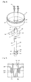
FIG. 3 is an exploded perspective view of an accumulator frame and the stationary shaft in the compressor ofFIG. 1 ; -
FIG. 4 is a cross-sectional view illustrating an embodiment in which a bearing member is provided between a lower frame and a lower bearing in the compressor ofFIG. 1 ; -
FIG. 5 is a cross-sectional view taken along line I-I ofFIG. 1 ; -
FIG. 6 is a cross-sectional view of a fixing structure of the stationary shaft of the compressor ofFIG. 1 ; -
FIG. 7 is a plan view of an eccentric portion of the stationary shaft of the compressor ofFIG. 1 ; -
FIG. 8 is a cross-sectional view of the compression device in the compressor ofFIG. 1 ; -
FIG. 9 is a cross-sectional view taken along line II-II ofFIG. 8 ; -
FIG. 10 is a cross-sectional view of a coupling between a cylinder and a rotor of the compressor ofFIG. 1 , according to another embodiment; -
FIG. 11 is a perspective view of the compression device of the compressor ofFIG. 1 ; -
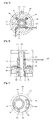
FIG. 12 is a cross-sectional view of a compressor according to another embodiment; -
FIG. 13 is an enlarged cross-sectional view of a stator fixing structure of the compressor ofFIG. 12 ; -
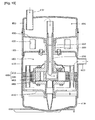
FIG. 14 is a cross-sectional view of a compressor according to another embodiment; -
FIG. 15 is a cross-sectional view of an assembly structure of a stationary bush that controls concentricity to a stationary shaft in the compressor ofFIG. 14 ; -
FIG. 16 is a cross-sectional view of an assembly position of a terminal in the compressor ofFIG. 14 ; -
FIG. 17 is a cross-sectional view of a compressor according to still another embodiment; and -
FIG. 18 is a cross-sectional view of a compressor according to still another embodiment. - Hereinafter, a compressor according to embodiments will be described in detail with reference to the accompanying drawings. Where possible, like reference numerals have been used to indicate like elements.
- In general, a compressor, which may be referred to as a hermetic compressor, may be provided with a drive motor that generates a driving force installed in an internal space of a sealed shell and a compression unit or device operated in combination with the drive motor to compress refrigerant. Compressors may be divided into reciprocating compressors, scroll compressors, rotary compressors, and oscillating compressors according to a method of compressing refrigerant. The reciprocating, scroll, and rotary type compressors use a rotational force of the drive motor; however, the oscillating type compressor uses a reciprocating motion of the drive motor.
- In the above-described compressors, a drive motor of the compressor using rotational force may be provided with a crank shaft that transfers the rotational force of the drive motor to the compression device. For instance, the drive motor of the rotary type hermetic compressor (hereinafter, "rotary compressor") may include a stator fixed to the shell, a rotor inserted into the stator with a predetermined gap therebetween and rotated in accordance with an interaction with the stator, and a crank shaft coupled with the rotor to transfer the rotational force of the drive motor to the compression device while being rotated together with the rotator. In addition, the compression device may include a cylinder that forms a compression space, a vane that divides the compression space of the cylinder into a suction chamber and a discharge chamber, and a plurality of bearing members that forms a compression space together with the cylinder while supporting the vane. The plurality of bearing members may be disposed at one side of the drive motor or disposed at both sides thereof, respectively, to provide support in both axial and radial directions, such that the crank shaft may be rotated with respect to the cylinder.
- Further, an accumulator, which may be connected to a suction port of the cylinder to divide refrigerant inhaled into the suction port into gas refrigerant and liquid refrigerant and inhale only the gas refrigerant into a compression space, may be installed at a side of the shell. The capacity of the accumulator may be determined according to a capacity of the compressor or cooling system. Further, the accumulator may be fixed by, for example, a band or a clamp at an outer portion of the shell, and may communicate with a suction port of the cylinder through a L-shaped suction pipe, which may be fixed to the shell.
- However, in the case of the above-described rotary compressor, the accumulator may be installed at an outer portion of the shell. Thus, a size of the compressor including the accumulator may be increased, thereby increasing a size of an electrical product employing the compressor.
- Further, in such a rotary compressor, the accumulator may be connected to a separate suction pipe outside of the shell, and thus, the assembly of the shell and accumulator may be separated from each other, complicating an assembly process while increasing a number of assembly processes. Moreover, a number of connecting portions may be increased, as both sides of the accumulator are connected to the shell through refrigerant pipes, respectively, thereby increasing the possibility of refrigerant leakage.
- Furthermore, in such a rotary compressor, an area occupied by the compressor may be increased, because the accumulator is installed outside of the shell, thereby limiting design flexibility when the compressor is mounted, for example, on or to an outdoor device of a cooling cycle apparatus. Also, in such a rotary compressor, the accumulator may be eccentrically disposed with respect to a center of gravity of the entire compressor including the accumulator, and thus, an eccentric load due to the accumulator may occur, as the accumulator is installed outside of the shell, thereby increasing vibration noise of the compressor.
- Also, in such a rotary compressor, the crank shaft may be supported at a side of the drive motor and rotated in a radial direction with respect to the drive motor, thereby increasing vibration generated during rotation of the crank shaft. In addition, a length of a bearing that supports the crank shaft in a radial direction may be lengthened to increase an axial directional length of the entire compressor, or a separate bearing member may be required equal to the reduced length of the bearing when reducing the length of the bearing, thereby increasing the fabrication cost.
- Also, in such a rotary compressor, a drive motor and a compression device installed at an inner portion of the shell may be installed at both sides of the crank shaft, thereby increasing a total height of the compressor. Due to this, the compressor cannot be installed at a center of the outdoor device, but rather, is installed biased to one side, taking into consideration interference with other components when the compressor is mounted, for example, in an outdoor device of a cooling cycle apparatus. Therefore, a center of gravity of the outdoor device may be eccentrically located to a side at which the compressor is installed, thereby causing inconvenience or spatial restrictions when moving or installing the outdoor device as well as aggravating vibration noise of the entire outdoor device.
- As illustrated in
FIGS. 1 through 3 , a compressor, which may be referred to as a hermetic compressor, according to an embodiment may include adrive motor 200 that generates a rotational force installed in aninternal space 101 of a sealedshell 100, which may be hermetically sealed, and astationary shaft 300 fixed in theinternal space 101 of theshell 100 at a center of thedrive motor 200. Thestationary shaft 300 may be rotatably coupled with acylinder 410 coupled with arotor 220 of thedrive motor 200 to be rotated by thestationary shaft 300. Anaccumulator 500 having a predetermined accumulatingchamber 501 may be provided separated within and from theinternal space 101 of theshell 100 and coupled with thestationary shaft 300. - The
shell 100 may include ashell body 110, within which thedrive motor 200 may be installed, anupper cap 120 that forms an upper surface of theaccumulator 500 while covering an upper open end (hereinafter, "first open end") 111 of theshell body 110, and alower cap 130 that covers a lower open end (hereinafter, "second open end") 112 of theshell body 110. Theshell body 110 may be formed in a cylindrical shape. Astator 210, which will be described later, may be fixed to a middle portion of theshell body 110 in, for example, a shrink-fitting manner. Further, alower frame 140 that supports alower bearing 430, which will be described later, in a radial direction, as well as thestator 210 may be fixed to theshell body 110 at a lower portion of thestator 210 by, for example, shrink-filling. Thelower frame 140 may include abearing hole 141, into a center of which thelower bearing 430 may be rotatably inserted to support thestationary shaft 300, which will be described later, in a radial direction. An edge of thelower frame 140 may be bent and formed with a fixing portion that allows an outer circumferential surface thereof to be closely adhered to theshell body 110. An outer front end surface of thelower frame 140, namely, an end of the fixingportion 142, may be closely adhered to a lower surface of thestator 210 and fixed to theshell body 110 to support thestator 210 in an axial direction. - The
lower frame 140 may be made of, for example, a metal plate or a casting. When thelower frame 140 is made of a metal plate, aseparate bearing member 145, such as a ball bearing or bush, may be installed thereon, to provide lubrication between thelower frame 140 and thelower bearing 430, as illustrated inFIG. 4 . However, when thelower frame 140 is made of a casting, abearing hole 141 of thelower frame 140 may be precision processed, and therefore, a separate bearing member may not be required. When theseparate bearing member 145 is installed between thelower frame 140 and thelower bearing 430, abearing support portion 143 may be bent and formed to support the bearingmember 145 at an end of thebearing hole 141 of thelower frame 140, as illustrated inFIG. 4 . - An
accumulator frame 150, which may form a lower surface of theaccumulator 500, may be provided at an upper end of theshell body 110. Theaccumulator frame 150 may include abush hole 151, through a center of which a stationary bush (upper bush) 160, which will be described later, may penetrate and be coupled therewith. As illustrated inFIG. 5 , an inner diameter of thebush hole 151 may be larger than an outer diameter of theshaft receiving portion 161 of thestationary bush 160, which will be described later, by a clearance (t1), which may be advantageous during a process of centering thestationary shaft 300, which will be described later. - Further, a one or more through hole(s) 152 configured to fasten the
accumulator frame 150 and thestationary bush 160 by, for example, abolt 155 may be formed at a periphery of thebush hole 151, as illustrated inFIG. 5 . A diameter of the one or more through hole(s) 152 may be larger than a diameter of, for example, thebolt 155 or a diameter of one or more fastening hole(s) 166 provided in thestationary bush 160 by a clearance (t2), which may be advantageous during the process of centering thestationary shaft 300. - An edge of the
accumulator frame 150 may be formed with a fixingportion 153 that extends in a radial direction a length to overlap with theshell body 110 and an end of theupper cap 120. The fixingportion 153 of theaccumulator frame 150 may be closely adhered to an inner circumferential surface of theshell body 110 and an inner circumferential surface of theupper cap 120. The fixingportion 153 may be, for example, coupled to theshell body 110 and the end of theupper cap 120 so that theshell body 110, theupper cap 120, and theaccumulator frame 150 are joined together, thereby enhancing a sealability of theshell 100. The fixingprotrusion 153 may be interposed between theshell body 110 and the end of theupper cap 120, as shown inFig. 1 . - The
stationary bush 160 may include theshaft receiving portion 161, which may be inserted into thebush hole 151 of theaccumulator frame 150, and aflange portion 165 that extends in a radial direction at a middle portion of a circumferential surface of theshaft receiving portion 161. Theshaft receiving portion 161 may include ashaft receiving hole 162, through a center of which thestationary shaft 300 may penetrate. A sealingmember 167 that provides a seal between the accumulatingchamber 501 of theaccumulator 500 and theinternal space 101 of theshell 100 may be provided at the middle portion of theshaft receiving portion 161. Further, as illustrated inFIGS. 5 and 6 , apin fixing hole 163 may be formed at an upper end side of theshaft receiving portion 161 configured to receive a fixingpin 168 that fastens thestationary shaft 300 within theshaft receiving hole 162. Thestationary bush 160 and thestationary shaft 300 may be fixed using other approximate means, such as a fixing bolt or a fixing ring, other than the above-discussedfixing pin 168. Anoil drain hole 164 that collects oil separated from theaccumulator 500 into acompression space 401 through arefrigerant suction passage 301 of thestationary shaft 300 may also be formed at the middle portion of theshaft receiving portion 161, namely, at a portion adjacent to theflange portion 165. - The
flange portion 165 may be formed such that a radial directional width thereof is larger than a radial directional width of theshaft receiving portion 161, thereby allowing a clearance when thestationary bush 160 performs a centering operation together with thestationary shaft 300. One or more of the fastening hole(s) 166 may be formed at or in theflange portion 165 to correspond to the one or more through hole(s) 152 of theaccumulator frame 150. A diameter of the fastening hole(s) 166 may be smaller than a diameter of the through hole(s) 152. - An edge of the
upper cap 120 may be bent to face a firstopen end 111 of theshell body 110, and may be, for example, welded thereto together with the fixingportion 153 of theaccumulator frame 150. Further, asuction pipe 102 that guides refrigerant to theaccumulator 500 during a cooling cycle may penetrate and be coupled with theupper cap 120. Thesuction pipe 102 may be eccentrically disposed to one side of theupper cap 120, so as not to concentrically correspond to therefrigerant suction passage 301 of thestationary shaft 300, which will be described later, thereby preventing liquid refrigerant from being inhaled into thecompression space 401. Furthermore, adischarge pipe 103 that guides refrigerant discharged into theinternal space 101 of theshell 100 from thecompression device 400 may penetrate and be coupled with theshell body 110 between thestator 210 and theaccumulator frame 150. An edge of thelower cap 130 may be attached, for example, by welding to a second open end 112 of theshell body 110. - As illustrated in
FIG. 1 , thedrive motor 200 may include astator 210 fixed to theshell 100 and arotor 220 rotatably disposed at an inner portion of thestator 210. - The
stator 210 may include a plurality of ring-shaped stator sheets laminated together to a predetermined height, and a coil 230 wound around a teeth portion provided at an inner circumferential surface thereof. Further, thestator 210 may be, for example, shrink-fitted to be fixed and coupled with theshell body 110 in an integrated manner. A front end surface of thelower frame 140 may be closely adhered and fixed to a lower surface of thestator 210. - An
oil collecting hole 211 may be formed adjacent to and penetrate an edge of thestator 210 to pass oil collected in theinternal space 101 of theshell 100 through thestator 210 into thelower cap 130. Theoil collecting hole 211 of thestator 210 may communicate with anoil collecting hole 146 of thelower frame 140. - The
rotor 220, which may include amagnet 212, may be disposed at an inner circumferential surface of thestator 210 with a predetermined gap therebetween and may be coupled with thecylinder 410, which will be described later, at a center thereof. Therotor 220 andcylinder 410 may be coupled with an upper bearing plate (hereinafter, abbreviated as an "upper bearing") 420 and/or the lower bearing plate (hereinafter, abbreviated as a "lower bearing") 430, which will be described later, by, for example, a bolt. Therotor 220 andcylinder 410 may be molded in an integrated manner using, for example, a sintering process. - As illustrated in
FIGS. 1 through 3 , thestationary shaft 300 may include ashaft portion 310 having a predetermined length in an axial direction, both ends of which may be fixed to theshell 100, and aneccentric portion 320 that extends eccentrically at a middle portion of theshaft portion 310 in a radial direction and which is accommodated in thecompression space 401 of thecylinder 410 to vary a volume of thecompression space 401. Theshaft portion 310 may be formed such that a center of thestationary shaft 300 corresponds to a rotational center of thecylinder 410 or a rotational center of therotor 220 or a radial center of thestator 210 or a radial center of theshell 100, whereas theeccentric portion 320 may be formed such that the center of thestationary shaft 300 is eccentrically located with respect to the rotational center of thecylinder 410 or the rotational center of therotor 220 or the radial center of thestator 210 or the radial center of theshell 100. - An upper end of the
shaft portion 310 may be inserted into the accumulatingchamber 501 of theaccumulator 500, whereas a lower end of theshaft portion 310 may penetrate in an axial direction and be rotatably coupled with theupper bearing 420 and thelower bearing 430 to support the same in a radial direction. - A first
suction guide hole 311, an upper end of which may communicate with the accumulatingchamber 501 of theaccumulator 500 to form therefrigerant suction passage 301, may be formed at an inner portion of theshaft portion 310 and having a predetermined depth in an axial direction, so as to extend nearly to a lower end of theeccentric portion 320, and a secondsuction guide hole 321, an end of which may communicate with the firstsuction guide hole 311 and the other end of which may communicate with thecompression space 401, to form therefrigerant suction passage 301 together with the firstsuction guide hole 311, may penetrate theeccentric portion 320 in a radial direction. - As illustrated in
FIG. 6 , apin hole 312 may penetrate an upper side portion of theshaft portion 310, in particular, at a position corresponding to thepin fixing hole 163 of thestationary bush 160, in a radial direction to allow the fixingpin 168 to pass therethrough, and anoil drain hole 313 that collects oil in theaccumulator 500 may be formed at a lower side of thepin hole 312, for example, at a height lower than a height of thebush hole 151 and a bottom surface of theaccumulator frame 150, to communicate with the firstsuction guide hole 311. - The
eccentric portion 320 may be formed in a disc shape having a predetermined thickness, as illustrated inFIG. 7 , and thus, may be eccentrically formed with respect to a center of theshaft portion 310 in a radial direction. An eccentric amount of theeccentric portion 320 may be sufficiently large according to a capacity of the compressor, as theshaft portion 310 is fixed to and coupled with theshell 100. - The second
suction guide hole 321, which may form therefrigerant suction passage 301 together with the firstsuction guide hole 311, may penetrate an inner portion of theeccentric portion 320 in a radial direction. A plurality of second suction guide holes 321 may be formed in a straight line, as shown inFIG. 7 ; however, according to other circumstances, for example, the secondsuction guide hole 321 may penetrate and be formed in only one direction with respect to the firstsuction guide hole 311. - A
suction guide groove 322 may be formed, for example, in a ring shape, at an outer circumferential surface of theeccentric portion 320 to communicate refrigerant at all times with asuction port 443 of theroller vane 440, which will be described later, through the secondsuction guide hole 321. Alternatively,suction guide groove 322 may also be formed at an inner circumferential surface of theroller vane 440, or may be formed at both an inner circumferential surface of theroller vane 440 and an outer circumferential surface of theeccentric portion 320. Further, thesuction guide groove 322 may not necessarily be in a ring shape, but rather, may also be formed in a long circular arc shape in a circumferential direction, for example. Other shapes of thesuction guide groove 322 may also be appropriate. - The
compression device 400 may be coupled with theeccentric portion 320 of thestationary shaft 300 to compress refrigerant while being rotated together with therotor 220. As illustrated inFIGS. 8 and 9 , thecompression device 400 may include thecylinder 410, theupper bearing 420 and thelower bearing 430 positioned at both sides of thecylinder 410, respectively, to form thecompression space 401, and theroller vane 440 provided between thecylinder 410 and theeccentric portion 320 to compress refrigerant while varying thecompression space 401. - The
cylinder 410 may be formed in a ring shape to form thecompression space 401 therewithin. A rotational center of thecylinder 410 may be provided to correspond to an axial center of thestationary shaft 300. Further, avane slot 411, into which theroller vane 440 may be slidably inserted in a radial direction while being rotated, may be formed at a side of thecylinder 410. Thevane slot 411 may be formed in various shapes according to the shape of the roller vane. For example, arotation bush 415 may be provided in thevane slot 411, such that avane portion 442 of theroller vane 440 may be rotationally moved in thevane slot 411, when aroller portion 441 and thevane portion 442 of theroller vane 440 are formed in an integrated manner, as illustrated inFIG. 9 . Further, thevane slot 411 may be formed in a slide groove shape, such that thevane portion 442 may be slidably moved in thevane slot 411 when theroller portion 441 andvane portion 442 are rotatably coupled with each other. - An outer circumferential surface of the
cylinder 410 may be inserted into therotor 220 and coupled therewith in an integrated manner. For example, thecylinder 410 may be pressed to therotor 220 or fastened to theupper bearing 420 or thelower bearing 430 using, for example,fastening bolts 402, 403. - When the
cylinder 410 andupper bearing 420 are fastened by or to thelower bearing 430, an outer diameter of thelower bearing 430 may be formed larger than that of thecylinder 410, whereas an outer diameter of theupper bearing 420 may be formed to be approximately similar than that of thecylinder 410. Further, a first throughhole 437 configured to fasten thecylinder 410 and a second throughhole 438 configured to fasten therotor 220 may be formed, respectively, on thelower bearing 430. The first throughhole 437 and second throughhole 438 may be formed on radially different lines to enhance a fastening force, but may be also formed on the same line based on assembly considerations. A fastening bolt 402 may pass through thelower bearing 430 and be fastened to thecylinder 410 and afastening bolt 403 may pass through the upper bearing 420 (via first through hole 427) and be fastened to thecylinder 410. Thefastening bolts 402 and 403 may be formed to have the same fastening depth. - The
cylinder 410 may be molded together with therotor 220 in an integrated manner, as illustrated inFIG. 10 . For example, thecylinder 410 androtor 220 may be molded in an integrated manner through, for example, a powder metallurgy or die casting process. In this case, thecylinder 410 androtor 220 may be formed using the same material, or different materials. When thecylinder 410 androtor 220 are formed using different materials, thecylinder 410 may be formed of a material having a relatively high abrasion resistance in comparison to therotor 220. Further, when thecylinder 410 androtor 220 are formed in an integrated manner, theupper bearing 420 and thelower bearing 430 may be formed to have the same or a smaller outer diameter than that of thecylinder 410, as illustrated inFIG. 10 . - As illustrated in
FIG 9 , aprotrusion portion 412 and agroove portion 221 may be formed at an outer circumferential surface of thecylinder 410 and an inner circumferential surface of therotor 220, respectively, to enhance a combining force between thecylinder 410 and therotor 220, as illustrated inFIG. 9 . Thevane slot 411 may be formed within a range of a circumferential angle formed by theprotrusion portion 412 of thecylinder 410. A plurality of protrusion portions and groove portions may be provided. When a plurality of protrusion portions and groove portions are provided, they may be formed at a same interval along the circumferential direction to cancel out magnetic unbalance. - As illustrated in
FIG. 11 , theupper bearing 420 may be formed such that ashaft receiving portion 422 that supports theshaft portion 310 of thestationary shaft 300 in a radial direction protrudes upward a predetermined height at a center of an upper surface of thestationary plate portion 421. Therotor 220, thecylinder 410, and a rotating body including theupper bearing 420 and thelower bearing 430, which will be described later, may have a rotational center corresponding to an axial center of thestationary shaft 300. Thus, the rotating body may be efficiently supported even though theshaft receiving portion 422 of theupper bearing 420 or theshaft receiving portion 432 of thelower bearing 430 do not have a long length. - The
stationary plate portion 421 may be formed in a disc shape and may be fixed to an upper surface of thecylinder 410. Ashaft receiving hole 423 of theshaft receiving portion 422 may be formed to be rotatably coupled with thestationary shaft 300. Anoil groove 424, which will be described later, may be formed in, for example, a spiral shape at an inner circumferential surface of theshaft receiving hole 423. - A
discharge port 425 may be formed at a side of theshaft receiving portion 422 to communicate with thecompression space 401, and adischarge valve 426 may be formed at an outlet end of thedischarge port 425. Amuffler 450 that reduces discharge noise of refrigerant being discharged through thedischarge port 425 may be coupled with an upper side of theupper bearing 420. - As illustrated in
FIGS. 8 and11 , thelower bearing 430 may be formed to be symmetrical to theupper bearing 420, such that ashaft receiving portion 432 that supports theshaft portion 310 of thestationary shaft 300 in a radial direction protrudes downward a predetermined height at a center of a lower surface of thestationary plate portion 431. Therotor 220, thecylinder 410, and the rotating body including theupper bearing 420 and thelower bearing 430 may have a rotational center corresponding to an axial center of thestationary shaft 300, and thus, the rotating body may be efficiently supported even though theshaft receiving portion 432 of thelower bearing 430 does not have as long a length as theshaft receiving portion 422 of theupper bearing 420. - The
stationary plate portion 431, which may be formed in a disc shape, may be fixed to a lower surface of thecylinder 410, and ashaft receiving hole 433 of theshaft receiving portion 432 may be formed to be rotatably coupled with thestationary shaft 300. Anoil groove 434, which will be described later, may be formed in a spiral shape at an inner circumferential surface of theshaft receiving hole 433. - When the
cylinder 410 androtor 220 are separately formed, therotor 220 and thecylinder 410 may be coupled with each other by means of astationary plate portion 431 of thelower bearing 430. Of course, thecylinder 410 androtor 220 may be coupled in an integrated manner by means of theupper bearing 420. - The
accumulator 500 may be formed separated within and from theinternal space 101 of theshell 100, as theaccumulator frame 150 is sealed and coupled with an inner circumferential surface of theshell body 110, as described above. For theaccumulator frame 150, an edge of a circular plate body may be bent and an outer circumferential surface thereof attached to, for example, welded and coupled with a joint portion between theshell body 110 and theupper cap 120, while being closely adhered to an inner circumferential surface of theshell body 110 and an inner circumferential surface of theupper cap 120, to seal the accumulatingchamber 501 of theaccumulator 500. - A compressor having the foregoing configuration according to embodiments may be operated as follows.
- When the
rotor 220 is rotated by applying power to thestator 210 of thedrive motor 200, thecylinder 410 coupled with therotor 220 through theupper bearing 420 or thelower bearing 430 may be rotated with respect to thestationary shaft 300. Then, theroller vane 440 slidably coupled with thecylinder 410 may generate a suction force as it divides thecompression space 401 of thecylinder 410 into a suction chamber and a discharge chamber. - Then, refrigerant may be inhaled into the accumulating
chamber 501 of theaccumulator 500 through thesuction pipe 102, and the refrigerant divided into gas refrigerant and liquid refrigerant in the accumulatingchamber 501 of theaccumulator 500. The gas refrigerant may be inhaled into the suction chamber of thecompression space 401 through the firstsuction guide hole 311 and secondsuction guide hole 321 of thestationary shaft 300, thesuction guide groove 322, and thesuction port 443 of theroller vane 440. The refrigerant inhaled into the suction chamber may be compressed while being moved to the discharge chamber by theroller vane 440 as thecylinder 410 continues to be rotated, and discharged to theinternal space 101 of theshell 100 through thedischarge port 425. The refrigerant discharged to theinternal space 101 of theshell 100 may repeat a series of processes before being discharged to a cooling cycle apparatus through thedischarge pipe 103. At this time, oil in thelower cap 130 may be pumped byoil feeder 460 provided at a lower end of thelower bearing 430, while thelower bearing 430 is rotated at high speed together with therotor 220, and passed sequentially through theoil groove 434 of thelower bearing 430, thebottom oil pocket 323, the oil through hole(s) 325, thetop oil pocket 324, theoil groove 424 of theupper bearing 420, to be supplied to each sliding surface. - Hereinafter, an assembly sequence of a compressor according to embodiments will be described.
- In a state that the
stator 210 and thelower frame 140 of thedrive motor 200 are fixed to theshell body 110 in, for example, a shrink-fitting manner, thestationary shaft 300 may be inserted into thestationary bush 160 to be fixed by means of, for example, the fixingpin 168. Therotor 220, thecylinder 410, and both thebearings stationary shaft 300. - Next, in a state of maintaining a concentricity of the
stator 210 and therotor 220, theaccumulator frame 150 may be inserted into theshell body 110 to fasten thestationary bush 160 to theaccumulator frame 150, and theaccumulator frame 150 may be, for example, three-point welded to theshell body 110 for a temporary fix. Then, thelower cap 130 may be pressed to the second open end 112 of theshell body 110, and a joint portion between thelower cap 130 and theshell body 110 may be, for example, circumferentially welded to be sealed. - Next, the
upper cap 120 may be, for example, pressed to the upperopen end 111 of theshell body 110, and a joint portion between theupper cap 120 and theshell body 110 may be, for example, circumferentially welded together with theaccumulator frame 150 to seal theinternal space 101 of theshell 100, while forming the accumulatingchamber 501 of theaccumulator 500. - As described above, a portion of the internal space of the shell may be used for the accumulator, which may be installed separated within and from the internal space of the shell, thereby reducing a size of the compressor including the accumulator.
- Further, an assembly process of the accumulator and an assembly process of the shell may be unified to simplify an assembly process of the compressor. Further, an accumulating chamber of the accumulator may be directly connected to a refrigerant suction passage of the stationary shaft by coupling the stationary shaft with the accumulator to prevent leakage of refrigerant from occurring, thereby enhancing compressor performance. Furthermore, an area required for installing the compressor may be minimized when installing the compressor including the accumulator in an outdoor device, thereby enhancing design flexibility of the outdoor device. A center of gravity of the accumulator may be placed at a location corresponding to that of the entire compressor including the accumulator, thereby reducing vibration noise of the compressor due to the accumulator. Also, an eccentric portion for forming a compression space in the stationary shaft may be provided, while an axial center of the stationary shaft corresponds to a rotational center of the cylinder, thereby securing a spacious compression space and increasing compressor capacity.
- Further, the stator and lower frame may be, for example, shrink-fitted at the same time to be fixed to the shell, thereby preventing the shell from being thermally deformed in a non-uniform manner while the concentricity of the stator is distorted, as well as allowing the lower frame to support a bottom surface of the stator to more securely fix the stator. Both ends of the stationary shaft may be supported by a frame fixed to the shell in a radial direction, thereby effectively suppressing movement of the stationary shaft due to vibration generated during rotation of the rotational body, as well as enhancing durability and reliability of the compressor, although a separate bearing is not installed between the stationary shaft and rotational body or the bearing is used to the minimum.
- Interference with other components due to the compressor may be minimized to allow the compressor having a weight relatively higher than that of other components to be installed at the center of gravity of an outdoor device, thereby facilitating movement and installation of the outdoor device.
- Another embodiment of an accumulator in a compressor will be described hereinbelow.
- According to the foregoing embodiment, the
stator 210 and theaccumulator frame 150 may be fixed in, for example, a shrink-fitting manner at the same time to an inner circumferential surface of theshell 100; however, according to this embodiment, thestator 1210 may be inserted and fixed to the shell 1100, as illustrated inFIG. 12 . - That is, the shell 1100 may include an upper shell 1110 and a
lower shell 1130, and amiddle shell 1140 located between the upper shell 1110 andlower shell 1130. Thedrive motor 1200 andcompression device 1400 may be installed together in themiddle shell 1140, and the drivingshaft 1300 may penetrate and be coupled with themiddle shell 1140. - The upper shell 1110 may be formed in a cylindrical shape, and a lower end thereof may be coupled with an
upper frame 1141 of themiddle shell 1140, which will be described later, whereas an upper end thereof may be coupled with anupper cap 1120. Further, asuction pipe 1102 may be coupled with the upper shell 1110, and anaccumulator frame 1150 may be coupled with an inner circumferential surface of the upper shell 1110 to form an accumulatingchamber 1501 of theaccumulator 1500 together with theupper cap 1120. - A
bush hole 1151 may be formed at a center of theaccumulator frame 1150. A sealingbush 1510 may be provided between an inner circumferential surface of thebush hole 1151 and an outer circumferential surface of thestationary shaft 1300. A sealingmember 1551 may be inserted into an inner circumferential surface of the sealingbush 1510 to seal the accumulatingchamber 1501 of theaccumulator 1500. - The
bush hole 1151 may protrude and extend downward in the form of a burr. Further, an upper end of thestationary shaft 1300 may be positioned adjacent to an upper surface of theaccumulator frame 1150. A separate extension pipe 1310 may be connected to an upper end of thestationary shaft 1300. The separate extension pipe 1310 may have an inner diameter greater than that of the stationary shaft 1300 (i.e., an inner diameter of the refrigerant suction passage) to reduce suction loss. - The
lower shell 1130 may be formed in, for example, a cup shape, such that an upper end thereof is open and a lower end thereof closed. The open upper end may be coupled with alower frame 1145, which will be described later. - The
middle shell 1140 may be divided into anupper frame 1141 and alower frame 1145 with respect to thestator 1210 of thedrive motor 1200. Further, as illustrated inFIG. 13 ,grooves upper frame 1141 and a top end of thelower frame 1145, respectively, that face each other, which allow lateral surfaces of thestator 1210 to be inserted and supported thereby. Furthermore, acommunication hole 1333 that guides refrigerant discharged from thecompression device 1400 may be formed on theupper frame 1141, and anoil hole 1337 that collects oil may be formed on thelower frame 1145. - The other basic configuration and working effects thereof in the compressor according to this embodiment as described above may be substantially the same as the foregoing embodiment. However, according to this embodiment, the
stator 1210 may be inserted and fixed between theupper frame 1141 and thelower frame 1145 forming part of the shell, and thus, easily assembled based on a concentricity between thestator 1210 and drivingshaft 1300. In other words, according to this embodiment, thestator 1210 may be mounted on thegroove 1146 of thelower frame 1145, then the drivingshaft 1300 coupled with therotor 1220 and thecylinder 1410 inserted into thestator 1210, and theupper frame 1141 inserted onto thestationary shaft 1300 to support an upper surface of thestator 1210 via thegroove 1142 of theupper frame 1141. Theupper frame 1141 andlower frame 1145 may be attached, for example, welded, and coupled with each other, and the upper shell 1110 coupled with theaccumulator frame 1150 may be inserted onto theupper frame 1141, which may be attached, for example, welded to the upper shell 1110. At this time, prior to attaching theupper frame 1141 to thelower frame 1145, a gap maintaining member, such as a gap gauge, may be inserted between thestator 1210 and therotor 1220, and then the upper shell 1110 may be adjusted in a radial direction. As a result, thestationary shaft 1300 may maintain a concentricity with respect to thestator 1210. Accordingly, components may be easily assembled based on a concentricity of the stationary shaft when compared to the method of fastening and fixing the stationary bush to the accumulator frame while adjusting the stationary bush in a radial direction in a state in which the gap maintaining member is inserted between the stator and rotor, as described. - According to this embodiment, the
stationary shaft 1300 may be supported in an axial direction with respect to theupper frame 1141 using astationary member 1168, such as a fixing pin, a fixing bolt, or a fixing ring, that passes through theupper frame 1141 andstationary shaft 1300. However, thestationary shaft 1300 may be supported in an axial direction by supporting a lower end of thebush hole 1151 of theaccumulator frame 1150 with theupper frame 1141. In this case, the sealingbush 1510 may be, for example, pressed and fixed to thebush hole 1151 of theaccumulator frame 1150, and thestationary shaft 1300 may be pressed to the sealingbush 1510 or fixed by using another stationary member. - Still another embodiment of a compressor will be described hereinbelow.
- According to the foregoing embodiment, the accumulator includes an accumulating chamber which uses a portion of the shell, namely, an upper cap, but according to this embodiment, the accumulator may be formed to have a separate accumulating chamber in the internal space of the shell and coupled with an inner circumferential surface of the shell to be separated by a predetermined distance.
- As illustrated in
FIG. 14 , according to this embodiment, thedrive motor 2200 andcompression device 2400 may be installed in theshell body 2110, a lower end of which may be open to form part of theshell 2100. A lower end of theshell body 2110 may be sealed bylower cap 2130. Atop shell 2120 may be coupled with an upper end of theshell body 2110, and acommunication hole 2112 may be formed at an upper surface of theshell body 2110, such that aninternal space 2111 of theshell body 2110 may communicate with aninternal space 2121 of thetop shell 2120. Further, thestationary shaft 2300 may be inserted into a center of theshell body 2110 to fasten thestationary bush 2160 by means of, for example, afixing pin 2168. Theaccumulator 2500 separated by a predetermined distance to have a separate accumulatingchamber 2501 in the internal space of thetop shell 2120 may be coupled with an upper end of thestationary shaft 2300. Theaccumulator 2500 may be fixed to the shell by means of asuction pipe 2102 that passes through thetop shell 2120 and is coupled therewith. - As illustrated in
FIG. 15 , thebush hole 2113 may be formed at or in theshell body 2110 to pass through theshaft receiving portion 2161 of thestationary bush 2160, and the throughhole 2114 configured to fasten thestationary bush 2160 with thebolt 2115 may be formed adjacent to thebush hole 2113. Further, afastening hole 2166 may be formed at aflange portion 2165 of thestationary bush 2160 to correspond to the throughhole 2114. - An inner diameter of the
bush hole 2113 may be larger than that of theshaft receiving portion 2161, while a diameter of the throughhole 2114 may larger than that of thefastening hole 2166, thereby facilitating assembly based on a concentricity of thestationary shaft 2300. Further, thestator 2210 of thedrive motor 2200 may be, for example, shrink-fitted and fixed to theshell body 2110, and thelower frame 2140, which supports a lower end of thestationary shaft 2300 while at the same time supporting thestator 2210, may be, for example, shrink-fitted and fixed to a lower end of thestator 2210. Adischarge pipe 2103 that communicates with theinternal space 2121 of thetop shell 2120 to discharge compressed refrigerant to a cooling cycle apparatus may be coupled with a surface through which thesuction pipe 2102 penetrate. - The
accumulator 2500 may be coupled with theupper housing 2510 and thelower housing 2520 to be sealed to each other to form an accumulatingchamber 2501, which may be separated from theinternal space 2121 of thetop shell 2120. A bush hole 2521 may be formed at a center of thelower housing 2520, and a sealingbush 2530 inserted into thestationary shaft 2300 may be fixed to the bush hole 2521. - A
terminal mounting portion 2522 may be formed in a depressed manner, such that a terminal 2104 may be coupled with a side wall surface of thetop shell 2120. The terminal 2104 may be installed at an upper surface of thetop shell 2120, according to circumstances, as illustrated inFIG. 16 . In this case, a separate terminal mounting portion may not be necessarily formed at a side wall surface of theaccumulator 2500, and the sealingbush 2130 may be disposed to be accommodated into the accumulatingchamber 2501 of theaccumulator 2500, thereby preventing a height of the compressor from being increased due to theterminal 2104. - The other basic configuration and working effects thereof in a compressor according to this embodiment as described above may be substantially the same as the foregoing embodiment. However, according to this embodiment, as the
accumulator 2500 is separated from theshell 2100, heat transferred through theshell 2100 may be prevented from being directly transferred to a suction refrigerant, and vibration due to a pulsating pressure generated when absorbing refrigerant may be prevented from being transferred to the shell. - In addition, the
rotor 2220 andcylinder 2410 including thestationary shaft 2300 may be located at an inner portion of thestator 2210 and thestationary bush 2160 fastened to theshell body 2110 based on a concentricity of thestationary shaft 2300, thereby facilitating assembly based on a concentricity between thestationary shaft 2300 andstator 2210. Moreover, thesuction pipe 2102, thedischarge pipe 2103, and the terminal 2104 may be disposed on the same plane, thereby further reducing an area occupied by the compressor and further enhancing the design flexibility of the outdoor device. - Still another embodiment of a compressor will be described hereinbelow.
- In other words, according to the foregoing embodiment, the accumulator may be installed to form an internal volume using a portion of the shell at an inner portion of the shell or may be separated from an inner circumferential surface of the shell by a predetermined distance to separately form an internal volume, but according to this embodiment, the accumulator may be installed to form an internal volume using the shell at an outer portion of the shell.
- As illustrated in
FIG. 17 , according to this embodiment, thedrive motor 3200 andcompression device 3400 may be installed in theshell body 3110, a lower end of which may be open to form part of theshell 3100, and a lower end of theshell body 3110 may be sealed by thelower cap 3130. Further, anaccumulator shell 3510 may be coupled with an upper end of theshell body 3110 to form the accumulator 3500, and an upper surface of theshell body 3110 may be formed in a sealed shape to separate theinternal space 3111 of theshell body 3110 from the accumulatingchamber 3501 of theaccumulator shell 3510. Astationary bush 3160 inserted and fixed by thestationary shaft 3300 may be fastened to a center of theshell body 3110, and thestationary shaft 3300 may be supported in an axial direction by, for example, afixing pin 3168 that passes through thestationary shaft 3300 and thestationary bush 3160 in a radial direction. - Further, a
suction pipe 3102 may communicate and be coupled with an upper surface of theaccumulator shell 3510, and adischarge pipe 3103 that discharges refrigerant discharged from the compression space of thecompression device 3400 to a cooling cycle apparatus may communicate and be coupled with a radial directional surface of theshell body 3110. - The
stator 3210 of thedrive motor 3200 may be, for example, shrink-fitted and fixed to theshell body 3110, and thelower frame 3140, which supports a lower end of thestationary shaft 3300 while at the same time supporting thestator 3210, may be, for example, shrink-fitted and fixed to a lower end of thestator 3210. - The other basic configuration and working effects thereof in a compressor according to this embodiment as described above may be substantially the same as the foregoing embodiment. However, according to this embodiment, the
accumulator shell 3510 forming the accumulator 3500 may be coupled with an outer surface of theshell body 3110 forming the shell to facilitate the assembly of the accumulator, and moreover, therotor 3220 andcylinder 3410 including thestationary shaft 3300 may be located at an inner portion of thestator 3210, and then, thestationary bush 3160 may be fastened to theshell body 3110 based on an concentricity of thestationary shaft 3300 to facilitate the assembly based on a concentricity between thestationary shaft 3300 andstator 3210. - In addition, a thickness of the
accumulator shell 3510 forming the accumulator 3500 may be formed less than that of theshell body 3110 and thelower cap 3130, and a height of theshell 3100 having a relatively higher thickness may be decreased to reduce a weight of the entire compressor. Further, as the accumulator 3500 is installed at an outer portion of theshell 3100, refrigerant inhaled into the accumulatingchamber 3501 of the accumulator 3500 may be quickly dissipated, thereby reducing a specific volume of the inhaled refrigerant and enhancing compressor performance. - Still another embodiment of a compressor will be described hereinbelow.
- In other words, according to the foregoing embodiment of
FIG. 17 , the accumulator may be formed at an outer portion of the shell using an outer surface of the shell to form an accumulating chamber, but according to this embodiment, the accumulator may be installed to have a predetermined distance at an outer portion of the shell. As illustrated inFIG. 18 , according to this embodiment, thedrive motor 4200 and compression device 4400 may be installed in theshell body 4110, a lower end of which may be open to form part of the shell 4100, and a lower end of theshell body 4110 may be sealed bylower cap 4130. - Further, an accumulator 4500 having a separate accumulating
chamber 4501 may be disposed at an upper side of theshell body 4110 to have a predetermined distance, and an upper end of thestationary shaft 4300 may be coupled with the accumulator 4500. Furthermore, the accumulator 4500 may be coupled with an upper shell 4120, which may be inserted and coupled to an outer circumferential surface of the upper side of theshell body 4110. The upper shell 4120 may be formed in a cylindrical shape, such that both opening ends thereof are coupled with theshell body 4110 and accumulator 4500, respectively, for example, by welding. As an upper end of theshell body 4110 is formed in a closed shape, a plurality of throughholes 4121 may be formed to allow an internal space formed by the upper shell 4120 to communicate with the outside. - Further, a
stationary bush 4160 inserted and fixed by thestationary shaft 4300 may be fastened to a center of theshell body 4110, and thestationary shaft 4300 may be supported by, for example, afixing pin 4168 that passes through thestationary shaft 4300 and thestationary bush 4160 in a radial direction. - The
upper housing 4510 and thelower housing 4520 may be sealed to each other to form an accumulatingchamber 4501 separated from theinternal space 4101 of the shell 4100. Further, asuction pipe 4102 may communicate and be coupled with an upper surface of the accumulator 4500, and adischarge pipe 4103 that discharges refrigerant from the compression space of the compression device 4400 to a cooling cycle apparatus may communicate and be coupled with a radial directional surface of theshell body 4110. Thesuction pipe 4102 may not necessarily communicate with an upper surface of the accumulator 4500, but may also be installed to communicate in parallel with thedischarge pipe 4103. In addition, thedischarge pipe 4103 may not necessarily communicate with a side wall surface of theshell body 4110, but may also communicate with an upper surface of theshell body 4110. - The stator 4210 of the
drive motor 4200 may be, for example, shrink-fitted and fixed to theshell body 4110, and thelower frame 4140, which may support a lower end of thestationary shaft 4300 while at the same time supporting the stator 4210, may be, for example, shrink-fitted and fixed to a lower end of the stator 4210. - The other basic configuration and working effects in a compressor according to the embodiment described above may be substantially the same as the foregoing embodiment. However, according to this embodiment, the accumulator 4500 may be installed to be separated from the shell body 4100 by a predetermined distance, thereby preventing heat generated by the shell body 4100 from being transferred to refrigerant being inhaled into an accumulating chamber of the accumulator 4500, and through this, a specific volume of the refrigerant being inhaled into a compression space of the compression device 4400 may be prevented from being increased, thereby enhancing compressor performance.
- Any reference in this specification to "one embodiment," "an embodiment," "example embodiment," etc., means that a particular feature, structure, or characteristic described in connection with the embodiment is included in at least one embodiment of the invention. The appearances of such phrases in various places in the specification are not necessarily all referring to the same embodiment. Further, when a particular feature, structure, or characteristic is described in connection with any embodiment, it is submitted that it is within the purview of one skilled in the art to effect such feature, structure, or characteristic in connection with other ones of the embodiments.
- Although embodiments have been described with reference to a number of illustrative embodiments thereof, it should be understood that numerous other modifications and embodiments can be devised by those skilled in the art that will fall within the scope of the principles of this disclosure. More particularly, various variations and modifications are possible in the component parts and/or arrangements of the subject combination arrangement within the scope of the disclosure, the drawings and the appended claims. In addition to variations and modifications in the component parts and/or arrangements, alternative uses will also be apparent to those skilled in the art.
Claims (15)
- A compressor, comprising:a shell (100, 1100, 2100, 3100, 4100) having an inner space (101, 2121, 3111, 4101) and a stator (210, 1210, 2210, 3210, 4210) fixed to the shell in the inner space, the inner space of the shell communicating with a discharge pipe (103, 1103, 2103, 3103, 4103);a stationary shaft (300, 1300, 2300, 3300, 4300) configured to support a compression device coupled with a rotor (220, 1220, 2220, 3220, 4220) and having a suction passage (301) communicating with the compression device;an upper support member (150, 1141, 2110, 3110, 4110) provided above the compression device that supports an upper portion of the stationary shaft;a lower support member (140, 1145, 2140, 3140, 4140) provided below the compression device that supports a lower portion of the stationary shaft; the compressor characterised by comprisingan accumulator (500, 1500, 2500, 3500, 4500) coupled to the stationary shaft at an upper side of the upper support member, wherein the stationary shaft is supported in an axial direction by a fixing member (168, 1168, 2168, 3168, 4168) that passes through the stationary shaft and the upper support member in a radial direction,wherein the accumulator forms an accumulating chamber (501,1501,2501,3501,4501) within the inner space of the shell and communicating with the suction passage of the stationary shaft, andwherein the accumulating chamber is separated from the inner space of the shell, and coupled with a suction pipe (102, 1102, 2102, 3102, 4102) that passes through the shell, the accumulating chamber being configured such that refrigerant inhaled into the accumulating chamber through the suction pipe is divided into gas refrigerant and liquid refrigerant in the accumulating chamber, and the gas refrigerant is inhaled through the suction passage into the compression device.
- The compressor of claim 1, wherein an outer circumferential surface of each of the upper support member and the lower support member is fixed to the shell, wherein a bush (160, 1510, 2530) is adjustably coupled to the upper support member in a radial direction, and wherein the stationary shaft is inserted through and coupled to the bush.
- The compressor of claim 1 or 2, wherein the upper support member includes an accumulator frame (150, 1150) that separates the accumulating chamber (501, 1501, 2501, 3111, 4501) from an internal space of the shell.
- The compressor of claim 1 or 2,
wherein the accumulator is coupled with an outer surface of the shell to form the accumulating chamber therewith. - The compressor of claim 1 or 2,
wherein the accumulator is coupled with an inner surface of the shell to form the accumulating chamber therewith. - The compressor of claim 1, wherein a first bush (160, 2160, 3160, 4160) is inserted into the accumulator and coupled thereto, and wherein the stationary shaft is inserted into the first bush in an axial direction.
- The compressor of claim 6, wherein the fixing member is inserted into the first bush and the stationary shaft in a radial direction, such that the stationary shaft is supported by the fixing member in an axial direction with respect to the accumulator.
- The compressor of claim 7, wherein a bush hole (151, 1151, 2113) configured to receive the first bush is formed in the accumulator, and wherein an inner diameter of the bush hole is larger than an outer diameter of the first bush.
- The compressor of claim 8, wherein the first bush comprises a shaft receiving portion (161, 2161) having a shaft receiving hole (162) configured to receive the stationary shaft and a flange portion (165, 2165) that extends in a radial direction from an outer circumferential surface of the shaft receiving portion and which is fixed to the accumulator, and wherein a radial directional width of the flange portion is larger than a radial directional width of the first bush.
- The compressor of claim 9, wherein a fixing hole (163) configured to receive the fixing member (168) is formed in the shaft receiving portion.
- The compressor of any one of claims 6 to 10, wherein the accumulator comprises an accumulator frame fixed to the shell and configured to receive the stationary shaft in an axial direction, and wherein the first bush is supported with respect to the accumulator frame in an axial direction.
- The compressor of any one of claims 6 to 11, further comprising an accumulator frame fixed to the shell, wherein a second bush (1510, 2530) is fixed to the accumulator frame (2110) and configured to receive the stationary shaft (1300, 2300) in an axial direction, and wherein the first bush (2530) is supported with respect to the second bush (2160) in an axial direction.
- The compressor of any one of claims 1 to 12, wherein the stationary shaft is rotatably coupled with one of a plurality of bearings to be supported in a radial direction, and wherein the one of a plurality of bearings is rotatably coupled with a frame fixed to the shell to be supported in a radial direction.
- The compressor of claim 13, further comprising:a bearing member (145) provided between the one of the plurality of bearings (430) and the frame (140).
- The compressor of claim 1, wherein the accumulator is separated from an inner circumferential surface of the shell by a predetermined distance to independently form an accumulating chamber of the accumulator.
Applications Claiming Priority (2)
| Application Number | Priority Date | Filing Date | Title |
|---|---|---|---|
| KR1020100138180A KR101708310B1 (en) | 2010-12-29 | 2010-12-29 | Hermetic compressor |
| PCT/KR2011/010110 WO2012091388A1 (en) | 2010-12-29 | 2011-12-26 | Compressor |
Publications (3)
| Publication Number | Publication Date |
|---|---|
| EP2659145A1 EP2659145A1 (en) | 2013-11-06 |
| EP2659145A4 EP2659145A4 (en) | 2014-10-08 |
| EP2659145B1 true EP2659145B1 (en) | 2015-12-23 |
Family
ID=46380914
Family Applications (1)
| Application Number | Title | Priority Date | Filing Date |
|---|---|---|---|
| EP11853555.8A Not-in-force EP2659145B1 (en) | 2010-12-29 | 2011-12-26 | Compressor |
Country Status (6)
| Country | Link |
|---|---|
| US (1) | US8899947B2 (en) |
| EP (1) | EP2659145B1 (en) |
| KR (1) | KR101708310B1 (en) |
| CN (1) | CN103299080B (en) |
| ES (1) | ES2561283T3 (en) |
| WO (1) | WO2012091388A1 (en) |
Families Citing this family (12)
| Publication number | Priority date | Publication date | Assignee | Title |
|---|---|---|---|---|
| KR101452509B1 (en) * | 2008-07-22 | 2014-10-23 | 엘지전자 주식회사 | Compressor |
| KR101910656B1 (en) * | 2012-04-25 | 2018-10-23 | 삼성전자주식회사 | Hermetic reciprocating compressor |
| TWM472176U (en) * | 2013-11-07 | 2014-02-11 | Jia Huei Microsystem Refrigeration Co Ltd | Rotary compressor improvement |
| CN103953544B (en) | 2014-04-10 | 2016-01-27 | 珠海格力节能环保制冷技术研究中心有限公司 | Compressor and air conditioner |
| CN106837804B (en) * | 2017-01-24 | 2019-06-28 | 广东美芝制冷设备有限公司 | Compressor |
| WO2019032096A1 (en) * | 2017-08-08 | 2019-02-14 | Hitachi-Johnson Controls Air Conditioning, Inc. | Rotary compressor and assembly method thereof |
| JP7216552B2 (en) * | 2019-01-07 | 2023-02-01 | 三菱重工サーマルシステムズ株式会社 | rotary compressor |
| US11841031B2 (en) | 2020-03-13 | 2023-12-12 | Honeywell International Inc. | Compressor sensor mount |
| US11635091B2 (en) | 2020-03-13 | 2023-04-25 | Honeywell International Inc. | Compressor with integrated accumulator |
| CN113550904B (en) * | 2021-08-23 | 2024-04-26 | 广东美芝制冷设备有限公司 | Compressor and air conditioner |
| CN113550907B (en) * | 2021-08-23 | 2023-09-01 | 广东美芝制冷设备有限公司 | Compressor and Refrigeration Equipment |
| CN114876801B (en) * | 2022-06-07 | 2024-03-19 | 广东美芝制冷设备有限公司 | Compressor and temperature regulating device with same |
Family Cites Families (38)
| Publication number | Priority date | Publication date | Assignee | Title |
|---|---|---|---|---|
| US2122462A (en) * | 1936-10-12 | 1938-07-05 | Guy C Fricke | Refrigerant compression unit |
| US2415011A (en) * | 1942-09-18 | 1947-01-28 | Borg Warner | Motor compressor assembly |
| US2420124A (en) | 1944-11-27 | 1947-05-06 | Coulson Charles Chilton | Motor-compressor unit |
| US2440593A (en) * | 1946-10-23 | 1948-04-27 | Harry B Miller | Radial vane pump mechanism |
| US3153334A (en) * | 1963-04-09 | 1964-10-20 | Sperry Rand Corp | Power transmitting mechanism |
| JPS5770984A (en) * | 1980-10-22 | 1982-05-01 | Hitachi Ltd | Closed type scroll compressor |
| JPS60187790A (en) | 1984-03-08 | 1985-09-25 | Mitsubishi Electric Corp | Pressure difference oil supplying device for rolling piston type compressor |
| JPS61187591A (en) | 1985-02-14 | 1986-08-21 | Matsushita Electric Ind Co Ltd | Oil feeder of rotary compressor |
| JPS62284985A (en) | 1986-06-03 | 1987-12-10 | Matsushita Electric Ind Co Ltd | Rotary compressor |
| JPS63186988A (en) | 1987-01-29 | 1988-08-02 | Matsushita Electric Ind Co Ltd | Rotary compressor |
| JPH081182B2 (en) | 1987-02-19 | 1996-01-10 | 株式会社東芝 | 2-cylinder rotary compressor |
| JP2605512B2 (en) | 1991-07-30 | 1997-04-30 | ダイキン工業株式会社 | Compressor and method of manufacturing compressor |
| JP2873888B2 (en) * | 1991-12-27 | 1999-03-24 | 本田技研工業株式会社 | Screw pump rotor |
| US5374171A (en) | 1994-04-11 | 1994-12-20 | Tecumseh Products Company | Rotary compressor thrust washer |
| US5542831A (en) | 1995-05-04 | 1996-08-06 | Carrier Corporation | Twin cylinder rotary compressor |
| KR100186457B1 (en) * | 1996-12-03 | 1999-05-01 | 구자홍 | A rolling piston of a closed type rotary compressor |
| KR100230999B1 (en) | 1997-07-30 | 1999-11-15 | 윤종용 | Structure for disconnecting liquid refrigerant section pipe of rotary compressor comprising |
| KR100240202B1 (en) * | 1997-07-30 | 2000-01-15 | 윤종용 | Rotary compressor comprising accumulator |
| MY119733A (en) | 1997-08-28 | 2005-07-29 | Matsushita Electric Ind Co Ltd | Rotary compressor |
| JPH11182433A (en) * | 1997-12-16 | 1999-07-06 | Sanyo Electric Co Ltd | Enclosed compressor |
| KR19990084586A (en) | 1998-05-08 | 1999-12-06 | 윤종용 | Accumulator of rotary compressors |
| KR100287447B1 (en) | 1998-11-25 | 2001-04-16 | 전주범 | Rotary compressor with accumulator |
| KR20010002267U (en) | 1998-12-08 | 2001-10-23 | 전주범 | Accumulator integrated rotary compressor with insulation |
| JP2000283074A (en) | 1999-03-26 | 2000-10-10 | Mitsubishi Electric Corp | Rotary compressor |
| FR2811383B1 (en) * | 2000-07-07 | 2002-12-13 | Valois Sa | FLUID PRODUCT DISPENSING PUMP |
| JP2002221156A (en) | 2001-01-25 | 2002-08-09 | Mitsubishi Electric Corp | Hermetically enclosed compressor |
| US6592346B2 (en) | 2001-10-16 | 2003-07-15 | Carrier Corporation | Compressor discharge valve |
| JP2004084568A (en) | 2002-08-27 | 2004-03-18 | Sanyo Electric Co Ltd | Multistage compression type rotary compressor and displacement capacity ratio setting method therefor |
| TWI263762B (en) | 2002-08-27 | 2006-10-11 | Sanyo Electric Co | Multi-stage compression type rotary compressor and a setting method of displacement volume ratio for the same |
| US20050031465A1 (en) | 2003-08-07 | 2005-02-10 | Dreiman Nelik I. | Compact rotary compressor |
| WO2005113985A1 (en) * | 2004-05-24 | 2005-12-01 | Daikin Industries, Ltd. | Rotary compressor |
| KR100590494B1 (en) * | 2004-12-14 | 2006-06-19 | 엘지전자 주식회사 | The compressing device for thr orbiter compressor |
| CA2532045C (en) * | 2005-01-18 | 2009-09-01 | Tecumseh Products Company | Rotary compressor having a discharge valve |
| WO2007032337A1 (en) * | 2005-09-12 | 2007-03-22 | Matsushita Electric Industrial Co., Ltd. | Rotary fluid machine and refrigerating cycle device |
| JP4973237B2 (en) | 2006-10-27 | 2012-07-11 | ダイキン工業株式会社 | Rotary fluid machine |
| KR101386481B1 (en) | 2008-03-05 | 2014-04-18 | 엘지전자 주식회사 | Hermetic compressor |
| WO2010010996A2 (en) | 2008-07-22 | 2010-01-28 | Lg Electronics, Inc. | Compressor |
| KR101452509B1 (en) | 2008-07-22 | 2014-10-23 | 엘지전자 주식회사 | Compressor |
-
2010
- 2010-12-29 KR KR1020100138180A patent/KR101708310B1/en active IP Right Grant
-
2011
- 2011-12-26 WO PCT/KR2011/010110 patent/WO2012091388A1/en active Application Filing
- 2011-12-26 EP EP11853555.8A patent/EP2659145B1/en not_active Not-in-force
- 2011-12-26 ES ES11853555.8T patent/ES2561283T3/en active Active
- 2011-12-26 CN CN201180063395.4A patent/CN103299080B/en not_active Expired - Fee Related
- 2011-12-28 US US13/338,737 patent/US8899947B2/en active Active
Also Published As
| Publication number | Publication date |
|---|---|
| KR20120076151A (en) | 2012-07-09 |
| CN103299080A (en) | 2013-09-11 |
| US20120171065A1 (en) | 2012-07-05 |
| US8899947B2 (en) | 2014-12-02 |
| EP2659145A1 (en) | 2013-11-06 |
| KR101708310B1 (en) | 2017-02-20 |
| CN103299080B (en) | 2016-09-14 |
| ES2561283T3 (en) | 2016-02-25 |
| WO2012091388A1 (en) | 2012-07-05 |
| EP2659145A4 (en) | 2014-10-08 |
Similar Documents
| Publication | Publication Date | Title |
|---|---|---|
| EP2659145B1 (en) | Compressor | |
| EP2659143B1 (en) | Compressor | |
| EP2659142B1 (en) | Compressor | |
| US8905734B2 (en) | Compressor | |
| EP2659144B1 (en) | Hermetic compressor and manufacturing method thereof | |
| KR101708307B1 (en) | Hermetic compressor and manufacturing method thereof | |
| KR101708308B1 (en) | Hermetic compressor and manufacturing method thereof | |
| KR101727496B1 (en) | Hermetic compressor | |
| KR101708309B1 (en) | Hermetic compressor | |
| KR101801675B1 (en) | Hermetic compressor | |
| KR101707968B1 (en) | Hermetic compressor | |
| KR101718035B1 (en) | Hermetic compressor | |
| KR20120076163A (en) | Hermetic compressor |
Legal Events
| Date | Code | Title | Description |
|---|---|---|---|
| PUAI | Public reference made under article 153(3) epc to a published international application that has entered the european phase |
Free format text: ORIGINAL CODE: 0009012 |
|
| 17P | Request for examination filed |
Effective date: 20130717 |
|
| AK | Designated contracting states |
Kind code of ref document: A1 Designated state(s): AL AT BE BG CH CY CZ DE DK EE ES FI FR GB GR HR HU IE IS IT LI LT LU LV MC MK MT NL NO PL PT RO RS SE SI SK SM TR |
|
| DAX | Request for extension of the european patent (deleted) | ||
| A4 | Supplementary search report drawn up and despatched |
Effective date: 20140908 |
|
| RIC1 | Information provided on ipc code assigned before grant |
Ipc: F04C 29/06 20060101ALI20140902BHEP Ipc: F04C 18/32 20060101ALI20140902BHEP Ipc: F01C 21/10 20060101ALI20140902BHEP Ipc: F04C 29/02 20060101AFI20140902BHEP Ipc: F04C 23/00 20060101ALI20140902BHEP |
|
| REG | Reference to a national code |
Ref country code: DE Ref legal event code: R079 Ref document number: 602011022189 Country of ref document: DE Free format text: PREVIOUS MAIN CLASS: F04C0029000000 Ipc: F04C0029020000 |
|
| RIC1 | Information provided on ipc code assigned before grant |
Ipc: F01C 21/10 20060101ALI20150506BHEP Ipc: F04C 29/06 20060101ALI20150506BHEP Ipc: F04C 23/00 20060101ALI20150506BHEP Ipc: F04C 29/02 20060101AFI20150506BHEP Ipc: F04C 18/32 20060101ALI20150506BHEP |
|
| GRAP | Despatch of communication of intention to grant a patent |
Free format text: ORIGINAL CODE: EPIDOSNIGR1 |
|
| INTG | Intention to grant announced |
Effective date: 20150624 |
|
| GRAS | Grant fee paid |
Free format text: ORIGINAL CODE: EPIDOSNIGR3 |
|
| GRAA | (expected) grant |
Free format text: ORIGINAL CODE: 0009210 |
|
| AK | Designated contracting states |
Kind code of ref document: B1 Designated state(s): AL AT BE BG CH CY CZ DE DK EE ES FI FR GB GR HR HU IE IS IT LI LT LU LV MC MK MT NL NO PL PT RO RS SE SI SK SM TR |
|
| REG | Reference to a national code |
Ref country code: GB Ref legal event code: FG4D |
|
| REG | Reference to a national code |
Ref country code: CH Ref legal event code: EP |
|
| REG | Reference to a national code |
Ref country code: IE Ref legal event code: FG4D |
|
| REG | Reference to a national code |
Ref country code: AT Ref legal event code: REF Ref document number: 766697 Country of ref document: AT Kind code of ref document: T Effective date: 20160115 |
|
| REG | Reference to a national code |
Ref country code: DE Ref legal event code: R096 Ref document number: 602011022189 Country of ref document: DE |
|
| REG | Reference to a national code |
Ref country code: ES Ref legal event code: FG2A Ref document number: 2561283 Country of ref document: ES Kind code of ref document: T3 Effective date: 20160225 |
|
| REG | Reference to a national code |
Ref country code: LT Ref legal event code: MG4D |
|
| REG | Reference to a national code |
Ref country code: NL Ref legal event code: MP Effective date: 20151223 |
|
| PG25 | Lapsed in a contracting state [announced via postgrant information from national office to epo] |
Ref country code: NO Free format text: LAPSE BECAUSE OF FAILURE TO SUBMIT A TRANSLATION OF THE DESCRIPTION OR TO PAY THE FEE WITHIN THE PRESCRIBED TIME-LIMIT Effective date: 20160323 Ref country code: LT Free format text: LAPSE BECAUSE OF FAILURE TO SUBMIT A TRANSLATION OF THE DESCRIPTION OR TO PAY THE FEE WITHIN THE PRESCRIBED TIME-LIMIT Effective date: 20151223 Ref country code: HR Free format text: LAPSE BECAUSE OF FAILURE TO SUBMIT A TRANSLATION OF THE DESCRIPTION OR TO PAY THE FEE WITHIN THE PRESCRIBED TIME-LIMIT Effective date: 20151223 |
|
| REG | Reference to a national code |
Ref country code: AT Ref legal event code: MK05 Ref document number: 766697 Country of ref document: AT Kind code of ref document: T Effective date: 20151223 |
|
| PG25 | Lapsed in a contracting state [announced via postgrant information from national office to epo] |
Ref country code: SE Free format text: LAPSE BECAUSE OF FAILURE TO SUBMIT A TRANSLATION OF THE DESCRIPTION OR TO PAY THE FEE WITHIN THE PRESCRIBED TIME-LIMIT Effective date: 20151223 Ref country code: NL Free format text: LAPSE BECAUSE OF FAILURE TO SUBMIT A TRANSLATION OF THE DESCRIPTION OR TO PAY THE FEE WITHIN THE PRESCRIBED TIME-LIMIT Effective date: 20151223 Ref country code: LV Free format text: LAPSE BECAUSE OF FAILURE TO SUBMIT A TRANSLATION OF THE DESCRIPTION OR TO PAY THE FEE WITHIN THE PRESCRIBED TIME-LIMIT Effective date: 20151223 Ref country code: RS Free format text: LAPSE BECAUSE OF FAILURE TO SUBMIT A TRANSLATION OF THE DESCRIPTION OR TO PAY THE FEE WITHIN THE PRESCRIBED TIME-LIMIT Effective date: 20151223 Ref country code: GR Free format text: LAPSE BECAUSE OF FAILURE TO SUBMIT A TRANSLATION OF THE DESCRIPTION OR TO PAY THE FEE WITHIN THE PRESCRIBED TIME-LIMIT Effective date: 20160324 Ref country code: BE Free format text: LAPSE BECAUSE OF NON-PAYMENT OF DUE FEES Effective date: 20151231 Ref country code: FI Free format text: LAPSE BECAUSE OF FAILURE TO SUBMIT A TRANSLATION OF THE DESCRIPTION OR TO PAY THE FEE WITHIN THE PRESCRIBED TIME-LIMIT Effective date: 20151223 |
|
| REG | Reference to a national code |
Ref country code: DE Ref legal event code: R119 Ref document number: 602011022189 Country of ref document: DE |
|
| PG25 | Lapsed in a contracting state [announced via postgrant information from national office to epo] |
Ref country code: CZ Free format text: LAPSE BECAUSE OF FAILURE TO SUBMIT A TRANSLATION OF THE DESCRIPTION OR TO PAY THE FEE WITHIN THE PRESCRIBED TIME-LIMIT Effective date: 20151223 |
|
| REG | Reference to a national code |
Ref country code: CH Ref legal event code: PL |
|
| PG25 | Lapsed in a contracting state [announced via postgrant information from national office to epo] |
Ref country code: EE Free format text: LAPSE BECAUSE OF FAILURE TO SUBMIT A TRANSLATION OF THE DESCRIPTION OR TO PAY THE FEE WITHIN THE PRESCRIBED TIME-LIMIT Effective date: 20151223 Ref country code: RO Free format text: LAPSE BECAUSE OF FAILURE TO SUBMIT A TRANSLATION OF THE DESCRIPTION OR TO PAY THE FEE WITHIN THE PRESCRIBED TIME-LIMIT Effective date: 20151223 Ref country code: PT Free format text: LAPSE BECAUSE OF FAILURE TO SUBMIT A TRANSLATION OF THE DESCRIPTION OR TO PAY THE FEE WITHIN THE PRESCRIBED TIME-LIMIT Effective date: 20160426 Ref country code: AT Free format text: LAPSE BECAUSE OF FAILURE TO SUBMIT A TRANSLATION OF THE DESCRIPTION OR TO PAY THE FEE WITHIN THE PRESCRIBED TIME-LIMIT Effective date: 20151223 Ref country code: PL Free format text: LAPSE BECAUSE OF FAILURE TO SUBMIT A TRANSLATION OF THE DESCRIPTION OR TO PAY THE FEE WITHIN THE PRESCRIBED TIME-LIMIT Effective date: 20151223 Ref country code: SM Free format text: LAPSE BECAUSE OF FAILURE TO SUBMIT A TRANSLATION OF THE DESCRIPTION OR TO PAY THE FEE WITHIN THE PRESCRIBED TIME-LIMIT Effective date: 20151223 Ref country code: IS Free format text: LAPSE BECAUSE OF FAILURE TO SUBMIT A TRANSLATION OF THE DESCRIPTION OR TO PAY THE FEE WITHIN THE PRESCRIBED TIME-LIMIT Effective date: 20160423 Ref country code: SK Free format text: LAPSE BECAUSE OF FAILURE TO SUBMIT A TRANSLATION OF THE DESCRIPTION OR TO PAY THE FEE WITHIN THE PRESCRIBED TIME-LIMIT Effective date: 20151223 |
|
| REG | Reference to a national code |
Ref country code: IE Ref legal event code: MM4A |
|
| PG25 | Lapsed in a contracting state [announced via postgrant information from national office to epo] |
Ref country code: MC Free format text: LAPSE BECAUSE OF FAILURE TO SUBMIT A TRANSLATION OF THE DESCRIPTION OR TO PAY THE FEE WITHIN THE PRESCRIBED TIME-LIMIT Effective date: 20151223 |
|
| PLBE | No opposition filed within time limit |
Free format text: ORIGINAL CODE: 0009261 |
|
| STAA | Information on the status of an ep patent application or granted ep patent |
Free format text: STATUS: NO OPPOSITION FILED WITHIN TIME LIMIT |
|
| PG25 | Lapsed in a contracting state [announced via postgrant information from national office to epo] |
Ref country code: DE Free format text: LAPSE BECAUSE OF NON-PAYMENT OF DUE FEES Effective date: 20160701 Ref country code: CH Free format text: LAPSE BECAUSE OF NON-PAYMENT OF DUE FEES Effective date: 20151231 Ref country code: IE Free format text: LAPSE BECAUSE OF NON-PAYMENT OF DUE FEES Effective date: 20151226 Ref country code: LI Free format text: LAPSE BECAUSE OF NON-PAYMENT OF DUE FEES Effective date: 20151231 Ref country code: DK Free format text: LAPSE BECAUSE OF FAILURE TO SUBMIT A TRANSLATION OF THE DESCRIPTION OR TO PAY THE FEE WITHIN THE PRESCRIBED TIME-LIMIT Effective date: 20151223 |
|
| GBPC | Gb: european patent ceased through non-payment of renewal fee |
Effective date: 20160323 |
|
| 26N | No opposition filed |
Effective date: 20160926 |
|
| PG25 | Lapsed in a contracting state [announced via postgrant information from national office to epo] |
Ref country code: BE Free format text: LAPSE BECAUSE OF FAILURE TO SUBMIT A TRANSLATION OF THE DESCRIPTION OR TO PAY THE FEE WITHIN THE PRESCRIBED TIME-LIMIT Effective date: 20151223 |
|
| REG | Reference to a national code |
Ref country code: FR Ref legal event code: ST Effective date: 20161125 |
|
| PG25 | Lapsed in a contracting state [announced via postgrant information from national office to epo] |
Ref country code: FR Free format text: LAPSE BECAUSE OF NON-PAYMENT OF DUE FEES Effective date: 20160223 Ref country code: GB Free format text: LAPSE BECAUSE OF NON-PAYMENT OF DUE FEES Effective date: 20160323 |
|
| PG25 | Lapsed in a contracting state [announced via postgrant information from national office to epo] |
Ref country code: SI Free format text: LAPSE BECAUSE OF FAILURE TO SUBMIT A TRANSLATION OF THE DESCRIPTION OR TO PAY THE FEE WITHIN THE PRESCRIBED TIME-LIMIT Effective date: 20151223 |
|
| PG25 | Lapsed in a contracting state [announced via postgrant information from national office to epo] |
Ref country code: HU Free format text: LAPSE BECAUSE OF FAILURE TO SUBMIT A TRANSLATION OF THE DESCRIPTION OR TO PAY THE FEE WITHIN THE PRESCRIBED TIME-LIMIT; INVALID AB INITIO Effective date: 20111226 Ref country code: BG Free format text: LAPSE BECAUSE OF FAILURE TO SUBMIT A TRANSLATION OF THE DESCRIPTION OR TO PAY THE FEE WITHIN THE PRESCRIBED TIME-LIMIT Effective date: 20151223 |
|
| PG25 | Lapsed in a contracting state [announced via postgrant information from national office to epo] |
Ref country code: CY Free format text: LAPSE BECAUSE OF FAILURE TO SUBMIT A TRANSLATION OF THE DESCRIPTION OR TO PAY THE FEE WITHIN THE PRESCRIBED TIME-LIMIT Effective date: 20151223 |
|
| PG25 | Lapsed in a contracting state [announced via postgrant information from national office to epo] |
Ref country code: MT Free format text: LAPSE BECAUSE OF FAILURE TO SUBMIT A TRANSLATION OF THE DESCRIPTION OR TO PAY THE FEE WITHIN THE PRESCRIBED TIME-LIMIT Effective date: 20151223 |
|
| PG25 | Lapsed in a contracting state [announced via postgrant information from national office to epo] |
Ref country code: LU Free format text: LAPSE BECAUSE OF NON-PAYMENT OF DUE FEES Effective date: 20151226 |
|
| PG25 | Lapsed in a contracting state [announced via postgrant information from national office to epo] |
Ref country code: MK Free format text: LAPSE BECAUSE OF FAILURE TO SUBMIT A TRANSLATION OF THE DESCRIPTION OR TO PAY THE FEE WITHIN THE PRESCRIBED TIME-LIMIT Effective date: 20151223 |
|
| PG25 | Lapsed in a contracting state [announced via postgrant information from national office to epo] |
Ref country code: TR Free format text: LAPSE BECAUSE OF FAILURE TO SUBMIT A TRANSLATION OF THE DESCRIPTION OR TO PAY THE FEE WITHIN THE PRESCRIBED TIME-LIMIT Effective date: 20151223 Ref country code: AL Free format text: LAPSE BECAUSE OF FAILURE TO SUBMIT A TRANSLATION OF THE DESCRIPTION OR TO PAY THE FEE WITHIN THE PRESCRIBED TIME-LIMIT Effective date: 20151223 |
|
| PGFP | Annual fee paid to national office [announced via postgrant information from national office to epo] |
Ref country code: IT Payment date: 20201211 Year of fee payment: 10 |
|
| PGFP | Annual fee paid to national office [announced via postgrant information from national office to epo] |
Ref country code: ES Payment date: 20210113 Year of fee payment: 10 |
|
| PG25 | Lapsed in a contracting state [announced via postgrant information from national office to epo] |
Ref country code: IT Free format text: LAPSE BECAUSE OF NON-PAYMENT OF DUE FEES Effective date: 20211226 |
|
| REG | Reference to a national code |
Ref country code: ES Ref legal event code: FD2A Effective date: 20230331 |
|
| PG25 | Lapsed in a contracting state [announced via postgrant information from national office to epo] |
Ref country code: ES Free format text: LAPSE BECAUSE OF NON-PAYMENT OF DUE FEES Effective date: 20211227 |