EP4020125B1 - Verfahren und vorrichtung zur reduzierung von thermischen schwankungen in halbleiterprozessoren - Google Patents
Verfahren und vorrichtung zur reduzierung von thermischen schwankungen in halbleiterprozessoren Download PDFInfo
- Publication number
- EP4020125B1 EP4020125B1 EP21210860.9A EP21210860A EP4020125B1 EP 4020125 B1 EP4020125 B1 EP 4020125B1 EP 21210860 A EP21210860 A EP 21210860A EP 4020125 B1 EP4020125 B1 EP 4020125B1
- Authority
- EP
- European Patent Office
- Prior art keywords
- temperature
- processor
- idle
- procedure
- workload
- Prior art date
- Legal status (The legal status is an assumption and is not a legal conclusion. Google has not performed a legal analysis and makes no representation as to the accuracy of the status listed.)
- Active
Links
Images





Classifications
-
- G—PHYSICS
- G05—CONTROLLING; REGULATING
- G05D—SYSTEMS FOR CONTROLLING OR REGULATING NON-ELECTRIC VARIABLES
- G05D23/00—Control of temperature
- G05D23/19—Control of temperature characterised by the use of electric means
- G05D23/1902—Control of temperature characterised by the use of electric means characterised by the use of a variable reference value
- G05D23/1904—Control of temperature characterised by the use of electric means characterised by the use of a variable reference value variable in time
-
- G—PHYSICS
- G05—CONTROLLING; REGULATING
- G05D—SYSTEMS FOR CONTROLLING OR REGULATING NON-ELECTRIC VARIABLES
- G05D23/00—Control of temperature
- G05D23/19—Control of temperature characterised by the use of electric means
- G05D23/1917—Control of temperature characterised by the use of electric means using digital means
-
- G—PHYSICS
- G05—CONTROLLING; REGULATING
- G05B—CONTROL OR REGULATING SYSTEMS IN GENERAL; FUNCTIONAL ELEMENTS OF SUCH SYSTEMS; MONITORING OR TESTING ARRANGEMENTS FOR SUCH SYSTEMS OR ELEMENTS
- G05B15/00—Systems controlled by a computer
- G05B15/02—Systems controlled by a computer electric
-
- G—PHYSICS
- G06—COMPUTING OR CALCULATING; COUNTING
- G06F—ELECTRIC DIGITAL DATA PROCESSING
- G06F1/00—Details not covered by groups G06F3/00 - G06F13/00 and G06F21/00
- G06F1/16—Constructional details or arrangements
- G06F1/20—Cooling means
- G06F1/206—Cooling means comprising thermal management
-
- G—PHYSICS
- G06—COMPUTING OR CALCULATING; COUNTING
- G06F—ELECTRIC DIGITAL DATA PROCESSING
- G06F1/00—Details not covered by groups G06F3/00 - G06F13/00 and G06F21/00
- G06F1/26—Power supply means, e.g. regulation thereof
- G06F1/32—Means for saving power
- G06F1/3203—Power management, i.e. event-based initiation of a power-saving mode
- G06F1/3206—Monitoring of events, devices or parameters that trigger a change in power modality
- G06F1/3215—Monitoring of peripheral devices
-
- G—PHYSICS
- G06—COMPUTING OR CALCULATING; COUNTING
- G06F—ELECTRIC DIGITAL DATA PROCESSING
- G06F1/00—Details not covered by groups G06F3/00 - G06F13/00 and G06F21/00
- G06F1/26—Power supply means, e.g. regulation thereof
- G06F1/32—Means for saving power
- G06F1/3203—Power management, i.e. event-based initiation of a power-saving mode
- G06F1/3234—Power saving characterised by the action undertaken
- G06F1/3243—Power saving in microcontroller unit
-
- G—PHYSICS
- G06—COMPUTING OR CALCULATING; COUNTING
- G06F—ELECTRIC DIGITAL DATA PROCESSING
- G06F1/00—Details not covered by groups G06F3/00 - G06F13/00 and G06F21/00
- G06F1/26—Power supply means, e.g. regulation thereof
- G06F1/32—Means for saving power
- G06F1/3203—Power management, i.e. event-based initiation of a power-saving mode
- G06F1/3234—Power saving characterised by the action undertaken
- G06F1/329—Power saving characterised by the action undertaken by task scheduling
-
- G—PHYSICS
- G06—COMPUTING OR CALCULATING; COUNTING
- G06F—ELECTRIC DIGITAL DATA PROCESSING
- G06F9/00—Arrangements for program control, e.g. control units
- G06F9/06—Arrangements for program control, e.g. control units using stored programs, i.e. using an internal store of processing equipment to receive or retain programs
- G06F9/46—Multiprogramming arrangements
- G06F9/48—Program initiating; Program switching, e.g. by interrupt
- G06F9/4806—Task transfer initiation or dispatching
- G06F9/4843—Task transfer initiation or dispatching by program, e.g. task dispatcher, supervisor, operating system
- G06F9/4881—Scheduling strategies for dispatcher, e.g. round robin, multi-level priority queues
- G06F9/4893—Scheduling strategies for dispatcher, e.g. round robin, multi-level priority queues taking into account power or heat criteria
-
- G—PHYSICS
- G06—COMPUTING OR CALCULATING; COUNTING
- G06F—ELECTRIC DIGITAL DATA PROCESSING
- G06F9/00—Arrangements for program control, e.g. control units
- G06F9/06—Arrangements for program control, e.g. control units using stored programs, i.e. using an internal store of processing equipment to receive or retain programs
- G06F9/46—Multiprogramming arrangements
- G06F9/50—Allocation of resources, e.g. of the central processing unit [CPU]
- G06F9/5005—Allocation of resources, e.g. of the central processing unit [CPU] to service a request
- G06F9/5027—Allocation of resources, e.g. of the central processing unit [CPU] to service a request the resource being a machine, e.g. CPUs, Servers, Terminals
- G06F9/505—Allocation of resources, e.g. of the central processing unit [CPU] to service a request the resource being a machine, e.g. CPUs, Servers, Terminals considering the load
-
- G—PHYSICS
- G06—COMPUTING OR CALCULATING; COUNTING
- G06F—ELECTRIC DIGITAL DATA PROCESSING
- G06F9/00—Arrangements for program control, e.g. control units
- G06F9/06—Arrangements for program control, e.g. control units using stored programs, i.e. using an internal store of processing equipment to receive or retain programs
- G06F9/46—Multiprogramming arrangements
- G06F9/50—Allocation of resources, e.g. of the central processing unit [CPU]
- G06F9/5094—Allocation of resources, e.g. of the central processing unit [CPU] where the allocation takes into account power or heat criteria
Definitions
- This disclosure relates generally to semiconductor devices, and, more particularly, to methods and apparatus to reduce thermal fluctuations in semiconductor processors.
- Processors and other semiconductor devices generate heat when they are performing computations and/or other operations. Furthermore, more intensive computational workloads typically correspond to greater increases in heat. Thus, higher performance computing devices typically experience greater thermal stresses which can deleteriously impact the reliability and/or useful life of such devices.
- US 2010/049995 A1 describes receiving a signal from one or more sensors in a data processing system. A determination is made as to whether the signal indicates that one threshold in a plurality of thresholds has been reached or exceeded. Responsive to the signal indicating that one threshold in the plurality of thresholds has been reached or exceeded, a determination is made as to whether the one threshold is a low temperature threshold or a high temperature threshold. Responsive to the one threshold being a low temperature threshold, one of a plurality of actions is initiated to increase a temperature of the data processing system.
- US 2020/126612 A1 describes a memory device or an apparatus that includes a memory device may have circuitry configured to heat the memory device.
- the circuitry configured to heat the memory device may be activated, deactivated, or otherwise operated based on an indication of a temperature (e.g., of the memory device).
- activating or otherwise operating the circuitry configured to heat the memory device may be based on an operating mode (e.g., of the memory device), which may be associated with certain access operations or operational states (e.g., of the memory device).
- connection references e.g., attached, coupled, connected, and joined
- connection references may include intermediate members between the elements referenced by the connection reference and/or relative movement between those elements unless otherwise indicated.
- connection references do not necessarily infer that two elements are directly connected and/or in fixed relation to each other.
- stating that any part is in "contact” with another part is defined to mean that there is no intermediate part between the two parts.
- descriptors such as “first,” “second,” “third,” etc. are used herein without imputing or otherwise indicating any meaning of priority, physical order, arrangement in a list, and/or ordering in any way, but are merely used as labels and/or arbitrary names to distinguish elements for ease of understanding the disclosed examples.
- the descriptor "first” may be used to refer to an element in the detailed description, while the same element may be referred to in a claim with a different descriptor such as "second” or “third.” In such instances, it should be understood that such descriptors are used merely for identifying those elements distinctly that might, for example, otherwise share a same name.
- substantially real time refers to occurrence in a near instantaneous manner recognizing there may be real world delays for computing time, transmission, etc. Thus, unless otherwise specified, “substantially real time” refers to real time +/- 1 second.
- BGA ball gird array
- CPUs central processing units
- GPUs graphics processing units
- accelerators etc.
- BGA packages include an array of metallic balls that may be individually connected to a printed circuit board (PCB) via a corresponding array of solder joints.
- PCB printed circuit board
- thermal fluctuations may occur in any type of processor (whether associated with a BGA package or otherwise), they can have especially significant impacts on processor packages intended for high performance computing applications (e.g., supercomputers and/or data centers).
- processor packages intended for high performance computing applications e.g., supercomputers and/or data centers.
- High performance computing exacerbates the problems associated thermal fluctuation induced stress because high performance processors are typically implemented in larger packages that operate at higher powers to perform more computationally intensive tasks. Such conditions result in greater maximum temperatures (as such packages can produce more heat) and, thus, larger fluctuations in temperatures between when a high performance processor is being used and when it is idle. Furthermore, high performance computing applications often involve relatively frequent changes between active periods when a processor is being run at or near its full capacity (thereby producing large amounts of heat) and idle periods when the processor is not being used (during which the processor may cool off to near ambient temperatures).
- an active period of a processor is when the processor is in an active state.
- an active state is when the processor is either executing a standard workload (SWL) or the processor is scheduled to execute an SWL.
- an SWL is any workload associated with particular tasks to be completed by the processor as part of its normal or standard operation.
- Many SWLs are user workloads that are initiated, provided, and/or defined by a user of the associated computing device. However, other SWLs may be implemented automatically to accomplish particular tasks (e.g. maintenance tasks) without specific input from a user.
- an idle period of a processor is when the processor is in an idle state.
- an idle state is when the processor is not executing any SWLs and is not scheduled to execute any SWLs.
- FIG. 1 Temperature fluctuations in a GPU implementing typical high performance computations for a standard workload (SWL) including five computational kernels (K1 through K5) is shown in FIG. 1 . While FIG. 1 is described with reference to a GPU, similar temperature profiles may occur in any other type of processor and teachings disclosed herein may be suitably adapted to such processors.
- the shaded bands 102, 104, 106, 108, 110 represent active periods of the GPU corresponding to the five computational kernels being executed. The periods of time outside and between the active periods 102, 104, 106, 108, 110 correspond to idle periods 112, 114, 116, 118, 120, 122 when the GPU is in an idle state (i.e., not executing instructions or scheduled to execute instructions).
- the temperature of the GPU during the active periods 102, 104, 106, 108, 110 is represented by a solid line and the temperature of the GPU during the idle periods 112, 114, 116, 118, 120, 122 is represented by a line with alternating dots and dashes.
- the temperature of the GPU is at a true idle temperature 124 (T idle ) of the GPU, which is typically slightly above an ambient temperature 126 (T ambient ).
- T idle true idle temperature 124
- ambient temperature 124 can differ from system to system and the associated environment and/or application for which the system is used.
- the idle temperature 124 and the ambient temperature 124 of many systems are below 50°C.
- the temperature rises until it reaches a maximum temperature 128 (T max ) and then hovers around that temperature until the first active period 102 is completed.
- T max a maximum temperature 128
- the maximum temperature 128 of a processor corresponds to the temperature reached by the processor when operating at the thermal design power (TDP) of the processor.
- TDP thermal design power
- the particular temperature value of the maximum temperature 128 can differ widely from system to system and the associated environment and application for which the system is used. By way of example, it is possible for the maximum temperature 128 of some systems to reach as high as 100°C or higher.
- a processor is typically designed to reach its TDP when the processor is being driven to its full capability over a period of time.
- Many high performance computing applications drive processors to their full capabilities such that the processors will be operating at or near their TDP when in an active state.
- the maximum temperature 128 it is not uncommon for the maximum temperature 128 to be reached during the execution of SWLs as shown in FIG. 1 .
- the duration of this second idle period 114 is not long enough for the GPU to cool very far before the second active period 104 is initiated.
- the second active period 104 is much shorter than the first active period 102, the temperature of the GPU again reaches the maximum temperature 128 because the GPU was already relatively warm when the second active period 104 began.
- the third idle period 116 is much longer than the second idle period 114. As a result, during the third idle period 116 the temperature of the GPU drops nearly back down to the idle temperature 124 before rising again during the third active period 106.
- the temperature then falls during a fourth idle period 118 before rising again during the fourth active period 108. Thereafter, the temperature drops again and stabilizes at the idle temperature 124 during the fifth idle period 120 before again being driven to the maximum temperature 128 during the fifth active period 110. Following completion of the fifth active period 110, the GPU returns to an idle state (e.g., in a sixth idle period 122) where the temperature of the GPU cools back down to the idle temperature 124.
- Particular temperatures changes that constitute relatively large temperature fluctuations as used herein may differ widely from system to system and/or the associated application for which the system is used.
- the size of acceptable temperature fluctuations may depend on the level of reliability of the system desired.
- a temperature swing of at least 15°C may be considered to be a relatively large temperature fluctuation the occurrence of which is to be reduced (e.g., minimized and/or avoided).
- the threshold temperature delta that constitutes a relatively large temperature fluctuation may be higher (e.g., 20°C, 25°C, 30°C, 35°C, 40°C, etc.).
- Examples disclosed herein reduce the frequency of large thermal fluctuations by reducing the amount by which the temperature of a processor cools during idle periods between adjacent active periods. More particularly, in examples disclosed herein the frequency of large thermal fluctuations are reduced by opportunistically causing the processor to execute workloads during the idle periods as needed to cause the processor to produce heat sufficient to maintain the temperature within a threshold range of the peak temperature reached during the active periods.
- the peak temperature corresponds to the maximum temperature 128. However, in other examples, the peak temperature may be less than the maximum temperature 128.
- the workload executed during the idle periods is referred to herein as an idle workload (IWL) to distinguish it from the SWLs executed during the active periods.
- the IWL is controlled to only execute during the idle periods of the processor. As a result, the IWL has no impact on the performance of the GPU when the SWL is being executed because the SWL is only executed during the active periods and not the idle periods.
- the IWL does not affect the performance of the GPU when executing the SWL (because they are executed at different time), execution of the IWL does require additional power. However, this increase in power consumption is a trade-off made to achieve better reliability of the GPU over time (e.g., increase the useful life of the GPU).
- the extent of excess power used to execute the IWL is reduced by setting a timeout period after which the IWL will not execute even if the temperature of the GPU will consequently drop below the threshold temperature above which the GPU was being maintained before the timeout period. That is, in some examples, rather than always maintaining the temperature of a processor within a threshold range of the peak temperature, execution of the IWL may timeout, thereby allowing the GPU to fully cool down during an idle period.
- FIG. 2 illustrates the temperature of the same GPU of FIG. 1 executing the same five-kernel SWL represented in FIG. 1 except with an IWL executed during at least some portion(s) of some of the idle periods 112, 114, 116, 118, 120, 122 to maintain the temperature of the GPU above a fixed target temperature 202 (T target ).
- T target a fixed target temperature 202
- FIG. 2 is described with reference to a GPU, teachings disclosed herein may be suitably adapted to any type of processor.
- the target temperature 202 is a configurable parameter that is set with a fixed temperature value defined based on known properties of the underlying processor (e.g., the GPU) in conjunction with expected uses of the processor.
- the target temperature 202 is defined to be within a particular range of an expected peak temperature for the processor (e.g., the maximum temperature 128 in FIG. 2 ).
- the particular range is defined to be less than the temperature differential of large thermal fluctuations that are to be avoided to improve the reliability of the processor. How large the thermal fluctuations need to be to constitute large thermal fluctuations may depend on the level of reliability and/or useful life desired for the processor and on physical characteristics of the processor, its packaging, the location where it is mounted (e.g., on a PCB), and/or the characteristics of the mounting mechanism employed (e.g., flip chip, conventional, solder type, etc.).
- the target temperature 202 defines the temperature of the GPU at which an IWL procedure is armed or initiated.
- the point 204 where the temperature of the GPU reaches the target temperature 202 defines when the IWL procedure is armed or activated.
- the IWL procedure involves the monitoring of the temperature of the GPU during idle periods to identify conditions that trigger the execution of an IWL to maintain the temperature of the GPU within a threshold temperature range of the maximum temperature 128.
- arming the IWL procedure at least initiates the system to begin monitoring for conditions that may call for an IWL to be executed.
- the threshold temperature range within which the IWL procedure maintains the GPU corresponds to the difference between the maximum temperature 128 and the target temperature 202.
- the temperature of the GPU is kept within this range (e.g., kept above the target temperature 202) by executing an IWL in response to a trigger condition corresponding to the temperature of the GPU falling below a setback temperature 206 (T setback ).
- the trigger condition is limited to idle periods 112, 114, 116, 118, 120, 122. That is, in some examples, no IWL is executed during an active period 102, 104, 106, 108, 110 even if the temperature drops below the setback temperature 206.
- the setback temperature 206 is a configurable parameter defined to be higher than the target temperature by a particular temperature difference or delta. Additionally or alternatively, in some examples, the setback temperature 206 may be defined as some temperature delta below the maximum temperature 128 (e.g., that is less than the difference between the maximum temperature 128 and the target temperature 202). As shown in the illustrated example, during the second idle period 114, the temperature of the GPU remains above the setback temperature 206. As a result, there is no need to add heat to the GPU such that no IWL is executed in that period 114. However, during the third idle period 116, the temperature of the GPU does drop below the setback temperature. However, unlike the temperature cooling off to near the idle temperature 124 (as in FIG.
- an IWL is executed by the GPU to produce heat, thereby maintaining the temperature of the GPU above the target temperature 202 and near the setback temperature 206.
- the IWL is executed entirely in the GPU (e.g., without writing to an off chip memory).
- the IWL may be executed by the GPU in communication with a separate processor, memory, and/or IC package.
- off chip operations may be implemented in a package that is adjacent to the GPU so that heat produced by the adjacent package contributes to increase the temperature of the GPU.
- execution of the IWL may be continuous through the end of the idle period 116 (e.g., the IWL may include a set of commands that may loop indefinitely).
- execution of the IWL may be intermittent with each instance heating up the GPU before there is a break in which the GPU cools down before another instance of the IWL is executed to again heat up the GPU.
- this intermittent heating and cooling of the GPU around the setback temperature 206 incorporates some hysteresis such that the temperature of the GPU rises above the setback temperature 206 and falls below the setback temperature 206 as represented in FIG. 2 .
- the intermittent heating and cooling of the GPU by intermittently executing instances of an IWL may maintain the temperature at or below the setback temperature 206 (and above the target temperature 202) throughout the process.
- execution of an IWL may be triggered when the temperature of the GPU drops to the target temperature 202 and execution of the IWL is stopped when the temperature returns to the setback temperature 206.
- execution of the IWL has no purpose other than to heat the GPU. In this manner, execution of the IWL can be interrupted at any time without any meaningful loss of data to quickly transition to executing SWL if a new active period begins during ongoing execution of the IWL.
- execution of the IWL may provide a useful purpose that is secondary and/or separate to heating the processor.
- a primary processor may offload tasks to the GPU that serve a purpose to the operation of the primary processor.
- such offloaded tasks may be non-critical tasks so that they can be terminated and/or interrupted to enable the GPU to transition to its primary purposes of executed SWLs.
- other remoted devices e.g., in an edge network
- the execution of the IWL during the third idle period 116 as represented in FIG. 2 maintains the temperature of the GPU above the target temperature 202 throughout the entirety of the third idle period 116.
- the large temperature drop represented in the third idle period 116 of FIG. 1 is avoided.
- the temperature of the GPU remains above the target temperature 202 through the third and fourth active periods 106, 108 and the fourth and fifth idle periods 118, 120.
- the temperature of the GPU is already elevated when the fifth active period 110 begins, as represented in FIG. 2 , thereby avoiding the large temperature increase represented in FIG. 1 during the corresponding active period 110.
- the temperature profile of the GPU represented in FIG. 1 includes two large thermal fluctuations reaching up to around the maximum temperature 128 and down to around the idle temperature 124
- the temperature profile of the GPU represented in FIG. 2 includes only one such cycle through the high and low temperatures at the beginning and after the ending of the IWL procedure.
- the IWL procedure is associated with an IWL timeout period 208 that defines a duration for the IWL procedure beginning when it is first armed or initiated (e.g., when the temperature of the GPU first passes the target temperature 202).
- the IWL procedure is disarmed or deactivated meaning that the temperature of the GPU is no longer monitored for the trigger condition (e.g., dropping below the temperature setback 206 during an idle period) that causes execution of an IWL.
- the trigger condition e.g., dropping below the temperature setback 206 during an idle period
- the temperature of the GPU is allowed to fall below the setback temperature 206 and the target temperature 202 (e.g., during the sixth idle period 122). If a subsequent SWL is executed that causes the temperature to again rise above the target temperature 202, the IWL procedure would again be armed or enabled and continue for another timeout period 208.
- the timeout period 208 ends during the fifth active period 110.
- this is merely a function of timing of the active periods 102, 104, 106, 108, 110 of the illustrated example relative to the duration of the timeout period 208.
- the timeout period 208 may end during an idle period. For instance, assume that the SWL only included the first four kernels (K1 through K4) such that the entire time extending from the fifth idle period 120 through the sixth idle period 120 was one continuous idle period. In such a scenario, the IWL procedure would maintain the temperature of the GPU hovering around the setback temperature 206 (as represented by the last portion of the fifth idle period 120 in FIG. 2 ) all the way until the IWL procedure is disarmed or terminated.
- the GPU would be allowed to cool to the idle temperature 124.
- the IWL procedure would maintain the temperature of the GPU hovering around the setback temperature 206 indefinitely. Executing an IWL indefinitely with no subsequent SWL to execute is a waste of energy. Accordingly, applying the timeout period 208 to the IWL procedure serves to save power while still reducing the number of large thermal fluctuations.
- the IWL timeout period 208 is a configurable parameter that is defined to have a fixed duration.
- the duration of the timeout period 208 is defined based on a threshold frequency of large thermal fluctuations to which the GPU is to be subject. For instance, testing has shown that the reliability of processors begins to degrade significantly when such processors experience a significant amount of large thermal fluctuations during their user. What constitutes a significant amount of large thermal fluctuations depends on the particular processor being heated and cooled, the rate of the heating and cooling, and/or other factors. However, if the number of large thermal fluctuations within a given period that would begin to cause the reliability of a processor to degrade, it may be possible to select a suitable timeout period to avoid that number of fluctuations in the given period.
- the timeout period 208 may be set to 1/30 th of a day (e.g., 48 minutes). In some examples, the timeout period 208 may be set for a longer or shorter period depending on the level of reliability desired and/or the importance of reducing power consumption. More generally, the timeout period 208 and/or any other parameter(s) defining the implementation of teachings disclosed herein may be modified in response to an ongoing quasi-static or dynamic reliability lifetime analysis and/or based on any other factors relevant to the particular scenario in which teachings disclosed herein are implemented.
- the timeout period 208 depends on the time of day (e.g., shorter during evening hours when it is less likely to be used by a user), day of the week (e.g., shorter during weekends), time of year (e.g., winter versus summer), etc. In some examples, the timeout period 208 is determined based on historical usage patterns. In some examples, the timeout period 208 changes based on the number of thermal fluctuations that have occurred within a given period (e.g., the timeout period increases if fluctuations are observed relatively regularly and decreases if fluctuations are observed relatively rarely).
- the IWL procedure may be disabled or disarmed based on the duration and/or spacing of the active periods relative to the idle periods. For instance, in some examples, the IWL procedure is disarmed whenever a single continuous idle period extends beyond a threshold idle time period. That is, in some examples, a timer begins counting as soon as an idle period has begun. If a subsequent active period begins before the threshold idle period duration elapses, the timer is reset and does not begin counting again until the subsequent active period ends and a new idle period begins. However, if an idle period extends longer than the threshold idle period duration, the IWL procedure ends and is disarmed.
- the threshold idle period duration is significantly less than the timeout period 208 described above so as to reduce the amount of time that power is consumed executing IWLs when there is no immediate need to maintain the GPU at an elevated temperature. While this approach can improve power efficiency, this approach may increase the total number of thermal fluctuations experienced over time if the active periods are spaced apart by more than the threshold duration but occur at a frequency that is more often than the timeout period 208 described above. To avoid this possibility, in some examples, the threshold idle time period only begins counting after the timeout period 208 has elapsed. That is, in some examples, the IWL procedure is configured to continue for at least the timeout period 208. Thereafter, the IWL period only ends and is disarmed once a subsequent idle period extends longer than the threshold idle time period.
- a fixed target temperature 202 and an associated fixed setback temperature 206 as described in connection with FIG. 2 is suitable when the peak temperature reached by the GPU is relatively consistent and known in advance. For instance, fixed values for these parameters are often suitable for high performance computing applications where it is expected that the GPU will reach the maximum temperature 128 and that the maximum temperature is known. In some situations, the maximum temperature 128 may not be known and/or the usage of the GPU may be such that it does not always reach the maximum temperature 128. Accordingly, in some examples, a target temperature may be defined dynamically relative to maximum and/or minimum temperatures observed for GPU during relevant periods of time as shown and described in connection with FIG. 3 .
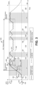
- FIG. 3 illustrates the temperature of the same GPU of FIG. 1 executing the same five-kernel SWL represented in FIG. 1 except with an IWL executed during at least some portion(s) of some of the idle periods 112, 114, 116, 118, 120, 122 to maintain the temperature of the accelerator above a dynamic target temperature (represented over time by the line identified by reference numeral 302).
- a dynamic target temperature represented over time by the line identified by reference numeral 302
- the dynamic target temperature 302 is defined to be threshold or target temperature delta 304 below an armed maximum temperature of the GPU.
- the armed maximum temperature is the maximum temperature of the GPU observed since the IWL procedure was first armed or initiated.
- the maximum temperature observed corresponds to the current temperature of the GPU.
- the initial armed maximum time corresponds to the temperature of the GPU at the time the IWL procedure is armed.
- the temperature of the GPU continues to increase.
- the armed maximum temperature also increases because each new sample of the temperature constitutes a new maximum since the IWL procedure was armed. If the current temperature of the GPU drops from a previously higher maximum (e.g., at the dip 306 in FIG. 3 ), the armed maximum temperature does not drop but remains at the highest observed temperature.
- the dynamic target temperature 302 is defined to be the target temperature delta 304 below the armed maximum temperature.
- the dynamic target temperature 302 begins at the idle temperature 124 (which is the target temperature delta 304 below the temperature of the GPU at point 204 in this example) and varies over time to follow the increasing temperature of the GPU during the first active period 102.
- the dynamic target temperature 302 remains constant during the dip 306 in the GPU temperature because the armed maximum temperature is also constant during the time.
- the dynamic target temperature 302 then rises in conjunction with the temperature reaching the maximum temperature 128 at point 308 and then the dynamic target temperature remains constant for the remainder of the IWL procedure.
- the target temperature 202 in FIG. 2 is a fixed value that defines both the temperature at which the IWL procedure is armed or initiated and also the target temperature above which the GPU is maintained during the IWL procedure.
- the temperature at which the IWL procedure is armed is defined independent of the dynamic target temperature 302 used during the IWL procedure.
- the dynamic target temperature 302 during the IWL procedure is defined to be a target temperature delta 304 below the armed maximum temperature
- the IWL procedure is first armed or activated when the temperature of the GPU reaches the target temperature delta 304 above a disarmed minimum temperature.
- the disarmed minimum temperature refers to the minimum temperature of the GPU observed since the IWL procedure was last disarmed or ended.
- the minimum temperature observed corresponds to the idle temperature 124.
- the IWL procedure is armed when the GPU temperature rises to a temperature corresponding to the target temperature delta 304 above the idle temperature 124.
- the dynamic target temperature 302 initially begins at the target temperature delta 304 below the temperature of the GPU at the time the IWL is initially armed.
- the initial temperature of the dynamic target temperature 302 corresponds to the disarmed minimum temperature prior to the IWL procedure being armed. This is the reason that the initial target temperature 302 corresponds to the idle temperature 124 when the IWL procedure begins as represented in the illustrated example of FIG. 3 as noted above.
- the initial dynamic target temperature 302 would also be higher than the idle temperature 124.
- the temperature of the GPU is monitored to identify a trigger condition to cause the GPU to execute an IWL to maintain the temperature of the GPU above the target temperature 302.
- the trigger condition corresponds to the temperature of the GPU falling below a setback temperature (T setback ) (represented over time by the line identified by reference numeral 310).
- T setback a setback temperature
- the setback temperature 310 of FIG. 3 serves the same purpose as the setback temperature 206 described above in connection with FIG. 2 .
- the setback temperature 310 varies across time relative to changes in the dynamic target temperature 302. More particularly, the setback temperature 310 of FIG.
- the setback temperature 310 is a configurable parameter defined to be a setback temperature delta 312 above the target temperature 302.
- the setback temperature 310 also increases.
- the execution of an IWL will be initiated to prevent the temperature from falling as low as the target temperature 302.
- large thermal fluctuations that can impose undue stress on the GPU are avoided during the IWL procedure.
- the IWL procedure implemented in the illustrated examples of FIGS. 2 and 3 limits the execution of IWLs to the idle periods 112, 114, 116, 120, 122 so as to not interfere with the performance of the GPU during the active periods.
- SWLs may be scheduled for execution, thereby establishing the GPU as being in an active state, but the SWLs may not require the GPU to operate at full capacity.
- the temperature of the GPU may drop to relatively low temperatures (e.g., below the target temperature 202, 302).
- the IWL procedure may provide IWLs to the GPU for execution during the active periods if needed to maintain the temperature of the GPU above the target temperature 202, 302. In such examples, there would be no need to monitor or determine whether the GPU is in an active state or an idle state. Rather, the only trigger for the execution of an IWL would be whether the current temperature is above or below the setback temperature 206, 310.
- the IWL procedure includes a mechanism to disarm or deactivate prior to the timeout period 208 expiring in response to such situations so as not to exacerbate the problem and increase the frequency and/or extent of thermal fluctuations. For instance, assume the particular SWL executed by the GPU during the first active period 102 results in the temperature of the GPU initially rising enough to trigger the activation or arming of the IWL procedure and then dropping back down close to the idle temperature before the active period 102 ends.
- the trigger condition for executing IWLs based on the temperature of the GPU being below the setback temperature 206, 310 would be satisfied.
- the IWL procedure would provide IWLs to the GPU for execution to drive up the temperature of the GPU toward the setback temperature 206, 301.
- the initial temperature of the GPU at the beginning of the idle period 114 was low (e.g., at or near the idle temperature)
- this process would produce a large thermal fluctuation rather than avoid it.
- a relatively large drop in temperature e.g., above a threshold
- FIG. 4 illustrates an example computing system 400 constructed in accordance with teachings disclosed herein.
- the example computing system 402 includes a processor 402 to execute SWLs provided by a user.
- the processor 402 may be any type of processor such as a central processing unit (CPU), graphics processing unit (GPU), an accelerator, etc.
- the processor 402 includes an example workload scheduler 404 and one or more temperature sensor(s) 406.
- the example workload scheduler 404 receives workloads submitted from a user (e.g., SWLs) and schedules the workloads for execution.
- the example temperature sensor(s) 406 monitor the temperature of the processor 402 and output signals indicative of the temperature.
- the temperature sensor(s) 406 are a means for sensing the temperature of the processor 402.
- one or more of the temperature sensor(s) are included within a package of the processor 402. In some examples, one or more of the temperature sensor(s) 406 are mounted on a surface of a package of the processor 402. In some examples, one or more of the temperature sensor(s) are mounted adjacent to a package of the processor 402 (e.g., on an adjacent PCB).
- the example computing system 400 of FIG. 4 includes an example thermal fluctuation controller 408 to reduce thermal fluctuations in the processor 402 due to the heating and cooling of the processor 402 during active and idle periods as outlined above in connection with FIGS. 1-3 . That is, the example thermal fluctuation controller 408 monitors the temperature of the processor 402 and the activity of the processor 402 to provide IWLs for execution by the processor 402 at suitable times (e.g., during idle periods) to maintain the temperature of the processor 402 within a threshold range of a peak temperature. As represented in the illustrated example of FIG. 4 , the thermal fluctuation controller 408 is external to the processor 402 and associated with a separate processor.
- the thermal fluctuation controller 408 may be implemented by a CPU that interacts with the processor 402, which may be a GPU. In other examples, the thermal fluctuation controller 408 may be internal to and implemented by the processor 402 itself. In some examples, at least some functionalities of the thermal fluctuation controller 408 are implemented internally by the processor 402 and at least some functionalities of the thermal fluctuation controller 408 are implemented externally by a different processor.
- the thermal fluctuation controller 408 includes an example workload analyzer 410, an example temperature analyzer 412, an example idle workload controller 414, an example timer 416, example memory 418, and an example idle workload database 420.
- the example workload analyzer 410 analyzes the current state of the processor 402 to determine whether the processor 402 is currently active (e.g., executing or scheduled to execute a SWL) or currently idle (e.g., in an idle period). More particularly, in some examples, the workload analyzer 410 is in communication with the workload scheduler 404 of the processor 402 and/or has access to schedule information generated by the workload scheduler 404.
- the workload analyzer 410 analyzes such schedule information to confirm whether any SWL submissions have been provided to the scheduler for execution. If at least one SWL submission is scheduled for execution, the workload analyzer 410 determines that the processor 402 is in an active state with pending SWLs to execute. If the schedule information indicates that no pending SWL submissions are scheduled to be executed, the workload analyzer 410 determines that the processor 402 is in an idle state.
- the workload analyzer 410 is one of hardware, firmware, or software.
- the workload analyzer 410 is a processor, a dedicated processor unit, a digital signal processor (DSP), etc.
- the example workload analyzer 410 may be a block of code embodied as transistor logic (firmware) or software.
- the example temperature analyzer 412 is in communication with the temperature sensor(s) 406 of the processor 402 and/or has access to the temperature data output by the temperature sensor(s) 406. In some examples, the temperature analyzer 412 analyzes the temperature data to determine a temperature of the processor 402. In some examples, different portions of the processor 402 may be at different temperatures such that different temperature sensors 406 output different measured temperatures. In some examples, the temperature analyzer 412 identifies the highest reported temperature as the temperature of the processor 402 to be used in subsequent analysis. In some examples, a different temperature than the highest reported temperature may be used (e.g., the lowest reported temperature, an average of temperatures reported by some or all of the temperature sensors 406, etc.).
- the temperature analyzer 412 compares the temperature of the processor 402 to one or more parameters (e.g., thresholds, set points, temperature ranges, etc.) associated with the initiation and/or implementation of the IWL procedure discussed above in connection with FIGS. 1-3 . For example, if a fixed target temperature 202 is defined, the temperature analyzer 412 compares the temperature of processor 402 to the target temperature 202 to determine when to arm or enable the IWL procedure. If a dynamic target temperature 302 is to be used, the temperature analyzer 412 compares the temperature of the processor 402 to the disarmed minimum temperature plus the target temperature delta 304 to determine when to arm the IWL procedure.
- parameters e.g., thresholds, set points, temperature ranges, etc.
- the temperature analyzer 412 compares the temperature of the processor 402 to the setback temperature (which may be a fixed setback temperature 206 as described in FIG. 2 or a dynamic setback temperature 310 as described in FIG. 3 ) to determine whether an IWL needs to be executed to maintain the temperature of the processor 402 above the corresponding target temperature 202, 302.
- the temperature analyzer 412 is one of hardware, firmware, or software.
- the temperature analyzer 412 is a processor, a dedicated processor unit, a digital signal processor (DSP), etc.
- the example workload analyzer 410 may be a block of code embodied as transistor logic (firmware) or software.
- the temperature analyzer 412 includes and/or is incorporated with the temperature sensor(s) 406.
- the example idle workload controller 408 of the illustrated example controls the initiation, operation, and termination of the IWL procedure.
- the idle workload controller 408 as a structure, is a means for controlling an IWL procedure. That is, when feedback from the temperature analyzer 412 indicates that the temperature conditions indicate the IWL procedure is to be armed, the idle workload controller 414 arms or initiates the IWL procedure. When feedback from the temperature analyzer 412 indicates the temperature of the processor 402 has dropped below the setback temperature 206, 310, the idle workload controller determines whether to submit an IWL submission to the workload scheduler 404 of the processor 402 to execute the IWL. In some examples, execution of an IWL is to be limited to idle periods.
- the idle workload controller 414 also uses feedback from the workload analyzer 410 to determine whether the processor 402 is currently in an active state or an idle state.
- the particular IWL provided to the processor 402 for execution is selected from the idle workload database 420.
- the different IWLs may correspond to any suitable set of commands that may be provided to the processor for execution. Different IWLs may be defined to affect the temperature of the processor 402 in different ways (e.g., heat it faster or slower).
- the IWLs are defined as relatively simply workloads that may be looped so that execution may be ongoing until such time as the IWL is no longer needed (e.g., the temperature of the processor 402 has been raised back up to or above the setback temperature 206, 310).
- the IWLs are defined to have multiple threads to cause different execution units of the processor 402 to operate at the same time for a more evenly distributed heating of the GPU.
- the example timer 416 of the example thermal fluctuation controller 408 is used by the idle workload controller 414 to determine when to end or disarm the IWL procedure. That is, in some examples, the idle workload controller 414 starts the timer 416 when the IWL procedure is first armed. When the timer 416 reaches the timeout period 208, the idle workload controller 414 terminates or disarms the IWL procedure.
- the example memory 418 is used to store values for the parameters used during the IWL procedure. In some examples, these values may be configured once by a user (or defined by an original equipment manufacturer) and remain fixed until changed by the user (e.g., the fixed target temperature 202, the temperature setback 206, the timeout period 208, the target temperature delta 304, the setback temperature delta 312). In some examples, the values in the memory are updated on an ongoing basis based on changing circumstances (e.g., the dynamic target temperature 302, the dynamic setback temperature 310, the armed maximum temperature, the disarmed minimum temperature, the current temperature of the processor 402, etc.).
- thermal fluctuation controller 408 While an example manner of implementing the thermal fluctuation controller 408 is illustrated in FIG. 4 , one or more of the elements, processes and/or devices illustrated in FIG. 4 may be combined, divided, rearranged, omitted, eliminated and/or implemented in any other way. Further, the example workload analyzer 410, the example temperature analyzer 412, the example idle workload controller 414, the example timer 416, the example memory 418, the example idle workload database 420, and/or, more generally, the example thermal fluctuation controller 408 of FIG. 4 may be implemented by hardware, software, firmware and/or any combination of hardware, software and/or firmware.
- any of the example workload analyzer 410, the example temperature analyzer 412, the example idle workload controller 414, the example timer 416, the example memory 418, the example idle workload database 420 and/or, more generally, the example thermal fluctuation controller 408 could be implemented by one or more analog or digital circuit(s), logic circuits, programmable processor(s), programmable controller(s), graphics processing unit(s) (GPU(s)), digital signal processor(s) (DSP(s)), application specific integrated circuit(s) (ASIC(s)), programmable logic device(s) (PLD(s)) and/or field programmable logic device(s) (FPLD(s)).
- At least one of the example workload analyzer 410, the example temperature analyzer 412, the example idle workload controller 414, the example timer 416, the example memory 418, and/or the example idle workload database 420 is/are hereby expressly defined to include a non-transitory computer readable storage device or storage disk such as a memory, a digital versatile disk (DVD), a compact disk (CD), a Blu-ray disk, etc. including the software and/or firmware.
- the example thermal fluctuation controller 408 may include one or more elements, processes and/or devices in addition to, or instead of, those illustrated in FIG.
- the phrase "in communication,” including variations thereof, encompasses direct communication and/or indirect communication through one or more intermediary components, and does not require direct physical (e.g., wired) communication and/or constant communication, but rather additionally includes selective communication at periodic intervals, scheduled intervals, aperiodic intervals, and/or one-time events.
- FIGS. 5 and 6 Flowcharts representative of example hardware logic, machine readable instructions, hardware implemented state machines, and/or any combination thereof for implementing the thermal fluctuation controller 408 of FIG. 4 is shown in FIGS. 5 and 6 .
- the machine readable instructions may be one or more executable programs or portion(s) of an executable program for execution by a computer processor and/or processor circuitry, such as the processor 712 shown in the example processor platform 700 discussed below in connection with FIG. 7 .
- the program may be embodied in software stored on a non-transitory computer readable storage medium such as a CD-ROM, a floppy disk, a hard drive, a DVD, a Blu-ray disk, or a memory associated with the processor 712, but the entire program and/or parts thereof could alternatively be executed by a device other than the processor 712 and/or embodied in firmware or dedicated hardware.
- a non-transitory computer readable storage medium such as a CD-ROM, a floppy disk, a hard drive, a DVD, a Blu-ray disk, or a memory associated with the processor 712, but the entire program and/or parts thereof could alternatively be executed by a device other than the processor 712 and/or embodied in firmware or dedicated hardware.
- a non-transitory computer readable storage medium such as a CD-ROM, a floppy disk, a hard drive, a DVD, a Blu-ray disk, or a memory associated with the processor 712
- any or all of the blocks may be implemented by one or more hardware circuits (e.g., discrete and/or integrated analog and/or digital circuitry, an FPGA, an ASIC, a comparator, an operational-amplifier (op-amp), a logic circuit, etc.) structured to perform the corresponding operation without executing software or firmware.
- the processor circuitry may be distributed in different network locations and/or local to one or more devices (e.g., a multi-core processor in a single machine, multiple processors distributed across a server rack, etc.).
- the machine readable instructions described herein may be stored in one or more of a compressed format, an encrypted format, a fragmented format, a compiled format, an executable format, a packaged format, etc.
- Machine readable instructions as described herein may be stored as data or a data structure (e.g., portions of instructions, code, representations of code, etc.) that may be utilized to create, manufacture, and/or produce machine executable instructions.
- the machine readable instructions may be fragmented and stored on one or more storage devices and/or computing devices (e.g., servers) located at the same or different locations of a network or collection of networks (e.g., in the cloud, in edge devices, etc.).
- the machine readable instructions may require one or more of installation, modification, adaptation, updating, combining, supplementing, configuring, decryption, decompression, unpacking, distribution, reassignment, compilation, etc. in order to make them directly readable, interpretable, and/or executable by a computing device and/or other machine.
- the machine readable instructions may be stored in multiple parts, which are individually compressed, encrypted, and stored on separate computing devices, wherein the parts when decrypted, decompressed, and combined form a set of executable instructions that implement one or more functions that may together form a program such as that described herein.
- machine readable instructions may be stored in a state in which they may be read by processor circuitry, but require addition of a library (e.g., a dynamic link library (DLL)), a software development kit (SDK), an application programming interface (API), etc. in order to execute the instructions on a particular computing device or other device.
- a library e.g., a dynamic link library (DLL)
- SDK software development kit
- API application programming interface
- the machine readable instructions may need to be configured (e.g., settings stored, data input, network addresses recorded, etc.) before the machine readable instructions and/or the corresponding program(s) can be executed in whole or in part.
- machine readable media may include machine readable instructions and/or program(s) regardless of the particular format or state of the machine readable instructions and/or program(s) when stored or otherwise at rest or in transit.
- the machine readable instructions described herein can be represented by any past, present, or future instruction language, scripting language, programming language, etc.
- the machine readable instructions may be represented using any of the following languages: C, C++, Java, C#, Perl, Python, JavaScript, HyperText Markup Language (HTML), Structured Query Language (SQL), Swift, etc.
- FIGS. 5 and 6 may be implemented using executable instructions (e.g., computer and/or machine readable instructions) stored on a non-transitory computer and/or machine readable medium such as a hard disk drive, a flash memory, a read-only memory, a compact disk, a digital versatile disk, a cache, a random-access memory and/or any other storage device or storage disk in which information is stored for any duration (e.g., for extended time periods, permanently, for brief instances, for temporarily buffering, and/or for caching of the information).
- a non-transitory computer readable medium is expressly defined to include any type of computer readable storage device and/or storage disk and to exclude propagating signals and to exclude transmission media.
- A, B, and/or C refers to any combination or subset of A, B, C such as (1) A alone, (2) B alone, (3) C alone, (4) A with B, (5) A with C, (6) B with C, and (7) A with B and with C.
- the phrase "at least one of A and B" is intended to refer to implementations including any of (1) at least one A, (2) at least one B, and (3) at least one A and at least one B.
- the phrase "at least one of A or B" is intended to refer to implementations including any of (1) at least one A, (2) at least one B, and (3) at least one A and at least one B.
- the phrase "at least one of A and B" is intended to refer to implementations including any of (1) at least one A, (2) at least one B, and (3) at least one A and at least one B.
- the phrase "at least one of A or B" is intended to refer to implementations including any of (1) at least one A, (2) at least one B, and (3) at least one A and at least one B.
- the flowchart of FIG. 5 represents example machine readable instructions to implement the thermal fluctuation controller 408 of FIG. 4 using a fixed target temperature 202 as described above in connection with FIG. 2 .
- the program of FIG. 5 begins at block 502 where the example temperature analyzer 412 obtains the current temperature of the processor 402.
- the example idle workload controller 414 determines whether the IWL procedure is armed. If not, control advances to block 508 where the example temperature analyzer 412 determines whether the current temperature is at or above the target temperature 202. If not, there is no need to arm the IWL procedure. Accordingly, control advances to block 526 where the thermal fluctuation controller 408 determines whether to continue the process. If so, control returns to block 502 to obtain an updated measurement of the current temperature.
- control advances to block 508 where the example idle workload controller 414 arms the IWL procedure.
- arming the IWL procedure initiates the monitoring of the temperature of the processor 402 relative to the setback temperature 206. Further, arming the IWL procedure includes starting the example timer 416 to count towards the timeout period 208. In some examples, rather than starting a timer, the idle workload controller 414 may store the current time (as indicated by the timer 416) in the example memory 418 as a point of reference to compare against the timeout period 208 as time progresses. After the IWL procedure is armed at block 508, control advances to block 526.
- the example idle workload controller 414 determines that the IWL procedure is armed, control advances to block 510.
- the example idle workload controller saves and/or updates (e.g., in the example memory 418) an armed maximum temperature controller. That is, if the most recent measurement of the current temperature (obtained at block 502) is the highest temperature observed since the IWL procedure was first armed, that temperature is set as the armed maximum temperature. If the current temperature is less than the armed maximum temperature, the armed maximum temperature remains unchanged.
- the example idle workload controller 414 determines whether the timeout period 208 has elapsed. If not, control advances to block 514 where the example workload analyzer 410 determines whether any SWL is scheduled. If so, then no IWL is to be executed so as to not interfere with the performance of the processor 402 when executing the SWL. Accordingly, control advances to block 516 where the example temperature analyzer 412 determines whether the armed maximum temperature (set at block 510) minus the current temperature (obtained at block 502) satisfies (e.g., is greater than) a threshold.
- Block 516 serves to identify situations where large temperatures drops (e.g., exceeding the threshold) occur during an active period so as to not inadvertently cause the temperature of the processor 402 to increase during an idle period if it has already cooled during a preceding active period.
- the threshold e.g., the difference between the armed maximum temperature and the current temperature exceeds the threshold
- control advances to block 518 where the example idle workload controller 414 disarms the IWL procedure.
- control advances to block 526 to determine whether to continue the process as discussed above. If the example temperature analyzer 412 determines, at block 516, that the threshold is not satisfied, control advances directly to block 526 such that the IWL procedure remains armed.
- control advances to block 520 where the example temperature analyzer 412 determines whether the current temperature is lower than the setback temperature 206. In some examples, if reliability is more important than performance and the potential for large thermal fluctuations during active periods are to be avoided, blocks 514 and 516 may be omitted. In such examples, if the timeout period has not elapsed (as determined at block 512), control advances directly to block 520. If the example temperature analyzer 412 determines, at block 520, that the current temperature is not lower than the setback temperature 206, then no action needs to be taken so control advances directly to block 526.
- the example idle workload controller 414 provides the IWL to the processor 402 for execution. Thereafter, control advances to block 526.
- control advances to block 518 where the example idle workload controller 414 disarms the IWL procedure. Thereafter, control advances to block 526 to determine whether to continue the process as discussed above. If so, control again returns to block 502. If not, the example process of FIG. 5 ends.
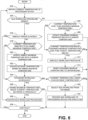
- the flowchart of FIG. 6 represents example machine readable instructions to implement the thermal fluctuation controller 408 of FIG. 4 using a dynamic target temperature 302 as described above in connection with FIG. 3 .
- the program of FIG. 6 begins at block 602 where the example temperature analyzer 412 obtains the current temperature of the processor 402.
- the example idle workload controller 414 determines whether the IWL procedure is armed. If not, control advances to block 608 where the example temperature analyzer 412 determines the current temperature is less than the disarmed minimum temperature. If so, control advanced to block 608 where the idle workload controller 414 updates the disarmed current temperature with the current temperature. That is, the current temperature becomes the new disarmed minimum temperature. Thereafter, control advances to block 636 where the thermal fluctuation controller 408 determines whether to continue the process. If so, control returns to block 602 to obtain an updated measurement of the current temperature.
- arming the IWL procedure includes starting the example timer 416 to count towards the timeout period 208.
- the idle workload controller 414 may store the current time (as indicated by the timer 416) in the example memory 418 as a point of reference to compare against the timeout period 208 as time progresses.
- control advances to block 614 where the example idle workload controller 414 resets the disarmed minimum temperature to an upper bound.
- the upper bound can be any suitable higher any expected temperature for the processor 402 (e.g., higher than the maximum temperature 128).
- control advances to block 616.
- the example idle workload controller 414 determines whether the timeout period 208 has elapsed. If not, control advances to block 618 where the example temperature analyzer 412 determines whether the current temperature is greater than the armed maximum temperature. If so, control advances to block 620 where the idle workload controller 414 updates the armed maximum temperature with the current temperature. That is, the current temperature becomes the new armed maximum temperature.
- the idle workload controller updates the setback temperature 310 based on the updated armed maximum temperature.
- the setback temperature 310 is defined as the armed maximum temperature minus the target temperature delta 304 plus the setback temperature delta 312. Thereafter, control advances to block 624. Returning to block 618, if the current temperature is not greater than the armed maximum temperature, control advances directly to block 624.
- the example workload analyzer 410 determines whether any SWL is scheduled. If so, then no IWL is to be executed so as to not interfere with the performance of the processor 402 when executing the SWL. Accordingly, control advances to block 626 where the example temperature analyzer 412 determines whether the armed maximum temperature (set at block 620) minus the current temperature (obtained at block 602) satisfies (e.g., is greater than) a threshold. Block 626 serves to identify situations where large temperatures drops (e.g., exceeding the threshold) occur during an active period so as to not inadvertently cause the temperature of the processor 402 to increase during an idle period if it has already cooled during a preceding active period.
- Block 626 serves to identify situations where large temperatures drops (e.g., exceeding the threshold) occur during an active period so as to not inadvertently cause the temperature of the processor 402 to increase during an idle period if it has already cooled during a preceding active period.
- the threshold e.g., the difference between the armed maximum temperature and the current temperature exceeds the threshold
- control advances to block 630 where the example temperature analyzer 412 determines whether the current temperature is lower than the setback temperature 310. In some examples, if reliability is more important than performance and the potential for large thermal fluctuations during active periods are to be avoided, blocks 622 and 624 may be omitted. In such examples, control advances from blocks 618 and 622 directly to block 630. If the example temperature analyzer 412 determines, at block 630, that the current temperature is not lower than the setback temperature 206, then no action needs to be taken so control advances directly to block 636.
- the example idle workload controller 414 provides the IWL to the processor 402 for execution. Thereafter, control advances to block 636.
- control advances to block 628 where the example idle workload controller 414 disarms the IWL procedure. Thereafter, control advances to block 636 to determine whether to continue the process as discussed above. If so, control again returns to block 602. If not, the example process of FIG. 6 ends.
- FIG. 7 is a block diagram of an example processor platform 700 structured to execute the instructions of FIGS. 5 and 6 to implement the thermal fluctuation controller 408 of FIG. 4 .
- the processor platform 700 can be, for example, a server, a personal computer, a workstation, a self-learning machine (e.g., a neural network), a mobile device (e.g., a cell phone, a smart phone, a tablet such as an iPad TM ), a personal digital assistant (PDA), an Internet appliance, a DVD player, a CD player, a digital video recorder, a Blu-ray player, a gaming console, a personal video recorder, a set top box, a headset or other wearable device, or any other type of computing device.
- a self-learning machine e.g., a neural network
- a mobile device e.g., a cell phone, a smart phone, a tablet such as an iPad TM
- PDA personal digital assistant
- an Internet appliance e.g.,
- the processor platform 700 of the illustrated example includes a processor 712.
- the processor 712 of the illustrated example is hardware.
- the processor 712 can be implemented by one or more integrated circuits, logic circuits, microprocessors, GPUs, DSPs, or controllers from any desired family or manufacturer.
- the hardware processor may be a semiconductor based (e.g., silicon based) device.
- the processor implements the example workload analyzer 410, the example temperature analyzer 412, the example idle workload controller 414, and the example timer 416.
- the processor 712 of the illustrated example includes a local memory 713 (e.g., a cache).
- the processor 712 of the illustrated example is in communication with a main memory including a volatile memory 714 and a non-volatile memory 716 via a bus 718.
- the volatile memory 714 may be implemented by Synchronous Dynamic Random Access Memory (SDRAM), Dynamic Random Access Memory (DRAM), RAMBUS ® Dynamic Random Access Memory (RDRAM ® ) and/or any other type of random access memory device.
- the non-volatile memory 716 may be implemented by flash memory and/or any other desired type of memory device. Access to the main memory 714, 716 is controlled by a memory controller.
- the processor platform 700 of the illustrated example also includes an interface circuit 720.
- the interface circuit 720 may be implemented by any type of interface standard, such as an Ethernet interface, a universal serial bus (USB), a Bluetooth ® interface, a near field communication (NFC) interface, and/or a PCI express interface.
- one or more input devices 722 are connected to the interface circuit 720.
- the input device(s) 722 permit(s) a user to enter data and/or commands into the processor 712.
- the input device(s) can be implemented by, for example, an audio sensor, a microphone, a camera (still or video), a keyboard, a button, a mouse, a touchscreen, a track-pad, a trackball, isopoint and/or a voice recognition system.
- One or more output devices 724 are also connected to the interface circuit 720 of the illustrated example.
- the output devices 724 can be implemented, for example, by display devices (e.g., a light emitting diode (LED), an organic light emitting diode (OLED), a liquid crystal display (LCD), a cathode ray tube display (CRT), an in-place switching (IPS) display, a touchscreen, etc.), a tactile output device, a printer and/or speaker.
- display devices e.g., a light emitting diode (LED), an organic light emitting diode (OLED), a liquid crystal display (LCD), a cathode ray tube display (CRT), an in-place switching (IPS) display, a touchscreen, etc.
- the interface circuit 720 of the illustrated example thus, typically includes a graphics driver card, a graphics driver chip and/or a graphics driver processor.
- the interface circuit 720 of the illustrated example also includes a communication device such as a transmitter, a receiver, a transceiver, a modem, a residential gateway, a wireless access point, and/or a network interface to facilitate exchange of data with external machines (e.g., computing devices of any kind) via a network 726.
- the communication can be via, for example, an Ethernet connection, a digital subscriber line (DSL) connection, a telephone line connection, a coaxial cable system, a satellite system, a line-of-site wireless system, a cellular telephone system, etc.
- DSL digital subscriber line
- the processor platform 700 of the illustrated example also includes one or more mass storage devices 728 for storing software and/or data.
- mass storage devices 728 include floppy disk drives, hard drive disks, compact disk drives, Blu-ray disk drives, redundant array of independent disks (RAID) systems, and digital versatile disk (DVD) drives.
- the mass storage device implements the example memory 418, and/or the example idle workload database 420
- the machine executable instructions 732 of FIGS. 5 and 6 may be stored in the mass storage device 728, in the volatile memory 714, in the non-volatile memory 716, and/or on a removable non-transitory computer readable storage medium such as a CD or DVD.
- example methods, apparatus and articles of manufacture have been disclosed that improve the reliability and/or useful life of a processor by reducing the frequency, number, and/or severity of large thermal fluctuations in the processor between active and idle periods of use. Furthermore, examples disclosed herein achieve this technological benefit without impacting the performance of the processor.
- the disclosed methods, apparatus and articles of manufacture are accordingly directed to one or more improvement(s) in the functioning of a computer.
Landscapes
- Engineering & Computer Science (AREA)
- Theoretical Computer Science (AREA)
- Physics & Mathematics (AREA)
- General Physics & Mathematics (AREA)
- Software Systems (AREA)
- General Engineering & Computer Science (AREA)
- Automation & Control Theory (AREA)
- Human Computer Interaction (AREA)
- Cooling Or The Like Of Electrical Apparatus (AREA)
- Microcomputers (AREA)
- Control Of Temperature (AREA)
- Programmable Controllers (AREA)
Claims (12)
- Einrichtung, die umfasst:ein Mittel (406) zum Erfassen einer aktuellen Temperatur eines Prozessors (402) undein Mittel (414) zum Steuern einer Ruhearbeitslastprozedur, wobei das Steuermittel (414) eine Ruhearbeitslast an den Prozessor (402) bereitstellt, die als Reaktion darauf ausgeführt werden soll, dass die aktuelle Temperatur unter eine Rücksetztemperatur fällt,dadurch gekennzeichnet, dass das Steuermittel (414) die Ruhearbeitslast an den Prozessor (402) bereitstellen soll, wenn die Ruhearbeitslastprozedur aktiviert ist, und die Ruhearbeitslast nicht an den Prozessor (202) bereitstellen soll, wenn die Ruhearbeitslastprozedur deaktiviert ist, undwobei das Steuermittel (414) die Ruhearbeitslastprozedur als Reaktion darauf deaktivieren soll, dass ein Zeitüberschreitungszeitraum (208) seit der letzten Aktivierung der Ruhearbeitslastprozedur abläuft.
- Einrichtung nach Anspruch 1, wobei das Steuermittel (414) die Ruhearbeitslastprozedur als Reaktion darauf aktivieren soll, dass die aktuelle Temperatur eine Schwellentemperatur überschreitet.
- Einrichtung nach Anspruch 2, wobei die Schwellentemperatur als ein Zieltemperaturdelta über einer deaktivierten Mindesttemperatur definiert ist, wobei die deaktivierte Mindesttemperatur einem niedrigsten Wert entspricht, der für die aktuelle Temperatur des Prozessors seit der letzten Deaktivierung der Ruhearbeitslastprozedur beobachtet wird.
- Einrichtung nach einem der Ansprüche 1-3, wobei das Steuermittel (414) die Ruhearbeitslastprozedur als Reaktion darauf deaktivieren soll, dass ein Ruhezeitraum des Prozessors einen Schwellenzeitraum überschreitet.
- Einrichtung nach einem der Ansprüche 1-4, wobei das Steuermittel (414) die Ruhearbeitslastprozedur als Reaktion darauf deaktivieren soll, dass eine Differenz zwischen der aktuellen Temperatur und einer aktivierten Höchsttemperatur eine Schwelle überschreitet, wobei die aktivierte Höchsttemperatur einem höchsten Wert entspricht, der für die aktuelle Temperatur des Prozessors seit der letzten Aktivierung der Ruhearbeitslastprozedur beobachtet wird.
- Einrichtung nach einem der Ansprüche 1-5, wobei die Rücksetztemperatur ein festgelegtes Temperaturdelta ist, das höher als eine Zieltemperatur ist.
- Einrichtung nach Anspruch 6, wobei die Zieltemperatur durch einen dynamischen Temperaturwert definiert ist, wobei der dynamische Temperaturwert einem Zieltemperaturdelta unter einer aktivierten Höchsttemperatur entspricht, wobei die aktivierte Höchsttemperatur einem höchsten Wert entspricht, der für die aktuelle Temperatur des Prozessors (402) während eines relevanten Zeitraums beobachtet wird.
- Verfahren, das umfasst:Messen einer aktuellen Temperatur eines Prozessors (402) undBewirken, dass der Prozessor (402) eine Ruhearbeitslast ausführt, um Wärme als Reaktion darauf zu erzeugen, dass die aktuelle Temperatur unter eine Rücksetztemperatur fällt,dadurch gekennzeichnet, dass die Ruhearbeitslast an den Prozessor (402) bereitgestellt wird, wenn eine Ruhearbeitslastprozedur aktiviert ist, und die Ruhearbeitslast nicht an den Prozessor (402) bereitgestellt wird, wenn die Ruhearbeitslastprozedur deaktiviert ist, undwobei das Verfahren ferner ein Deaktivieren der Ruhearbeitslastprozedur als Reaktion darauf umfasst,dass ein Zeitüberschreitungszeitraum seit der letzten Aktivierung der Ruhearbeitslastprozedur abläuft.
- Verfahren nach Anspruch 8, das ferner ein Bereitstellen der Ruhearbeitslast an den Prozessor (402) aufweist, wenn sich der Prozessor (402) in einem Ruhezustand befindet, wobei die Ruhearbeitslast nicht an den Prozessor (402) bereitgestellt wird, wenn sich der Prozessor (402) in einem aktiven Zustand befindet.
- Verfahren nach Anspruch 9, das ferner ein Bestimmen aufweist, ob sich der Prozessor (402) im Ruhezustand oder im aktiven Zustand befindet, basierend darauf, ob eine Standardarbeitslast zur Ausführung durch den Prozessor (402) geplant ist.
- Verfahren nach Anspruch 8, das ferner ein Aktivieren der Ruhearbeitslastprozedur als Reaktion darauf aufweist, dass die aktuelle Temperatur eine Schwellentemperatur überschreitet.
- Computerlesbare Speichervorrichtung, die Anweisungen umfasst, die, wenn sie ausgeführt werden, eine Maschine veranlassen, das Verfahren nach einem der Ansprüche 8-11 zu implementieren.
Applications Claiming Priority (1)
| Application Number | Priority Date | Filing Date | Title |
|---|---|---|---|
| US17/133,279 US12135569B2 (en) | 2020-12-23 | 2020-12-23 | Methods and apparatus to reduce thermal fluctuations in semiconductor processors |
Publications (2)
| Publication Number | Publication Date |
|---|---|
| EP4020125A1 EP4020125A1 (de) | 2022-06-29 |
| EP4020125B1 true EP4020125B1 (de) | 2025-02-19 |
Family
ID=76858083
Family Applications (1)
| Application Number | Title | Priority Date | Filing Date |
|---|---|---|---|
| EP21210860.9A Active EP4020125B1 (de) | 2020-12-23 | 2021-11-26 | Verfahren und vorrichtung zur reduzierung von thermischen schwankungen in halbleiterprozessoren |
Country Status (4)
| Country | Link |
|---|---|
| US (1) | US12135569B2 (de) |
| EP (1) | EP4020125B1 (de) |
| JP (1) | JP2022100230A (de) |
| CN (1) | CN114661435A (de) |
Families Citing this family (2)
| Publication number | Priority date | Publication date | Assignee | Title |
|---|---|---|---|---|
| US12253901B2 (en) | 2021-09-30 | 2025-03-18 | Intel Corporation | Systems and methods for stable and elevated idle-mode temperature for assembled semiconductor devices |
| US20230305608A1 (en) * | 2022-03-23 | 2023-09-28 | Microsoft Technology Licensing, Llc | Device-internal climate control for hardware preservation |
Family Cites Families (16)
| Publication number | Priority date | Publication date | Assignee | Title |
|---|---|---|---|---|
| US5752011A (en) | 1994-06-20 | 1998-05-12 | Thomas; C. Douglas | Method and system for controlling a processor's clock frequency in accordance with the processor's temperature |
| US7032119B2 (en) * | 2000-09-27 | 2006-04-18 | Amphus, Inc. | Dynamic power and workload management for multi-server system |
| JP2006113724A (ja) * | 2004-10-13 | 2006-04-27 | Omron Corp | 制御方法、温度制御方法、温度調節器、熱処理装置、プログラムおよび記録媒体 |
| US8374730B2 (en) * | 2005-08-25 | 2013-02-12 | Apple Inc. | Methods and apparatuses for dynamic thermal control |
| US7848901B2 (en) * | 2005-11-29 | 2010-12-07 | International Business Machines Corporation | Tracing thermal data via performance monitoring |
| JP4855806B2 (ja) * | 2006-03-02 | 2012-01-18 | 株式会社三社電機製作所 | 電源装置 |
| US7949889B2 (en) * | 2008-01-07 | 2011-05-24 | Apple Inc. | Forced idle of a data processing system |
| US8449173B1 (en) * | 2008-04-10 | 2013-05-28 | Google Inc. | Method and system for thermal testing of computing system components |
| US8214658B2 (en) | 2008-08-20 | 2012-07-03 | International Business Machines Corporation | Enhanced thermal management for improved module reliability |
| US8942857B2 (en) * | 2011-04-22 | 2015-01-27 | Qualcomm Incorporated | Method and system for thermal load management in a portable computing device |
| US20130000871A1 (en) * | 2011-06-30 | 2013-01-03 | Ian Olson | Systems and Methods for Extending Operating Temperatures of Electronic Components |
| US9122464B2 (en) | 2011-12-22 | 2015-09-01 | Intel Corporation | Method, apparatus, and system for energy efficiency and energy conservation including energy efficient processor thermal throttling using deep power down mode |
| TWI443496B (zh) | 2012-11-01 | 2014-07-01 | Asustek Comp Inc | 電子裝置與超頻運作的工作頻率控制方法 |
| US11238917B2 (en) | 2018-10-23 | 2022-02-01 | Micron Technology, Inc. | Mode-dependent heating of a memory device |
| US11181969B2 (en) | 2019-04-02 | 2021-11-23 | Dell Products, Lp | Method and system for graphics processor unit busy state detection |
| US12253901B2 (en) | 2021-09-30 | 2025-03-18 | Intel Corporation | Systems and methods for stable and elevated idle-mode temperature for assembled semiconductor devices |
-
2020
- 2020-12-23 US US17/133,279 patent/US12135569B2/en active Active
-
2021
- 2021-10-27 JP JP2021175559A patent/JP2022100230A/ja active Pending
- 2021-11-23 CN CN202111394978.7A patent/CN114661435A/zh active Pending
- 2021-11-26 EP EP21210860.9A patent/EP4020125B1/de active Active
Also Published As
| Publication number | Publication date |
|---|---|
| JP2022100230A (ja) | 2022-07-05 |
| EP4020125A1 (de) | 2022-06-29 |
| CN114661435A (zh) | 2022-06-24 |
| US20210223805A1 (en) | 2021-07-22 |
| US12135569B2 (en) | 2024-11-05 |
Similar Documents
| Publication | Publication Date | Title |
|---|---|---|
| US20220334948A1 (en) | Methods and apparatus to improve performance data collection of a high performance computing application | |
| US12013719B2 (en) | Methods and apparatus to dynamically configure overclocking frequency | |
| KR101629879B1 (ko) | 캐시 사용 기반 어댑티브 스케줄링을 가지는 멀티코어 컴퓨터 시스템 | |
| US10067805B2 (en) | Technologies for offloading and on-loading data for processor/coprocessor arrangements | |
| EP4020125B1 (de) | Verfahren und vorrichtung zur reduzierung von thermischen schwankungen in halbleiterprozessoren | |
| CN110199241B (zh) | 自适应功率控制环路 | |
| AU2012379690B2 (en) | Scheduling tasks among processor cores | |
| US12430283B2 (en) | Methods, systems, and apparatus to reconfigure a computer | |
| US20180224871A1 (en) | System and method for thermal management of a wearable computing device based on proximity to a user | |
| US12253901B2 (en) | Systems and methods for stable and elevated idle-mode temperature for assembled semiconductor devices | |
| US12190173B2 (en) | Methods and apparatus for power sharing between discrete processors | |
| US10203747B2 (en) | Workload placement based on heterogeneous compute performance per watt | |
| KR20140002072A (ko) | 휴대용 컴퓨팅 디바이스에서의 열 로드 관리 | |
| US20090055634A1 (en) | Compiling method, apparatus, and program | |
| JP2017142836A (ja) | オペレーティングシステムの挙動を修正する方法及びデバイス | |
| US12306702B2 (en) | Controlling an amount of data used by a baseboard management conroller to perform hardware failure prediction | |
| US20160117199A1 (en) | Computing system with thermal mechanism and method of operation thereof | |
| US20130179893A1 (en) | Adaptation of Probing Frequency for Resource Consumption | |
| US12386749B2 (en) | Controlling memory frequency based on transaction queue occupancy | |
| US20220326096A1 (en) | Methods, systems, and apparatus to generate logic based thermal degradation alerts in compute devices | |
| US20260119356A1 (en) | Methods and apparatus for temperature based re-training of memory access parameters | |
| US10067483B1 (en) | Controlling electrical device based on temperature and voltage | |
| JP5692137B2 (ja) | 消費電力制御装置、情報処理装置、消費電力制御方法、及びプログラム | |
| JP6477032B2 (ja) | プロセッサおよびその制御方法 | |
| JP2016206899A (ja) | 情報処理システム、測定方法及びそのためのプログラム |
Legal Events
| Date | Code | Title | Description |
|---|---|---|---|
| PUAI | Public reference made under article 153(3) epc to a published international application that has entered the european phase |
Free format text: ORIGINAL CODE: 0009012 |
|
| STAA | Information on the status of an ep patent application or granted ep patent |
Free format text: STATUS: THE APPLICATION HAS BEEN PUBLISHED |
|
| AK | Designated contracting states |
Kind code of ref document: A1 Designated state(s): AL AT BE BG CH CY CZ DE DK EE ES FI FR GB GR HR HU IE IS IT LI LT LU LV MC MK MT NL NO PL PT RO RS SE SI SK SM TR |
|
| STAA | Information on the status of an ep patent application or granted ep patent |
Free format text: STATUS: REQUEST FOR EXAMINATION WAS MADE |
|
| 17P | Request for examination filed |
Effective date: 20230102 |
|
| RBV | Designated contracting states (corrected) |
Designated state(s): AL AT BE BG CH CY CZ DE DK EE ES FI FR GB GR HR HU IE IS IT LI LT LU LV MC MK MT NL NO PL PT RO RS SE SI SK SM TR |
|
| RIC1 | Information provided on ipc code assigned before grant |
Ipc: G05D 23/19 20060101ALI20240724BHEP Ipc: G06F 1/3215 20190101ALI20240724BHEP Ipc: G06F 1/3234 20190101ALI20240724BHEP Ipc: G06F 1/329 20190101ALI20240724BHEP Ipc: G06F 9/48 20060101ALI20240724BHEP Ipc: G06F 1/20 20060101AFI20240724BHEP |
|
| GRAP | Despatch of communication of intention to grant a patent |
Free format text: ORIGINAL CODE: EPIDOSNIGR1 |
|
| STAA | Information on the status of an ep patent application or granted ep patent |
Free format text: STATUS: GRANT OF PATENT IS INTENDED |
|
| INTG | Intention to grant announced |
Effective date: 20240909 |
|
| GRAS | Grant fee paid |
Free format text: ORIGINAL CODE: EPIDOSNIGR3 |
|
| GRAA | (expected) grant |
Free format text: ORIGINAL CODE: 0009210 |
|
| STAA | Information on the status of an ep patent application or granted ep patent |
Free format text: STATUS: THE PATENT HAS BEEN GRANTED |
|
| AK | Designated contracting states |
Kind code of ref document: B1 Designated state(s): AL AT BE BG CH CY CZ DE DK EE ES FI FR GB GR HR HU IE IS IT LI LT LU LV MC MK MT NL NO PL PT RO RS SE SI SK SM TR |
|
| REG | Reference to a national code |
Ref country code: GB Ref legal event code: FG4D |
|
| REG | Reference to a national code |
Ref country code: CH Ref legal event code: EP |
|
| REG | Reference to a national code |
Ref country code: IE Ref legal event code: FG4D |
|
| REG | Reference to a national code |
Ref country code: DE Ref legal event code: R096 Ref document number: 602021026310 Country of ref document: DE |
|
| P01 | Opt-out of the competence of the unified patent court (upc) registered |
Free format text: CASE NUMBER: APP_6544/2025 Effective date: 20250207 |
|
| REG | Reference to a national code |
Ref country code: NL Ref legal event code: FP |
|
| PG25 | Lapsed in a contracting state [announced via postgrant information from national office to epo] |
Ref country code: RS Free format text: LAPSE BECAUSE OF FAILURE TO SUBMIT A TRANSLATION OF THE DESCRIPTION OR TO PAY THE FEE WITHIN THE PRESCRIBED TIME-LIMIT Effective date: 20250519 |
|
| PG25 | Lapsed in a contracting state [announced via postgrant information from national office to epo] |
Ref country code: FI Free format text: LAPSE BECAUSE OF FAILURE TO SUBMIT A TRANSLATION OF THE DESCRIPTION OR TO PAY THE FEE WITHIN THE PRESCRIBED TIME-LIMIT Effective date: 20250219 |
|
| PG25 | Lapsed in a contracting state [announced via postgrant information from national office to epo] |
Ref country code: PL Free format text: LAPSE BECAUSE OF FAILURE TO SUBMIT A TRANSLATION OF THE DESCRIPTION OR TO PAY THE FEE WITHIN THE PRESCRIBED TIME-LIMIT Effective date: 20250219 |
|
| PG25 | Lapsed in a contracting state [announced via postgrant information from national office to epo] |
Ref country code: ES Free format text: LAPSE BECAUSE OF FAILURE TO SUBMIT A TRANSLATION OF THE DESCRIPTION OR TO PAY THE FEE WITHIN THE PRESCRIBED TIME-LIMIT Effective date: 20250219 |
|
| REG | Reference to a national code |
Ref country code: LT Ref legal event code: MG9D |
|
| PG25 | Lapsed in a contracting state [announced via postgrant information from national office to epo] |
Ref country code: IS Free format text: LAPSE BECAUSE OF FAILURE TO SUBMIT A TRANSLATION OF THE DESCRIPTION OR TO PAY THE FEE WITHIN THE PRESCRIBED TIME-LIMIT Effective date: 20250619 Ref country code: NO Free format text: LAPSE BECAUSE OF FAILURE TO SUBMIT A TRANSLATION OF THE DESCRIPTION OR TO PAY THE FEE WITHIN THE PRESCRIBED TIME-LIMIT Effective date: 20250519 |
|
| PG25 | Lapsed in a contracting state [announced via postgrant information from national office to epo] |
Ref country code: HR Free format text: LAPSE BECAUSE OF FAILURE TO SUBMIT A TRANSLATION OF THE DESCRIPTION OR TO PAY THE FEE WITHIN THE PRESCRIBED TIME-LIMIT Effective date: 20250219 |
|
| PG25 | Lapsed in a contracting state [announced via postgrant information from national office to epo] |
Ref country code: LV Free format text: LAPSE BECAUSE OF FAILURE TO SUBMIT A TRANSLATION OF THE DESCRIPTION OR TO PAY THE FEE WITHIN THE PRESCRIBED TIME-LIMIT Effective date: 20250219 Ref country code: PT Free format text: LAPSE BECAUSE OF FAILURE TO SUBMIT A TRANSLATION OF THE DESCRIPTION OR TO PAY THE FEE WITHIN THE PRESCRIBED TIME-LIMIT Effective date: 20250620 |
|
| PG25 | Lapsed in a contracting state [announced via postgrant information from national office to epo] |
Ref country code: GR Free format text: LAPSE BECAUSE OF FAILURE TO SUBMIT A TRANSLATION OF THE DESCRIPTION OR TO PAY THE FEE WITHIN THE PRESCRIBED TIME-LIMIT Effective date: 20250520 Ref country code: BG Free format text: LAPSE BECAUSE OF FAILURE TO SUBMIT A TRANSLATION OF THE DESCRIPTION OR TO PAY THE FEE WITHIN THE PRESCRIBED TIME-LIMIT Effective date: 20250219 |
|
| REG | Reference to a national code |
Ref country code: AT Ref legal event code: MK05 Ref document number: 1768901 Country of ref document: AT Kind code of ref document: T Effective date: 20250219 |
|
| PG25 | Lapsed in a contracting state [announced via postgrant information from national office to epo] |
Ref country code: SE Free format text: LAPSE BECAUSE OF FAILURE TO SUBMIT A TRANSLATION OF THE DESCRIPTION OR TO PAY THE FEE WITHIN THE PRESCRIBED TIME-LIMIT Effective date: 20250219 |
|
| PG25 | Lapsed in a contracting state [announced via postgrant information from national office to epo] |
Ref country code: SM Free format text: LAPSE BECAUSE OF FAILURE TO SUBMIT A TRANSLATION OF THE DESCRIPTION OR TO PAY THE FEE WITHIN THE PRESCRIBED TIME-LIMIT Effective date: 20250219 |
|
| PG25 | Lapsed in a contracting state [announced via postgrant information from national office to epo] |
Ref country code: DK Free format text: LAPSE BECAUSE OF FAILURE TO SUBMIT A TRANSLATION OF THE DESCRIPTION OR TO PAY THE FEE WITHIN THE PRESCRIBED TIME-LIMIT Effective date: 20250219 |
|
| PG25 | Lapsed in a contracting state [announced via postgrant information from national office to epo] |
Ref country code: IT Free format text: LAPSE BECAUSE OF FAILURE TO SUBMIT A TRANSLATION OF THE DESCRIPTION OR TO PAY THE FEE WITHIN THE PRESCRIBED TIME-LIMIT Effective date: 20250219 |
|
| PG25 | Lapsed in a contracting state [announced via postgrant information from national office to epo] |
Ref country code: AT Free format text: LAPSE BECAUSE OF FAILURE TO SUBMIT A TRANSLATION OF THE DESCRIPTION OR TO PAY THE FEE WITHIN THE PRESCRIBED TIME-LIMIT Effective date: 20250219 |
|
| PG25 | Lapsed in a contracting state [announced via postgrant information from national office to epo] |
Ref country code: CZ Free format text: LAPSE BECAUSE OF FAILURE TO SUBMIT A TRANSLATION OF THE DESCRIPTION OR TO PAY THE FEE WITHIN THE PRESCRIBED TIME-LIMIT Effective date: 20250219 Ref country code: EE Free format text: LAPSE BECAUSE OF FAILURE TO SUBMIT A TRANSLATION OF THE DESCRIPTION OR TO PAY THE FEE WITHIN THE PRESCRIBED TIME-LIMIT Effective date: 20250219 |
|
| PG25 | Lapsed in a contracting state [announced via postgrant information from national office to epo] |
Ref country code: RO Free format text: LAPSE BECAUSE OF FAILURE TO SUBMIT A TRANSLATION OF THE DESCRIPTION OR TO PAY THE FEE WITHIN THE PRESCRIBED TIME-LIMIT Effective date: 20250219 |
|
| PG25 | Lapsed in a contracting state [announced via postgrant information from national office to epo] |
Ref country code: SK Free format text: LAPSE BECAUSE OF FAILURE TO SUBMIT A TRANSLATION OF THE DESCRIPTION OR TO PAY THE FEE WITHIN THE PRESCRIBED TIME-LIMIT Effective date: 20250219 |
|
| PGFP | Annual fee paid to national office [announced via postgrant information from national office to epo] |
Ref country code: NL Payment date: 20251024 Year of fee payment: 5 |
|
| REG | Reference to a national code |
Ref country code: DE Ref legal event code: R097 Ref document number: 602021026310 Country of ref document: DE |
|
| PLBE | No opposition filed within time limit |
Free format text: ORIGINAL CODE: 0009261 |
|
| STAA | Information on the status of an ep patent application or granted ep patent |
Free format text: STATUS: NO OPPOSITION FILED WITHIN TIME LIMIT |
|
| PGFP | Annual fee paid to national office [announced via postgrant information from national office to epo] |
Ref country code: DE Payment date: 20250930 Year of fee payment: 5 |
|
| PGFP | Annual fee paid to national office [announced via postgrant information from national office to epo] |
Ref country code: GB Payment date: 20251016 Year of fee payment: 5 |
|
| PGFP | Annual fee paid to national office [announced via postgrant information from national office to epo] |
Ref country code: FR Payment date: 20251023 Year of fee payment: 5 |
|
| 26N | No opposition filed |
Effective date: 20251120 |