EP4020048A1 - Optical-fiber ribbon with adhesive-free gaps - Google Patents
Optical-fiber ribbon with adhesive-free gaps Download PDFInfo
- Publication number
- EP4020048A1 EP4020048A1 EP21213420.9A EP21213420A EP4020048A1 EP 4020048 A1 EP4020048 A1 EP 4020048A1 EP 21213420 A EP21213420 A EP 21213420A EP 4020048 A1 EP4020048 A1 EP 4020048A1
- Authority
- EP
- European Patent Office
- Prior art keywords
- optical
- fiber assembly
- fiber
- bonding
- assembly
- Prior art date
- Legal status (The legal status is an assumption and is not a legal conclusion. Google has not performed a legal analysis and makes no representation as to the accuracy of the status listed.)
- Pending
Links
Images


Classifications
-
- G—PHYSICS
- G02—OPTICS
- G02B—OPTICAL ELEMENTS, SYSTEMS OR APPARATUS
- G02B6/00—Light guides; Structural details of arrangements comprising light guides and other optical elements, e.g. couplings
- G02B6/44—Mechanical structures for providing tensile strength and external protection for fibres, e.g. optical transmission cables
- G02B6/4401—Optical cables
- G02B6/4403—Optical cables with ribbon structure
- G02B6/4404—Multi-podded
-
- G—PHYSICS
- G02—OPTICS
- G02B—OPTICAL ELEMENTS, SYSTEMS OR APPARATUS
- G02B6/00—Light guides; Structural details of arrangements comprising light guides and other optical elements, e.g. couplings
- G02B6/04—Light guides; Structural details of arrangements comprising light guides and other optical elements, e.g. couplings formed by bundles of fibres
- G02B6/06—Light guides; Structural details of arrangements comprising light guides and other optical elements, e.g. couplings formed by bundles of fibres the relative position of the fibres being the same at both ends, e.g. for transporting images
- G02B6/08—Light guides; Structural details of arrangements comprising light guides and other optical elements, e.g. couplings formed by bundles of fibres the relative position of the fibres being the same at both ends, e.g. for transporting images with fibre bundle in form of plate
-
- G—PHYSICS
- G02—OPTICS
- G02B—OPTICAL ELEMENTS, SYSTEMS OR APPARATUS
- G02B6/00—Light guides; Structural details of arrangements comprising light guides and other optical elements, e.g. couplings
- G02B6/44—Mechanical structures for providing tensile strength and external protection for fibres, e.g. optical transmission cables
- G02B6/4401—Optical cables
- G02B6/441—Optical cables built up from sub-bundles
-
- G—PHYSICS
- G02—OPTICS
- G02B—OPTICAL ELEMENTS, SYSTEMS OR APPARATUS
- G02B6/00—Light guides; Structural details of arrangements comprising light guides and other optical elements, e.g. couplings
- G02B6/44—Mechanical structures for providing tensile strength and external protection for fibres, e.g. optical transmission cables
- G02B6/4479—Manufacturing methods of optical cables
- G02B6/448—Ribbon cables
Definitions
- the present invention relates to optical-fiber ribbons and methods for producing optical-fiber ribbons.
- Optical fibers provide advantages over conventional communication lines. As compared with traditional wire-based networks, optical-fiber communication networks can transmit significantly more information at significantly higher speeds. The amount of data transmitted over optical-fiber cables is continuously increasing worldwide. This is especially so in data centers because of the expansion of cloud computing, which requires that data be received and transmitted in limited physical space. As such, there is an increasing demand for high-fiber-count and high-fiber-density optical cables. Moreover, there is persistent desire to reduce construction costs of access cable networks, making the reduction of optical-cable diameter and weight central to the use of existing facilities (e.g., underground ducts) to reduce installation costs. Another practical requirement is the ability to mass-fusion splice optical fibers to shorten the time required for connecting cables.
- optical-fiber ribbons can preferentially be mass-fusion spliced to simultaneously make multiple optical-fiber connections.
- Conventional optical-fiber ribbons have the disadvantage of rigidity, however, because of the application of a resin layer around the optical-fiber assembly to keep the optical fibers in a parallel plane. This rigidity limits the possibility of increasing fiber density in optical-fiber cables.lt is well known to connect two optical fibers end-to-end by fusion splicing with a laser, electric arc, or the like.
- the splicing usually includes preparing each optical-fiber's end portion by stripping the coatings (e.g., the outer secondary coating and inner primary coating) from each optical fiber's outer glass cladding and inner glass core, and precisely cleaving each optical fiber's outer glass cladding and inner glass core to yield a bare glass end to be spliced.
- the respective cleaved, bare glass ends are precisely aligned in a single-splice, fusion-splicing machine that joins the two optical fibers.
- the splice alignment and other accommodations help to minimize any attenuation at the splice and provide a strong connection between the spliced ends.
- the single-splicing machine typically includes opposite holding mechanisms for respectively holding the optical fibers so that the cleaved, bare glass ends can be precisely aligned.
- each holding mechanism e.g., a single-fiber alignment chuck
- each alignment chuck or holding mechanism can further include a portion for precisely securing each optical fiber's coated portion adjacent to the cleaved, bare end portion.
- each optical-fiber ribbon may include twelve optical fibers that are held together by adhesive material.
- Preparing each optical-fiber ribbon's end portion typically includes separating the constituent optical fibers' respective end portions and then preparing each optical fiber to yield bare glass end portions. For efficiency, the respective cleaved, bare glass ends are precisely aligned in a mass-fusion splicing machine that joins the respective optical fibers.
- the mass-fusion splicing machine typically employs opposite holding mechanisms (e.g., alignment chucks) for respectively securing the optical fibers so that their cleaved, bare glass ends can be precisely aligned.
- each alignment chuck or other holding mechanism can include a platform or tray respectively defining a plurality of V-shaped grooves (e.g., 12 grooves or 24 grooves) for precisely retaining each optical fiber's cleaved, bare end portion.
- each alignment chuck or other holding mechanism can further include a part or a portion for precisely securing each optical fiber's coated portion adjacent to the cleaved, bare end portion.
- Flexible optical-fiber ribbons yield increased optical-fiber density in optical-fiber cables.
- Mass splicing such flexible optical-fiber ribbons requires positioning the optical-fiber ribbons in alignment chucks of a mass-fusion splicing machine, but sometimes the adhesive bonds (e.g., elongated beads) may cause interference within the alignment chucks (e.g., the V-shaped grooves in the alignment chuck).
- the alignment chucks e.g., the V-shaped grooves in the alignment chuck.
- some commercially available alignment chucks e.g., used in mass-fusion splicing machines
- the pitch of the adhesive-bead pattern is too short (e.g., less than about 100 millimeters), because of adhesive-bead interference in the alignment chucks' V-shaped grooves.
- a solution requires applying tension to both ends of the optical-fiber ribbon and positioning the edge of the optical fiber at either end of the alignment chuck to achieve proper loading of the optical-fiber ribbon into the alignment chuck.
- the present invention embraces an optical-fiber ribbon that facilitates mass-fusion splicing via a mass-fusion splicing machine.
- An exemplary optical-fiber ribbon includes intermittent or recurrent gaps along its longitudinal length in which substantially no bonding material is present across the width of the optical-fiber ribbon. These intermittent gaps without bonding material (e.g., adhesive-free gaps, areas, zones, or portions) help to reduce or eliminate bonding-material interference as the optical-fiber ribbon is positioned within an alignment chuck, which is used to secure an optical-fiber ribbon in during preparations for mass-fusion splicing.
- An exemplary optical-fiber ribbon includes a plurality n of respectively adjacent optical fibers (e.g., twelve or more optical fibers, such as 250-micron optical fibers or 200-micron optical fibers) extending in a longitudinal direction and arranged in parallel to form an optical-fiber assembly having a width w extending crosswise to a longitudinal length of the optical-fiber assembly.
- optical fibers e.g., twelve or more optical fibers, such as 250-micron optical fibers or 200-micron optical fibers
- the optical-fiber ribbon further includes bonding material on the optical-fiber assembly (e.g., deposited as an adhesive bead on a major surface of the optical-fiber assembly, such as its upper planar surface) adhesively bonding adjacent optical fibers in the optical-fiber assembly, the bonding material repeatedly forming alternating first and second bonding-material patterns across the optical-fiber assembly for a portion of its longitudinal length, wherein, in the same direction along the longitudinal length of the optical-fiber assembly: ( i ) the first bonding-material patterns extend across the optical-fiber assembly from a first outermost optical fiber in the optical-fiber assembly to an opposite second outermost optical fiber in the optical-fiber assembly, and the second bonding-material patterns extend across the optical-fiber from the second outermost optical fiber in the optical-fiber assembly to the opposite first outermost optical fiber in the optical-fiber assembly; ( ii ) the alternating first and second bonding-material patterns have respective mean lengths l 1 and l 2 as measured along the longitudinal length of the optical-fiber assembly; and ( iii
- Exemplary optical-fiber ribbons have excellent flexibility, strength, and robustness to facilitate rolling or folding of the constituent optical fibers in the ribbon-width direction.
- exemplary optical-fiber ribbons can be mass-fusion spliced to make multiple optical-fiber connections, and individual optical fibers can be separated without damaging adjacent optical fibers.
- Each optical fiber typically includes, from its center to its periphery, a glass core, a glass cladding, and one or more coatings (e.g., a primary coating, a secondary coating, and an optional ink layer).
- corresponding embodiments of the optical-fiber ribbon herein disclosed are applicable to the related method for making an optical-fiber ribbon, and vice versa.
- an exemplary optical-fiber ribbon 1 includes a plurality n of respectively adjacent optical fibers 11 (e.g., 12, 24, or 36 optical fibers, such as 250-micron optical fibers or 200-micron optical fibers) extending in a longitudinal direction and arranged in parallel to form an optical-fiber assembly 10, which has a width w extending crosswise to a longitudinal length of the optical-fiber assembly 10.
- optical fibers 11 e.g., 12, 24, or 36 optical fibers, such as 250-micron optical fibers or 200-micron optical fibers
- the optical-fiber ribbon 1 further includes bonding material 16 on the optical-fiber assembly 10 (e.g., deposited as adhesive beads on a major surface of the optical-fiber assembly 10, such as its upper planar surface) adhesively bonding adjacent optical fibers 11 in the optical-fiber assembly 10, the bonding material 16 repeatedly forming alternating first and second bonding-material patterns 21, 22 across the optical-fiber assembly 10 for a portion of its longitudinal length, wherein, in the same direction along the longitudinal length of the optical-fiber assembly 10: ( i ) the first bonding-material patterns 21 extend across the optical-fiber assembly 10 from a first outermost optical fiber 11a in the optical-fiber assembly 10 to an opposite second outermost optical fiber 11b in the optical-fiber assembly 10, and the second bonding-material patterns 22 extend across the optical-fiber from the second outermost optical fiber 11b in the optical-fiber assembly to the opposite first outermost optical fiber 11a in the optical-fiber assembly; ( ii ) the alternating first and second bonding-material patterns 21, 22 have respective mean lengths l 1 and l 2
- each of the first bonding-material patterns 21 has essentially the same length l 1
- each of the second bonding-material patterns 22 has essentially the same length l 2 , too (e.g., the first and second bonding-material patterns 21, 22 each exhibit regular patterns).
- an exemplary optical-fiber assembly 10 includes a plurality of optical fibers 11 arranged side-by-side such that the optical fibers 11 are substantially parallel to one another (e.g., aligned within the optical-fiber assembly 10). Each optical fiber 11 may be closely spaced or contiguous with an adjacent optical fiber 11 but typically should not cross over one another along the length of the optical-fiber assembly 10.
- Optical fibers 11 usually include a component glass fiber 12 and one or more surrounding coating layers 13. See Figure 5 .
- Those having ordinary skill in the art will understand the various kinds of primary coatings, secondary coatings, and ink layers, as well as the structures and thicknesses thereof.
- This application hereby cites commonly owned U.S. Patent No. 8,265,442 for a Microbend-Resistant Optical Fiber and U.S. Patent No. 8,600,206 for a Reduced-Diameter Optical Fiber.
- the optical-fiber assembly 10 (and the resulting optical-fiber ribbon 1) have a substantially planar (i.e., flattened) geometry that defines a relatively narrow height, a relatively wide width, and a substantially continuous length (e.g., over 1,000 meters, such as 5,000 meters or more).
- an optical-fiber assembly 10 as depicted in Figure 5 inherently defines an upper side (i.e., the top), a lower side (i.e., the bottom), a left edge, and a right edge.
- the respective upper and lower sides define the major surfaces of the optical-fiber assembly 10 (and the resulting optical-fiber ribbon 1, such as shown in Figure 1-4 ).
- first side and second, opposite side refer to the respective upper and lower sides of the optical-fiber assembly 10 (and the resulting optical-fiber ribbon), or vice versa depending on the frame of reference.
- the optical fibers 11 are arranged in parallel and respectively adjacent to each other in a plane.
- the nominal width w of the optical-fiber assembly 10 reflects the number n and diameter d of the optical fibers (i.e., w ⁇ n x d).
- each optical fiber has a substantially circular cross section, and all the optical fibers in an optical-fiber ribbon have substantially the same nominal diameter.
- the width w of the optical-fiber assembly is between about 2 millimeters and 10 millimeters (e.g., between 2 millimeters and 6 millimeters).
- the optical fibers are substantially contiguous to one another, although some small gaps may exist between adjacent optical fibers.
- the width of the resulting optical-fiber ribbon corresponds to the width w of the optical-fiber assembly. See Figure 5 .
- each optical fiber has a diameter d of between 240 microns and 260 microns, more typically about 250 microns.
- the optical fibers may have a reduced diameter d, such as between about 180 microns and 230 microns.
- the optical-fiber assembly includes between six and 36 optical fibers (including 6 and 36), such as between twelve and 24 optical fibers (including 12 and 24).
- an exemplary optical-fiber ribbon formed of twelve (12) 250-micron optical fibers yields a nominal width w of 3000 microns (i.e., 3 millimeters).
- an exemplary optical-fiber ribbon formed of twelve (12) 200-micron reduced-diameter optical fibers yields a nominal width w of 2400 microns (i.e., 2.4 millimeters)
- an exemplary optical-fiber ribbon formed of twelve (12) 180-micron reduced-diameter optical fibers yields a nominal width w of 2160 microns (i.e., 2.16 millimeters).
- each first bonding-material pattern 21 immediately follows a second bonding-material pattern 22, and each second bonding-material pattern 22 immediately follows a first bonding-material pattern 21.
- pitch p is the length of the recurring pattern of bonding material (e.g., deposited adhesive beads) as applied to an optical-fiber assembly (e.g., the repeating length of the alternating first and second bonding-material patterns 21, 22).
- the mean length l 1 of the first bonding-material patterns 21 and the mean length of the l 2 of the second bonding-material patterns 22 reflect longitudinal distances covered by arrangements of bonding material (e.g., an adhesive bead or beads) from the first outermost optical fiber 11a to the second outermost optical fiber 11b, or vice-versa (e.g., across one width w of the optical-fiber assembly). See Figures 1-4 .
- Exemplary optical-fiber ribbons have a pitch p between about 10 w and 150 w as normalized to the width w of the optical-fiber ribbon 1 (e.g., about 15 w -100 w , such as about 20 w -80 w or 25 w -60 w ).
- the alternating first and second bonding-material patterns 21, 22 have about the same respective mean lengths l 1 and l 2 as measured along the longitudinal length of the optical-fiber assembly 10 (e.g., l 1 ⁇ l 2 ).
- the mean length l 1 of the first bonding-material patterns 21 is inclusively between 90 percent and 100 percent of the mean length of the l 2 of the second bonding-material patterns 22, or the mean length l 2 of the second bonding-material patterns 22 is inclusively between 90 percent and 100 percent of the mean length l 1 of the first bonding-material patterns 21.
- the alternating first and second bonding-material patterns 21, 22 have different mean lengths l 1 and l 2 as measured along the longitudinal length of the optical-fiber assembly 10.
- the mean length l 1 of the first bonding-material patterns is between 10 percent and 95 percent of the mean length l 2 of the second bonding-material patterns, or the mean length l 2 of the second bonding-material patterns is between 10 percent and 95 percent of the mean length l 1 of the first bonding-material patterns.
- the alternating first and second bonding-material patterns 21, 22 achieve recurring adhesive-free gaps 17 in which no bonding material 16 is present across the width w of the optical-fiber assembly 10 for a portion of its longitudinal length, the adhesive-free gaps 17 having a minimum length g as measured along the longitudinal length of the optical-fiber assembly 10, wherein g ⁇ 10 x (l 1 ⁇ n) if l 1 ⁇ l 2 and g ⁇ 10 x (l 2 ⁇ n) if l 2 ⁇ l 1 .
- the alternating first and second bonding-material patterns 21, 22 achieve recurring adhesive-free gaps 17 in which no bonding material 16 is present across the width w of the optical-fiber assembly 10 for a portion of its longitudinal length, the adhesive-free gaps 17 having a minimum length g as measured along the longitudinal length of the optical-fiber assembly 10, wherein g ⁇ 12 x (l 1 ⁇ n) if l 1 ⁇ l 2 and g ⁇ 12 x (l 2 ⁇ n) if l 2 ⁇ l 1 .
- the alternating first and second bonding-material patterns 21, 22 achieve recurring adhesive-free gaps 17 in which no bonding material 16 is present across the width w of the optical-fiber assembly 10 for a portion of its longitudinal length, the adhesive-free gaps 17 having a minimum length g as measured along the longitudinal length of the optical-fiber assembly 10, wherein g ⁇ 16 x (l 1 ⁇ n) if l 1 ⁇ l 2 and g ⁇ 16 x (l 2 ⁇ n) if l 2 ⁇ l 1 .
- the alternating first and second bonding-material patterns 21, 22 achieve recurring adhesive-free gaps 17 in which no bonding material 16 is present across the width w of the optical-fiber assembly 10 for a portion of its longitudinal length, the adhesive-free gaps 17 having a minimum length g as measured along the longitudinal length of the optical-fiber assembly 10, wherein g ⁇ 24 x (I 1 ⁇ n) if l 1 ⁇ l 2 and g ⁇ 24 x (l 2 ⁇ n) if l 2 ⁇ l 1 .
- the optical-fiber assembly 10 includes at least four adjacent optical fibers 11 extending in a longitudinal direction and arranged in parallel (i.e., n ⁇ 4 ), and the alternating first and second bonding-material patterns 21, 22 achieve recurring adhesive-free gaps 17 in which no bonding material 16 is present across the width w of the optical-fiber assembly 10 for a portion of its longitudinal length, the adhesive-free gaps 17 having a minimum length g as measured along the longitudinal length of the optical-fiber assembly 10, wherein g ⁇ 2 x l 1 if l 1 ⁇ l 2 and g ⁇ 2 x l 2 if l 2 ⁇ l 1 .
- the optical-fiber assembly 10 includes at least six adjacent optical fibers 11 extending in a longitudinal direction and arranged in parallel (i.e., n ⁇ 6 ), and the alternating first and second bonding-material patterns 21, 22 achieve recurring adhesive-free gaps 17 in which no bonding material 16 is present across the width w of the optical-fiber assembly 10 for a portion of its longitudinal length, the adhesive-free gaps 17 having a minimum length g as measured along the longitudinal length of the optical-fiber assembly 10, wherein g ⁇ (l 1 + l 2 ), such as g > (l 1 + l 2 ).
- the alternating first and second bonding-material patterns 21, 22 achieve recurring adhesive-free gaps 17 in which no bonding material 16 is present across the width w of the optical-fiber assembly 10 for a portion of its longitudinal length, the adhesive-free gaps 17 having a minimum length g as measured along the longitudinal length of the optical-fiber assembly 10, wherein g ⁇ (l 1 + l 2 ) x (n ⁇ (n-2)), such as wherein g > (l 1 + l 2 ) x (n ⁇ (n-2)).
- the adhesive-free gaps 17 between successive first and second bonding-material patterns 21, 22 ought to be somewhat greater if the respective patterns extend across the optical-fiber assembly 10 a lateral distance less than the optical-fiber assembly's full width w, such as to the respective interfaces of each outermost optical fiber 11a, 11b and its respective adjacent optical fiber (e.g., w - 2d).
- Figure 1 similarly depicts a second adhesive-free gap distance g 2-1 between adjacent, spaced ends of successive second and first bonding-material patterns 22, 21, wherein both the adjacent end of the second bonding-material pattern 22 and the adjacent end of the first bonding-material pattern 21 are located along the first outermost optical fiber 11a in the optical-fiber assembly 10.
- the successive first and second bonding-material patterns 21, 22 have opposite, adjacent ends located along the first outermost optical fiber 11a in the optical-fiber assembly 10 and are spaced apart by a separation distance d 1-2 , wherein d 1 - 2 ⁇ g 1-2 + l 1 + l 2 as measured along the longitudinal length of the optical-fiber assembly.
- the area between first and second bonding-material patterns sometimes defines a trapezoidal adhesive-free area 17 having a short base g 1-2 (e.g., a first adhesive-free gap distance) along the second outermost optical fiber 11b in the optical-fiber assembly 10 and a long base d 1-2 (e.g., a separation distance) located along the first outermost optical fiber 11a in the optical-fiber assembly 10.
- the separation distance d 1-2 is noticeably shorter than the pitch p (e.g., the repeating length of the alternating first and second bonding-material patterns 21, 22).
- the separation distance d 1-2 is nearly the pitch p (e.g., the repeating length of the alternating first and second bonding-material patterns 21, 22), such that d 1-2 ⁇ p.
- exemplary adhesive-free gaps have a minimum length g (as measured along the longitudinal length of the optical-fiber assembly) of at least 15 millimeters, such as at least 20 millimeters to accommodate conventional alignment chucks.
- exemplary adhesive-free gaps have a minimum length g between about 25 millimeters and 150 millimeters, such as between about 30 millimeters and 100 millimeters (e.g., 35-75 millimeters, such as about 50 millimeters).
- an exemplary trapezoidal adhesive-free area 17 might have a short base g 1-2 (e.g., a first adhesive-free gap distance) of between about 15 millimeters and 50 millimeters (e.g., about 20-25 millimeters) and a long base d 1-2 (e.g., a separation distance) of between about 20 millimeters and 200 millimeters, such as between about 50 millimeters and 150 millimeters (e.g., about 70-100 millimeters).
- the separation distance d 1-2 might exceed 150 millimeters, such as 200 millimeters to 300 millimeters (e.g., about 250 millimeters).
- an exemplary trapezoidal adhesive-free area 17 might have a short base g 1-2 (e.g., a first adhesive-free gap distance) of between about 40 millimeters and 100 millimeters (e.g., about 50-60 millimeters) and a long base d 1-2 (e.g., a separation distance) of between about 80 millimeters and 200 millimeters (e.g., about 100-125 millimeters).
- the long base d 1-2 e.g., a separation distance
- the pitch p e.g., the repeating length of the alternating first and second bonding-material patterns 21, 22.
- the separation distance d 1-2 might exceed 200 millimeters, such as 250 millimeters to 400 millimeters (e.g., about 300 millimeters).
- Figures 1-4 depict exemplary optical-fiber ribbons, such as can be formed from an exemplary optical-fiber assembly 10 as depicted in Figure 5 , further including bonding material 16 repeatedly forming alternating first and second bonding-material patterns 21, 22 across the optical-fiber assembly 10 for a portion of its longitudinal length (e.g., between the optical-fiber assembly's outermost optical fibers to adhesively bond corresponding adjacent optical fibers).
- each of the first bonding-material patterns 21 respectively comprises a continuous bead of bonding material 16 (e.g., respective continuous adhesive beads between the first outermost optical fiber 11a and the second outermost optical fiber 11b such as depicted in Figures 1-2 ).
- each of the second bonding-material patterns 22 respectively comprises a continuous bead of bonding material 16 (e.g., respective continuous adhesive beads between the second outermost optical fiber 11b and the first outermost optical fiber 11b such as partially depicted in Figures 1-2 ).
- the alternating first and second bonding-material patterns that achieve recurring adhesive-free gaps having a minimum length g in which no bonding material is present across the width w of the optical-fiber assembly each respectively include only (e.g., consists of or consists essentially of) a continuous bead of bonding material. See Figures 1-2 .
- each of the first bonding-material patterns 21 respectively comprises a plurality of successive elongated rectilinear beads 16 arranged lengthwise along the optical-fiber assembly 10, wherein the beads 16 are configured to form elongated bonds between adjacent optical fibers 11 in the optical-fiber assembly 10 (e.g., an arrangement of rectilinear adhesive beads between the first outermost optical fiber 11a and the second outermost optical fiber 11b such as depicted in Figures 3-4 ).
- each of the second bonding-material patterns 22 respectively comprises a plurality of successive elongated rectilinear beads 16 arranged lengthwise along the optical-fiber assembly 10, wherein the beads 16 are configured to form elongated bonds between adjacent optical fibers 11 in the optical-fiber assembly 10 (e.g., an arrangement of rectilinear adhesive beads between the second outermost optical fiber 11b and the first outermost optical fiber 11a such as depicted in Figures 3-4 ).
- the alternating first and second bonding-material patterns that achieve recurring adhesive-free gaps having a minimum length g in which no bonding material is present across the width w of the optical-fiber assembly each respectively include only (e.g., consists of or consists essentially of) a plurality of successive elongated rectilinear beads arranged lengthwise along the optical-fiber assembly, wherein the beads are configured to form elongated bonds between adjacent optical fibers in the optical-fiber assembly. See Figures 3-4 .
- the bonding material may be applied to the optical-fiber assembly as a continuous bead or as discontinuous beads, such as disclosed in commonly assigned U.S. Patent No. 10,782,495 .
- the bonding material may be applied as a plurality of successive rectilinear beads arranged lengthwise along the optical-fiber assembly (e.g., the successive beads forming a stepwise pattern across the optical-fiber assembly), so that the adhesive beads are configured to form elongated bonds between adjacent optical fibers in the optical-fiber assembly.
- the invention embraces a method of producing an optical-fiber ribbon.
- a plurality n of optical fibers 11 e.g., 12 or 24 reduced-diameter optical fibers
- a longitudinal optical-fiber assembly 10 having a width w extending crosswise to a longitudinal length of the optical-fiber assembly.
- a plurality of optical fibers 11 are introduced (e.g., fed into a die 24) to provide a longitudinal optical-fiber assembly 10 in which the plurality of optical fibers 11 are substantially parallel and respectively adjacent to each other.
- the longitudinal optical-fiber assembly 10 is a loose arrangement of substantially parallel optical fibers with no bonding between the optical fibers and having interstices or grooves between adjacent optical fibers.
- the entry speed of the loose optical fibers is the same as the exit speed of the longitudinal optical-fiber assembly.
- the longitudinal optical-fiber assembly 10 advances at linear velocity v, typically at a linear speed greater than 150 meters per minute (e.g., greater than 200 meters per minute, such as greater than 300 meters per minute). In some exemplary embodiments, the longitudinal optical-fiber assembly 10 advances at linear velocity v between 400 and 700 meters per minute (e.g., between about 500 and 600 meters per minute).
- bonding material e.g., a curable adhesive
- the bonding material may be dispensed as a continuous adhesive bead (or a plurality of discontinuous beads) via a dispensing nozzle 26 to a major surface of the optical-fiber assembly 10 (e.g., its upper planar surface).
- the dispenser 25 and/or the dispensing nozzle 26 apply bonding material to each optical fiber 11 in the optical-fiber assembly 10 to bond the optical-fibers 11 into an optical-fiber ribbon 1.
- Exemplary process embodiments, described herein, include applying bonding material to the optical-fiber assembly (e.g., a major surface, such as its upper planar surface) to adhesively bond adjacent optical fibers in the optical-fiber assembly, wherein the dispenser repeatedly moves an amplitude A d measured crosswise to the longitudinal length of the optical-fiber assembly such that the dispenser's amplitude A d exceeds the optical-fiber assembly's width w (e.g., an "overshooting" technique). Thereafter, the optical-fiber assembly with an adhesive bead is passed through a curing station 28 for curing the bonding material (e.g., a curable adhesive, such as curable ultraviolet (UV) resins). See Figures 5-6 .
- bonding material e.g., a curable adhesive, such as curable ultraviolet (UV) resins
- the dispenser 25 and/or the dispensing nozzle 26 oscillate in a direction transverse to the longitudinal direction (i.e., in the width direction) of the optical-fiber assembly, and the optical-fiber assembly moves in the longitudinal direction, such as via a reel 29.
- the tip of the dispenser 25 e.g., the dispensing nozzle 26
- the dispensing nozzle 26 may deliver liquid bonding material in fine droplets to the advancing optical-fiber assembly 10. Because of surface tension, the liquid bonding material - if provided in sufficient droplets at a sufficient frequency - will flow together to form adhesive beads (e.g., elongated beads).
- the dispenser 25 and/or the dispensing nozzle 26 move crosswise substantially corresponding to the width w of the longitudinal optical-fiber assembly 10.
- the bonding material is applied as an adhesive bead across at least one major surface of the optical-fiber assembly (e.g., in a pattern on the upper planar surface substantially across the width of the optical-fiber assembly).
- providing an adhesive bead "substantially across the width" of the optical-fiber assembly bonds adjacent optical fibers to yield an optical-fiber ribbon (e.g., the adhesive deposition patterns extend to the outermost opposite optical fibers in the optical-fiber assembly).
- the dispenser 25 and/or the dispensing nozzle 26 move crosswise substantially corresponding to the lateral distance ( w - 2d ) between the two outermost optical fibers.
- this lateral distance ( w - 2d) is the separation between the outermost grooves in the optical-fiber assembly (e.g., as defined by the respective interfaces of each outermost optical fiber and its respective adjacent optical fiber). See Figure 5 .
- the adhesive beads bonding adjacent optical fibers in the optical-fiber assembly form a regular pattern (continuous or discontinuous) across the width of the optical-fiber assembly, such as a zigzag-like pattern, a sawtooth-like pattern, or a sinusoidal-like pattern having a peak-to-valley amplitude substantially between ( i ) the lateral distance between the two outermost optical fibers ( w - 2d ) and ( ii ) the width w of the optical-fiber assembly.
- the dispensing nozzle may pause when positioned above grooves in the optical-fiber assembly to deposit bonding material as longitudinal, rectilinear adhesive beads within the respective grooves (e.g., grooves between contiguous optical fibers).
- the application of bonding material periodically or intermittently stops (e.g., while the longitudinal optical-fiber assembly continues to advance at linear velocity v ) to achieve recurring adhesive-free gaps in which no bonding material is present across the width w of the optical-fiber assembly for a portion of its longitudinal length.
- the intermittent application of bonding material to the optical-fiber assembly achieves exemplary optical-fiber ribbons, such as those depicted in Figures 1-4 .
- the dispenser 25 and/or the dispensing nozzle 26 move crosswise but "overshoot" the width w of the longitudinal optical-fiber assembly 10. That is, the dispenser 25 and/or dispensing nozzle 26 move an amplitude A d measured crosswise to the longitudinal length of the optical-fiber assembly 10, wherein the dispenser's amplitude A d exceeds the optical-fiber assembly's width w.
- the bonding material is applied as an adhesive bead 16 across at least one major surface of the optical-fiber assembly (e.g., in a pattern on the upper planar surface substantially across the width of the optical-fiber assembly) to bond adjacent optical fibers.
- the dispenser 25 and/or the dispensing nozzle 26 apply bonding material to each optical fiber 11 in the optical-fiber assembly 10 to yield an optical-fiber ribbon in which the adhesive deposition patterns extend to the outermost opposite optical fibers in the optical-fiber assembly.
- the dispenser unit 25 repeatedly moves across the width w of the optical-fiber assembly 10 beyond both a first outermost optical fiber 11a in the optical-fiber assembly and an opposite second outermost optical fiber 11b in the optical-fiber assembly to apply bonding material to each optical fiber 11 in the optical-fiber assembly 10.
- the dispenser 25 and/or the dispensing nozzle 26 may overshoot both edges of the optical-fiber assembly (e.g., the first outermost optical fiber 11a and the opposite second outermost optical fiber 11b in the optical-fiber assembly 10) or only one edge of the optical-fiber assembly (e.g., either the first outermost optical fiber 11a or the opposite second outermost optical fiber 11b in the optical-fiber assembly 10). See e.g., Figure 5 .
- This "overshooting" technique can be advantageous because it can produce an optical-fiber ribbon having recurring adhesive-free gaps (e.g., areas in which essentially no bonding material is present across the width w of the optical-fiber assembly for a portion of its longitudinal length) while the bonding material is applied (e.g., continuously applied) to the optical-fiber assembly.
- adhesive-free gaps e.g., areas in which essentially no bonding material is present across the width w of the optical-fiber assembly for a portion of its longitudinal length
- the "overshooting" technique can yield adhesive beads that bond adjacent optical fibers in regular patterns (continuous or discontinuous) across the width of the optical-fiber assembly, such as a zigzag-like pattern, a sawtooth-like pattern, or a sinusoidal-like pattern having a peak-to-valley amplitude substantially between ( i ) the lateral distance between the two outermost optical fibers ( w - 2d ) and ( ii ) the width w of the optical-fiber assembly.
- Continuous beads typically extend across the full width w of the optical-fiber assembly. (As noted, some excess bonding material may be present outside one or both outermost optical fibers in the optical-fiber ribbon.)
- the dispenser 25 and/or dispensing nozzle 26 continuously reciprocate an amplitude A d across the width w of the optical-fiber assembly.
- This uninterrupted reciprocation can produce continuous adhesive beads (e.g., zigzag-like patterns or sinusoidal-like patterns) between the outermost optical fibers in the optical-fiber assembly, such as depicted in Figures 1-2 . See also Figures 7-8 .
- Figure 7 depicts a process embodiment in which the dispensing nozzle 26 linearly reciprocates across the optical-fiber assembly (e.g., moves side-to-side crosswise to the longitudinal length of the optical-fiber assembly with an amplitude A d exceeding the optical-fiber assembly's width w ).
- This kind of "overshooting" reciprocation can yield an optical-fiber ribbon 1, such as schematically depicted in Figure 8 , having recurring adhesive-free gaps in which no bonding material is present across the width w of the optical-fiber assembly for a portion of its longitudinal length.
- Figure 9 depicts an alternative process embodiment in which the dispensing nozzle 26 (or other dispensing device) revolves around a central axis at a cyclical frequency r (e.g., moves in a circular or elliptical motion over the optical-fiber assembly 10 with an amplitude A d exceeding the optical-fiber assembly's width w ).
- the dispensing nozzle 26 revolves around a central axis that is centrally positioned to substantially intersect the optical-fiber assembly's midline ( w /2) (e.g., via a continuous or intermittent dispenser movement) to apply bonding material to each optical fiber in the optical-fiber assembly (e.g., while overshooting both edges of the optical-fiber assembly).
- the deposited adhesive bead 16 across the width of the optical-fiber assembly may have a distorted sinusoidal pattern repeatedly forming ( i ) peaks at one edge portion of the optical-fiber assembly and ( ii ) valleys at an opposite edge portion of the optical-fiber assembly.
- these distorted sinusoidal peaks and distorted sinusoidal valleys have different respective shapes.
- the dispenser 25 and/or the dispensing nozzle 26 revolve in a plane parallel to a planar optical-fiber assembly 10. This has been observed to promote faster line speeds during the manufacturing of a continuously or intermittently bonded optical-fiber ribbon 1, such as an optical-fiber ribbon with a distorted sinusoidal pattern of bonding material.
- an exemplary dispensing nozzle 26 is made of a capillary tube at the center of a metallic sleeve that is revolving in a substantially circular orbit via a servomotor (e.g., using belt-pulley system).
- Such a configuration reduces undesirable vibrations, which can be caused by the linear motion of a conventional reciprocating crank shaft as typically used with reciprocating nozzles, and avoids overlapping and/or uneven distribution of bonding material, which can occur using a conventional reciprocating crank shaft. Indeed, it has been observed that the use of a revolving nozzle helps to achieve linear velocities v between 400 and 700 meters per minute, which is about 4-5 times greater than is possible with a conventional reciprocating-crank-shaft system.
- the linear velocity v of the optical-fiber assembly and the cyclical frequency r of the dispensing nozzle 26 can be controlled to achieve a pitch p (e.g., v / r ) of at least about 50 millimeters, such as between 50 millimeters and 400 millimeters (e.g., between about 75 and 300 millimeters, such as 100-200 millimeters or 120-175 millimeters, for a 12-optical-fiber ribbon).
- a pitch p e.g., v / r
- exemplary optical-fiber ribbons may have a pitch p between about 10 w and 150 w as normalized to the width w of the optical-fiber ribbon 1 (e.g., about 30 w -65 w , such as about 35 w -50 w or 40 w -60 w , for an exemplary sinusoidal-like deposition pattern of adhesive).
- the dispenser 25 and/or dispensing nozzle 26 reciprocate an amplitude A d in intermittent steps across the width w of the optical-fiber assembly (e.g., via linear reciprocation or revolution around a central axis).
- the dispensing nozzle may pause when positioned above grooves in the optical-fiber assembly to deposit bonding material as longitudinal, rectilinear adhesive beads within the respective grooves (e.g., grooves between contiguous optical fibers).
- Such intermittent reciprocation can produce rectilinear adhesive beads (e.g., rectilinear-bead patterns) between the outermost optical fibers in the optical-fiber assembly, such as depicted in Figures 3-4 .
- the respective cross-sectional areas of exemplary adhesive beads can be approximated by 125-micron equilateral-triangle sides for 250-micron optical fibers (e.g., about 0.0068 mm 2 ) and by 100-micron equilateral-triangle sides for 200-micron optical fibers (e.g., about 0.0043 mm 2 ).
- the respective ranges for cross-sectional areas of the beads can be approximated by 100-micron to 150-micron equilateral-triangle sides for the 250-micron optical fibers (e.g., between about 0.0043 mm 2 and 0.0097 mm 2 ) and by 80-micron to 120-micron equilateral-triangle sides for the 200-micron optical fibers (e.g., between about 0.0028 mm 2 and 0.0062 mm 2 ).
- the adhesive bead(s) are arranged on only one side of the optical-fiber assembly (i.e., a first side).
- the bead(s) are arranged only on one major surface of the optical-fiber assembly, typically its upper surface (i.e., when the optical fibers are arranged in a ribbon-like manner rather than rolled up).
- the optical-fiber assembly can be viewed as a ribbon-like assembly defining an upper surface, a lower surface, and two side edges.
- the upper and lower surfaces are not completely flat, because they are formed of a substantially parallel arrangement of optical fibers. As such, the upper and lower surfaces have parallel longitudinal grooves between adjacent optical fibers. Those having ordinary skill in the art will understand the optical fibers may not be perfectly parallel but rather substantially parallel in practice.
- exemplary optical-fiber ribbons bonding material adhesively bonds adjacent optical fibers in an optical-fiber assembly.
- Two such optical-fiber ribbons may be aligned and joined using a mass-fusion splicing machine.
- corresponding 12-fiber optical-fiber ribbons may be positioned in respective 12-fiber alignment chucks and, after heat stripping, cleaning, and cleaving, the two optical-fiber ribbons may be spliced at once (e.g., the corresponding optical fibers can be simultaneously butt-spliced end-to-end in the mass-fusion splicing machine).
- the optical-fiber ribbon according to the present invention may be used to form optical-fiber-cable units and optical-fiber cables.
- An exemplary optical-fiber-cable unit has 24 ribbons of twelve optical fibers each.
- Such an optical-fiber-cable unit packs 288 optical fibers into a high optical-fiber density.
- the present invention embraces an optical-fiber-cable unit including one or more optical-fiber ribbons (also according to the present invention) surrounded by a polymeric sheath.
- the present invention further embraces an optical-fiber cable including one or more of the optical-fiber ribbons or optical-fiber-cable units according to the present invention.
Landscapes
- Physics & Mathematics (AREA)
- General Physics & Mathematics (AREA)
- Optics & Photonics (AREA)
- Engineering & Computer Science (AREA)
- Manufacturing & Machinery (AREA)
- Mechanical Coupling Of Light Guides (AREA)
Abstract
Description
- The present invention relates to optical-fiber ribbons and methods for producing optical-fiber ribbons.
- Optical fibers provide advantages over conventional communication lines. As compared with traditional wire-based networks, optical-fiber communication networks can transmit significantly more information at significantly higher speeds. The amount of data transmitted over optical-fiber cables is continuously increasing worldwide. This is especially so in data centers because of the expansion of cloud computing, which requires that data be received and transmitted in limited physical space. As such, there is an increasing demand for high-fiber-count and high-fiber-density optical cables. Moreover, there is persistent desire to reduce construction costs of access cable networks, making the reduction of optical-cable diameter and weight central to the use of existing facilities (e.g., underground ducts) to reduce installation costs. Another practical requirement is the ability to mass-fusion splice optical fibers to shorten the time required for connecting cables. This means that there are several - possibly conflicting - demands, such as decreasing optical-cable diameters, increasing optical-fiber density, and improving optical-cable workability. This is a serious and difficult challenge for optical-cable manufacturers. To achieve easy workability, optical-fiber ribbons can preferentially be mass-fusion spliced to simultaneously make multiple optical-fiber connections. Conventional optical-fiber ribbons have the disadvantage of rigidity, however, because of the application of a resin layer around the optical-fiber assembly to keep the optical fibers in a parallel plane. This rigidity limits the possibility of increasing fiber density in optical-fiber cables.lt is well known to connect two optical fibers end-to-end by fusion splicing with a laser, electric arc, or the like. The splicing usually includes preparing each optical-fiber's end portion by stripping the coatings (e.g., the outer secondary coating and inner primary coating) from each optical fiber's outer glass cladding and inner glass core, and precisely cleaving each optical fiber's outer glass cladding and inner glass core to yield a bare glass end to be spliced. Typically, the respective cleaved, bare glass ends are precisely aligned in a single-splice, fusion-splicing machine that joins the two optical fibers. The splice alignment and other accommodations help to minimize any attenuation at the splice and provide a strong connection between the spliced ends.
- The single-splicing machine typically includes opposite holding mechanisms for respectively holding the optical fibers so that the cleaved, bare glass ends can be precisely aligned. To facilitate alignment, each holding mechanism (e.g., a single-fiber alignment chuck) can include a platform or tray defining a V-shaped groove for precisely retaining each optical fiber's cleaved, bare end portion. Additionally, each alignment chuck or holding mechanism can further include a portion for precisely securing each optical fiber's coated portion adjacent to the cleaved, bare end portion.
- Similarly, it is well known to collectively splice two optical-fiber ribbons end-to-end by mass-fusion splicing. Each optical-fiber ribbon, for example, may include twelve optical fibers that are held together by adhesive material. Preparing each optical-fiber ribbon's end portion typically includes separating the constituent optical fibers' respective end portions and then preparing each optical fiber to yield bare glass end portions. For efficiency, the respective cleaved, bare glass ends are precisely aligned in a mass-fusion splicing machine that joins the respective optical fibers.
- The mass-fusion splicing machine (e.g., a mass-fusion splicer) typically employs opposite holding mechanisms (e.g., alignment chucks) for respectively securing the optical fibers so that their cleaved, bare glass ends can be precisely aligned. To facilitate alignment, each alignment chuck or other holding mechanism can include a platform or tray respectively defining a plurality of V-shaped grooves (e.g., 12 grooves or 24 grooves) for precisely retaining each optical fiber's cleaved, bare end portion. Additionally, each alignment chuck or other holding mechanism can further include a part or a portion for precisely securing each optical fiber's coated portion adjacent to the cleaved, bare end portion.
- Flexible optical-fiber ribbons yield increased optical-fiber density in optical-fiber cables. Mass splicing such flexible optical-fiber ribbons requires positioning the optical-fiber ribbons in alignment chucks of a mass-fusion splicing machine, but sometimes the adhesive bonds (e.g., elongated beads) may cause interference within the alignment chucks (e.g., the V-shaped grooves in the alignment chuck). For example, some commercially available alignment chucks (e.g., used in mass-fusion splicing machines) cannot readily accommodate flexible optical-fiber ribbons if the pitch of the adhesive-bead pattern is too short (e.g., less than about 100 millimeters), because of adhesive-bead interference in the alignment chucks' V-shaped grooves. Alternatively, if the pitch of the adhesive-bead pattern becomes too long, flexible optical-fiber ribbons can become very flexible and difficult to load into the alignment chucks. A solution requires applying tension to both ends of the optical-fiber ribbon and positioning the edge of the optical fiber at either end of the alignment chuck to achieve proper loading of the optical-fiber ribbon into the alignment chuck.
- It is an exemplary object of the present invention to provide an optical-fiber ribbon having excellent flexibility, strength, and robustness to facilitate rolling or folding of the constituent optical fibers in the ribbon-width direction. It is another exemplary object of the present invention to provide an optical-fiber ribbon that can be readily mass-fusion spliced to make multiple optical-fiber connections.
- In one aspect, the present invention embraces an optical-fiber ribbon that facilitates mass-fusion splicing via a mass-fusion splicing machine. An exemplary optical-fiber ribbon includes intermittent or recurrent gaps along its longitudinal length in which substantially no bonding material is present across the width of the optical-fiber ribbon. These intermittent gaps without bonding material (e.g., adhesive-free gaps, areas, zones, or portions) help to reduce or eliminate bonding-material interference as the optical-fiber ribbon is positioned within an alignment chuck, which is used to secure an optical-fiber ribbon in during preparations for mass-fusion splicing.
- An exemplary optical-fiber ribbon includes a plurality n of respectively adjacent optical fibers (e.g., twelve or more optical fibers, such as 250-micron optical fibers or 200-micron optical fibers) extending in a longitudinal direction and arranged in parallel to form an optical-fiber assembly having a width w extending crosswise to a longitudinal length of the optical-fiber assembly. The optical-fiber ribbon further includes bonding material on the optical-fiber assembly (e.g., deposited as an adhesive bead on a major surface of the optical-fiber assembly, such as its upper planar surface) adhesively bonding adjacent optical fibers in the optical-fiber assembly, the bonding material repeatedly forming alternating first and second bonding-material patterns across the optical-fiber assembly for a portion of its longitudinal length, wherein, in the same direction along the longitudinal length of the optical-fiber assembly: (i) the first bonding-material patterns extend across the optical-fiber assembly from a first outermost optical fiber in the optical-fiber assembly to an opposite second outermost optical fiber in the optical-fiber assembly, and the second bonding-material patterns extend across the optical-fiber from the second outermost optical fiber in the optical-fiber assembly to the opposite first outermost optical fiber in the optical-fiber assembly; (ii) the alternating first and second bonding-material patterns have respective mean lengths l1 and l2 as measured along the longitudinal length of the optical-fiber assembly; and (iii) the alternating first and second bonding-material patterns achieve recurring adhesive-free gaps in which no bonding material is present across the width w of the optical-fiber assembly for a portion of its longitudinal length, the adhesive-free gaps having a minimum length g as measured along the longitudinal length of the optical-fiber assembly, wherein g ≥ 8 x (l1 ÷ n) if l1 ≤ l2 and g ≥ 8 x (l2 ÷ n) if l2 ≤ l1.
- Exemplary optical-fiber ribbons have excellent flexibility, strength, and robustness to facilitate rolling or folding of the constituent optical fibers in the ribbon-width direction. In addition, exemplary optical-fiber ribbons can be mass-fusion spliced to make multiple optical-fiber connections, and individual optical fibers can be separated without damaging adjacent optical fibers. Each optical fiber typically includes, from its center to its periphery, a glass core, a glass cladding, and one or more coatings (e.g., a primary coating, a secondary coating, and an optional ink layer). As such, corresponding embodiments of the optical-fiber ribbon herein disclosed are applicable to the related method for making an optical-fiber ribbon, and vice versa.
- The foregoing illustrative summary, other objectives and/or advantages of the present disclosure, and the manner in which the same are accomplished are further explained within the following detailed description and its accompanying drawings.
- The present invention is described hereinafter with reference to the accompanying drawings in which embodiments of the present invention are shown and in which like reference numbers indicate the same or similar elements. The drawings are provided as examples, may be schematic, and may not be drawn to scale. The present inventive aspects may be embodied in many different forms and should not be construed as limited to the examples depicted in the drawings.
-
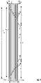
Figure 1 is a top plan view of a section of an exemplary optical-fiber ribbon in accordance with a first embodiment of this disclosure. -
Figure 2 is a top plan view of a section of an exemplary optical-fiber ribbon in accordance with a second embodiment of this disclosure. -
Figure 3 is a top plan view of a section of an exemplary optical-fiber ribbon in accordance with a third embodiment of this disclosure. -
Figure 4 is a top plan view of a section of an exemplary optical-fiber ribbon in accordance with a fourth embodiment of this disclosure. -
Figure 5 is a cross-sectional view representative of cross sections taken along line 5-5 of each ofFigures 1-4 . -
Figure 6 is a side elevation view depicting an exemplary method of making an optical-fiber ribbon in accordance with an embodiment of this disclosure. -
Figure 7 is a top pictorial view depicting a portion ofFigure 6 in accordance with a first implementation. -
Figure 8 is a top pictorial view of a section of an optical-fiber ribbon, wherein dashed lines schematically depict portions of bonding material supplied by the system ofFigure 6 . -
Figure 9 is a top pictorial view depicting a portion ofFigure 6 in accordance with a second implementation. - Various aspects and features are herein described with reference to the accompanying figures. Details are set forth to provide a thorough understanding of the present disclosure. It will be apparent, however, to those having ordinary skill in the art that the disclosed optical-fiber ribbons and methods for producing optical-fiber ribbons may be practiced or performed without some or all of these specific details. As another example, features disclosed as part of one embodiment can be used in another embodiment to yield a further embodiment. Sometimes well-known aspects are not described in detail to avoid unnecessarily obscuring the present disclosure.
- As depicted in
Figures 1-4 , an exemplary optical-fiber ribbon 1 includes a plurality n of respectively adjacent optical fibers 11 (e.g., 12, 24, or 36 optical fibers, such as 250-micron optical fibers or 200-micron optical fibers) extending in a longitudinal direction and arranged in parallel to form an optical-fiber assembly 10, which has a width w extending crosswise to a longitudinal length of the optical-fiber assembly 10. The optical-fiber ribbon 1 further includes bonding material 16 on the optical-fiber assembly 10 (e.g., deposited as adhesive beads on a major surface of the optical-fiber assembly 10, such as its upper planar surface) adhesively bonding adjacent optical fibers 11 in the optical-fiber assembly 10, the bonding material 16 repeatedly forming alternating first and second bonding-material patterns 21, 22 across the optical-fiber assembly 10 for a portion of its longitudinal length, wherein, in the same direction along the longitudinal length of the optical-fiber assembly 10: (i) the first bonding-material patterns 21 extend across the optical-fiber assembly 10 from a first outermost optical fiber 11a in the optical-fiber assembly 10 to an opposite second outermost optical fiber 11b in the optical-fiber assembly 10, and the second bonding-material patterns 22 extend across the optical-fiber from the second outermost optical fiber 11b in the optical-fiber assembly to the opposite first outermost optical fiber 11a in the optical-fiber assembly; (ii) the alternating first and second bonding-material patterns 21, 22 have respective mean lengths l1 and l2 as measured along the longitudinal length of the optical-fiber assembly 10; and (iii) the alternating first and second bonding-material patterns 21, 22 achieve recurring adhesive-free gaps 17 in which no bonding material 16 is present across the width w of the optical-fiber assembly 10 for a portion of its longitudinal length, the adhesive-free gaps 17 having a minimum length g as measured along the longitudinal length of the optical-fiber assembly, wherein g ≥ 8 x (l1 ÷ n) if l1 ≤ l2 and g ≥ 8 x (l2 ÷ n) if l2 ≤ l1. Typically, each of the first bonding-material patterns 21 has essentially the same length l1 , and each of the second bonding-material patterns 22 has essentially the same length l2 , too (e.g., the first and second bonding-material patterns - As depicted in
Figure 5 , an exemplary optical-fiber assembly 10 includes a plurality ofoptical fibers 11 arranged side-by-side such that theoptical fibers 11 are substantially parallel to one another (e.g., aligned within the optical-fiber assembly 10). Eachoptical fiber 11 may be closely spaced or contiguous with an adjacentoptical fiber 11 but typically should not cross over one another along the length of the optical-fiber assembly 10.Optical fibers 11 usually include acomponent glass fiber 12 and one or more surrounding coating layers 13. SeeFigure 5 . Those having ordinary skill in the art will understand the various kinds of primary coatings, secondary coatings, and ink layers, as well as the structures and thicknesses thereof. This application hereby cites commonly ownedU.S. Patent No. 8,265,442 for a Microbend-Resistant Optical Fiber andU.S. Patent No. 8,600,206 for a Reduced-Diameter Optical Fiber. - The optical-fiber assembly 10 (and the resulting optical-fiber ribbon 1) have a substantially planar (i.e., flattened) geometry that defines a relatively narrow height, a relatively wide width, and a substantially continuous length (e.g., over 1,000 meters, such as 5,000 meters or more). As used herein, an optical-
fiber assembly 10 as depicted inFigure 5 inherently defines an upper side (i.e., the top), a lower side (i.e., the bottom), a left edge, and a right edge. The respective upper and lower sides define the major surfaces of the optical-fiber assembly 10 (and the resulting optical-fiber ribbon 1, such as shown inFigure 1-4 ). Those having ordinary skill in the art will appreciate that flipping the optical-fiber assembly 180 degrees over its major transverse axis will reverse the top and bottom, and so the terms can be used interchangeably herein depending on the frame of reference. Similarly, those having ordinary skill in the art will appreciate that yaw rotating the optical-fiber assembly 180 degrees will reverse the right edge and left edge, and so the terms can be used interchangeably herein depending on the frame of reference. Accordingly, as used herein, terms such as "first side" and "second, opposite side" refer to the respective upper and lower sides of the optical-fiber assembly 10 (and the resulting optical-fiber ribbon), or vice versa depending on the frame of reference. - As shown in
Figure 5 , theoptical fibers 11 are arranged in parallel and respectively adjacent to each other in a plane. As such, the nominal width w of the optical-fiber assembly 10 reflects the number n and diameter d of the optical fibers (i.e., w≈n x d). Typically, each optical fiber has a substantially circular cross section, and all the optical fibers in an optical-fiber ribbon have substantially the same nominal diameter. In an exemplary embodiment, the width w of the optical-fiber assembly is between about 2 millimeters and 10 millimeters (e.g., between 2 millimeters and 6 millimeters). In practice, the optical fibers are substantially contiguous to one another, although some small gaps may exist between adjacent optical fibers. The width of the resulting optical-fiber ribbon corresponds to the width w of the optical-fiber assembly. SeeFigure 5 . - In an exemplary embodiment, each optical fiber has a diameter d of between 240 microns and 260 microns, more typically about 250 microns. Alternatively, the optical fibers may have a reduced diameter d, such as between about 180 microns and 230 microns. In an exemplary embodiment, the optical-fiber assembly includes between six and 36 optical fibers (including 6 and 36), such as between twelve and 24 optical fibers (including 12 and 24). For example, an exemplary optical-fiber ribbon formed of twelve (12) 250-micron optical fibers yields a nominal width w of 3000 microns (i.e., 3 millimeters). Similarly, an exemplary optical-fiber ribbon formed of twelve (12) 200-micron reduced-diameter optical fibers yields a nominal width w of 2400 microns (i.e., 2.4 millimeters), and an exemplary optical-fiber ribbon formed of twelve (12) 180-micron reduced-diameter optical fibers yields a nominal width w of 2160 microns (i.e., 2.16 millimeters). Accordingly, those having ordinary skill in the art will appreciate that, with respect to optical-
fiber ribbon 1 and the optical-fiber assembly 10, the figures schematically exaggerate the width relative to length, such as to illustrate the characteristics of the first and second bonding-material patterns - Typically, along the optical-
fiber assembly 10 for a portion of its longitudinal length, each first bonding-material pattern 21 immediately follows a second bonding-material pattern 22, and each second bonding-material pattern 22 immediately follows a first bonding-material pattern 21. SeeFigures 1-4 . In this regard, pitch p is the length of the recurring pattern of bonding material (e.g., deposited adhesive beads) as applied to an optical-fiber assembly (e.g., the repeating length of the alternating first and second bonding-material patterns 21, 22). In contrast, the mean length l1 of the first bonding-material patterns 21 and the mean length of the l2 of the second bonding-material patterns 22 reflect longitudinal distances covered by arrangements of bonding material (e.g., an adhesive bead or beads) from the first outermostoptical fiber 11a to the second outermostoptical fiber 11b, or vice-versa (e.g., across one width w of the optical-fiber assembly). SeeFigures 1-4 . Exemplary optical-fiber ribbons have a pitch p between about 10w and 150w as normalized to the width w of the optical-fiber ribbon 1 (e.g., about 15w-100w, such as about 20w-80w or 25w-60w). - In typical embodiments of the optical-fiber ribbon, the alternating first and second bonding-
material patterns material patterns 21 is inclusively between 90 percent and 100 percent of the mean length of the l2 of the second bonding-material patterns 22, or the mean length l2 of the second bonding-material patterns 22 is inclusively between 90 percent and 100 percent of the mean length l1 of the first bonding-material patterns 21. - In other embodiments of the optical-fiber ribbon, the alternating first and second bonding-
material patterns fiber assembly 10. In some embodiments, the mean length l1 of the first bonding-material patterns is between 10 percent and 95 percent of the mean length l2 of the second bonding-material patterns, or the mean length l2 of the second bonding-material patterns is between 10 percent and 95 percent of the mean length l1 of the first bonding-material patterns. - In another exemplary optical-
fiber ribbon 1, the alternating first and second bonding-material patterns free gaps 17 in which nobonding material 16 is present across the width w of the optical-fiber assembly 10 for a portion of its longitudinal length, the adhesive-free gaps 17 having a minimum length g as measured along the longitudinal length of the optical-fiber assembly 10, wherein g ≥ 10 x (l1 ÷ n) if l1 ≤ l2 and g ≥ 10 x (l2 ÷ n) if l2 ≤ l1. - In yet another exemplary optical-
fiber ribbon 1, the alternating first and second bonding-material patterns free gaps 17 in which nobonding material 16 is present across the width w of the optical-fiber assembly 10 for a portion of its longitudinal length, the adhesive-free gaps 17 having a minimum length g as measured along the longitudinal length of the optical-fiber assembly 10, wherein g ≥ 12 x (l1 ÷ n) if l1 ≤ l2 and g ≥ 12 x (l2 ÷ n) if l2 ≤ l1. - In yet another exemplary optical-
fiber ribbon 1, the alternating first and second bonding-material patterns free gaps 17 in which nobonding material 16 is present across the width w of the optical-fiber assembly 10 for a portion of its longitudinal length, the adhesive-free gaps 17 having a minimum length g as measured along the longitudinal length of the optical-fiber assembly 10, wherein g ≥ 16 x (l1 ÷ n) if l1 ≤ l2 and g ≥ 16 x (l2 ÷ n) if l2 ≤ l1. - In yet another exemplary optical-
fiber ribbon 1, the alternating first and second bonding-material patterns free gaps 17 in which nobonding material 16 is present across the width w of the optical-fiber assembly 10 for a portion of its longitudinal length, the adhesive-free gaps 17 having a minimum length g as measured along the longitudinal length of the optical-fiber assembly 10, wherein g ≥ 24 x (I1 ÷ n) if l1 ≤ l2 and g ≥ 24 x (l2 ÷ n) if l2 ≤ l1. - In yet another exemplary optical-
fiber ribbon 1, the optical-fiber assembly 10 includes at least four adjacentoptical fibers 11 extending in a longitudinal direction and arranged in parallel (i.e., n ≥ 4), and the alternating first and second bonding-material patterns free gaps 17 in which nobonding material 16 is present across the width w of the optical-fiber assembly 10 for a portion of its longitudinal length, the adhesive-free gaps 17 having a minimum length g as measured along the longitudinal length of the optical-fiber assembly 10, wherein g ≥ 2 x l1 if l1 ≤ l2 and g ≥ 2 x l2 if l2 ≤ l1. - In yet another exemplary optical-
fiber ribbon 1, the optical-fiber assembly 10 includes at least six adjacentoptical fibers 11 extending in a longitudinal direction and arranged in parallel (i.e., n ≥ 6), and the alternating first and second bonding-material patterns free gaps 17 in which nobonding material 16 is present across the width w of the optical-fiber assembly 10 for a portion of its longitudinal length, the adhesive-free gaps 17 having a minimum length g as measured along the longitudinal length of the optical-fiber assembly 10, wherein g ≥ (l1 + l2), such as g > (l1 + l2). - In yet another exemplary optical-
fiber ribbon 1, the alternating first and second bonding-material patterns free gaps 17 in which nobonding material 16 is present across the width w of the optical-fiber assembly 10 for a portion of its longitudinal length, the adhesive-free gaps 17 having a minimum length g as measured along the longitudinal length of the optical-fiber assembly 10, wherein g ≥ (l1 + l2) x (n ÷ (n-2)), such as wherein g > (l1 + l2) x (n ÷ (n-2)). All things being equal, the adhesive-free gaps 17 between successive first and second bonding-material patterns optical fiber - In yet another exemplary optical-
fiber ribbon 1, in the same direction along the longitudinal length of the optical-fiber assembly 10, the minimum length g of the adhesive-free gaps 17 is a first adhesive-free gap distance g1-2 between adjacent, spaced ends of successive first and second bonding-material patterns material pattern 21 and the adjacent end of the second bonding-material pattern 22 are located along the second outermostoptical fiber 11b in the optical-fiber assembly 10, wherein g1-2 ≥ 8 x ((l1 + l2) ÷ 2n) as measured along the longitudinal length of the optical-fiber assembly 10. (This exemplary embodiment bases the minimum length g on the average of the mean lengths l1 and l2 of the first and second bonding-material patterns, 21, 22.)Figure 1 similarly depicts a second adhesive-free gap distance g2-1 between adjacent, spaced ends of successive second and first bonding-material patterns material pattern 22 and the adjacent end of the first bonding-material pattern 21 are located along the first outermostoptical fiber 11a in the optical-fiber assembly 10. In a related embodiment, in the same direction along the longitudinal length of the optical-fiber assembly 10, the successive first and second bonding-material patterns optical fiber 11a in the optical-fiber assembly 10 and are spaced apart by a separation distance d1-2 , wherein d 1- 2 ≈ g1-2 + l1 + l2 as measured along the longitudinal length of the optical-fiber assembly. - As illustrated in
Figures 1-2 , the area between first and second bonding-material patterns sometimes defines a trapezoidal adhesive-free area 17 having a short base g1-2 (e.g., a first adhesive-free gap distance) along the second outermostoptical fiber 11b in the optical-fiber assembly 10 and a long base d1-2 (e.g., a separation distance) located along the first outermostoptical fiber 11a in the optical-fiber assembly 10. With respect to the bonding patterns depicted inFigure 1 , the separation distance d1-2 is noticeably shorter than the pitch p (e.g., the repeating length of the alternating first and second bonding-material patterns 21, 22). In contrast, with respect to the bonding patterns depicted inFigure 2 , the separation distance d1-2 is nearly the pitch p (e.g., the repeating length of the alternating first and second bonding-material patterns 21, 22), such that d1-2 ≈ p. - By way on non-limiting example with respect to representative 12-optical-fiber ribbons, exemplary adhesive-free gaps have a minimum length g (as measured along the longitudinal length of the optical-fiber assembly) of at least 15 millimeters, such as at least 20 millimeters to accommodate conventional alignment chucks. Typically, exemplary adhesive-free gaps have a minimum length g between about 25 millimeters and 150 millimeters, such as between about 30 millimeters and 100 millimeters (e.g., 35-75 millimeters, such as about 50 millimeters).
- With reference to
Figure 1 , an exemplary trapezoidal adhesive-free area 17 might have a short base g1-2 (e.g., a first adhesive-free gap distance) of between about 15 millimeters and 50 millimeters (e.g., about 20-25 millimeters) and a long base d1-2 (e.g., a separation distance) of between about 20 millimeters and 200 millimeters, such as between about 50 millimeters and 150 millimeters (e.g., about 70-100 millimeters). In other embodiments, the separation distance d1-2 might exceed 150 millimeters, such as 200 millimeters to 300 millimeters (e.g., about 250 millimeters). - With reference to
Figure 2 , an exemplary trapezoidal adhesive-free area 17 might have a short base g1-2 (e.g., a first adhesive-free gap distance) of between about 40 millimeters and 100 millimeters (e.g., about 50-60 millimeters) and a long base d1-2 (e.g., a separation distance) of between about 80 millimeters and 200 millimeters (e.g., about 100-125 millimeters). Here, the long base d1-2 (e.g., a separation distance) is approximately the pitch p (e.g., the repeating length of the alternating first and second bonding-material patterns 21, 22). In other embodiments, the separation distance d1-2 might exceed 200 millimeters, such as 250 millimeters to 400 millimeters (e.g., about 300 millimeters). -
Figures 1-4 depict exemplary optical-fiber ribbons, such as can be formed from an exemplary optical-fiber assembly 10 as depicted inFigure 5 , further includingbonding material 16 repeatedly forming alternating first and second bonding-material patterns fiber assembly 10 for a portion of its longitudinal length (e.g., between the optical-fiber assembly's outermost optical fibers to adhesively bond corresponding adjacent optical fibers). - In an exemplary optical-fiber ribbon, along a longitudinal portion of the optical-
fiber assembly 10, each of the first bonding-material patterns 21 respectively comprises a continuous bead of bonding material 16 (e.g., respective continuous adhesive beads between the first outermostoptical fiber 11a and the second outermostoptical fiber 11b such as depicted inFigures 1-2 ). Similarly, in an exemplary optical-fiber ribbon, along a longitudinal portion of the optical-fiber assembly 10, each of the second bonding-material patterns 22 respectively comprises a continuous bead of bonding material 16 (e.g., respective continuous adhesive beads between the second outermostoptical fiber 11b and the first outermostoptical fiber 11b such as partially depicted inFigures 1-2 ). In another exemplary embodiment, for the same portion of the optical-fiber assembly's longitudinal length, the alternating first and second bonding-material patterns that achieve recurring adhesive-free gaps having a minimum length g in which no bonding material is present across the width w of the optical-fiber assembly each respectively include only (e.g., consists of or consists essentially of) a continuous bead of bonding material. SeeFigures 1-2 . - In another exemplary optical-fiber ribbon, along a longitudinal portion of the optical-
fiber assembly 10, each of the first bonding-material patterns 21 respectively comprises a plurality of successive elongatedrectilinear beads 16 arranged lengthwise along the optical-fiber assembly 10, wherein thebeads 16 are configured to form elongated bonds between adjacentoptical fibers 11 in the optical-fiber assembly 10 (e.g., an arrangement of rectilinear adhesive beads between the first outermostoptical fiber 11a and the second outermostoptical fiber 11b such as depicted inFigures 3-4 ). Similarly, in an exemplary optical-fiber ribbon, along a longitudinal portion of the optical-fiber assembly 10, each of the second bonding-material patterns 22 respectively comprises a plurality of successive elongatedrectilinear beads 16 arranged lengthwise along the optical-fiber assembly 10, wherein thebeads 16 are configured to form elongated bonds between adjacentoptical fibers 11 in the optical-fiber assembly 10 (e.g., an arrangement of rectilinear adhesive beads between the second outermostoptical fiber 11b and the first outermostoptical fiber 11a such as depicted inFigures 3-4 ). In another exemplary embodiment, for the same portion of the optical-fiber assembly's longitudinal length, the alternating first and second bonding-material patterns that achieve recurring adhesive-free gaps having a minimum length g in which no bonding material is present across the width w of the optical-fiber assembly each respectively include only (e.g., consists of or consists essentially of) a plurality of successive elongated rectilinear beads arranged lengthwise along the optical-fiber assembly, wherein the beads are configured to form elongated bonds between adjacent optical fibers in the optical-fiber assembly. SeeFigures 3-4 . - During manufacturing, the bonding material may be applied to the optical-fiber assembly as a continuous bead or as discontinuous beads, such as disclosed in commonly assigned
U.S. Patent No. 10,782,495 - An exemplary method for applying either a continuous bead of bonding material or discontinuous beads of bonding material to an optical-fiber assembly in a way that facilitates faster line speeds during the manufacturing of optical-fiber ribbons is disclosed in commonly assigned
U.S. Patent Application No. 16/683,827 for an Optical-Fiber Ribbon, now U.S. Patent No.__________. - In another aspect, the invention embraces a method of producing an optical-fiber ribbon. As shown in the process schematic depicted in
Figures 6 (processing from right to left), a plurality n of optical fibers 11 (e.g., 12 or 24 reduced-diameter optical fibers) are arranged into a longitudinal optical-fiber assembly 10 having a width w extending crosswise to a longitudinal length of the optical-fiber assembly. For example, a plurality ofoptical fibers 11 are introduced (e.g., fed into a die 24) to provide a longitudinal optical-fiber assembly 10 in which the plurality ofoptical fibers 11 are substantially parallel and respectively adjacent to each other. Typically, the longitudinal optical-fiber assembly 10 is a loose arrangement of substantially parallel optical fibers with no bonding between the optical fibers and having interstices or grooves between adjacent optical fibers. When employing an aggregatingdie 24 to align the optical fibers, the entry speed of the loose optical fibers is the same as the exit speed of the longitudinal optical-fiber assembly. - During processing, the longitudinal optical-
fiber assembly 10 advances at linear velocity v, typically at a linear speed greater than 150 meters per minute (e.g., greater than 200 meters per minute, such as greater than 300 meters per minute). In some exemplary embodiments, the longitudinal optical-fiber assembly 10 advances at linear velocity v between 400 and 700 meters per minute (e.g., between about 500 and 600 meters per minute). - As the optical-
fiber assembly 10 passes near (e.g., beneath) a dispenser unit 25 (or similar dispensing device), bonding material (e.g., a curable adhesive) is applied to the optical-fiber assembly 10 to adhesively bond adjacentoptical fibers 11 in the optical-fiber assembly. For example, the bonding material may be dispensed as a continuous adhesive bead (or a plurality of discontinuous beads) via a dispensingnozzle 26 to a major surface of the optical-fiber assembly 10 (e.g., its upper planar surface). Typically, thedispenser 25 and/or the dispensingnozzle 26 apply bonding material to eachoptical fiber 11 in the optical-fiber assembly 10 to bond the optical-fibers 11 into an optical-fiber ribbon 1. - Exemplary process embodiments, described herein, include applying bonding material to the optical-fiber assembly (e.g., a major surface, such as its upper planar surface) to adhesively bond adjacent optical fibers in the optical-fiber assembly, wherein the dispenser repeatedly moves an amplitude Ad measured crosswise to the longitudinal length of the optical-fiber assembly such that the dispenser's amplitude Ad exceeds the optical-fiber assembly's width w (e.g., an "overshooting" technique). Thereafter, the optical-fiber assembly with an adhesive bead is passed through a curing
station 28 for curing the bonding material (e.g., a curable adhesive, such as curable ultraviolet (UV) resins). SeeFigures 5-6 . - In some exemplary process embodiments, the
dispenser 25 and/or the dispensing nozzle 26 (or other dispensing device) oscillate in a direction transverse to the longitudinal direction (i.e., in the width direction) of the optical-fiber assembly, and the optical-fiber assembly moves in the longitudinal direction, such as via areel 29. The tip of the dispenser 25 (e.g., the dispensing nozzle 26) may oscillate (e.g., vibrate) in a transverse direction at a high frequency, such as between about 100 Hz and 200 Hz. In an exemplary process embodiment, the dispensingnozzle 26 may deliver liquid bonding material in fine droplets to the advancing optical-fiber assembly 10. Because of surface tension, the liquid bonding material - if provided in sufficient droplets at a sufficient frequency - will flow together to form adhesive beads (e.g., elongated beads). - In an exemplary process embodiment, the
dispenser 25 and/or the dispensingnozzle 26 move crosswise substantially corresponding to the width w of the longitudinal optical-fiber assembly 10. In this way, the bonding material is applied as an adhesive bead across at least one major surface of the optical-fiber assembly (e.g., in a pattern on the upper planar surface substantially across the width of the optical-fiber assembly). As will be understood by those having ordinary skill in the art, providing an adhesive bead "substantially across the width" of the optical-fiber assembly bonds adjacent optical fibers to yield an optical-fiber ribbon (e.g., the adhesive deposition patterns extend to the outermost opposite optical fibers in the optical-fiber assembly). - In a related process embodiment, the
dispenser 25 and/or the dispensingnozzle 26 move crosswise substantially corresponding to the lateral distance (w - 2d) between the two outermost optical fibers. As will be understood by those having ordinary skill in the art, this lateral distance (w- 2d) is the separation between the outermost grooves in the optical-fiber assembly (e.g., as defined by the respective interfaces of each outermost optical fiber and its respective adjacent optical fiber). SeeFigure 5 . As used herein, terms like "substantially corresponding to the width" and "substantially corresponding to the lateral distance" refer to the movement of a dispensing nozzle and/or the corresponding adhesive deposition patterns, which typically extend to the outermost opposite optical fibers in the optical-fiber assembly (e.g., opposite edge portions of the optical-fiber assembly). - Typically, the adhesive beads bonding adjacent optical fibers in the optical-fiber assembly form a regular pattern (continuous or discontinuous) across the width of the optical-fiber assembly, such as a zigzag-like pattern, a sawtooth-like pattern, or a sinusoidal-like pattern having a peak-to-valley amplitude substantially between (i) the lateral distance between the two outermost optical fibers (w - 2d) and (ii) the width w of the optical-fiber assembly. (Some excess bonding material may be present outside one or both outermost optical fibers in the optical-fiber ribbon.) In some exemplary process embodiments, the dispensing nozzle may pause when positioned above grooves in the optical-fiber assembly to deposit bonding material as longitudinal, rectilinear adhesive beads within the respective grooves (e.g., grooves between contiguous optical fibers).
- In process embodiments in which the
dispenser 25 and/or thedispenser nozzle 26 move crosswise substantially corresponding to the (i) the lateral distance between the two outermost optical fibers (w - 2d) and (ii) the width w of the optical-fiber assembly, the application of bonding material periodically or intermittently stops (e.g., while the longitudinal optical-fiber assembly continues to advance at linear velocity v) to achieve recurring adhesive-free gaps in which no bonding material is present across the width w of the optical-fiber assembly for a portion of its longitudinal length. In this way, the intermittent application of bonding material to the optical-fiber assembly achieves exemplary optical-fiber ribbons, such as those depicted inFigures 1-4 . - In an alternative process embodiment, the
dispenser 25 and/or the dispensingnozzle 26 move crosswise but "overshoot" the width w of the longitudinal optical-fiber assembly 10. That is, thedispenser 25 and/or dispensingnozzle 26 move an amplitude Ad measured crosswise to the longitudinal length of the optical-fiber assembly 10, wherein the dispenser's amplitude Ad exceeds the optical-fiber assembly's width w. In this way, the bonding material is applied as anadhesive bead 16 across at least one major surface of the optical-fiber assembly (e.g., in a pattern on the upper planar surface substantially across the width of the optical-fiber assembly) to bond adjacent optical fibers. Thedispenser 25 and/or the dispensingnozzle 26 apply bonding material to eachoptical fiber 11 in the optical-fiber assembly 10 to yield an optical-fiber ribbon in which the adhesive deposition patterns extend to the outermost opposite optical fibers in the optical-fiber assembly. For example, in many process embodiments, thedispenser unit 25 repeatedly moves across the width w of the optical-fiber assembly 10 beyond both a first outermostoptical fiber 11a in the optical-fiber assembly and an opposite second outermostoptical fiber 11b in the optical-fiber assembly to apply bonding material to eachoptical fiber 11 in the optical-fiber assembly 10. More generally, thedispenser 25 and/or the dispensingnozzle 26 may overshoot both edges of the optical-fiber assembly (e.g., the first outermostoptical fiber 11a and the opposite second outermostoptical fiber 11b in the optical-fiber assembly 10) or only one edge of the optical-fiber assembly (e.g., either the first outermostoptical fiber 11a or the opposite second outermostoptical fiber 11b in the optical-fiber assembly 10). See e.g.,Figure 5 . - This "overshooting" technique can be advantageous because it can produce an optical-fiber ribbon having recurring adhesive-free gaps (e.g., areas in which essentially no bonding material is present across the width w of the optical-fiber assembly for a portion of its longitudinal length) while the bonding material is applied (e.g., continuously applied) to the optical-fiber assembly. More generally, the "overshooting" technique can yield adhesive beads that bond adjacent optical fibers in regular patterns (continuous or discontinuous) across the width of the optical-fiber assembly, such as a zigzag-like pattern, a sawtooth-like pattern, or a sinusoidal-like pattern having a peak-to-valley amplitude substantially between (i) the lateral distance between the two outermost optical fibers (w - 2d) and (ii) the width w of the optical-fiber assembly. Continuous beads typically extend across the full width w of the optical-fiber assembly. (As noted, some excess bonding material may be present outside one or both outermost optical fibers in the optical-fiber ribbon.)
- In one process embodiment, the
dispenser 25 and/or dispensingnozzle 26 continuously reciprocate an amplitude Ad across the width w of the optical-fiber assembly. This uninterrupted reciprocation can produce continuous adhesive beads (e.g., zigzag-like patterns or sinusoidal-like patterns) between the outermost optical fibers in the optical-fiber assembly, such as depicted inFigures 1-2 . See alsoFigures 7-8 . - By way of illustration,
Figure 7 depicts a process embodiment in which the dispensingnozzle 26 linearly reciprocates across the optical-fiber assembly (e.g., moves side-to-side crosswise to the longitudinal length of the optical-fiber assembly with an amplitude Ad exceeding the optical-fiber assembly's width w). This kind of "overshooting" reciprocation can yield an optical-fiber ribbon 1, such as schematically depicted inFigure 8 , having recurring adhesive-free gaps in which no bonding material is present across the width w of the optical-fiber assembly for a portion of its longitudinal length. -
Figure 9 depicts an alternative process embodiment in which the dispensing nozzle 26 (or other dispensing device) revolves around a central axis at a cyclical frequency r (e.g., moves in a circular or elliptical motion over the optical-fiber assembly 10 with an amplitude Ad exceeding the optical-fiber assembly's width w). In a related process embodiment, the dispensingnozzle 26 revolves around a central axis that is centrally positioned to substantially intersect the optical-fiber assembly's midline (w/2) (e.g., via a continuous or intermittent dispenser movement) to apply bonding material to each optical fiber in the optical-fiber assembly (e.g., while overshooting both edges of the optical-fiber assembly). For example, the depositedadhesive bead 16 across the width of the optical-fiber assembly may have a distorted sinusoidal pattern repeatedly forming (i) peaks at one edge portion of the optical-fiber assembly and (ii) valleys at an opposite edge portion of the optical-fiber assembly. Typically, these distorted sinusoidal peaks and distorted sinusoidal valleys have different respective shapes. - In related process embodiments, the
dispenser 25 and/or the dispensing nozzle 26 (or other dispensing device) revolve in a plane parallel to a planar optical-fiber assembly 10. This has been observed to promote faster line speeds during the manufacturing of a continuously or intermittently bonded optical-fiber ribbon 1, such as an optical-fiber ribbon with a distorted sinusoidal pattern of bonding material. In this regard, anexemplary dispensing nozzle 26 is made of a capillary tube at the center of a metallic sleeve that is revolving in a substantially circular orbit via a servomotor (e.g., using belt-pulley system). Such a configuration reduces undesirable vibrations, which can be caused by the linear motion of a conventional reciprocating crank shaft as typically used with reciprocating nozzles, and avoids overlapping and/or uneven distribution of bonding material, which can occur using a conventional reciprocating crank shaft. Indeed, it has been observed that the use of a revolving nozzle helps to achieve linear velocities v between 400 and 700 meters per minute, which is about 4-5 times greater than is possible with a conventional reciprocating-crank-shaft system. For example, the linear velocity v of the optical-fiber assembly and the cyclical frequency r of the dispensingnozzle 26 can be controlled to achieve a pitch p (e.g., v/r) of at least about 50 millimeters, such as between 50 millimeters and 400 millimeters (e.g., between about 75 and 300 millimeters, such as 100-200 millimeters or 120-175 millimeters, for a 12-optical-fiber ribbon). As noted, exemplary optical-fiber ribbons may have a pitch p between about 10w and 150w as normalized to the width w of the optical-fiber ribbon 1 (e.g., about 30w-65w, such as about 35w-50w or 40w-60w, for an exemplary sinusoidal-like deposition pattern of adhesive). - In another exemplary process embodiment, the
dispenser 25 and/or dispensingnozzle 26 reciprocate an amplitude Ad in intermittent steps across the width w of the optical-fiber assembly (e.g., via linear reciprocation or revolution around a central axis). For example, the dispensing nozzle may pause when positioned above grooves in the optical-fiber assembly to deposit bonding material as longitudinal, rectilinear adhesive beads within the respective grooves (e.g., grooves between contiguous optical fibers). Such intermittent reciprocation can produce rectilinear adhesive beads (e.g., rectilinear-bead patterns) between the outermost optical fibers in the optical-fiber assembly, such as depicted inFigures 3-4 . - By way of background and illustration, the respective cross-sectional areas of exemplary adhesive beads can be approximated by 125-micron equilateral-triangle sides for 250-micron optical fibers (e.g., about 0.0068 mm2) and by 100-micron equilateral-triangle sides for 200-micron optical fibers (e.g., about 0.0043 mm2). With a +/- 20 percent estimation of bead dimensions, the respective ranges for cross-sectional areas of the beads can be approximated by 100-micron to 150-micron equilateral-triangle sides for the 250-micron optical fibers (e.g., between about 0.0043 mm2 and 0.0097 mm2) and by 80-micron to 120-micron equilateral-triangle sides for the 200-micron optical fibers (e.g., between about 0.0028 mm2 and 0.0062 mm2).
- In accordance with the foregoing, it is within the scope of the present disclosure to have either one substantially continuous adhesive bead or a series of discontinuous beads that secure (e.g., affix) the optical fibers within the optical-fiber ribbon. In an exemplary embodiment, the adhesive bead(s) are arranged on only one side of the optical-fiber assembly (i.e., a first side). For example, the bead(s) are arranged only on one major surface of the optical-fiber assembly, typically its upper surface (i.e., when the optical fibers are arranged in a ribbon-like manner rather than rolled up). As noted, the optical-fiber assembly can be viewed as a ribbon-like assembly defining an upper surface, a lower surface, and two side edges. The upper and lower surfaces (i.e., the respective major surfaces) are not completely flat, because they are formed of a substantially parallel arrangement of optical fibers. As such, the upper and lower surfaces have parallel longitudinal grooves between adjacent optical fibers. Those having ordinary skill in the art will understand the optical fibers may not be perfectly parallel but rather substantially parallel in practice.
- As discussed, in exemplary optical-fiber ribbons according to the present invention, bonding material adhesively bonds adjacent optical fibers in an optical-fiber assembly. Two such optical-fiber ribbons may be aligned and joined using a mass-fusion splicing machine. For example, corresponding 12-fiber optical-fiber ribbons may be positioned in respective 12-fiber alignment chucks and, after heat stripping, cleaning, and cleaving, the two optical-fiber ribbons may be spliced at once (e.g., the corresponding optical fibers can be simultaneously butt-spliced end-to-end in the mass-fusion splicing machine).
- The optical-fiber ribbon according to the present invention may be used to form optical-fiber-cable units and optical-fiber cables. An exemplary optical-fiber-cable unit has 24 ribbons of twelve optical fibers each. Such an optical-fiber-cable unit packs 288 optical fibers into a high optical-fiber density. Accordingly, in another inventive aspect, the present invention embraces an optical-fiber-cable unit including one or more optical-fiber ribbons (also according to the present invention) surrounded by a polymeric sheath. The present invention further embraces an optical-fiber cable including one or more of the optical-fiber ribbons or optical-fiber-cable units according to the present invention.
- To supplement the present disclosure, this application cites the following commonly assigned patents, patent application publications, and patent applications:
U.S. Patent No. 7,623,747 for a Single Mode Optical Fiber,U.S. Patent No. 7,889,960 for a Bend-Insensitive Single-Mode Optical Fiber,U.S. Patent No. 8,145,025 for a Single-Mode Optical Fiber Having Reduced Bending Losses;U.S. Patent No. 8,265,442 for a Microbend-Resistant Optical Fiber,U.S. Patent No. 8,600,206 for a Reduced-Diameter Optical Fiber,U.S. Patent No. 10,185,105 U.S. Patent No. 10,782,495 PCT/EP2017/067454 (filed July 11, 2017 WO 2019/011417 A1 and as U.S. Patent Application Publication No.US2020/0271879 A1 ); International Application No.PCT/EP2018/050898 (filed January 15, 2018 WO 2019/137627 A1 ); International Application No.PCT/EP2018/050899 (filed January 15, 2018 WO 2019/137628 A1 );U.S. Patent Application No. 16/856,268 (filed April 23, 2020 US2020/0386961 A1 ); ); and U.S. Patent Application No. __________ for an Optical-Fiber Ribbon with Spaced Optical-Fiber Units (concurrently filed December 22, 2020). - Other variations of the disclosed embodiments can be understood and effected by those of ordinary skill in the art in practicing the present invention by studying the drawings, the disclosure, and the appended claims. In the claims, the word "comprising" does not exclude other elements or steps, and the indefinite article "a" or "an" does not exclude a plurality. Unless otherwise specified, numerical ranges are intended to include the endpoints.
- It is within the scope of this disclosure for one or more of the terms "substantially," "about," "approximately," and/or the like, to qualify each adjective and adverb of the foregoing disclosure, to provide a broad disclosure. As an example, it is believed those of ordinary skill in the art will readily understand that, in different implementations of the features of this disclosure, reasonably different engineering tolerances, precision, and/or accuracy may be applicable and suitable for obtaining the desired result. Accordingly, it is believed those of ordinary skill will readily understand usage herein of the terms such as "substantially," "about," "approximately," and the like.
- The use of the term "and/or" includes any and all combinations of one or more of the associated listed items. The figures are schematic representations and so are not necessarily drawn to scale. Unless otherwise noted, specific terms have been used in a generic and descriptive sense and not for purposes of limitation.
-
- 1. An optical-fiber ribbon, comprising:
- (i) a plurality n of respectively adjacent optical fibers extending in a longitudinal direction and arranged in parallel to form an optical-fiber assembly having a width w extending crosswise to a longitudinal length of the optical-fiber assembly; and
- (ii) bonding material on the optical-fiber assembly adhesively bonding adjacent optical fibers in the optical fiber assembly, the bonding material repeatedly forming alternating first and second bonding-material patterns across the optical-fiber assembly for a portion of its longitudinal length, wherein, in the same direction along the longitudinal length of the optical fiber assembly:
- the first bonding-material patterns extend across the optical-fiber assembly from a first outermost optical fiber in the optical-fiber assembly to an opposite second outermost optical fiber in the optical fiber assembly, and the second bonding-material patterns extend across the optical-fiber from the second outermost optical fiber in the optical-fiber assembly to the opposite first outermost optical fiber in the optical-fiber assembly,
- the alternating first and second bonding-material patterns have respective mean lengths l1 and l2 as measured along the longitudinal length of the optical-fiber assembly, and
- the alternating first and second bonding-material patterns achieve recurring adhesive free gaps in which no bonding material is present across the width w of the optical-fiber assembly for a portion of its longitudinal length, the adhesive-free gaps having a minimum length g as measured along the longitudinal length of the optical-fiber assembly, wherein g ≥ 8 x (l1 ÷ n) if l1 ≤ l2 and g ≥ 8 x (l2 ÷ n) if l2 ≤ l1.
- 2. The optical-fiber ribbon according to
Clause 1, wherein the alternating first and second bonding-material patterns achieve recurring adhesive free gaps in which no bonding material is present across the width w of the optical-fiber assembly for a portion of its longitudinal length, the adhesive-free gaps having a minimum length g as measured along the longitudinal length of the optical-fiber assembly, wherein g ≥ 16 x (l1 ÷ n) if l1 ≤ l2 and g ≥ 16 x (l2 ÷ n) if l2 ≤ l1. - 3. The optical-fiber ribbon according to
Clause 1, wherein the optical-fiber assembly comprises at least four adjacent optical fibers extending in a longitudinal direction and arranged in parallel, wherein n ≥ 4; and the alternating first and second bonding-material patterns achieve recurring adhesive free gaps in which no bonding material is present across the width w of the optical-fiber assembly for a portion of its longitudinal length, the adhesive-free gaps having a minimum length g as measured along the longitudinal length of the optical-fiber assembly, wherein g ≥ 2 x l1 if l1 ≤ l2 and g ≥ 2 x l2 if l2 ≤ l1. - 4. The optical-fiber ribbon according to
Clause 1, wherein the optical-fiber assembly comprises at least six adjacent optical fibers extending in a longitudinal direction and arranged in parallel, wherein n ≥ 6; and the alternating first and second bonding-material patterns achieve recurring adhesive free gaps in which no bonding material is present across the width w of the optical-fiber assembly for a portion of its longitudinal length, the adhesive-free gaps having a minimum length g as measured along the longitudinal length of the optical-fiber assembly, wherein g ≥ (l1 + l2). - 5. The optical-fiber ribbon according to
Clause 1, wherein the alternating first and second bonding-material patterns achieve recurring adhesive free gaps in which no bonding material is present across the width w of the optical-fiber assembly for a portion of its longitudinal length, the adhesive-free gaps having a minimum length g as measured along the longitudinal length of the optical-fiber assembly, wherein g ≥ (l1 + l2) x (n ÷ (n-2)). - 6. The optical-fiber ribbon according to
Clause 1, wherein, in the same direction along the longitudinal length of the optical-fiber assembly, the minimum length g of the adhesive-free gaps is a first adhesive-free gap distance g1-2 between adjacent, spaced ends of successive first and second bonding-material patterns whereby g = g1-2 , wherein both the adjacent end of the first bonding material pattern and the adjacent end of the second bonding-material pattern are located along the second outermost optical fiber in the optical fiber assembly, wherein g1-2 ≥ 8 x ((l1 + l2) ÷ 2n) as measured along the longitudinal length of the optical-fiber assembly. - 7. The optical-fiber ribbon according to Clause 6, wherein, in the same direction along the longitudinal length of the optical-fiber assembly, the successive first and second bonding material patterns have opposite, adjacent ends located along the first outermost optical fiber in the optical fiber assembly and are spaced apart by a separation distance d1-2, wherein d1-2 ≈ g1-2 + l1 + l2 as measured along the longitudinal length of the optical-fiber assembly.
- 8. The optical-fiber ribbon according to
Clause 1, wherein the mean length l1 of the first bonding-material patterns is inclusively between 90 percent and 100 percent of the mean length of the l2 of the second bonding-material patterns; or the mean length l2 of the second bonding-material patterns is inclusively between 90 percent and 100 percent of the mean length l1 of the first bonding-material patterns. - 9. The optical-fiber ribbon according to
Clause 1, wherein the mean length l1 of the first bonding-material patterns is between 10 percent and 95 percent of the mean length l2 of the second bonding-material patterns; or the mean length l2 of the second bonding-material patterns is between 10 percent and 95 percent of the mean length l1 of the first bonding-material patterns. - 10. The optical-fiber ribbon according to
Clause 1, wherein, along a longitudinal portion of the optical-fiber assembly, each of the first bonding material patterns respectively comprises a continuous bead of bonding material. - 11. The optical-fiber ribbon according to
Clause 10, wherein, along a longitudinal portion of the optical-fiber assembly, each of the second bonding material patterns respectively comprises a continuous bead of bonding material. - 12. The optical-fiber ribbon according to
Clause 1, wherein, for a portion of the optical fiber assembly's longitudinal length, the alternating first and second bonding-material patterns that achieve recurring adhesive free gaps having a minimum length g in which no bonding material is present across the width w of the optical-fiber assembly each respectively consists essentially of a continuous bead of bonding material. - 13. The optical-fiber ribbon according to
Clause 1, wherein, along a longitudinal portion of the optical-fiber assembly, each of the first bonding material patterns respectively comprises a plurality of successive rectilinear beads arranged lengthwise along the optical-fiber assembly, wherein the beads are configured to form elongated bonds between adjacent optical fibers in the optical-fiber assembly. - 14. The optical-fiber ribbon according to
Clause 13, wherein, along a longitudinal portion of the optical-fiber assembly, each of the second bonding material patterns respectively comprises a plurality of successive rectilinear beads arranged lengthwise along the optical-fiber assembly, wherein the beads are configured to form elongated bonds between adjacent optical fibers in the optical-fiber assembly. - 15. The optical-fiber ribbon according to
Clause 1, wherein, for a portion of the optical fiber assembly's longitudinal length, the alternating first and second bonding-material patterns that achieve recurring adhesive free gaps having a minimum length g in which no bonding material is present across the width w of the optical-fiber assembly each respectively consists essentially of a plurality of successive rectilinear beads arranged lengthwise along the optical-fiber assembly, wherein the beads are configured to form elongated bonds between adjacent optical fibers in the optical-fiber assembly. - 16. The optical-fiber ribbon according to
Clause 1, wherein, along the optical-fiber assembly for a portion of its longitudinal length, each first bonding-material pattern immediately follows a second bonding-material pattern, and each second bonding material pattern immediately follows a first bonding-material pattern. - 17. A method of making an optical-fiber ribbon, comprising:
- (i) arranging a plurality n of optical fibers into a longitudinal optical-fiber assembly having width w extending crosswise to a longitudinal length of the optical-fiber assembly, wherein the optical fibers are parallel and respectively adjacent to each other;
- (ii) advancing the longitudinal optical-fiber assembly at linear velocity v; and
- (iii) applying bonding material to the optical-fiber assembly via a dispenser to adhesively bond adjacent optical fibers in the optical fiber assembly, wherein the dispenser repeatedly moves an amplitude Ad measured crosswise to the longitudinal length of the optical fiber assembly, wherein the dispenser's amplitude Ad exceeds the optical-fiber assembly's width w.
- 18. The method according to
Clause 17, wherein the dispenser continuously reciprocates at amplitude Ad across the width w of the optical fiber assembly. - 19. The method according to
Clause 17, wherein the dispenser reciprocates at amplitude Ad in intermittent steps across the width w of the optical fiber assembly. - 20. The method according to
Clause 17, wherein the dispenser revolves around a central axis at a cyclical frequency r. - 21. The method according to
Clause 17, comprising continuously applying bonding material to the optical-fiber assembly via a dispensing nozzle while the dispensing nozzle revolves around a central axis that is centrally positioned to substantially intersect the optical fiber assembly's midline (w/2), wherein the dispensing nozzle applies bonding material to each optical fiber in the optical fiber assembly. - 22. The method according to
Clause 17, wherein the dispenser repeatedly moves across the width w of the optical fiber assembly beyond both a first outermost optical fiber in the optical fiber assembly and an opposite second outermost optical fiber in the optical-fiber assembly to apply bonding material to each optical fiber in the optical fiber assembly. - While various aspects, features, and embodiments have been disclosed herein, other aspects, features, and embodiments will be apparent to those having ordinary skill in the art. The various disclosed aspects, features, and embodiments are for purposes of illustration and are not intended to be limiting. It is intended that the scope of the present invention includes at least the following claims and their equivalents.
Claims (16)
- An optical-fiber ribbon, comprising:(i) a plurality n of respectively adjacent optical fibers extending in a longitudinal direction and arranged in parallel to form an optical-fiber assembly having a width w extending crosswise to a longitudinal length of the optical-fiber assembly; and(ii) bonding material on the optical-fiber assembly adhesively bonding adjacent optical fibers in the optical-fiber assembly, the bonding material repeatedly forming alternating first and second bonding-material patterns across the optical-fiber assembly for a portion of its longitudinal length, wherein, in the same direction along the longitudinal length of the optical-fiber assembly:the first bonding-material patterns extend across the optical-fiber assembly from a first outermost optical fiber in the optical-fiber assembly to an opposite second outermost optical fiber in the optical-fiber assembly, and the second bonding-material patterns extend across the optical-fiber from the second outermost optical fiber in the optical-fiber assembly to the opposite first outermost optical fiber in the optical-fiber assembly,the alternating first and second bonding-material patterns have respective mean lengths l1 and l2 as measured along the longitudinal length of the optical-fiber assembly, andthe alternating first and second bonding-material patterns achieve recurring adhesive-free gaps in which no bonding material is present across the width w of the optical-fiber assembly for a portion of its longitudinal length, the adhesive-free gaps having a minimum length g as measured along the longitudinal length of the optical-fiber assembly, wherein g ≥ 8 x (l1 ÷ n) if l1 ≤ l2 and g ≥ 8 x (l2 ÷ n) if l2 ≤ l1, preferably wherein g ≥ 16 x (l1 ÷ n) if l1 ≤ l2 and g ≥ 16 x (l2 ÷ n) if l2 ≤ l1, more preferably wherein g ≥ (l1 + l2) x (n ÷ (n-2)).
- The optical-fiber ribbon according to Claim 1, wherein:the optical-fiber assembly comprises at least four adjacent optical fibers extending in a longitudinal direction and arranged in parallel, wherein n ≥ 4; andthe alternating first and second bonding-material patterns achieve recurring adhesive-free gaps in which no bonding material is present across the width w of the optical-fiber assembly for a portion of its longitudinal length, the adhesive-free gaps having a minimum length g as measured along the longitudinal length of the optical-fiber assembly, wherein g ≥ 2 x l1 if l1 ≤ l2 and g ≥ 2 x l2 if l2 ≤ l1.
- The optical-fiber ribbon according to Claim 1, wherein:the optical-fiber assembly comprises at least six adjacent optical fibers extending in a longitudinal direction and arranged in parallel, wherein n ≥ 6; andthe alternating first and second bonding-material patterns achieve recurring adhesive-free gaps in which no bonding material is present across the width w of the optical-fiber assembly for a portion of its longitudinal length, the adhesive-free gaps having a minimum length g as measured along the longitudinal length of the optical-fiber assembly, wherein g ≥ (l1 + l2).
- The optical-fiber ribbon according to Claim 1, wherein, in the same direction along the longitudinal length of the optical-fiber assembly, the minimum length g of the adhesive-free gaps is a first adhesive-free gap distance g1-2 between adjacent, spaced ends of successive first and second bonding-material patterns whereby g = g1-2 , wherein both the adjacent end of the first bonding-material pattern and the adjacent end of the second bonding-material pattern are located along the second outermost optical fiber in the optical-fiber assembly, wherein g1-2 ≥ 8 x ((l1 + l2) ÷ 2n) as measured along the longitudinal length of the optical-fiber assembly.
- The optical-fiber ribbon according to Claim 4, wherein, in the same direction along the longitudinal length of the optical-fiber assembly, the successive first and second bonding-material patterns have opposite, adjacent ends located along the first outermost optical fiber in the optical-fiber assembly and are spaced apart by a separation distance d1-2 , wherein
d1-2 ≈ g1-2 + l1 + l2 as measured along the longitudinal length of the optical-fiber assembly. - The optical-fiber ribbon according to Claim 1, wherein:the mean length l1 of the first bonding-material patterns is inclusively between 90 percent and 100 percent of the mean length of the l2 of the second bonding-material patterns; orthe mean length l2 of the second bonding-material patterns is inclusively between 90 percent and 100 percent of the mean length l1 of the first bonding-material patterns.
- The optical-fiber ribbon according to Claim 1, wherein:the mean length l1 of the first bonding-material patterns is between 10 percent and 95 percent of the mean length l2 of the second bonding-material patterns; orthe mean length l2 of the second bonding-material patterns is between 10 percent and 95 percent of the mean length l1 of the first bonding-material patterns.
- The optical-fiber ribbon according to Claim 1, wherein, along a longitudinal portion of the optical-fiber assembly, each of the first bonding-material patterns respectively comprises a continuous bead of bonding material, preferably wherein, along a longitudinal portion of the optical-fiber assembly, each of the first bonding-material patterns and each of the second bonding-material patterns respectively comprises a continuous bead of bonding material.
- The optical-fiber ribbon according to Claim 1, wherein, for a portion of the optical-fiber assembly's longitudinal length, the alternating first and second bonding-material patterns that achieve recurring adhesive-free gaps having a minimum length g in which no bonding material is present across the width w of the optical-fiber assembly each respectively consists essentially of a continuous bead of bonding material.
- The optical-fiber ribbon according to Claim 1, wherein, along a longitudinal portion of the optical-fiber assembly, each of the first bonding-material patterns respectively comprises a plurality of successive rectilinear beads arranged lengthwise along the optical-fiber assembly, wherein the beads are configured to form elongated bonds between adjacent optical fibers in the optical-fiber assembly, preferably wherein, along a longitudinal portion of the optical-fiber assembly, each of the first bonding-material patterns and each of the second bonding-material patterns respectively comprises a plurality of successive rectilinear beads arranged lengthwise along the optical-fiber assembly, wherein the beads are configured to form elongated bonds between adjacent optical fibers in the optical-fiber assembly.
- The optical-fiber ribbon according to Claim 1, wherein, for a portion of the optical-fiber assembly's longitudinal length, the alternating first and second bonding-material patterns that achieve recurring adhesive-free gaps having a minimum length g in which no bonding material is present across the width w of the optical-fiber assembly each respectively consists essentially of a plurality of successive rectilinear beads arranged lengthwise along the optical-fiber assembly, wherein the beads are configured to form elongated bonds between adjacent optical fibers in the optical-fiber assembly.
- The optical-fiber ribbon according to Claim 1, wherein, along the optical-fiber assembly for a portion of its longitudinal length, each first bonding-material pattern immediately follows a second bonding-material pattern, and each second bonding-material pattern immediately follows a first bonding-material pattern.
- A method of making an optical-fiber ribbon, comprising:(i) arranging a plurality n of optical fibers into a longitudinal optical-fiber assembly having width w extending crosswise to a longitudinal length of the optical-fiber assembly, wherein the optical fibers are parallel and respectively adjacent to each other;(ii) advancing the longitudinal optical-fiber assembly at linear velocity v; and(iii) applying bonding material to the optical-fiber assembly via a dispenser to adhesively bond adjacent optical fibers in the optical-fiber assembly, wherein the dispenser repeatedly moves an amplitude Ad measured crosswise to the longitudinal length of the optical-fiber assembly, wherein the dispenser's amplitude Ad exceeds the optical-fiber assembly's width w.
- The method according to Claim 13, wherein the dispenser continuously reciprocates at amplitude Ad across the width w of the optical-fiber assembly, wherein the dispenser reciprocates at amplitude Ad in intermittent steps across the width w of the optical-fiber assembly, or wherein the dispenser revolves around a central axis at a cyclical frequency r.
- The method according to Claim 13, comprising continuously applying bonding material to the optical-fiber assembly via a dispensing nozzle while the dispensing nozzle revolves around a central axis that is centrally positioned to substantially intersect the optical-fiber assembly's midline (w/2), wherein the dispensing nozzle applies bonding material to each optical fiber in the optical-fiber assembly.
- The method according to Claim 13, wherein the dispenser repeatedly moves across the width w of the optical-fiber assembly beyond both a first outermost optical fiber in the optical-fiber assembly and an opposite second outermost optical fiber in the optical-fiber assembly to apply bonding material to each optical fiber in the optical-fiber assembly.
Applications Claiming Priority (1)
| Application Number | Priority Date | Filing Date | Title |
|---|---|---|---|
| US17/130,589 US11460652B2 (en) | 2020-12-22 | 2020-12-22 | Optical-fiber ribbon with adhesive-free gaps |
Publications (1)
| Publication Number | Publication Date |
|---|---|
| EP4020048A1 true EP4020048A1 (en) | 2022-06-29 |
Family
ID=78828085
Family Applications (1)
| Application Number | Title | Priority Date | Filing Date |
|---|---|---|---|
| EP21213420.9A Pending EP4020048A1 (en) | 2020-12-22 | 2021-12-09 | Optical-fiber ribbon with adhesive-free gaps |
Country Status (5)
| Country | Link |
|---|---|
| US (1) | US11460652B2 (en) |
| EP (1) | EP4020048A1 (en) |
| JP (1) | JP2022099266A (en) |
| CN (1) | CN114660709A (en) |
| AU (1) | AU2021290273A1 (en) |
Families Citing this family (1)
| Publication number | Priority date | Publication date | Assignee | Title |
|---|---|---|---|---|
| JP2022183873A (en) * | 2021-05-31 | 2022-12-13 | 住友電気工業株式会社 | Optical fiber ribbon |
Citations (11)
| Publication number | Priority date | Publication date | Assignee | Title |
|---|---|---|---|---|
| US7623747B2 (en) | 2005-11-10 | 2009-11-24 | Draka Comteq B.V. | Single mode optical fiber |
| US7889960B2 (en) | 2008-05-06 | 2011-02-15 | Draka Comteq B.V. | Bend-insensitive single-mode optical fiber |
| JP2012027129A (en) * | 2010-07-21 | 2012-02-09 | Sumitomo Electric Ind Ltd | Tape-shaped unit and optical cable having the unit |
| JP2012027131A (en) * | 2010-07-21 | 2012-02-09 | Sumitomo Electric Ind Ltd | Coated optical fiber ribbon and optical cable |
| US8265442B2 (en) | 2007-11-09 | 2012-09-11 | Draka Comteq, B.V. | Microbend-resistant optical fiber |
| US8600206B2 (en) | 2008-11-07 | 2013-12-03 | Draka Comteq, B.V. | Reduced-diameter optical fiber |
| WO2019011417A1 (en) | 2017-07-11 | 2019-01-17 | Prysmian S.P.A. | An optical fiber ribbon and a method of producing the same |
| US10185105B2 (en) | 2016-07-27 | 2019-01-22 | Prysmian S.P.A. | Flexible optical-fiber ribbon |
| WO2019137628A1 (en) | 2018-01-15 | 2019-07-18 | Prysmian S.P.A. | A method for producing a flexible optical fiber ribbon and said ribbon. |
| WO2019137627A1 (en) | 2018-01-15 | 2019-07-18 | Prysmian S.P.A. | An optical fiber ribbon and a method and system of producing the same |
| US20200386961A1 (en) | 2018-01-15 | 2020-12-10 | Prysmian S.P.A. | Flexible Optical-Fiber Ribbon |
Family Cites Families (44)
| Publication number | Priority date | Publication date | Assignee | Title |
|---|---|---|---|---|
| DE3502754A1 (en) | 1985-01-28 | 1986-07-31 | Siemens AG, 1000 Berlin und 8000 München | Optical transmitting element and method for producing it |
| DE3914014A1 (en) | 1989-04-25 | 1990-11-08 | Siemens Ag | Excess length measurement on optical fibre within duct - involves timing of intervals between dyeing of moving surfaces and detection of fluorescence under ultraviolet irradiation |
| FR2693560A1 (en) | 1992-07-10 | 1994-01-14 | Alcatel Cable | Cylindrical fibre=optic cable with fibres arranged around central core - binds fibres together in flexible resin which is then rolled up into cylindrical cable form incorporating cord to rip open resin to re-form ribbon |
| FR2727213B1 (en) | 1994-11-21 | 1996-12-27 | Alcatel Cable | OPTICAL FIBER CABLE AND METHOD FOR MANUFACTURING AN OPTICAL FIBER MODULE BELONGING TO SUCH A CABLE |
| FR2727212B1 (en) | 1994-11-21 | 1997-01-03 | Alcatel Cable | METHOD FOR MANUFACTURING A CYLINDRICAL FIBER OPTIC MODULE |
| US5966489A (en) | 1997-06-30 | 1999-10-12 | Siecor Corporation | Fiber optic ribbon interconnect cable |
| US6381390B1 (en) | 1999-04-06 | 2002-04-30 | Alcatel | Color-coded optical fiber ribbon and die for making the same |
| US6337941B1 (en) | 1999-09-29 | 2002-01-08 | Alcatel | Splittable optical fiber ribbons |
| US6483972B1 (en) | 2000-04-06 | 2002-11-19 | Alcatel | Edge-bonded splittable optical-fiber ribbon |
| US6584257B1 (en) | 2000-12-27 | 2003-06-24 | Corning Cable Systems, Llc | Fiber optic assembly and method of making same |
| JP2003232972A (en) | 2002-02-07 | 2003-08-22 | Sumitomo Electric Ind Ltd | Coated optical fiber tape |
| JP2003241041A (en) | 2002-02-20 | 2003-08-27 | Sumitomo Electric Ind Ltd | Method and apparatus for manufacturing coated optical fiber ribbon |
| US6853783B2 (en) | 2003-02-28 | 2005-02-08 | Corning Cable Systems Llc | Optical Fiber Ribbons Having Preferential Tear Portions |
| WO2009075660A1 (en) | 2007-12-11 | 2009-06-18 | Prysmian Communications Cables And Systems Usa, Llc | Splittable optical fiber ribbons |
| CN102057309B (en) | 2008-06-30 | 2014-04-16 | 日本电信电话株式会社 | Optical fiber cable and optical fiber tape |
| JP5000605B2 (en) | 2008-08-18 | 2012-08-15 | 日本電信電話株式会社 | Single fiber separation method of optical fiber tape |
| US7822307B1 (en) | 2009-04-07 | 2010-10-26 | Sumitomo Electric Industries, Ltd. | Optical fiber ribbon for wiring of equipment and connector-attached optical fiber ribbon for wiring of equipment |
| JP5291042B2 (en) | 2010-04-08 | 2013-09-18 | 古河電気工業株式会社 | Optical fiber ribbon manufacturing method and optical fiber ribbon manufacturing apparatus |
| JP2012027130A (en) | 2010-07-21 | 2012-02-09 | Sumitomo Electric Ind Ltd | Coated optical fiber ribbon and optical cable |
| JP5309098B2 (en) | 2010-08-19 | 2013-10-09 | 株式会社フジクラ | Optical fiber tape manufacturing method, optical fiber tape manufacturing apparatus for executing the manufacturing method, and optical fiber tape manufactured by the manufacturing method |
| JP5162645B2 (en) | 2010-11-08 | 2013-03-13 | 株式会社フジクラ | Optical fiber ribbon manufacturing method, manufacturing apparatus, optical fiber ribbon and optical fiber cable |
| JP5200093B2 (en) | 2010-11-18 | 2013-05-15 | 株式会社フジクラ | Optical fiber tape core manufacturing method, manufacturing apparatus, and optical fiber tape core and optical fiber cable manufactured by the manufacturing method |
| JP5309189B2 (en) | 2011-06-03 | 2013-10-09 | 株式会社フジクラ | Manufacturing method of optical fiber ribbon and optical fiber ribbon manufactured by the manufacturing method |
| US20130084146A1 (en) | 2011-10-03 | 2013-04-04 | Michael Speller | Batcher unit in a book block finishing machine and method of operating same |
| JP5564026B2 (en) | 2011-10-18 | 2014-07-30 | 株式会社フジクラ | Optical fiber tape core and optical fiber cable storing the optical fiber core |
| JP5944762B2 (en) | 2012-07-03 | 2016-07-05 | 昭和電線ケーブルシステム株式会社 | Method and apparatus for manufacturing intermittent optical fiber ribbon |
| JP2014052519A (en) | 2012-09-07 | 2014-03-20 | Fujikura Ltd | Resin coating device and manufacturing method of optical fiber cable using resin coating device |
| JP5852045B2 (en) | 2013-05-07 | 2016-02-03 | 株式会社フジクラ | Optical fiber ribbon and optical fiber cable |
| JP5695138B2 (en) | 2013-07-16 | 2015-04-01 | 昭和電線ケーブルシステム株式会社 | Inspection method, manufacturing method, and inspection apparatus for intermittent optical fiber ribbon |
| JP2015108756A (en) | 2013-12-05 | 2015-06-11 | 住友電気工業株式会社 | Optical fiber unit, optical fiber cable, and manufacturing method of optical fiber unit |
| JP2016075746A (en) | 2014-10-03 | 2016-05-12 | 住友電気工業株式会社 | Intermittent type optical fiber tape core wire and manufacturing method thereof |
| JP6412779B2 (en) | 2014-11-20 | 2018-10-24 | 株式会社フジクラ | Optical fiber ribbon, optical fiber cable, and optical fiber ribbon manufacturing method |
| JP6408389B2 (en) | 2015-01-26 | 2018-10-17 | 株式会社フジクラ | Optical fiber tape manufacturing method, abnormality detection method and manufacturing system |
| JP6569429B2 (en) | 2015-09-25 | 2019-09-04 | 住友電気工業株式会社 | Optical fiber ribbon |
| WO2017117163A1 (en) | 2015-12-30 | 2017-07-06 | 3M Innovative Properties Company | Dual stage structural bonding adhesive |
| JP2017134360A (en) | 2016-01-29 | 2017-08-03 | 住友電気工業株式会社 | Optical fiber ribbon and optical cable |
| US10989888B2 (en) | 2016-02-02 | 2021-04-27 | Ofs Fitel, Llc | Flexible ribbon structure and method for making |
| US9880368B2 (en) | 2016-02-02 | 2018-01-30 | Ofs Fitel, Llc | Method for high speed processing of partially bonded ribbon structures |
| WO2017175414A1 (en) | 2016-04-08 | 2017-10-12 | 株式会社フジクラ | Method for manufacturing optical fiber tape, optical fiber tape, and optical cable |
| US10167396B2 (en) | 2017-05-03 | 2019-01-01 | Corning Incorporated | Low smoke fire-resistant optical ribbon |
| JP6383457B2 (en) | 2017-05-09 | 2018-08-29 | 株式会社フジクラ | Intermittently connected optical fiber tape inspection method, inspection apparatus, and manufacturing method |
| NZ760304A (en) | 2017-07-11 | 2022-05-27 | Prysmian Spa | An optical fiber ribbon assembly and a method of producing the same |
| JP7188932B2 (en) | 2018-08-06 | 2022-12-13 | 株式会社フジクラ | Optical fiber tape core wire, optical fiber cable, and fusion splicing method for optical fiber tape core wire |
| US10884213B1 (en) | 2019-11-14 | 2021-01-05 | Prysmian S.P.A. | Optical-fiber ribbon with distorted sinusoidal adhesive pattern and method therefor |
-
2020
- 2020-12-22 US US17/130,589 patent/US11460652B2/en active Active
-
2021
- 2021-12-03 JP JP2021196721A patent/JP2022099266A/en active Pending
- 2021-12-09 EP EP21213420.9A patent/EP4020048A1/en active Pending
- 2021-12-20 CN CN202111565244.0A patent/CN114660709A/en active Pending
- 2021-12-22 AU AU2021290273A patent/AU2021290273A1/en active Pending
Patent Citations (14)
| Publication number | Priority date | Publication date | Assignee | Title |
|---|---|---|---|---|
| US7623747B2 (en) | 2005-11-10 | 2009-11-24 | Draka Comteq B.V. | Single mode optical fiber |
| US8265442B2 (en) | 2007-11-09 | 2012-09-11 | Draka Comteq, B.V. | Microbend-resistant optical fiber |
| US7889960B2 (en) | 2008-05-06 | 2011-02-15 | Draka Comteq B.V. | Bend-insensitive single-mode optical fiber |
| US8145025B2 (en) | 2008-05-06 | 2012-03-27 | Draka Comteq, B.V. | Single-mode optical fiber having reduced bending losses |
| US8600206B2 (en) | 2008-11-07 | 2013-12-03 | Draka Comteq, B.V. | Reduced-diameter optical fiber |
| JP2012027131A (en) * | 2010-07-21 | 2012-02-09 | Sumitomo Electric Ind Ltd | Coated optical fiber ribbon and optical cable |
| JP2012027129A (en) * | 2010-07-21 | 2012-02-09 | Sumitomo Electric Ind Ltd | Tape-shaped unit and optical cable having the unit |
| US10185105B2 (en) | 2016-07-27 | 2019-01-22 | Prysmian S.P.A. | Flexible optical-fiber ribbon |
| WO2019011417A1 (en) | 2017-07-11 | 2019-01-17 | Prysmian S.P.A. | An optical fiber ribbon and a method of producing the same |
| US20200271879A1 (en) | 2017-07-11 | 2020-08-27 | Prysmian S.P.A. | An Optical Fiber Ribbon and a Method of Producing the Same |
| WO2019137628A1 (en) | 2018-01-15 | 2019-07-18 | Prysmian S.P.A. | A method for producing a flexible optical fiber ribbon and said ribbon. |
| WO2019137627A1 (en) | 2018-01-15 | 2019-07-18 | Prysmian S.P.A. | An optical fiber ribbon and a method and system of producing the same |
| US10782495B2 (en) | 2018-01-15 | 2020-09-22 | Prysmian S.P.A. | Flexible optical-fiber ribbon |
| US20200386961A1 (en) | 2018-01-15 | 2020-12-10 | Prysmian S.P.A. | Flexible Optical-Fiber Ribbon |
Also Published As
| Publication number | Publication date |
|---|---|
| AU2021290273A1 (en) | 2022-07-07 |
| CN114660709A (en) | 2022-06-24 |
| US11460652B2 (en) | 2022-10-04 |
| JP2022099266A (en) | 2022-07-04 |
| US20220196944A1 (en) | 2022-06-23 |
Similar Documents
| Publication | Publication Date | Title |
|---|---|---|
| AU2020250228A1 (en) | Optical-fiber ribbon | |
| US11169342B2 (en) | Flexible optical-fiber ribbon | |
| EP4020029A1 (en) | Optical-fiber ribbon with spaced optical-fiber units | |
| US11221457B2 (en) | Intermittent connection-type optical fiber ribbon, and method for manufacturing intermittent connection-type optical fiber ribbon | |
| JP5291042B2 (en) | Optical fiber ribbon manufacturing method and optical fiber ribbon manufacturing apparatus | |
| EP3652575B1 (en) | An optical fiber ribbon and a method of producing the same | |
| EP4020048A1 (en) | Optical-fiber ribbon with adhesive-free gaps | |
| US12001070B2 (en) | Flexible optical-fiber ribbon | |
| CN100335931C (en) | Tool and method for assembling linear elements into ribbon shape, and linear elements assembled into ribbon shape and terminal portion structure of the same | |
| JP5469044B2 (en) | Manufacturing method and manufacturing apparatus for optical fiber ribbon | |
| US6309567B1 (en) | Collectively coating die device for manufacturing separable optical fiber ribbon and manufacturing method thereof | |
| US11860429B2 (en) | Optical-fiber ribbon with spaced optical-fiber units | |
| CN116324556A (en) | Intermittently bonded belt with intermittent bonds produced by wet-on-wet process | |
| JP5864119B2 (en) | Optical fiber ribbon manufacturing method | |
| BR102020023004B1 (en) | METHOD FOR PREPARING FIBER OPTICAL TAPES, FIBER OPTICAL TAPE AND FIBER OPTICAL CABLE UNIT | |
| WO2023205446A1 (en) | Rolled fiber ribbon and method for manufacturing | |
| JP2012022060A (en) | Optical fiber unit and optical fiber unit aggregate |
Legal Events
| Date | Code | Title | Description |
|---|---|---|---|
| PUAI | Public reference made under article 153(3) epc to a published international application that has entered the european phase |
Free format text: ORIGINAL CODE: 0009012 |
|
| STAA | Information on the status of an ep patent application or granted ep patent |
Free format text: STATUS: THE APPLICATION HAS BEEN PUBLISHED |
|
| AK | Designated contracting states |
Kind code of ref document: A1 Designated state(s): AL AT BE BG CH CY CZ DE DK EE ES FI FR GB GR HR HU IE IS IT LI LT LU LV MC MK MT NL NO PL PT RO RS SE SI SK SM TR |
|
| STAA | Information on the status of an ep patent application or granted ep patent |
Free format text: STATUS: REQUEST FOR EXAMINATION WAS MADE |
|
| 17P | Request for examination filed |
Effective date: 20221213 |
|
| RBV | Designated contracting states (corrected) |
Designated state(s): AL AT BE BG CH CY CZ DE DK EE ES FI FR GB GR HR HU IE IS IT LI LT LU LV MC MK MT NL NO PL PT RO RS SE SI SK SM TR |