WO2017175414A1 - Method for manufacturing optical fiber tape, optical fiber tape, and optical cable - Google Patents
Method for manufacturing optical fiber tape, optical fiber tape, and optical cable Download PDFInfo
- Publication number
- WO2017175414A1 WO2017175414A1 PCT/JP2016/083012 JP2016083012W WO2017175414A1 WO 2017175414 A1 WO2017175414 A1 WO 2017175414A1 JP 2016083012 W JP2016083012 W JP 2016083012W WO 2017175414 A1 WO2017175414 A1 WO 2017175414A1
- Authority
- WO
- WIPO (PCT)
- Prior art keywords
- optical fiber
- colored layer
- fiber tape
- connecting portion
- uncured resin
- Prior art date
Links
Images


Classifications
-
- C—CHEMISTRY; METALLURGY
- C03—GLASS; MINERAL OR SLAG WOOL
- C03C—CHEMICAL COMPOSITION OF GLASSES, GLAZES OR VITREOUS ENAMELS; SURFACE TREATMENT OF GLASS; SURFACE TREATMENT OF FIBRES OR FILAMENTS MADE FROM GLASS, MINERALS OR SLAGS; JOINING GLASS TO GLASS OR OTHER MATERIALS
- C03C25/00—Surface treatment of fibres or filaments made from glass, minerals or slags
- C03C25/10—Coating
- C03C25/104—Coating to obtain optical fibres
- C03C25/1065—Multiple coatings
-
- C—CHEMISTRY; METALLURGY
- C03—GLASS; MINERAL OR SLAG WOOL
- C03C—CHEMICAL COMPOSITION OF GLASSES, GLAZES OR VITREOUS ENAMELS; SURFACE TREATMENT OF GLASS; SURFACE TREATMENT OF FIBRES OR FILAMENTS MADE FROM GLASS, MINERALS OR SLAGS; JOINING GLASS TO GLASS OR OTHER MATERIALS
- C03C25/00—Surface treatment of fibres or filaments made from glass, minerals or slags
- C03C25/10—Coating
- C03C25/24—Coatings containing organic materials
- C03C25/26—Macromolecular compounds or prepolymers
- C03C25/32—Macromolecular compounds or prepolymers obtained otherwise than by reactions involving only carbon-to-carbon unsaturated bonds
- C03C25/326—Polyureas; Polyurethanes
-
- G—PHYSICS
- G02—OPTICS
- G02B—OPTICAL ELEMENTS, SYSTEMS OR APPARATUS
- G02B6/00—Light guides; Structural details of arrangements comprising light guides and other optical elements, e.g. couplings
- G02B6/44—Mechanical structures for providing tensile strength and external protection for fibres, e.g. optical transmission cables
- G02B6/4479—Manufacturing methods of optical cables
- G02B6/448—Ribbon cables
-
- G—PHYSICS
- G02—OPTICS
- G02B—OPTICAL ELEMENTS, SYSTEMS OR APPARATUS
- G02B6/00—Light guides; Structural details of arrangements comprising light guides and other optical elements, e.g. couplings
- G02B6/44—Mechanical structures for providing tensile strength and external protection for fibres, e.g. optical transmission cables
- G02B6/4479—Manufacturing methods of optical cables
- G02B6/4482—Code or colour marking
Definitions
- the present invention relates to a method for manufacturing an optical fiber tape, an optical fiber tape, and an optical cable.
- Patent Documents 1 and 2 describe an optical fiber tape (intermittently connected optical fiber tape) in which three or more optical fibers arranged in parallel are intermittently connected.
- Patent Document 3 describes an optical cable (loose tube type optical cable) in which a tube is filled with jelly as a filler (water blocking material).
- Japanese Patent No. 4143651 Japanese Patent No. 4619424 Japanese Patent No. 5260940
- the optical fiber tape When the optical fiber tape is taken out from the loose tube type optical cable, it is necessary to wipe off the filler (jelly, etc.) adhering to the periphery of the optical fiber.
- the filler adhering to the optical fiber tape is wiped off, the connecting portion connecting the optical fibers is broken, and the optical fiber tape is separated into single-core optical fibers. May end up.
- This invention aims at suppressing the destruction of a connection part.
- the main invention for achieving the above object is: A colored layer forming step of forming a colored layer on each of the plurality of optical fibers; An optical fiber tape having a tape forming step of forming an optical fiber tape in which adjacent optical fibers are connected by the connecting portion by curing the connecting material applied to the surface of the colored layer to form a connecting portion.
- a manufacturing method comprising: In the colored layer forming step, A colorant is applied to the optical fiber; Curing the colorant so that uncured resin remains on the surface, forming the colored layer, In the tape forming step, Apply the connecting material to the surface of the colored layer where the uncured resin remains, In the optical fiber tape manufacturing method, the connecting material is cured and an uncured resin on the surface of the colored layer is cured.
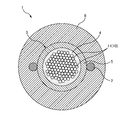
- FIG. 1A is a cross-sectional view of a loose tube type optical cable 1.
- FIG. 1B is a cross-sectional view of the loose tube 3.
- FIG. 2 is a cross-sectional view of another loose tube type optical cable 1.
- FIG. 3A is an explanatory diagram of an example of the intermittently connected optical fiber tape 10.
- FIG. 3B is an explanatory diagram of another example of the intermittently connected optical fiber tape 10.
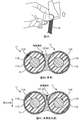
- FIG. 4A is an explanatory diagram of a state where the filler 4 attached to the optical fiber tape 10 is wiped off.
- 4B and 4C are cross-sectional views of the connecting portion 12 of the two adjacent optical fibers 11 of the intermittently connected optical fiber tape 10.
- FIG. 4B is an explanatory diagram of the destruction of the connecting portion 12 in the reference example.
- FIG. 4C is an explanatory diagram of the destruction of the connecting portion 12 in the present embodiment.
- FIG. 5 is an explanatory diagram of a manufacturing apparatus 30 for manufacturing the intermittently connected optical fiber tape 10 of the present embodiment.
- 6A and 6B are explanatory diagrams of the tape forming apparatus 50.
- FIG. FIG. 7 is an explanatory diagram of the degree of curing of the surface of the colored layer 11C.
- FIG. 8A is a cross-sectional view of the connecting portion 12 of two adjacent optical fibers 11 of the intermittently connected optical fiber tape 10 of the second embodiment.
- FIG. 8B is a cross-sectional view of the connecting portion 12 of two adjacent optical fibers 11 of the intermittently connected optical fiber tape 10 of the third embodiment.
- FIG. 8C is a cross-sectional view of the connecting portion 12 of two adjacent optical fibers 11 of the intermittently connected optical fiber tape 10 of the fourth embodiment.
- a manufacturing method comprising: In the colored layer forming step, A colorant is applied to the optical fiber; Curing the colorant so that uncured resin remains on the surface, forming the colored layer, In the tape forming step, Apply the connecting material to the surface of the colored layer where the uncured resin remains,
- the manufacturing method of the optical fiber tape is characterized by curing the coupling material and curing the uncured resin on the surface of the colored layer. According to such a method for manufacturing an optical fiber tape, it is possible to suppress the breakage of the connecting portion.
- the coloring material composed of a radical polymerization type ultraviolet curable resin is applied to the optical fiber, and the coloring material is irradiated with ultraviolet rays while an uncured resin remains on the surface due to oxygen inhibition.
- the colored layer is formed, and in the tape forming step, the coupling material composed of a radical polymerization type ultraviolet curable resin is applied to the surface of the colored layer where uncured resin remains, and the coupling material It is desirable that the connecting material is cured by irradiating the substrate with ultraviolet rays, and the uncured resin on the surface of the colored layer is cured. Thereby, when the colored layer is formed, the inside can be cured while leaving an uncured resin on the surface, so that the production of the optical fiber is facilitated.
- the coupling material is applied to the entire circumference of the optical fiber by applying the coupling material to the entire circumference of the optical fiber on which the colored layer is formed, and irradiating the coupling material with ultraviolet rays. It is desirable to cure the uncured resin on the surface of the colored layer. Thereby, it can suppress that uncured resin remains in the optical fiber tape after manufacture.
- the coupling material is applied between the entire circumference of the optical fiber on which the colored layer is formed and the optical fiber, while leaving a part of the coupling material applied between the optical fibers.
- the connecting portion is intermittently formed by removing a part and irradiating the connecting material with ultraviolet rays to cure the connecting material. Thereby, it is possible to easily form the connecting portion intermittently while applying the connecting material to the entire circumference of the optical fiber.
- the coloring material is irradiated with ultraviolet rays while leaving an uncured resin on the surface due to oxygen inhibition in an atmosphere having an oxygen concentration of 0.10% or more and 1.0% or less. It is desirable to form a layer. Thereby, destruction of a connection part can be suppressed.
- the peak intensity of the band corresponding to the double bond of the photopolymerization reaction when the surface of the colored layer is measured by IR spectrum is A
- the peak intensity when the colorant is uncured is A0
- the colorant When the peak intensity when A is most cured is A1
- the degree of cure It is desirable that the colored layer is formed so that is 60% or more and 90% or less. Thereby, destruction of a connection part can be suppressed.
- the connecting material desirably has a Young's modulus in the range of 10 to 300 MPa and a breaking strength in the range of 10 to 30 MPa. Thereby, it is possible to prevent the optical fiber from being damaged when the optical fiber of the optical fiber tape is separated into a single core.
- the connecting portion has a thickness of 150 ⁇ m or more. Thereby, destruction of a connection part can be suppressed.
- An optical fiber tape comprising: a connecting portion that connects the two adjacent optical fibers; Forming the colored layer by curing the coloring material so that uncured resin remains on the surface, Apply a connecting material to the surface of the colored layer where the uncured resin remains,
- the optical fiber tape is characterized in that the connecting material is cured to form the connecting portion, and the uncured resin on the surface of the colored layer is cured. According to such an optical fiber tape, breakage of the connecting portion can be suppressed.
- An optical fiber tape having a plurality of optical fibers having a colored layer and arranged in parallel; and a connecting portion for connecting the two adjacent optical fibers;
- An optical cable comprising a filler filled in the tube, Forming the colored layer by curing the coloring material so that uncured resin remains on the surface, Apply a connecting material to the surface of the colored layer where the uncured resin remains,
- the optical cable is characterized in that the connecting material is cured to form the connecting portion, and the uncured resin on the surface of the colored layer is cured.
- FIG. 1A is a cross-sectional view of a loose tube type optical cable 1.
- the loose tube type optical cable 1 includes a tension member 2 (strength member), a plurality of loose tubes 3, and a jacket 8.
- a plurality of loose tubes 3 are assembled around the tension member 2.
- the plurality of loose tubes 3 are assembled by being twisted (wound) around the tension member 2 in a spiral shape in one direction or in an SZ shape in which the spiral direction is periodically reversed.
- the outer periphery of the plurality of loose tubes 3 gathered around the tension member 2 is covered with the presser winding tape 7, and a sheath material is extruded on the outer periphery of the presser winding tape 7 to form the outer cover 8, whereby FIG.
- FIG. 1B is a cross-sectional view of the loose tube 3.
- the single structure of the loose tube 3 may be referred to as “optical cable” or “loose tube cable”.
- the loose tube 3 includes a plurality of optical fibers 11, a filler 4, and a tube 5.
- the filler 4 is a water stop material for filling the gap inside the tube 5 to stop the tube 5 and is, for example, jelly.
- the tube 5 is a tubular member that accommodates the plurality of optical fibers 11 and the filler 4.
- the plurality of optical fibers 11 includes one or a plurality of intermittently connected optical fiber tapes 10.
- FIG. 2 is a cross-sectional view of another loose tube type optical cable 1.
- the loose tube type optical cable 1 has two tension members 2 (strength members), a loose tube 3 and a jacket 8.
- the optical cable 1 shown in FIG. 2 may be called a center tube type cable or the like.
- the loose tube 3 is disposed inside the outer jacket 8 so as to be sandwiched between the two tension members 2.
- the loose tube 3 includes a plurality of optical fibers 11, a filler 4, and a tube 5.
- the plurality of optical fibers 11 includes one or a plurality of intermittently connected optical fiber tapes 10.
- a loose tube type optical cable 1 shown in FIG. 2 is formed by extruding a sheath material around the tension member 2 and the loose tube 3 while the tension member 2 is vertically attached to the loose tube 3. Is manufactured.
- FIG. 3A is an explanatory diagram of an example of the intermittently connected optical fiber tape 10.
- a direction parallel to the optical fiber 11 is referred to as a “longitudinal direction”.
- the direction in which the plurality of optical fibers 11 constituting the intermittently connected optical fiber tape 10 are arranged is referred to as a “tape width direction”.
- the intermittently connected optical fiber tape 10 is an optical fiber tape in which a plurality of optical fibers 11 are connected in parallel. Two adjacent optical fibers 11 are connected by a connecting portion 12. A plurality of connecting portions 12 that connect two adjacent optical fibers 11 are intermittently arranged in the longitudinal direction.
- connection part 12 of the intermittent connection type optical fiber tape 10 is intermittently arrange
- the connecting portion 12 is formed by applying an ultraviolet curable resin serving as an adhesive (connecting material 14) and then curing it by irradiating with ultraviolet rays (described later).
- a region other than the connecting portion 12 between the two adjacent optical fibers 11 is a non-connecting portion 13 (separating portion). In the unconnected portion 13, the adjacent two optical fibers 11 are not restrained.
- the intermittently connected optical fiber tape 10 can be rounded into a cylindrical shape (bundle shape) or folded, and a large number of optical fibers 11 can be accommodated at high density.
- a normal optical fiber tape 10 in which a plurality of optical fibers 11 arranged in the tape width direction are collectively covered may be used instead of the intermittently connected optical fiber tape 10.
- FIG. 3B is an explanatory diagram of another example of the intermittently connected optical fiber tape 10.
- the number of cores of the intermittently connected optical fiber tape 10 can be changed as appropriate.
- positioned intermittently can change arrangement
- FIG. 4A is an explanatory diagram showing a state where the filler 4 adhering to the optical fiber tape 10 is wiped off.
- the operator removes the intermittently fixed optical fiber tape 10 from the loose tube 3 of the optical cable 1 and then cleans the filler 4 (for example, jelly) attached to the intermittently fixed optical fiber tape 10. Wipe off with a sheet (for example, wipe paper).
- the connecting portion 12 of the intermittently fixed optical fiber tape 10 may be broken by applying a force that twists the optical fiber tape 10 with an operator's finger.
- the intermittently fixed type optical fiber tape 10 is separated into single optical fibers 11 (a plurality of optical fibers 11 constituting the optical fiber tape 10 are separated from each other).
- the connecting portion 12 of the intermittently fixed optical fiber tape 10 is not broken when the filler 4 attached to the optical fiber tape 10 is wiped off.
- FIG. 4B and 4C are cross-sectional views of the connecting portion 12 of the two adjacent optical fibers 11 of the intermittently connected optical fiber tape 10.
- FIG. 4B is an explanatory diagram of the destruction of the connecting portion 12 in the reference example.
- FIG. 4C is explanatory drawing of destruction of the connection part 12 in this embodiment.
- the optical fiber 11 includes an optical fiber portion 11A, a coating layer 11B, and a colored layer 11C.
- the optical fiber 11 may be called an optical fiber strand or an optical fiber core wire.
- the diameter of the optical fiber 11 is about 250 ⁇ m.
- the optical fiber portion 11A is composed of a core and a clad.
- the optical fiber portion 11A is, for example, a quartz glass fiber.
- the diameter (cladding diameter) of the optical fiber portion 11A is, for example, about 125 ⁇ m.
- the coating layer 11B is a layer that covers the optical fiber portion 11A.
- the coating layer 11B is composed of, for example, a primary coating layer (primary coating) and a secondary coating layer (secondary coating).
- the diameter of the coating layer 11B is about 240 ⁇ m, for example.
- the colored layer 11C is a layer formed on the surface of the coating layer 11B.
- the colored layer 11C is formed by applying a coloring material to the surface of the coating layer 11B.
- the colorant is usually colored, but may be colorless.
- the colorant is made of an ultraviolet curable resin.
- the connecting portion 12 is formed by applying and curing the connecting material 14 (ultraviolet curable resin) on the surface of the colored layer 11C.
- the resin constituting the connecting portion 12 is broken on the colored layer 11C.
- the reason why the connecting portion 12 is broken at such a location is not clear, but peeling occurs at the interface between the colored layer 11C and the connecting portion 12 (see the thick line portion at the interface in the figure). It is considered that the thin resin layer of the portion 12 was broken and the connecting portion 12 was broken.
- the structure is such that peeling at the interface between the colored layer 11C and the connecting portion 12 does not easily occur.
- the breakage of the connecting portion 12 in the thin resin layer is suppressed, and as shown in FIG. 4C, the breaking of the connecting portion 12 proceeds while the colored layer 11C and the connecting portion 12 are in close contact with each other.
- the connecting portion 12 is less likely to be broken, and the optical fiber 11 can be prevented from being unintentionally separated.
- the connecting portion 12 when the connecting portion 12 is split to separate the optical fiber 11 of the intermittently connected optical fiber tape 10, the colored layer 11 ⁇ / b> C and the connecting portion 12 are in close contact as shown in FIG. 4C. As a result, the connecting portion 12 is broken, whereby the optical fiber 11 is separated from the single core.
- the intermittently connected optical fiber tape 10 is manufactured by adjusting the adhesion between the colored layer 11C and the connecting portion 12 while selecting the connecting material 14 having an appropriate Young's modulus and breaking strength. It is desirable.
- FIG. 5 is an explanatory diagram of a manufacturing apparatus 30 that manufactures the intermittently connected optical fiber tape 10 of the present embodiment.
- the manufacturing apparatus 30 includes a plurality (here, four) of fiber supply sources 31, a coloring apparatus 40, and a tape forming apparatus 50.
- the fiber supply source 31 is a supply device (supply source) that supplies the optical fiber 11 to the coloring device 40.
- the optical fiber 11 supplied by the fiber supply source 31 is the optical fiber 11 (an optical fiber composed of the optical fiber portion 11A and the coating layer 11B) before forming the colored layer 11C.
- the coloring device 40 is a device that forms the colored layer 11C on the outer periphery of the coating layer 11B.
- the coloring device 40 forms the colored layer 11 ⁇ / b> C on the entire circumference of the coating layer 11 ⁇ / b> B over the longitudinal direction of the optical fiber 11.
- the coloring device 40 includes a coloring material application unit 41 and a curing light source 42.
- the coloring material application unit 41 is an application device that applies a coloring material made of an ultraviolet curable resin to the outer periphery of the coating layer 11B.
- the coloring material application unit 41 applies the coloring material to the entire circumference of the coating layer 11 ⁇ / b> B along the longitudinal direction of the optical fiber 11 by inserting the optical fiber 11 through a coating die filled with a liquid coloring material, for example.
- the curing light source 42 is a light source that irradiates the coloring material made of the ultraviolet curable resin with ultraviolet rays.
- the coloring material applied to the outer periphery of the coating layer 11B is cured by being irradiated with the ultraviolet rays of the curing light source 42.
- the colored layer 11C is formed by the cured coloring material.
- the coloring device 40 supplies the optical fiber 11 on which the colored layer 11 ⁇ / b> C is formed to the tape forming device 50.
- the tape forming apparatus 50 is an apparatus that forms the intermittently connected optical fiber tape 10 by intermittently forming the connecting portions 12.
- 6A and 6B are explanatory diagrams of the tape forming apparatus 50.
- FIG. The tape forming apparatus 50 includes a connecting material applying unit 51, a removing unit 52, and a light source 53.
- the connecting material application unit 51 is an apparatus that applies the connecting material 14 made of an ultraviolet curable resin between adjacent optical fibers 11.
- the connecting material application unit 51 inserts a plurality (here, four) of optical fibers 11 through a coating die filled with the liquid connecting material 14, thereby extending the entire circumference of the optical fiber 11 over the longitudinal direction of the optical fiber 11.
- a liquid connecting material 14 is applied between (the entire circumference of the colored layer 11 ⁇ / b> C) and the optical fiber 11.
- the removal unit 52 is a device that removes a part of the liquid connecting material 14 applied between the optical fibers 11 while leaving a part thereof.
- the removing unit 52 includes a rotary blade 521 having a concave portion 521A (see FIG. 6A).
- the rotary blade 521 is rotated in accordance with the supply speed of the optical fiber 11, and the connecting member 14 is moved in the concave portion 521A of the rotary blade 521. While remaining, the connecting material 14 applied between the optical fibers 11 is removed (cut) at the outer edge of the rotary blade 521.
- the removal unit 52 removes a part of the liquid coupling material 14 applied between the optical fibers 11 by damming the coupling material 14 with the outer edge of the rotary blade 521.
- the light source 53 is a light source that irradiates the connecting material 14 made of an ultraviolet curable resin with ultraviolet rays.
- the light source 53 includes a temporary curing light source 53A and a main curing light source 53B.
- the temporary curing light source 53A irradiates ultraviolet rays to temporarily cure the connecting material 14.
- the temporarily cured connecting material 14 is not completely cured, but is cured on the surface.
- the main curing light source 53B irradiates the ultraviolet rays stronger than the temporary curing light source 53A to fully cure the connecting material 14.
- the fully cured ultraviolet curable resin is cured to the inside (however, since the intermittently connected optical fiber tape 10 can be rounded into a cylindrical shape or folded, the fully cured connecting portion 12 is Have moderate elasticity).
- the optical fibers 11 immediately after coming out of the connecting material applying part 51 and the removing part 52 are spaced from each other.
- the temporary curing light source 53 ⁇ / b> A irradiates the connecting material 14 with ultraviolet rays to temporarily cure the connecting material 14.
- the tape forming apparatus 50 gradually narrows the interval between the optical fibers 11 after the connection material 14 is temporarily cured, and arranges the plurality of optical fibers 11 in parallel to collect the tapes.
- the connection material 14 is pre-cured, even if the parts (separation part) from which the connection material 14 was removed contact, it does not need to connect.
- the main curing light source 53B irradiates ultraviolet rays and the coupling material 14 is finally cured, the intermittently coupled optical fiber tape 10 shown in FIG. 3A is manufactured.
- the colored layer 11C and the connecting portion 12 are formed as follows.
- a radical polymerization type ultraviolet curable resin is used as a coloring material for forming the colored layer 11C, and the oxygen concentration at the time of forming the colored layer 11C is adjusted by adjusting the oxygen concentration of the coloring device 40.
- the degree of cure of the surface of the colored layer 11C is adjusted so that uncured resin remains on the surface.
- oxygen inhibition occurs on the surface of the coloring material, which is a radical polymerization type ultraviolet curable resin, so that the uncured resin on the surface of the colored layer 11C increases and the surface of the colored layer 11C increases.
- the degree of cure is low. However, although the uncured resin remains on the surface of the colored layer 11C, the inside of the colored layer 11C is cured, so that the optical fiber 11 can be easily manufactured compared to the uncured state of the colored layer 11C. .
- FIG. 7 is an explanatory diagram of the degree of curing of the surface of the colored layer 11C.
- the graph in the figure is a graph of the IR spectrum measurement result.
- the horizontal axis of the graph indicates the wave number (cm ⁇ 1 ), and the vertical axis indicates the absorbance.
- the peak intensity of the band corresponding to the double bond in the photopolymerization reaction of the colorant (ultraviolet curable resin) is measured.
- the band corresponding to the CH out-of-plane vibration of vinyl group is around 808 cm ⁇ 1 .
- the measured value of the peak intensity of the colored layer 11C in an uncured state of the colorant is A0, and the peak intensity of the colored layer 11C in the most cured state in an oxygen-free state (the oxygen concentration is less than 0.001% of the measurement limit).
- the measured value of A1 is A1
- the degree of cure of the surface of the colored layer 11C is calculated as follows.
- Curing degree (%) ⁇ (A0-A) / (A0-A1) ⁇ ⁇ 100
- the degree of cure of the surface of the uncured colored layer 11C is 0%, and the degree of cure of the surface of the colored layer 11C when the colorant is cured in the oxygen-free state (most cured state) is 100%. Become.
- the oxygen concentration can be measured using an oxygen concentration meter attached to the coloring device 40.
- the colored layer 11C (before the formation of the connecting portion 12) is formed so that the degree of cure of the surface of the colored layer 11C is 60% or more and 90% or less.
- the degree of cure of the surface of the colored layer 11C is greater than 90%, peeling tends to occur at the interface between the colored layer 11C and the connecting portion 12 (see the thick line portion at the interface in FIG. 4B).
- the connecting portion 12 may be destroyed unintentionally. If the degree of cure of the surface of the colored layer 11C is less than 60%, the adhesion between the colored layer 11C and the connecting portion 12 is too high, and the optical fiber 11 of the intermittently connected optical fiber tape 10 is single-core.
- the covering layer 11B When separating, there is a possibility that the covering layer 11B may be broken together with the connecting portion 12.
- the degree of cure of the surface of the colored layer 11C is in the range of 60% or more and 90% or less, as will be described later, the optical fiber is suppressed while preventing the connection part 12 from being unintentionally destroyed. It is possible to prevent the coating layer 11B from being destroyed when the cores 11 are separated from each other.
- the oxygen concentration at the time of forming the colored layer 11C is adjusted to 0.10% or more and 1.0% or less in order to set the degree of curing of the surface of the colored layer 11C to 60% or more and 90% or less. ing.
- the degree of cure of the surface of the colored layer 11C becomes larger than 90% because the oxygen concentration is low.
- the optical fiber tape 10 When the filler 4 adhering to the surface is wiped off (see FIG. 4A), the connecting portion 12 may be unintentionally destroyed.
- the oxygen concentration at the time of formation of the colored layer 11C is larger than 1.0%, the adhesion between the colored layer 11C and the connecting portion 12 is too high, and the optical fiber 11 of the intermittently connected optical fiber tape 10 is used.
- the coating layer 11B may be broken together with the connecting portion 12.
- the connecting portion 12 is formed in the tape forming apparatus 50.
- a radical polymerization type ultraviolet curable resin is also used for the connecting member 14 forming the connecting portion 12.
- the tape forming apparatus 50 applies the liquid connecting material 14 between the entire circumference of the colored layer 11 ⁇ / b> C and the optical fiber 11 in the connecting material applying unit 51, and between the optical fibers 11 in the removing unit 52. A part of the applied liquid connecting material 14 is removed, and the light source 53 irradiates the connecting material 14 with ultraviolet rays.
- the coupling material 14 that is a radical polymerization type ultraviolet curable resin is applied to the surface of the colored layer 11C where the uncured resin remains, and the coupling material 14 is irradiated with ultraviolet rays.
- the photopolymerization initiator of the connecting material 14 is irradiated with ultraviolet rays, radicals are formed, the connecting material 14 is cured to form the connecting portion 12, and the uncured resin on the surface of the colored layer 11C is also cured.
- the connection part 12 is formed on the colored layer 11C having a curing degree of 100%, the adhesion between the colored layer 11C and the connection part 12 is increased, and the connection between the colored layer 11C and the connection part 12 is increased. Separation at the interface can be suppressed.
- the liquid connecting material 14 when the connecting material 14 is applied, the liquid connecting material 14 is applied to the entire circumference of the colored layer 11 ⁇ / b> C, and thus the layer of the connecting material 14 is formed over the entire circumference of the optical fiber 11. (See FIG. 4C). For this reason, since the colored layer 11C is not exposed in the completed intermittently connected optical fiber tape 10, uncured resin does not have to be exposed. Note that when the colored layer 11C is formed, uncured resin remains on the surface of the colored layer 11C. However, when the liquid connecting material 14 is applied to the entire circumference of the colored layer 11C, the connecting portion 12 is formed. In doing so, the uncured resin on the surface of the colored layer 11C is cured. Therefore, even if the completed intermittently connected optical fiber tape 10 is analyzed, it is necessary to specify the characteristics and characteristics that uncured resin remains on the surface of the colored layer 11C when the colored layer 11C is formed. There are impossible and impractical circumstances.
- Example 1 The 12-fiber intermittently connected optical fiber tape 10 was manufactured by the manufacturing method described above.
- a urethane acrylate ultraviolet curable resin (resin A: Young's modulus 800 MPa, breaking strength 50 MPa) was used. Curing the surface of the colored layer 11C by adjusting the oxygen concentration during the formation of the colored layer 11C stepwise in the range from the oxygen-free state (the oxygen concentration is less than 0.001% of the measurement limit) to 1.0%. The degree was adjusted stepwise from 100% to 60%. The degree of cure of the surface of the colored layer 11C was measured by measuring the peak intensity near 808 cm ⁇ 1 in FT-IR.
- mold optical fiber tape 10 was done, and the presence or absence of the destruction of the connection part 12 after wiping off a jelly was evaluated.
- separates the optical fiber 11 by splitting the connection part 12 of the intermittent connection type optical fiber tape 10 is performed, and the coating layer 11B of the optical fiber 11 after the single core separation (after the connection part 12 is split) The presence or absence of destruction was also evaluated.
- Example 1 The experimental results of Example 1 are as shown in Table 1 below.
- Example 1 in any sample (material numbers A1 to A7), the coating layer 11B of the optical fiber 11 after the single-core separation was broken. This is considered to be because the Young's modulus and breaking strength of the connecting portion 12 formed of the resin A are high (however, even when the connecting portion 12 is formed of the resin A, the connection after wiping is performed as described above. The effect that the destruction of the portion 12 can be suppressed is obtained).
- Example 2 The 12-fiber intermittently connected optical fiber tape 10 was manufactured in the same manner as in Example 1 by changing the resin (connecting material 14) forming the connecting portion 12.
- the Young's modulus and breaking strength of Resins B to F are as shown in Table 2.
- the presence or absence of the destruction of the connection part 12 after wiping off a jelly and the presence or absence of the destruction of the coating layer 11B of the optical fiber 11 after single fiber separation were evaluated. If there is no breakage of the connecting portion 12 after wiping off the jelly and there is no breakage of the coating layer 11B of the optical fiber 11 after the single fiber separation, the determination is “good”, and at least one of the breakage is found. In the case of a failure, the determination was “impossible”.
- the experimental results of Example 2 are as shown in Table 2 below.
- the degree of cure of the surface of the colored layer 11C is 60% or more and 90% or less (the oxygen concentration when forming the colored layer 11C is 0.10% or more and 1.0%). %), When the colored layer 11C is formed, the breakage of the connecting portion 12 at the time of wiping off the jelly can be suppressed. Further, the colored layer 11C is formed with the degree of cure of the surface of the colored layer 11C in the range of 60% or more and 90% or less, and the connecting portion 12 is made of the resin B to the resin E having a Young's modulus of 10 to 300 MPa and a breaking strength of 10 to 30 MPa.
- the resin forming the connecting portion 12 has a Young's modulus of 10 to 300 MPa and a breaking strength of 10 to 30 MPa.
- Example 3 The 12-fiber intermittently connected optical fiber tape 10 was manufactured in the same manner as in Examples 1 and 2 by changing the thickness of the connecting portion 12 (the dimension in the thickness direction in FIG. 4C) stepwise.
- the colored layer 11C is formed with the degree of cure of the surface of the colored layer 11C in the range of 60% or more and 90% or less, and the connecting portion 12 is made of the resin B to the resin E having a Young's modulus of 10 to 300 MPa and a breaking strength of 10 to 30 MPa. Formed.
- the presence or absence of breakage of the connecting portion 12 after wiping off the jelly and the presence or absence of breakage of the coating layer 11B of the optical fiber 11 after single-fiber separation were evaluated.
- the experimental results of Example 3 are as shown in Table 3 below.
- the connecting part 12 When the thickness of the connecting part 12 was 120 ⁇ m or less, the connecting part 12 after wiping off the jelly was broken. On the other hand, when the thickness of the connecting portion 12 is 150 ⁇ m or more, the breaking of the connecting portion 12 after wiping off the jelly can be suppressed. In addition, even if the thickness of the connection part 12 was 150 micrometers or more, the coating layer 11B of the optical fiber 11 after single fiber separation was not destroyed. For this reason, the thickness of the connecting portion 12 is desirably 150 ⁇ m or more.
- FIG. 8A is a cross-sectional view of the connecting portion 12 of two adjacent optical fibers 11 of the intermittently connected optical fiber tape 10 of the second embodiment.
- the connecting portion 12 may be configured such that the thickness (dimension in the thickness direction) of the connecting portion 12 is constant.
- the liquid connecting material 14 when the connecting material 14 is applied, the liquid connecting material 14 is applied to the entire circumference of the colored layer 11 ⁇ / b> C, so that the layer of the connecting material 14 extends over the entire circumference of the optical fiber 11. Is formed. For this reason, in the second embodiment, since the colored layer 11C is not exposed, the uncured resin does not need to be exposed.
- FIG. 8B is a cross-sectional view of the connecting portion 12 of two adjacent optical fibers 11 of the intermittently connected optical fiber tape 10 of the third embodiment.
- the connecting portion 12 may be formed only between the optical fibers 11.
- FIG. 8C is a cross-sectional view of the connecting portion 12 of two adjacent optical fibers 11 of the intermittently connected optical fiber tape 10 of the fourth embodiment.
- the connecting portion 12 may be formed so as to be biased to one side (upper side in the drawing) in the thickness direction, without being uniformly formed in the thickness direction.
- the connecting material 14 is applied only to a part of the peripheral surface of the optical fiber 11. For this reason, in the third embodiment and the fourth embodiment, the colored layer 11C is exposed even after the intermittently connected optical fiber tape 10 is completed. Since the connecting material 14 is not applied to the exposed portion of the colored layer 11C, an uncured resin remains on the surface of the colored layer 11C at this portion even after the intermittently connected optical fiber tape 10 is completed. . However, if it is the structure of the connection part 12 of 3rd Embodiment or 4th Embodiment, since it is not necessary to apply
- a radical polymerization type ultraviolet curing is used as a coloring material for forming the colored layer 11C.
- the oxygen concentration during the formation of the colored layer 11C is adjusted by adjusting the oxygen concentration of the coloring device 40 using a resin, so that the uncured resin remains on the surface of the colored layer 11C. Adjust the degree of cure.
- a connecting material 14 that is a radical polymerization type ultraviolet curable resin is applied to the surface of the colored layer 11C where the uncured resin remains, and the connecting material 14 is irradiated with ultraviolet rays to form the connecting portion 12.
- the intermittently connected optical fiber tape 10 is manufactured. Thereby, the adhesiveness of 11 C of colored layers and the connection part 12 can be improved, and destruction of the connection part 12 at the time of wiping off a jelly can be suppressed.
- the degree of cure of the surface of the colored layer 11C so that uncured resin remains on the surface of the colored layer 11C by adjusting the oxygen concentration at the time of forming the colored layer 11C. is adjusted.
- the degree of curing of the surface of the colored layer 11C is adjusted by adjusting the intensity of the ultraviolet rays applied to the coloring material so that an uncured resin remains on the surface of the colored layer 11C. You may do it.
- the intensity of the ultraviolet rays applied to the coloring material is weakened, the inside of the colored layer 11C becomes uncured and soft, so that it becomes difficult to manufacture the optical fiber 11 (colored fiber).
- the method of adjusting the oxygen concentration at the time of forming the colored layer 11C only leaves uncured resin on the surface of the colored layer 11C, so that the optical fiber 11 (colored fiber) can be easily manufactured.
- the colored layer 11C is colored so that the degree of cure of the colored layer 11C is 60% or more and 90% or less. It is desirable to form the layer 11C.
- 1 loose tube type optical cable 1 tension member, 3 Loose tube, 4 filling material (water-stopping material, jelly), 5 Tube, 7 Presser tape, 8 Jacket, 10 Intermittently fixed optical fiber tape, 11 optical fiber, 11A optical fiber part, 11B coating layer, 11C coloring layer, 12 connecting parts, 13 non-connecting parts, 14 connecting materials, 30 manufacturing equipment, 31 fiber source, 40 coloring device, 41 coloring material application part, 42 light source for curing, 50 tape making device, 51 connecting material application part, 52 removal part, 521 rotary blade, 521A recess, 53 light source, 53A light source for temporary curing, 53B light source for main curing
Landscapes
- Physics & Mathematics (AREA)
- Engineering & Computer Science (AREA)
- Life Sciences & Earth Sciences (AREA)
- Chemical & Material Sciences (AREA)
- Manufacturing & Machinery (AREA)
- General Physics & Mathematics (AREA)
- Optics & Photonics (AREA)
- General Chemical & Material Sciences (AREA)
- Geochemistry & Mineralogy (AREA)
- Materials Engineering (AREA)
- Organic Chemistry (AREA)
- Chemical Kinetics & Catalysis (AREA)
- General Life Sciences & Earth Sciences (AREA)
- Optical Fibers, Optical Fiber Cores, And Optical Fiber Bundles (AREA)
Abstract
Description
複数の光ファイバのそれぞれに着色層を形成する着色層形成工程と、
着色層の表面に塗布した連結材を硬化させて連結部を形成することによって、隣接する光ファイバの間を前記連結部で連結した光ファイバテープを形成するテープ化工程と
を有する光ファイバテープの製造方法であって、
前記着色層形成工程において、
着色材を前記光ファイバに塗布し、
表面に未硬化の樹脂が残存するように前記着色材を硬化させて、前記着色層を形成し、
前記テープ化工程において、
未硬化の樹脂が残存した前記着色層の表面に前記連結材を塗布し、
前記連結材を硬化させるとともに、前記着色層の表面の未硬化の樹脂を硬化させる
ことを特徴とする光ファイバテープの製造方法である。 The main invention for achieving the above object is:
A colored layer forming step of forming a colored layer on each of the plurality of optical fibers;
An optical fiber tape having a tape forming step of forming an optical fiber tape in which adjacent optical fibers are connected by the connecting portion by curing the connecting material applied to the surface of the colored layer to form a connecting portion. A manufacturing method comprising:
In the colored layer forming step,
A colorant is applied to the optical fiber;
Curing the colorant so that uncured resin remains on the surface, forming the colored layer,
In the tape forming step,
Apply the connecting material to the surface of the colored layer where the uncured resin remains,
In the optical fiber tape manufacturing method, the connecting material is cured and an uncured resin on the surface of the colored layer is cured.
着色層の表面に塗布した連結材を硬化させて連結部を形成することによって、隣接する光ファイバの間を前記連結部で連結した光ファイバテープを形成するテープ化工程と
を有する光ファイバテープの製造方法であって、
前記着色層形成工程において、
着色材を前記光ファイバに塗布し、
表面に未硬化の樹脂が残存するように前記着色材を硬化させて、前記着色層を形成し、
前記テープ化工程において、
未硬化の樹脂が残存した前記着色層の表面に前記連結材を塗布し、
前記連結材を硬化させるとともに、前記着色層の表面の未硬化の樹脂を硬化させることを特徴とする光ファイバテープの製造方法が明らかとなる。このような光ファイバテープの製造方法によれば、連結部の破壊を抑制することができる。 A colored layer forming step of forming a colored layer on each of the plurality of optical fibers;
An optical fiber tape having a tape forming step of forming an optical fiber tape in which adjacent optical fibers are connected by the connecting portion by curing the connecting material applied to the surface of the colored layer to form a connecting portion. A manufacturing method comprising:
In the colored layer forming step,
A colorant is applied to the optical fiber;
Curing the colorant so that uncured resin remains on the surface, forming the colored layer,
In the tape forming step,
Apply the connecting material to the surface of the colored layer where the uncured resin remains,
The manufacturing method of the optical fiber tape is characterized by curing the coupling material and curing the uncured resin on the surface of the colored layer. According to such a method for manufacturing an optical fiber tape, it is possible to suppress the breakage of the connecting portion.
隣接する2心の前記光ファイバを連結する連結部と
を備えた光ファイバテープであって、
表面に未硬化の樹脂が残存するように着色材を硬化させて前記着色層を形成し、
未硬化の樹脂が残存した前記着色層の表面に連結材を塗布し、
前記連結材を硬化させて前記連結部を形成するとともに、前記着色層の表面の未硬化の樹脂を硬化させたことを特徴とする光ファイバテープが明らかとなる。このような光ファイバテープによれば、連結部の破壊を抑制することができる。 A plurality of optical fibers having a colored layer and arranged in parallel;
An optical fiber tape comprising: a connecting portion that connects the two adjacent optical fibers;
Forming the colored layer by curing the coloring material so that uncured resin remains on the surface,
Apply a connecting material to the surface of the colored layer where the uncured resin remains,
The optical fiber tape is characterized in that the connecting material is cured to form the connecting portion, and the uncured resin on the surface of the colored layer is cured. According to such an optical fiber tape, breakage of the connecting portion can be suppressed.
前記光ファイバテープを収容するチューブと、
前記チューブに充填された充填材と
を備えた光ケーブルであって、
表面に未硬化の樹脂が残存するように着色材を硬化させて前記着色層を形成し、
未硬化の樹脂が残存した前記着色層の表面に連結材を塗布し、
前記連結材を硬化させて前記連結部を形成するとともに、前記着色層の表面の未硬化の樹脂を硬化させたことを特徴とする光ケーブルが明らかとなる。このような光ケーブルであれば、光ファイバテープに付着した充填材を拭き取る際に、連結部の破壊を抑制することができる。 An optical fiber tape having a plurality of optical fibers having a colored layer and arranged in parallel; and a connecting portion for connecting the two adjacent optical fibers;
A tube containing the optical fiber tape;
An optical cable comprising a filler filled in the tube,
Forming the colored layer by curing the coloring material so that uncured resin remains on the surface,
Apply a connecting material to the surface of the colored layer where the uncured resin remains,
The optical cable is characterized in that the connecting material is cured to form the connecting portion, and the uncured resin on the surface of the colored layer is cured. With such an optical cable, when the filler adhering to the optical fiber tape is wiped off, the breakage of the connecting portion can be suppressed.
<光ケーブル1の構成>
図1Aは、ルースチューブ型の光ケーブル1の断面図である。このルースチューブ型の光ケーブル1は、テンションメンバ2(抗張力体)と、複数のルースチューブ3と、外被8とを有する。テンションメンバ2の周囲に複数のルースチューブ3が集合されている。複数のルースチューブ3は、一方向に螺旋状に、若しくは周期的に螺旋方向を反転させたSZ状に、テンションメンバ2の周囲で撚り合わせて(巻き付けて)集合されている。テンションメンバ2の周囲に集合された複数のルースチューブ3の外周を押え巻きテープ7で覆い、押え巻きテープ7の外周にシース材を押出成形して外被8が形成されることによって、図1Aに示すルースチューブ型の光ケーブル1が製造される。 === First Embodiment ===
<Configuration of
FIG. 1A is a cross-sectional view of a loose tube type
間欠連結型光ファイバテープ10は、複数の光ファイバ11を並列させて間欠的に連結した光ファイバテープである。隣接する2心の光ファイバ11は、連結部12によって連結されている。隣接する2心の光ファイバ11を連結する複数の連結部12は、長手方向に間欠的に配置されている。また、間欠連結型光ファイバテープ10の複数の連結部12は、長手方向及びテープ幅方向に2次元的に間欠的に配置されている。連結部12は、接着剤(連結材14)となる紫外線硬化樹脂を塗布した後に紫外線を照射して硬化させることによって、形成されている(後述)。なお、連結部12を熱可塑性樹脂で構成することも可能である。隣接する2心の光ファイバ11間の連結部12以外の領域は、非連結部13(分離部)になっている。非連結部13では、隣接する2心の光ファイバ11同士は拘束されていない。これにより、間欠連結型光ファイバテープ10を丸めて筒状(束状)にしたり、折り畳んだりすることが可能になり、多数の光ファイバ11を高密度に収容することが可能になる。但し、間欠連結型光ファイバテープ10の代わりに、テープ幅方向に並ぶ複数の光ファイバ11を一括被覆した通常の光ファイバテープ10を用いてもよい。 FIG. 3A is an explanatory diagram of an example of the intermittently connected
The intermittently connected
・間欠連結型光ファイバテープ10の製造方法の概要
図5は、本実施形態の間欠連結型光ファイバテープ10を製造する製造装置30の説明図である。製造装置30は、複数(ここでは4つ)のファイバ供給源31と、着色装置40と、テープ化装置50とを有する。 <Method for Manufacturing Intermittently Connected
Outline of Manufacturing Method of Intermittently Connected
本実施形態では、既に説明したように、着色層11Cと連結部12との密着性を向上させることによって、着色層11Cと連結部12との界面における剥離が生じにくい構造を実現させている(図4C参照)。本実施形態では、着色層11Cと連結部12との密着性を調整するために、次のように着色層11C及び連結部12を形成している。 -About formation of
・実施例1
前述の製造方法により、12心の間欠連結型光ファイバテープ10を製造した。連結材14には、ウレタンアクリレート系の紫外線硬化樹脂(樹脂A:ヤング率800MPa、破断強度50MPa)を用いた。着色層11Cの形成時の酸素濃度を無酸素状態(酸素濃度が測定限界の0.001%未満)から1.0%までの範囲で段階的に調整することによって、着色層11Cの表面の硬化度を100%から60%の範囲で段階的に調整した。なお、FT-IRにおいて808cm-1付近のピーク強度を測定することにより、着色層11Cの表面の硬化度を測定した。 <Example>
Example 1
The 12-fiber intermittently connected

連結部12を形成する樹脂(連結材14)を異ならせて、実施例1と同様に12心の間欠連結型光ファイバテープ10を製造した。なお、樹脂B~樹脂Fのヤング率及び破断強度は表2に示す通りである。また、実施例1と同様に、ジェリーの拭き取り後の連結部12の破壊の有無の評価と、単心分離後の光ファイバ11の被覆層11Bの破壊の有無の評価を行った。ジェリーの拭き取り後の連結部12の破壊の破壊が無く、且つ、単心分離後の光ファイバ11の被覆層11Bの破壊が無い場合には、判定を「良」とし、少なくとも一方の破壊があった場合には判定を「不可」とした。実施例2の実験結果は、次の表2に示す通りである。 Example 2
The 12-fiber intermittently connected
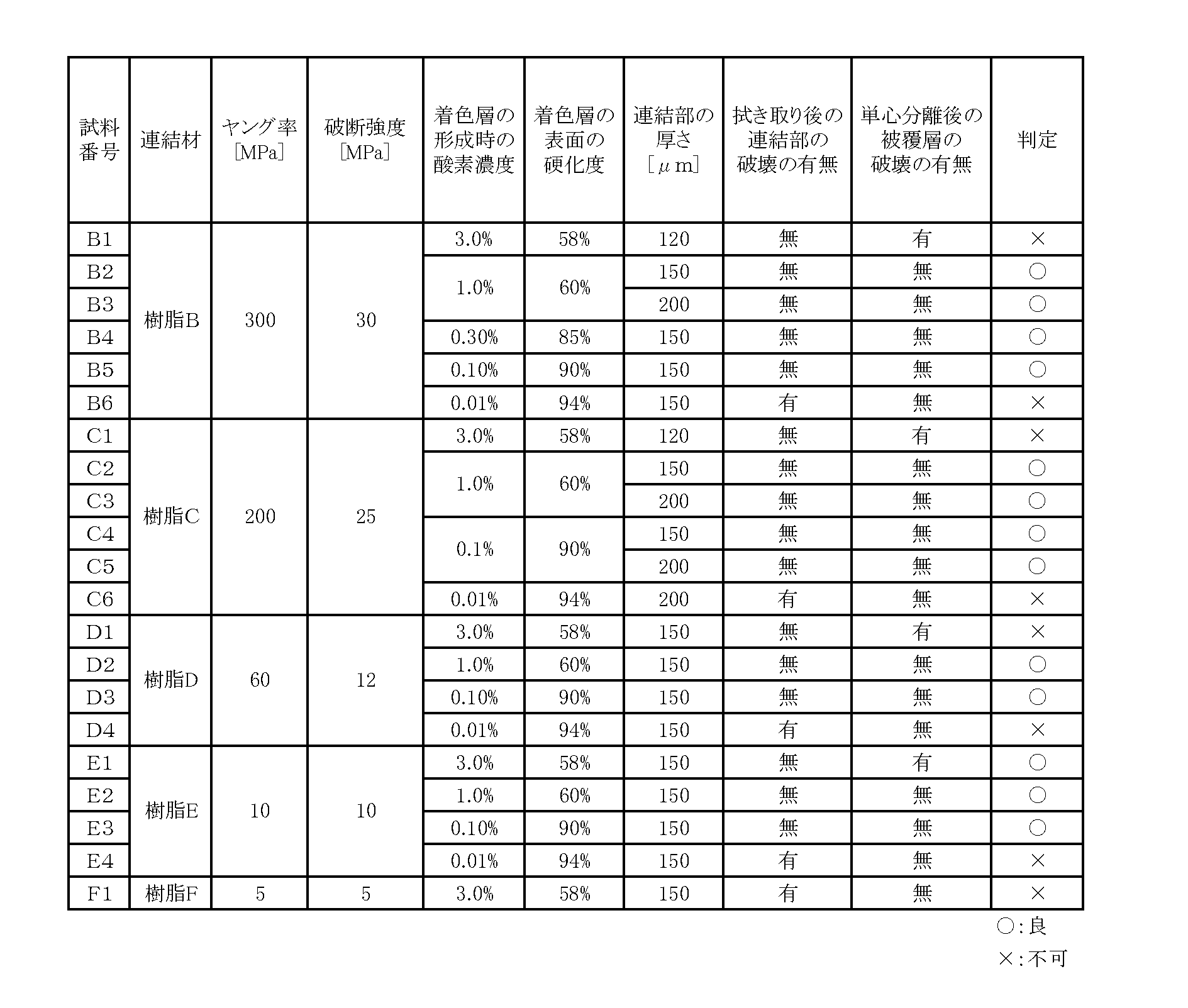
また、着色層11Cの表面の硬化度を60%以上90%以下の範囲にして着色層11Cを形成するとともに、ヤング率10~300MPa、破断強度10~30MPaの樹脂B~樹脂Eにより連結部12を形成すれば、ジェリーの拭き取り時の連結部12の破壊を抑制できるだけでなく、単心分離後の光ファイバ11の被覆層11Bの破壊を抑制することも両立できた(これに対し、前述の樹脂Aにより連結部12を形成した場合には、単心分離後の光ファイバ11の被覆層11Bが破壊されていた)。したがって、連結部12を形成する樹脂は、ヤング率が10~300MPa、破断強度が10~30MPaであることが望ましい。 Even when the connecting
Further, the
連結部12の厚さ(図4Cの厚さ方向の寸法)を段階的に異ならせて、実施例1、2と同様に12心の間欠連結型光ファイバテープ10を製造した。なお、着色層11Cの表面の硬化度を60%以上90%以下の範囲にして着色層11Cを形成するとともに、ヤング率10~300MPa、破断強度10~30MPaの樹脂B~樹脂Eにより連結部12を形成した。実施例1、2と同様に、ジェリーの拭き取り後の連結部12の破壊の有無の評価と、単心分離後の光ファイバ11の被覆層11Bの破壊の有無の評価を行った。実施例3の実験結果は、次の表3に示す通りである。 Example 3
The 12-fiber intermittently connected

図8Aは、第2実施形態の間欠連結型光ファイバテープ10の隣接する2心の光ファイバ11の連結部12における断面図である。第2実施形態に示すように、連結部12における厚さ(厚さ方向の寸法)が一定になるように、連結部12を構成しても良い。 === Another Embodiment ===
FIG. 8A is a cross-sectional view of the connecting
図8Cは、第4実施形態の間欠連結型光ファイバテープ10の隣接する2心の光ファイバ11の連結部12における断面図である。第4実施形態に示すように、連結部12が厚さ方向に均等に形成されずに、連結部12が厚さ方向の一方(図中の上側)に偏って形成されても良い。 FIG. 8B is a cross-sectional view of the connecting
FIG. 8C is a cross-sectional view of the connecting
上記の実施形態は、本発明の理解を容易にするためのものであり、本発明を限定して解釈するためのものではない。本発明は、その趣旨を逸脱することなく、変更・改良され得ると共に、本発明には、その等価物が含まれることは言うまでもない。 === Others ===
The above-described embodiments are for facilitating the understanding of the present invention, and are not intended to limit the present invention. The present invention can be modified and improved without departing from the gist thereof, and it goes without saying that the present invention includes equivalents thereof.
3 ルースチューブ、4 充填材(止水材、ジェリー)、
5 チューブ、7 押え巻きテープ、8 外被、
10 間欠固定型光ファイバテープ、
11 光ファイバ、11A 光ファイバ部、
11B 被覆層、11C 着色層、
12 連結部、13 非連結部、14 連結材、
30 製造装置、31 ファイバ供給源、
40 着色装置、41 着色材塗布部、42 硬化用光源、
50 テープ化装置、51 連結材塗布部、
52 除去部、521 回転刃、521A 凹部、
53 光源、53A 仮硬化用光源、53B 本硬化用光源 1 loose tube type optical cable, 2 tension member,
3 Loose tube, 4 filling material (water-stopping material, jelly),
5 Tube, 7 Presser tape, 8 Jacket,
10 Intermittently fixed optical fiber tape,
11 optical fiber, 11A optical fiber part,
11B coating layer, 11C coloring layer,
12 connecting parts, 13 non-connecting parts, 14 connecting materials,
30 manufacturing equipment, 31 fiber source,
40 coloring device, 41 coloring material application part, 42 light source for curing,
50 tape making device, 51 connecting material application part,
52 removal part, 521 rotary blade, 521A recess,
53 light source, 53A light source for temporary curing, 53B light source for main curing
Claims (14)
- 複数の光ファイバのそれぞれに着色層を形成する着色層形成工程と、
着色層の表面に塗布した連結材を硬化させて連結部を形成することによって、隣接する光ファイバの間を前記連結部で連結した光ファイバテープを形成するテープ化工程と
を有する光ファイバテープの製造方法であって、
前記着色層形成工程において、
着色材を前記光ファイバに塗布し、
表面に未硬化の樹脂が残存するように前記着色材を硬化させて、前記着色層を形成し、
前記テープ化工程において、
未硬化の樹脂が残存した前記着色層の表面に前記連結材を塗布し、
前記連結材を硬化させるとともに、前記着色層の表面の未硬化の樹脂を硬化させる
ことを特徴とする光ファイバテープの製造方法。 A colored layer forming step of forming a colored layer on each of the plurality of optical fibers;
An optical fiber tape having a tape forming step of forming an optical fiber tape in which adjacent optical fibers are connected by the connecting portion by curing the connecting material applied to the surface of the colored layer to form a connecting portion. A manufacturing method comprising:
In the colored layer forming step,
A colorant is applied to the optical fiber;
Curing the colorant so that uncured resin remains on the surface, forming the colored layer,
In the tape forming step,
Apply the connecting material to the surface of the colored layer where the uncured resin remains,
The manufacturing method of the optical fiber tape characterized by hardening the said connection material and hardening the uncured resin of the surface of the said colored layer. - 請求項1に記載の光ファイバテープの製造方法であって、
前記着色層形成工程において、
ラジカル重合型の紫外線硬化樹脂で構成された前記着色材を前記光ファイバに塗布し、
酸素阻害により表面に未硬化の樹脂を残存させつつ、前記着色材に紫外線を照射して前記着色層を形成し、
前記テープ化工程において、
未硬化の樹脂が残存した前記着色層の表面に、ラジカル重合型の紫外線硬化樹脂で構成された前記連結材を塗布し、
前記連結材に紫外線を照射して、前記連結材を硬化させるとともに、前記着色層の表面の未硬化の樹脂を硬化させる
ことを特徴とする光ファイバテープの製造方法。 It is a manufacturing method of the optical fiber tape according to claim 1,
In the colored layer forming step,
Applying the coloring material composed of a radical polymerization type ultraviolet curable resin to the optical fiber,
While leaving uncured resin on the surface due to oxygen inhibition, the colored material is irradiated with ultraviolet rays to form the colored layer,
In the tape forming step,
On the surface of the colored layer where the uncured resin remains, the connecting material composed of a radical polymerization type ultraviolet curable resin is applied,
An optical fiber tape manufacturing method, wherein the connecting material is irradiated with ultraviolet rays to cure the connecting material and to cure an uncured resin on the surface of the colored layer. - 請求項2に記載の光ファイバテープの製造方法であって、
前記テープ化工程において、
前記着色層の形成された前記光ファイバの全周に前記連結材を塗布し、
前記連結材に紫外線を照射して、前記光ファイバの全周に塗布された前記連結材を硬化させるとともに、前記着色層の表面の未硬化の樹脂を硬化させる
ことを特徴とする光ファイバテープの製造方法。 It is a manufacturing method of the optical fiber tape according to claim 2,
In the tape forming step,
Applying the connecting material to the entire circumference of the optical fiber in which the colored layer is formed,
An optical fiber tape characterized by irradiating the connecting material with ultraviolet rays to cure the connecting material applied to the entire circumference of the optical fiber and to cure an uncured resin on the surface of the colored layer. Production method. - 請求項3に記載の光ファイバテープの製造方法であって、
前記テープ化工程において、
前記着色層の形成された前記光ファイバの全周及び前記光ファイバの間に前記連結材を塗布し、
光ファイバの間に塗布された前記連結材の一部を残しつつ、一部を除去し、
前記連結材に紫外線を照射して前記連結材を硬化させて、前記連結部を間欠的に形成する
ことを特徴とする光ファイバテープの製造方法。 It is a manufacturing method of the optical fiber tape according to claim 3,
In the tape forming step,
Applying the connecting material between the optical fiber and the entire circumference of the optical fiber in which the colored layer is formed,
While leaving a part of the connecting material applied between optical fibers, removing a part,
The method of manufacturing an optical fiber tape, wherein the connecting member is intermittently formed by irradiating the connecting member with ultraviolet rays to cure the connecting member. - 請求項2~4のいずれかに記載の光ファイバテープの製造方法であって、
前記着色層形成工程において、酸素濃度を0.10%以上1.0%以下の雰囲気下で、酸素阻害により表面に未硬化の樹脂を残存させつつ、前記着色材に紫外線を照射して前記着色層を形成する
ことを特徴とする光ファイバテープの製造方法。 A method for producing an optical fiber tape according to any one of claims 2 to 4,
In the colored layer forming step, the coloring material is irradiated with ultraviolet rays while leaving an uncured resin on the surface due to oxygen inhibition in an atmosphere having an oxygen concentration of 0.10% or more and 1.0% or less. A method for producing an optical fiber tape, comprising forming a layer. - 請求項1~5のいずれかに記載の光ファイバテープの製造方法であって、
IRスペクトルにより前記着色層の表面を測定したときの光重合反応の二重結合に対応する帯域のピーク強度をAとし、前記着色材が未硬化のときの前記ピーク強度をA0とし、前記着色材が最も硬化したときの前記ピーク強度をA1とし、前記着色層の表面の硬化度を
硬化度(%) = {(A0-A)/(A0-A1)}×100
としたとき、
前記硬化度が60%以上90%以下となるように、前記着色層を形成する
ことを特徴とする光ファイバテープの製造方法。 A method for producing an optical fiber tape according to any one of claims 1 to 5,
The peak intensity of the band corresponding to the double bond of the photopolymerization reaction when the surface of the colored layer is measured by IR spectrum is A, the peak intensity when the colorant is uncured is A0, and the colorant The peak intensity when A is most cured is A1, and the degree of cure of the surface of the colored layer is the degree of cure (%) = {(A0−A) / (A0−A1)} × 100
When
The method for producing an optical fiber tape, wherein the colored layer is formed so that the curing degree is 60% or more and 90% or less. - 請求項1~4のいずれかに記載の光ファイバテープの製造方法であって、
前記連結材は、ヤング率が10~300MPaの範囲内であり、破断強度が10~30MPaの範囲内であることを特徴とする光ファイバテープの製造方法。 A method for producing an optical fiber tape according to any one of claims 1 to 4,
The method for manufacturing an optical fiber tape, wherein the connecting material has a Young's modulus in a range of 10 to 300 MPa and a breaking strength in a range of 10 to 30 MPa. - 請求項1~7のいずれかに記載の光ファイバテープの製造方法であって、
前記連結部の厚さが150μm以上であることを特徴とする光ファイバテープの製造方法。 A method for producing an optical fiber tape according to any one of claims 1 to 7,
The method of manufacturing an optical fiber tape, wherein the connecting portion has a thickness of 150 μm or more. - 着色層を有し、並列して配置された複数の光ファイバと、
隣接する2心の前記光ファイバを連結する連結部と
を備えた光ファイバテープであって、
表面に未硬化の樹脂が残存するように着色材を硬化させて前記着色層を形成し、
未硬化の樹脂が残存した前記着色層の表面に連結材を塗布し、
前記連結材を硬化させて前記連結部を形成するとともに、前記着色層の表面の未硬化の樹脂を硬化させた
ことを特徴とする光ファイバテープ。 A plurality of optical fibers having a colored layer and arranged in parallel;
An optical fiber tape comprising: a connecting portion that connects the two adjacent optical fibers;
Forming the colored layer by curing the coloring material so that uncured resin remains on the surface,
Apply a connecting material to the surface of the colored layer where the uncured resin remains,
An optical fiber tape, wherein the connecting material is cured to form the connecting portion, and an uncured resin on the surface of the colored layer is cured. - 請求項9に記載の光ファイバテープであって、
前記光ファイバテープの前記光ファイバを単心分離させるために前記連結部を裂いたとき、前記着色層と前記連結部とが密着したまま、前記連結部が破壊されることによって、前記光ファイバが単心分離されることを特徴とする光ファイバテープ。 The optical fiber tape according to claim 9,
When the connecting portion is split to separate the optical fiber of the optical fiber tape, the connecting portion is broken while the colored layer and the connecting portion are in close contact with each other. An optical fiber tape characterized by being separated from a single core. - 請求項10に記載の光ファイバテープであって、
前記連結部を裂いたとき、前記着色層の下の被覆層が破壊されずに、前記連結部が破壊されることを特徴とする光ファイバテープ。 The optical fiber tape according to claim 10,
The optical fiber tape is characterized in that when the connecting portion is torn, the connecting portion is destroyed without breaking the coating layer under the colored layer. - 請求項9~11のいずれかに記載の光ファイバテープであって、
IRスペクトルにより前記着色層の表面を測定したときの光重合反応の二重結合に対応する帯域のピーク強度をAとし、前記着色材が未硬化のときの前記ピーク強度をA0とし、前記着色材が最も硬化したときの前記ピーク強度をA1とし、前記着色層の表面の硬化度を
硬化度(%) = {(A0-A)/(A0-A1)}×100
としたとき、
前記硬化度が60%以上90%以下となるように、前記着色層が形成された
ことを特徴とする光ファイバテープ。 The optical fiber tape according to any one of claims 9 to 11,
The peak intensity of the band corresponding to the double bond of the photopolymerization reaction when the surface of the colored layer is measured by IR spectrum is A, the peak intensity when the colorant is uncured is A0, and the colorant The peak intensity when A is most cured is A1, and the degree of cure of the surface of the colored layer is the degree of cure (%) = {(A0−A) / (A0−A1)} × 100
When
An optical fiber tape, wherein the colored layer is formed so that the curing degree is 60% or more and 90% or less. - 請求項9~12のいずれかに記載の光ファイバテープのであって、
前記連結材は、ヤング率が10~300MPaの範囲内であり、破断強度が10~30MPaの範囲内であることを特徴とする光ファイバテープ。 An optical fiber tape according to any one of claims 9 to 12,
The optical fiber tape, wherein the connecting material has a Young's modulus in a range of 10 to 300 MPa and a breaking strength in a range of 10 to 30 MPa. - 着色層を有し並列して配置された複数の光ファイバと、隣接する2心の前記光ファイバを連結する連結部とを有する光ファイバテープと、
前記光ファイバテープを収容するチューブと、
前記チューブに充填された充填材と
を備えた光ケーブルであって、
表面に未硬化の樹脂が残存するように着色材を硬化させて前記着色層を形成し、
未硬化の樹脂が残存した前記着色層の表面に連結材を塗布し、
前記連結材を硬化させて前記連結部を形成するとともに、前記着色層の表面の未硬化の樹脂を硬化させた
ことを特徴とする光ケーブル。 An optical fiber tape having a plurality of optical fibers having a colored layer and arranged in parallel; and a connecting portion for connecting the two adjacent optical fibers;
A tube containing the optical fiber tape;
An optical cable comprising a filler filled in the tube,
Forming the colored layer by curing the coloring material so that uncured resin remains on the surface,
Apply a connecting material to the surface of the colored layer where the uncured resin remains,
An optical cable, wherein the connecting material is cured to form the connecting portion, and an uncured resin on the surface of the colored layer is cured.
Priority Applications (3)
| Application Number | Priority Date | Filing Date | Title |
|---|---|---|---|
| US16/078,586 US11256056B2 (en) | 2016-04-08 | 2016-11-08 | Method for manufacturing optical fiber ribbon, optical fiber ribbon, and optical cable |
| EP16897966.4A EP3428703B1 (en) | 2016-04-08 | 2016-11-08 | Method for manufacturing optical fiber tape |
| JP2016567100A JP6163273B1 (en) | 2016-04-08 | 2016-11-08 | Optical fiber tape manufacturing method, optical fiber tape, and optical cable |
Applications Claiming Priority (2)
| Application Number | Priority Date | Filing Date | Title |
|---|---|---|---|
| JP2016-078161 | 2016-04-08 | ||
| JP2016078161 | 2016-04-08 |
Publications (1)
| Publication Number | Publication Date |
|---|---|
| WO2017175414A1 true WO2017175414A1 (en) | 2017-10-12 |
Family
ID=60000976
Family Applications (1)
| Application Number | Title | Priority Date | Filing Date |
|---|---|---|---|
| PCT/JP2016/083012 WO2017175414A1 (en) | 2016-04-08 | 2016-11-08 | Method for manufacturing optical fiber tape, optical fiber tape, and optical cable |
Country Status (1)
| Country | Link |
|---|---|
| WO (1) | WO2017175414A1 (en) |
Cited By (12)
| Publication number | Priority date | Publication date | Assignee | Title |
|---|---|---|---|---|
| JP2019090929A (en) * | 2017-11-15 | 2019-06-13 | 株式会社フジクラ | Method for manufacturing optical fiber tape, and intermittently-coupled type optical fiber tape |
| JP2020076957A (en) * | 2018-10-01 | 2020-05-21 | オーエフエス ファイテル,エルエルシー | Multi-fiber connectorization for optical fiber cable assemblies containing rollable optical fiber ribbons |
| CN111989602A (en) * | 2018-01-15 | 2020-11-24 | 普睿司曼股份公司 | Method for manufacturing flexible optical fiber ribbon and said ribbon |
| WO2020241696A1 (en) * | 2019-05-28 | 2020-12-03 | 住友電気工業株式会社 | Optical fiber tape core wire, optical fiber cable, and method of manufacturing optical fiber tape core wire |
| JP2020194065A (en) * | 2019-05-28 | 2020-12-03 | 住友電気工業株式会社 | Optical fiber ribbon and optical fiber cable |
| JP2020204687A (en) * | 2019-06-17 | 2020-12-24 | 住友電気工業株式会社 | Optical fiber ribbon, optical fiber cable, and method for manufacturing optical fiber ribbon |
| CN114355533A (en) * | 2021-12-31 | 2022-04-15 | 江苏永鼎股份有限公司 | Manufacturing method and equipment production line of water-blocking optical fiber unit and water-blocking optical fiber unit |
| US11442238B2 (en) | 2020-12-22 | 2022-09-13 | Prysmian S.P.A. | Optical-fiber ribbon with spaced optical-fiber units |
| US11460652B2 (en) | 2020-12-22 | 2022-10-04 | Prysmian S.P.A. | Optical-fiber ribbon with adhesive-free gaps |
| US11656417B2 (en) | 2018-01-15 | 2023-05-23 | Prysmian S.P.A. | Flexible optical-fiber ribbon |
| WO2023219105A1 (en) * | 2022-05-11 | 2023-11-16 | 住友電気工業株式会社 | Optical fiber ribbon |
| US11860429B2 (en) | 2020-12-22 | 2024-01-02 | Prysmian S.P.A. | Optical-fiber ribbon with spaced optical-fiber units |
Citations (10)
| Publication number | Priority date | Publication date | Assignee | Title |
|---|---|---|---|---|
| JPH04268521A (en) * | 1991-02-25 | 1992-09-24 | Sumitomo Electric Ind Ltd | Production of colored coated optical fiber |
| JPH11302039A (en) * | 1998-04-17 | 1999-11-02 | Yazaki Corp | Production of colored optical fiber |
| JPH11311729A (en) * | 1998-04-28 | 1999-11-09 | Fujikura Ltd | Optical fiber cable |
| JP2000241682A (en) * | 1999-02-23 | 2000-09-08 | Furukawa Electric Co Ltd:The | Optical fiber unit |
| JP2002341209A (en) * | 2001-05-16 | 2002-11-27 | Mitsubishi Cable Ind Ltd | Method of manufacturing split type coated optical fiber ribbon |
| JP2003232972A (en) * | 2002-02-07 | 2003-08-22 | Sumitomo Electric Ind Ltd | Coated optical fiber tape |
| JP2005350310A (en) * | 2004-06-11 | 2005-12-22 | Sumitomo Electric Ind Ltd | Method of manufacturing optical fiber strand |
| JP2011085844A (en) * | 2009-10-19 | 2011-04-28 | Sumitomo Electric Ind Ltd | Method of manufacturing optical fiber ribbon, and optical fiber ribbon |
| JP2012108331A (en) * | 2010-11-18 | 2012-06-07 | Fujikura Ltd | Method and device of manufacturing optical fiber tape conductor, and optical fiber tape conductor and optical fiber cable manufactured therewith |
| JP2013182146A (en) * | 2012-03-02 | 2013-09-12 | Furukawa Electric Co Ltd:The | Manufacturing method of optical fiber ribbon, manufacturing device of optical fiber ribbon, and optical fiber ribbon |
-
2016
- 2016-11-08 WO PCT/JP2016/083012 patent/WO2017175414A1/en active Application Filing
Patent Citations (10)
| Publication number | Priority date | Publication date | Assignee | Title |
|---|---|---|---|---|
| JPH04268521A (en) * | 1991-02-25 | 1992-09-24 | Sumitomo Electric Ind Ltd | Production of colored coated optical fiber |
| JPH11302039A (en) * | 1998-04-17 | 1999-11-02 | Yazaki Corp | Production of colored optical fiber |
| JPH11311729A (en) * | 1998-04-28 | 1999-11-09 | Fujikura Ltd | Optical fiber cable |
| JP2000241682A (en) * | 1999-02-23 | 2000-09-08 | Furukawa Electric Co Ltd:The | Optical fiber unit |
| JP2002341209A (en) * | 2001-05-16 | 2002-11-27 | Mitsubishi Cable Ind Ltd | Method of manufacturing split type coated optical fiber ribbon |
| JP2003232972A (en) * | 2002-02-07 | 2003-08-22 | Sumitomo Electric Ind Ltd | Coated optical fiber tape |
| JP2005350310A (en) * | 2004-06-11 | 2005-12-22 | Sumitomo Electric Ind Ltd | Method of manufacturing optical fiber strand |
| JP2011085844A (en) * | 2009-10-19 | 2011-04-28 | Sumitomo Electric Ind Ltd | Method of manufacturing optical fiber ribbon, and optical fiber ribbon |
| JP2012108331A (en) * | 2010-11-18 | 2012-06-07 | Fujikura Ltd | Method and device of manufacturing optical fiber tape conductor, and optical fiber tape conductor and optical fiber cable manufactured therewith |
| JP2013182146A (en) * | 2012-03-02 | 2013-09-12 | Furukawa Electric Co Ltd:The | Manufacturing method of optical fiber ribbon, manufacturing device of optical fiber ribbon, and optical fiber ribbon |
Non-Patent Citations (1)
| Title |
|---|
| See also references of EP3428703A4 * |
Cited By (16)
| Publication number | Priority date | Publication date | Assignee | Title |
|---|---|---|---|---|
| JP2019090929A (en) * | 2017-11-15 | 2019-06-13 | 株式会社フジクラ | Method for manufacturing optical fiber tape, and intermittently-coupled type optical fiber tape |
| CN111989602A (en) * | 2018-01-15 | 2020-11-24 | 普睿司曼股份公司 | Method for manufacturing flexible optical fiber ribbon and said ribbon |
| AU2018401778B2 (en) * | 2018-01-15 | 2024-05-02 | Prysmian S.P.A. | A method for producing a flexible optical fiber ribbon and said ribbon. |
| US12001070B2 (en) | 2018-01-15 | 2024-06-04 | Prysmian S.P.A. | Flexible optical-fiber ribbon |
| US11656417B2 (en) | 2018-01-15 | 2023-05-23 | Prysmian S.P.A. | Flexible optical-fiber ribbon |
| JP2021516769A (en) * | 2018-01-15 | 2021-07-08 | プリズミアン ソチエタ ペル アツィオーニ | Flexible fiber optic ribbon manufacturing method and fiber optic ribbon |
| JP2020076957A (en) * | 2018-10-01 | 2020-05-21 | オーエフエス ファイテル,エルエルシー | Multi-fiber connectorization for optical fiber cable assemblies containing rollable optical fiber ribbons |
| WO2020241696A1 (en) * | 2019-05-28 | 2020-12-03 | 住友電気工業株式会社 | Optical fiber tape core wire, optical fiber cable, and method of manufacturing optical fiber tape core wire |
| CN113892049A (en) * | 2019-05-28 | 2022-01-04 | 住友电气工业株式会社 | Optical fiber ribbon, optical cable, and method for manufacturing optical fiber ribbon |
| JP2020194065A (en) * | 2019-05-28 | 2020-12-03 | 住友電気工業株式会社 | Optical fiber ribbon and optical fiber cable |
| JP2020204687A (en) * | 2019-06-17 | 2020-12-24 | 住友電気工業株式会社 | Optical fiber ribbon, optical fiber cable, and method for manufacturing optical fiber ribbon |
| US11442238B2 (en) | 2020-12-22 | 2022-09-13 | Prysmian S.P.A. | Optical-fiber ribbon with spaced optical-fiber units |
| US11460652B2 (en) | 2020-12-22 | 2022-10-04 | Prysmian S.P.A. | Optical-fiber ribbon with adhesive-free gaps |
| US11860429B2 (en) | 2020-12-22 | 2024-01-02 | Prysmian S.P.A. | Optical-fiber ribbon with spaced optical-fiber units |
| CN114355533A (en) * | 2021-12-31 | 2022-04-15 | 江苏永鼎股份有限公司 | Manufacturing method and equipment production line of water-blocking optical fiber unit and water-blocking optical fiber unit |
| WO2023219105A1 (en) * | 2022-05-11 | 2023-11-16 | 住友電気工業株式会社 | Optical fiber ribbon |
Similar Documents
| Publication | Publication Date | Title |
|---|---|---|
| WO2017175414A1 (en) | Method for manufacturing optical fiber tape, optical fiber tape, and optical cable | |
| TWI678566B (en) | Intermittent connection type optical fiber ribbon and manufacturing method of intermittent connection type optical fiber ribbon | |
| JP6163273B1 (en) | Optical fiber tape manufacturing method, optical fiber tape, and optical cable | |
| KR102541964B1 (en) | Manufacturing method of flexible optical fiber ribbon and said ribbon | |
| JP7052727B2 (en) | Intermittent connection type optical fiber tape core wire, its manufacturing method, optical fiber cable and optical fiber cord | |
| JP5852045B2 (en) | Optical fiber ribbon and optical fiber cable | |
| WO2016163190A1 (en) | Loose tube, loose tube type optical fiber cable, single fiber isolation method for loose tube optical fiber tape, loose tube manufacturing method, and method for gathering together a plurality of optical fibers | |
| KR20190043580A (en) | Manufacturing method of optical fiber ribbon, optical fiber cable, and optical fiber ribbon | |
| CN108431656B (en) | Method and apparatus for manufacturing optical fiber ribbon | |
| WO2022009798A1 (en) | Optical fiber tape core wire and optical fiber cable | |
| JP2011232733A (en) | Coated optical fiber ribbon, optical fiber cable and manufacturing method for coated optical fiber ribbon | |
| WO2005101080A1 (en) | Optical fiber tape unit and optical fiber cable | |
| JP5721686B2 (en) | Optical fiber ribbon and optical fiber cable | |
| JP5947967B2 (en) | Optical fiber ribbon and optical fiber cable | |
| JP6534953B2 (en) | Optical fiber ribbon, method of separating optical fiber ribbon | |
| JPH11202174A (en) | Coated optical fiber tapes | |
| JP2005221839A (en) | Optical fiber and optical fiber ribbon |
Legal Events
| Date | Code | Title | Description |
|---|---|---|---|
| ENP | Entry into the national phase |
Ref document number: 2016567100 Country of ref document: JP Kind code of ref document: A |
|
| NENP | Non-entry into the national phase |
Ref country code: DE |
|
| WWE | Wipo information: entry into national phase |
Ref document number: 2016897966 Country of ref document: EP |
|
| ENP | Entry into the national phase |
Ref document number: 2016897966 Country of ref document: EP Effective date: 20181108 |
|
| 121 | Ep: the epo has been informed by wipo that ep was designated in this application |
Ref document number: 16897966 Country of ref document: EP Kind code of ref document: A1 |