EP4019802B1 - Valve assembly for a vibration damper - Google Patents
Valve assembly for a vibration damper Download PDFInfo
- Publication number
- EP4019802B1 EP4019802B1 EP21206193.1A EP21206193A EP4019802B1 EP 4019802 B1 EP4019802 B1 EP 4019802B1 EP 21206193 A EP21206193 A EP 21206193A EP 4019802 B1 EP4019802 B1 EP 4019802B1
- Authority
- EP
- European Patent Office
- Prior art keywords
- valve
- disc
- disk
- support
- region
- Prior art date
- Legal status (The legal status is an assumption and is not a legal conclusion. Google has not performed a legal analysis and makes no representation as to the accuracy of the status listed.)
- Active
Links
- 238000013016 damping Methods 0.000 claims description 96
- 238000007906 compression Methods 0.000 claims description 37
- 230000006835 compression Effects 0.000 claims description 35
- 230000002093 peripheral effect Effects 0.000 claims description 16
- 238000007789 sealing Methods 0.000 claims description 14
- 230000036961 partial effect Effects 0.000 claims description 11
- 239000007788 liquid Substances 0.000 claims 6
- 239000012530 fluid Substances 0.000 description 68
- 238000010586 diagram Methods 0.000 description 5
- 239000006096 absorbing agent Substances 0.000 description 4
- 230000009471 action Effects 0.000 description 4
- 238000006073 displacement reaction Methods 0.000 description 4
- 230000035939 shock Effects 0.000 description 4
- 210000003746 feather Anatomy 0.000 description 3
- 230000000284 resting effect Effects 0.000 description 3
- 244000186140 Asperula odorata Species 0.000 description 2
- 235000008526 Galium odoratum Nutrition 0.000 description 2
- 230000005284 excitation Effects 0.000 description 2
- 230000010355 oscillation Effects 0.000 description 2
- 230000000717 retained effect Effects 0.000 description 2
- 125000006850 spacer group Chemical group 0.000 description 2
- 238000000418 atomic force spectrum Methods 0.000 description 1
- 230000008859 change Effects 0.000 description 1
- 238000009434 installation Methods 0.000 description 1
- 238000000034 method Methods 0.000 description 1
- 230000008569 process Effects 0.000 description 1
- 230000009467 reduction Effects 0.000 description 1
- 230000036962 time dependent Effects 0.000 description 1
- 230000007704 transition Effects 0.000 description 1
Images


Classifications
-
- F—MECHANICAL ENGINEERING; LIGHTING; HEATING; WEAPONS; BLASTING
- F16—ENGINEERING ELEMENTS AND UNITS; GENERAL MEASURES FOR PRODUCING AND MAINTAINING EFFECTIVE FUNCTIONING OF MACHINES OR INSTALLATIONS; THERMAL INSULATION IN GENERAL
- F16F—SPRINGS; SHOCK-ABSORBERS; MEANS FOR DAMPING VIBRATION
- F16F9/00—Springs, vibration-dampers, shock-absorbers, or similarly-constructed movement-dampers using a fluid or the equivalent as damping medium
- F16F9/32—Details
- F16F9/34—Special valve constructions; Shape or construction of throttling passages
- F16F9/348—Throttling passages in the form of annular discs or other plate-like elements which may or may not have a spring action, operating in opposite directions or singly, e.g. annular discs positioned on top of the valve or piston body
- F16F9/3485—Throttling passages in the form of annular discs or other plate-like elements which may or may not have a spring action, operating in opposite directions or singly, e.g. annular discs positioned on top of the valve or piston body characterised by features of supporting elements intended to guide or limit the movement of the annular discs
- F16F9/3487—Throttling passages in the form of annular discs or other plate-like elements which may or may not have a spring action, operating in opposite directions or singly, e.g. annular discs positioned on top of the valve or piston body characterised by features of supporting elements intended to guide or limit the movement of the annular discs with spacers or spacing rings
-
- F—MECHANICAL ENGINEERING; LIGHTING; HEATING; WEAPONS; BLASTING
- F16—ENGINEERING ELEMENTS AND UNITS; GENERAL MEASURES FOR PRODUCING AND MAINTAINING EFFECTIVE FUNCTIONING OF MACHINES OR INSTALLATIONS; THERMAL INSULATION IN GENERAL
- F16F—SPRINGS; SHOCK-ABSORBERS; MEANS FOR DAMPING VIBRATION
- F16F9/00—Springs, vibration-dampers, shock-absorbers, or similarly-constructed movement-dampers using a fluid or the equivalent as damping medium
- F16F9/32—Details
- F16F9/34—Special valve constructions; Shape or construction of throttling passages
- F16F9/348—Throttling passages in the form of annular discs or other plate-like elements which may or may not have a spring action, operating in opposite directions or singly, e.g. annular discs positioned on top of the valve or piston body
- F16F9/3484—Throttling passages in the form of annular discs or other plate-like elements which may or may not have a spring action, operating in opposite directions or singly, e.g. annular discs positioned on top of the valve or piston body characterised by features of the annular discs per se, singularly or in combination
-
- F—MECHANICAL ENGINEERING; LIGHTING; HEATING; WEAPONS; BLASTING
- F16—ENGINEERING ELEMENTS AND UNITS; GENERAL MEASURES FOR PRODUCING AND MAINTAINING EFFECTIVE FUNCTIONING OF MACHINES OR INSTALLATIONS; THERMAL INSULATION IN GENERAL
- F16F—SPRINGS; SHOCK-ABSORBERS; MEANS FOR DAMPING VIBRATION
- F16F9/00—Springs, vibration-dampers, shock-absorbers, or similarly-constructed movement-dampers using a fluid or the equivalent as damping medium
- F16F9/10—Springs, vibration-dampers, shock-absorbers, or similarly-constructed movement-dampers using a fluid or the equivalent as damping medium using liquid only; using a fluid of which the nature is immaterial
- F16F9/14—Devices with one or more members, e.g. pistons, vanes, moving to and fro in chambers and using throttling effect
- F16F9/16—Devices with one or more members, e.g. pistons, vanes, moving to and fro in chambers and using throttling effect involving only straight-line movement of the effective parts
- F16F9/18—Devices with one or more members, e.g. pistons, vanes, moving to and fro in chambers and using throttling effect involving only straight-line movement of the effective parts with a closed cylinder and a piston separating two or more working spaces therein
-
- F—MECHANICAL ENGINEERING; LIGHTING; HEATING; WEAPONS; BLASTING
- F16—ENGINEERING ELEMENTS AND UNITS; GENERAL MEASURES FOR PRODUCING AND MAINTAINING EFFECTIVE FUNCTIONING OF MACHINES OR INSTALLATIONS; THERMAL INSULATION IN GENERAL
- F16F—SPRINGS; SHOCK-ABSORBERS; MEANS FOR DAMPING VIBRATION
- F16F9/00—Springs, vibration-dampers, shock-absorbers, or similarly-constructed movement-dampers using a fluid or the equivalent as damping medium
- F16F9/32—Details
- F16F9/36—Special sealings, including sealings or guides for piston-rods
- F16F9/369—Sealings for elements other than pistons or piston rods, e.g. valves
-
- F—MECHANICAL ENGINEERING; LIGHTING; HEATING; WEAPONS; BLASTING
- F16—ENGINEERING ELEMENTS AND UNITS; GENERAL MEASURES FOR PRODUCING AND MAINTAINING EFFECTIVE FUNCTIONING OF MACHINES OR INSTALLATIONS; THERMAL INSULATION IN GENERAL
- F16F—SPRINGS; SHOCK-ABSORBERS; MEANS FOR DAMPING VIBRATION
- F16F9/00—Springs, vibration-dampers, shock-absorbers, or similarly-constructed movement-dampers using a fluid or the equivalent as damping medium
- F16F9/32—Details
- F16F9/44—Means on or in the damper for manual or non-automatic adjustment; such means combined with temperature correction
- F16F9/46—Means on or in the damper for manual or non-automatic adjustment; such means combined with temperature correction allowing control from a distance, i.e. location of means for control input being remote from site of valves, e.g. on damper external wall
- F16F9/465—Means on or in the damper for manual or non-automatic adjustment; such means combined with temperature correction allowing control from a distance, i.e. location of means for control input being remote from site of valves, e.g. on damper external wall using servo control, the servo pressure being created by the flow of damping fluid, e.g. controlling pressure in a chamber downstream of a pilot passage
-
- F—MECHANICAL ENGINEERING; LIGHTING; HEATING; WEAPONS; BLASTING
- F16—ENGINEERING ELEMENTS AND UNITS; GENERAL MEASURES FOR PRODUCING AND MAINTAINING EFFECTIVE FUNCTIONING OF MACHINES OR INSTALLATIONS; THERMAL INSULATION IN GENERAL
- F16F—SPRINGS; SHOCK-ABSORBERS; MEANS FOR DAMPING VIBRATION
- F16F9/00—Springs, vibration-dampers, shock-absorbers, or similarly-constructed movement-dampers using a fluid or the equivalent as damping medium
- F16F9/32—Details
- F16F9/44—Means on or in the damper for manual or non-automatic adjustment; such means combined with temperature correction
- F16F9/46—Means on or in the damper for manual or non-automatic adjustment; such means combined with temperature correction allowing control from a distance, i.e. location of means for control input being remote from site of valves, e.g. on damper external wall
- F16F9/466—Throttling control, i.e. regulation of flow passage geometry
- F16F9/469—Valves incorporated in the piston
-
- F—MECHANICAL ENGINEERING; LIGHTING; HEATING; WEAPONS; BLASTING
- F16—ENGINEERING ELEMENTS AND UNITS; GENERAL MEASURES FOR PRODUCING AND MAINTAINING EFFECTIVE FUNCTIONING OF MACHINES OR INSTALLATIONS; THERMAL INSULATION IN GENERAL
- F16K—VALVES; TAPS; COCKS; ACTUATING-FLOATS; DEVICES FOR VENTING OR AERATING
- F16K15/00—Check valves
- F16K15/14—Check valves with flexible valve members
- F16K15/148—Check valves with flexible valve members the closure elements being fixed in their centre
-
- F—MECHANICAL ENGINEERING; LIGHTING; HEATING; WEAPONS; BLASTING
- F16—ENGINEERING ELEMENTS AND UNITS; GENERAL MEASURES FOR PRODUCING AND MAINTAINING EFFECTIVE FUNCTIONING OF MACHINES OR INSTALLATIONS; THERMAL INSULATION IN GENERAL
- F16K—VALVES; TAPS; COCKS; ACTUATING-FLOATS; DEVICES FOR VENTING OR AERATING
- F16K27/00—Construction of housing; Use of materials therefor
- F16K27/02—Construction of housing; Use of materials therefor of lift valves
- F16K27/0209—Check valves or pivoted valves
-
- F—MECHANICAL ENGINEERING; LIGHTING; HEATING; WEAPONS; BLASTING
- F16—ENGINEERING ELEMENTS AND UNITS; GENERAL MEASURES FOR PRODUCING AND MAINTAINING EFFECTIVE FUNCTIONING OF MACHINES OR INSTALLATIONS; THERMAL INSULATION IN GENERAL
- F16K—VALVES; TAPS; COCKS; ACTUATING-FLOATS; DEVICES FOR VENTING OR AERATING
- F16K31/00—Actuating devices; Operating means; Releasing devices
- F16K31/12—Actuating devices; Operating means; Releasing devices actuated by fluid
- F16K31/36—Actuating devices; Operating means; Releasing devices actuated by fluid in which fluid from the circuit is constantly supplied to the fluid motor
- F16K31/40—Actuating devices; Operating means; Releasing devices actuated by fluid in which fluid from the circuit is constantly supplied to the fluid motor with electrically-actuated member in the discharge of the motor
- F16K31/402—Actuating devices; Operating means; Releasing devices actuated by fluid in which fluid from the circuit is constantly supplied to the fluid motor with electrically-actuated member in the discharge of the motor acting on a diaphragm
-
- B—PERFORMING OPERATIONS; TRANSPORTING
- B62—LAND VEHICLES FOR TRAVELLING OTHERWISE THAN ON RAILS
- B62K—CYCLES; CYCLE FRAMES; CYCLE STEERING DEVICES; RIDER-OPERATED TERMINAL CONTROLS SPECIALLY ADAPTED FOR CYCLES; CYCLE AXLE SUSPENSIONS; CYCLE SIDE-CARS, FORECARS, OR THE LIKE
- B62K25/00—Axle suspensions
- B62K25/04—Axle suspensions for mounting axles resiliently on cycle frame or fork
- B62K25/06—Axle suspensions for mounting axles resiliently on cycle frame or fork with telescopic fork, e.g. including auxiliary rocking arms
- B62K25/08—Axle suspensions for mounting axles resiliently on cycle frame or fork with telescopic fork, e.g. including auxiliary rocking arms for front wheel
-
- F—MECHANICAL ENGINEERING; LIGHTING; HEATING; WEAPONS; BLASTING
- F16—ENGINEERING ELEMENTS AND UNITS; GENERAL MEASURES FOR PRODUCING AND MAINTAINING EFFECTIVE FUNCTIONING OF MACHINES OR INSTALLATIONS; THERMAL INSULATION IN GENERAL
- F16F—SPRINGS; SHOCK-ABSORBERS; MEANS FOR DAMPING VIBRATION
- F16F2222/00—Special physical effects, e.g. nature of damping effects
- F16F2222/12—Fluid damping
-
- F—MECHANICAL ENGINEERING; LIGHTING; HEATING; WEAPONS; BLASTING
- F16—ENGINEERING ELEMENTS AND UNITS; GENERAL MEASURES FOR PRODUCING AND MAINTAINING EFFECTIVE FUNCTIONING OF MACHINES OR INSTALLATIONS; THERMAL INSULATION IN GENERAL
- F16F—SPRINGS; SHOCK-ABSORBERS; MEANS FOR DAMPING VIBRATION
- F16F2228/00—Functional characteristics, e.g. variability, frequency-dependence
- F16F2228/06—Stiffness
- F16F2228/066—Variable stiffness
-
- F—MECHANICAL ENGINEERING; LIGHTING; HEATING; WEAPONS; BLASTING
- F16—ENGINEERING ELEMENTS AND UNITS; GENERAL MEASURES FOR PRODUCING AND MAINTAINING EFFECTIVE FUNCTIONING OF MACHINES OR INSTALLATIONS; THERMAL INSULATION IN GENERAL
- F16F—SPRINGS; SHOCK-ABSORBERS; MEANS FOR DAMPING VIBRATION
- F16F2232/00—Nature of movement
- F16F2232/08—Linear
-
- F—MECHANICAL ENGINEERING; LIGHTING; HEATING; WEAPONS; BLASTING
- F16—ENGINEERING ELEMENTS AND UNITS; GENERAL MEASURES FOR PRODUCING AND MAINTAINING EFFECTIVE FUNCTIONING OF MACHINES OR INSTALLATIONS; THERMAL INSULATION IN GENERAL
- F16F—SPRINGS; SHOCK-ABSORBERS; MEANS FOR DAMPING VIBRATION
- F16F2234/00—Shape
- F16F2234/02—Shape cylindrical
Definitions
- the present invention relates to a valve arrangement for a vibration damper according to the preamble of claim 1.
- the invention also relates to a vibration damper according to claim 12 and a vehicle with such a vibration damper according to claim 13.
- the US2016/025 178 A1 is considered the closest prior art and discloses the preamble of claim 1.
- the vibration damper can be, for example, a telescopic spring fork leg of a motorcycle or a shock absorber for a vehicle with more than one track, for example a passenger car.
- the vibration damper can also be provided for use in the industrial sector.
- the valve arrangement can have a pilot valve which acts as a pressure regulator.
- the damping device or the vibration damper usually has two fluid chambers, between which damping fluid is exchanged.
- the fluid chambers are a first chamber or compression chamber and a second chamber or rebound chamber. During the compression process of the damper device, damping fluid flows out of the compression chamber in the direction of the second chamber or rebound chamber.
- damping fluid flows from the rebound stage chamber in the direction of the compression stage chamber, with the damping fluid flowing through the valve arrangement, with the help of which damping work is performed and the vibration amplitudes acting on the damper device are damped.
- the pilot valve can be used to influence the opening behavior of the valve arrangement or pilot-operated valve by building up a control pressure in a pilot chamber, which acts on the valve piston of the main valve or a valve arrangement arranged on the valve piston.
- the damping force changes with the speed of movement of the piston rod on which the valve piston is arranged.
- a valve arrangement with a pilot valve which has become known, which has a disk-shaped valve body which can be brought into contact with two control edges, namely a radially inner control edge 26, which is provided with a through-flow opening, so that damping fluid can flow into an adjacent recess 25 and can act on the valve body up to an area that rests on a radially outer control edge 27.
- the disk-shaped valve body 9 can lift slightly from the radially outer control edge during the compression movement of the vibration damper provided with it, in order to prevent a jerky or abrupt opening of the main valve, but not during the rebound movement acting on the vibration damper.
- the disk-shaped valve body is in a position that is separate from the two control edges and is lifted upwards, and the flow opening between the two openings through which the damping fluid flows is open.
- this known valve arrangement has the disadvantage that the disk-shaped valve body bears against the inner recess of the valve housing with a radially outer area of the valve body.
- the valve body in the form of a valve disk is therefore guided outside in the housing.
- the disc-shaped valve body is subjected to pressure from the top side by the damping fluid. This pressurization leads to the valve body being inclined and tilted relative to the inner recess and therefore assuming an undefined position.
- the present invention is based on the object of providing a valve arrangement which on the one hand eliminates the problem of tilting of the valve disk and on the other hand both during the compression movement and during the rebound movement allows the main valve to open smoothly and evenly.
- a vibration damper is also to be provided which provides a comfortable transition from the compression movement to the rebound movement.
- a vehicle with such a vibration damper is also to be provided.
- the invention has the features specified in patent claim 1 with regard to the valve arrangement. Advantageous configurations of this are described in the further claims.
- the invention has the features specified in patent claim 12 with regard to the vibration damper.
- the invention has the features specified in patent claim 13 .
- the invention provides a valve arrangement for a vibration damper, with a valve housing that has an annular valve seat and is provided for receiving damping fluid, and a valve piston that is arranged in an interior space of the valve housing so that it can be displaced axially relative to the valve seat, and the valve piston has a main valve that has a flexible, circular valve disk that can be brought into detachable contact with a contact surface side on the valve seat, and the valve disk is arranged by means of a guide pin on the valve piston so that it can be moved axially relative to it and is guided radially, and the valve arrangement has an electromagnet an armature for acting on a pilot valve, a flexible support disk being arranged on the contact surface side of the valve disk facing away from the contact surface side of the valve disk, on which flexible support disk the valve disk rests along a partial peripheral region extending in the circumferential direction of the valve disk.
- the support disk is therefore in contact with the valve disk and supports it when pressure is applied or force is applied to the valve disk in the direction of support washer.
- the valve disk rests on the supporting disk only along a partial circumferential region that extends in the circumferential direction of the valve disk, the valve disk has partial regions or segments or surface regions, viewed in the circumferential direction, on which the supporting disk cannot support the valve disk in the opposite direction to the direction of force acting on the valve disk when pressure is applied to the valve disk in the direction of the supporting disk, i.e. in the areas mentioned it cannot absorb any force supporting the valve disk, i.e. cannot build up an abutment force, which causes the valve to deflect disc bends or deforms in these areas not supported by the support disc.
- the application of a damping pressure to the valve disk via the damping fluid means that the valve disk can deform or bend in the area of the sub-areas or segments or surface areas as a result of the force applied by the damping pressure.
- valve disc detaches from the contact with the annular valve seat on which the valve disc lies flat in the unloaded state and as a result the valve disc lifts off the valve seat in areas, resulting in a gap space between the deformed areas of the valve disc and the valve seat and damping fluid can pass through the gap space and damping work is thus performed.
- valve disc of the main valve lies on the annular valve seat over its entire surface, namely until the main piston or Valve piston performs a slight movement in the direction of force of pressurization due to the pressurization of the valve disc or the main piston.
- the solution according to the invention provides a remedy here by influencing the opening behavior of the main valve in such a way that the main valve begins to open, i.e. a volume flow of damping fluid begins to flow through the main valve, at a point in time before a force equilibrium between the pressure force acting on the main valve and the counterforce due to the pilot pressure and any additional spring force components is established - at such a point in time the main valve would open by lifting off the valve seat.
- This volume flow occurs due to the lifting movement of the valve disk from the valve seat in certain areas or in sections in the area of the surfaces of the valve disk that are not supported by the supporting disk.
- the support disk has at least one clearance in the circumferential direction at which the valve disk is not supported by the support disk and the valve disk bends more when pressure is applied in the direction of the support disk in the area of the clearance than in the area of the support disk without clearance.
- the exemption can therefore be an area or surface area or section or segment of the support disk on which it does not rest against the valve disk and the valve disk can therefore bend or deform or bend relative to the support disk and thus a gap space is created between the valve disk and a section or surface area or segment of a sealing surface on which the valve disk rests or can be brought into contact.
- the sealing surface may be the annular valve seat mentioned above or another sealing surface that occurs between the valve disc and another component.
- the valve disk can therefore provide a flow of damping fluid in the area of the clearance even before the forces acting on the main piston lead to a displacement movement of the main piston, which leads to a complete opening of the main valve on the main piston. If the forces acting on the main piston then lead to a displacement movement of the main piston and thus to an opening movement of the main valve provided on the main piston, a flow of damping fluid takes place in the area between the valve disc of the main valve and the valve seat immediately before the main valve is lifted from the valve seat, so that the flow of damping fluid does not begin or start immediately when the main valve is lifted from the valve seat and in this way the above-described overshooting movement of the main piston is avoided.
- the support disk has a circular first area in a plan view with a first diameter, which is smaller than the outer diameter of the valve disk and, starting from the outer circumference of the first area, at least one second area, which has a second diameter or a second extension, extends radially outwards, which extends along a partial area of the circumference of the support disc in the circumferential direction of the support disc.
- the supporting disc has a circular first area. Starting from this first area, at least one second area extends outwards, which has an external dimension on the outer edge, viewed from the center of the support disk, which is larger in absolute terms than the diameter of the first area.
- this support disk can also have an external configuration that deviates from the circular shape, for example, be rectangular, polygonal, oval, ellipsoid or the like.
- a second region or extension then extends outwards from the outer peripheral region of the first region, the outer edge of which has a greater distance to the center or center when viewed from the center or center of the support disc. This second area then has a smaller extent in the outer peripheral direction of the first area than the outer peripheral area of the first area.
- the second region may be, for example, a region extending away from the first region in the shape of a wing or lobe. More than one such second region can be provided on the outer peripheral region of the first region, for example two such second regions which, viewed from the middle or the center of the supporting disc, are opposite one another or are angularly offset from one another.
- the support disk has at least two radially outwardly extending, opposite projections which, viewed from the center of the support disk, have a radial extension that is less than or equal to the outer diameter of the valve disk.
- valve disk resting on the support disk is supported in the region of the first region of the support disk by the first region when a force is applied by damping fluid in the direction of the support disk, and also the regions of the valve disk which are on the projections resting on the support disk are supported by the support disk, whereas those areas of the valve disk which lie outside the first area of the support disk and also do not rest on the projections of the support disk can largely freely deform or bend when a force is applied by damping fluid. These deforming or deflecting areas of the valve disk are then also no longer in contact with a sealing surface on which the non-deflecting areas of the valve disk are still in contact.
- valve disk Due to the fact that the valve disk only lifts off the sealing surface along a partial area of its outer circumference in this way, a volume flow of damping fluid takes place along the areas that lift off from the sealing surface.
- the valve disc thus assumes a configuration similar to a domed spring washer.
- the valve arrangement has at least one bearing disk, on which the supporting disk rests with its side facing away from the valve disk.
- This support disk is stiffer than the valve disk and/or the support disk, so that the support disk is supported by the support disk when pressure is applied to the valve disk in the direction of the support disk.
- the support disk thus absorbs the compressive force which, as a result of the pressure being applied to the valve disk with damping pressure in the direction of the support disk, acts on the valve disk and thus the support disk.
- the support disk also avoids overloading of the valve disk and/or the support disk, since the areas of the valve disk that are not supported by the support disk can only bend or deform when pressure is applied in the direction of the support disk until the bent or deformed areas of the valve disk come into contact with the support disk, which is designed to be rigid.
- the valve disk is designed to be flexible, so that it can easily deform in the area of the release or releases of the support disk when the damping pressure increases and can release a gap space or gaps for the passage of damping fluid.
- the damping pressure acting on the valve disk can have high values, which could lead to a possible overloading of the flexible valve disk.
- valve disk is supported on the support disk via the support disk, with more than one support disk being able to be provided to support the support disk and thus the valve disk, the result is that the valve disk does not deform beyond the predetermined extent when the damping pressure absorbs high values.
- this configuration also avoids any damage to the flexible valve disk caused by high damping pressure.
- valve arrangement has a sleeve body in the form of a piece of pipe which, along a partial region of its longitudinal extension, has a slot forming the wall of the sleeve body with recesses lying opposite one another, and cylindrical tube segments which are adjacent to the recesses and extend away from a bottom of the sleeve body and run in the longitudinal direction of the sleeve body.
- the sleeve body thus has a configuration in the form of a tubular piece with a base on a front end region of the cylindrical tubular piece. Beginning approximately from the region of the bottom or at a distance from the bottom, the cylindrical tubular piece body has two recesses lying opposite one another, which are therefore designed as rectangular recesses in a plan view are, which break through the wall or wall of the pipe section body opposite one another on both sides and, starting from the floor or at a distance from the floor, extend to the opposite front side end region of the pipe section body.
- valve disk and/or the support disk is/are provided with two recesses within the outer circumference, between which a central web is formed, the pipe segments passing through the recesses.
- valve disk with the two recesses can be placed on the sleeve body, so that the central web passes through the two recesses of the sleeve body and the valve disk and/or the support disk is guided in a torsion-proof manner via physical contact between the two pipe segments and inner peripheral areas of the recesses.
- the discs are guided radially by the guide pin.
- This radial guidance ensures that the valve disk and/or the support disk does not cant relative to the guide pin and/or sleeve body when pressure is applied by damping pressure both via the contact surface side and via the contact surface side, but is arranged on the guide pin and/or sleeve body so that it can move axially, but is guided radially and does not assume an inclined position relative to a longitudinal axis of the sleeve body that would lead to canting.
- the support disk and/or the bearing disk also does not tilt relative to the longitudinal axis of the sleeve body when pressure is applied accordingly.
- both the valve disk and the support disk as well as the bearing disk are guided radially on the sleeve body and can neither cant nor tilt relative to the longitudinal axis of the sleeve body, so that the risk of the valve disk and/or the support disk being inclined relative to the longitudinal axis of the sleeve body when pressure is applied is avoided.
- the pilot valve has a sealing body provided with an outer cone, which can be brought into contact with an annular valve seat of a discharge valve by means of a spring.
- the sealing body can be brought into contact with the annular valve seat of the discharge valve when the electromagnet is in a de-energized position.
- a Woodruff key is provided, which presses the sealing body onto the ring-shaped valve seat.
- valve body can be moved against the action of the disc spring into a position that opens the drain valve, so that a fluid flow of damping fluid from the pilot chamber via the drain valve is enabled.
- the pilot valve has a valve disc which, when the electromagnet is not energized, enables a flow of fluid from a pilot chamber of the pilot valve via the valve housing.
- a safety position of the pilot valve can be brought about by means of this configuration become. This is because the outer cone of the sealing body then rests against the annular valve seat of the outflow valve of the pilot valve, so that the outflow of damping fluid via the outflow valve is prevented. In such a position, the damping fluid is then guided in the direction of a valve disk lying against a valve seat, i.e. an emergency valve disk, which is opened by the system pressure of the damping fluid, so that the damping fluid can drain and no system pressure exceeding the predetermined opening pressure of the emergency valve disk can occur.
- an emergency position of the pilot valve and thus of the valve arrangement can be achieved.
- valve disk has an inner recess which has a larger diameter than the support disk arranged below it in the vertical axis direction of the valve arrangement and the edge region of the inner recess lifts off the support disk when pressure is applied with damping fluid in the direction from the interior of the valve housing.
- valve disk has an edge region arranged on the outer diameter, which is lifted off the valve seat in the direction of the inner space when pressure is applied with damping fluid in the direction of the inner space.
- this lifting movement of the valve disk from the valve seat means that damping work is performed long before the valve disk lifts completely from the valve seat due to a high piston rod speed.
- the invention also provides a shock absorber having a tube and a piston rod, the pipe having an interior space configured to receive the damping fluid, and the shock absorber having a valve assembly as discussed above, and the shock absorber having a compression chamber and a rebound chamber, the two chambers having a respective interior space that is physically separated from the valve assembly.
- the valve arrangement according to the invention therefore physically separates the two chambers, but both chambers are fluidically connected to one another via the valve arrangement, ie designed for fluid exchange via the valve arrangement.
- the invention also creates a vehicle with at least one front wheel and at least one rear wheel, the vehicle having a vibration damper that has been described above.
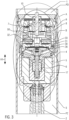
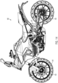
- the drawing shows a sectional view of a telescopic spring fork leg 40 of a motorcycle 80 according to an embodiment of the valve assembly 1.
- the telescopic fork leg 40 has on in the drawing 1 lower end a clamping fist 41 for receiving a quick-release axle 81 of the in 14 the front wheel 82 of the motorcycle 70 shown in the drawing.
- the telescopic spring fork leg 40 is a telescopic spring fork leg designed in an upside-down configuration, in which the compression stage chamber PD is arranged below the valve arrangement 1 in the vertical axis direction H of the telescopic spring fork leg 40 and the rebound stage chamber PZ is arranged above the valve arrangement 1.
- the valve arrangement 1 can also be used in a telescopic spring fork leg, not shown in detail, in which the compression chamber PD is arranged in the vertical axis direction H above the valve arrangement and the rebound chamber PZ is arranged below the valve arrangement 1 .
- the drawing also shows a section II, which is closer based on 2 shown in the drawing.
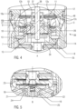
- the valve arrangement 1 can therefore be used, for example, on a vibration damper 42 designed as a telescopic spring fork leg 40, as is shown in 2 the drawing is shown in more detail.
- the vibration damper 42 has a tube 3 and a piston rod 2 which is arranged in an interior space 43 of the tube 3 together with the valve arrangement 1 .
- the interior space 43 is designed to accommodate a damping fluid, not shown in detail, which is fork oil in the illustrated embodiment.
- the rebound chamber PZ and the compression chamber PD are physically separated from the valve assembly 1 but are fluidically connected via the valve assembly 1 for exchanging fork oil, ie for exchanging damping fluid.
- the valve assembly 1 is supported via a spring 44 on a basis of 1 and 2 abutment 45 shown in the drawing.
- valve assembly 1 shows the valve assembly 1 and other components in a position rotated by 180 degrees compared to the installation position of the valve assembly 1 in the telescopic spring fork leg 40 for ease of illustration and explanation.
- the valve assembly 1 has an annular valve seat 16a and has a valve housing 14 which is adapted to receive damping fluid in the form of the fork oil mentioned above.
- the valve assembly 1 has a valve piston 13 on which a main valve 11 is arranged with valve discs 12, which the basis of 13 visible valve disks 12a, 12b and 12c.
- valve disk 12c or support disk 12c is supported on an annular valve seat 16b which is arranged on an upper side of the valve piston 13 .
- the valve arrangement 1 has a passage 27 which acts as a pre-throttle for the rebound stage and also has a passage 26 which acts as a pre-throttle for the compression stage.
- valve disks 12 are arranged on a guide pin 37, namely guided axially movable relative to the valve piston 13 and radially, for which purpose a closer reference to FIG 13
- the sleeve body 10 shown in the drawing is provided, on which the valve disks 12 are guided radially, so that they cannot cant relative to the longitudinal axis 38 of the guide pin 37 and thus relative to the longitudinal axis 38 of the valve arrangement 1 .
- the valve arrangement 1 also has a plurality of non-return valves 7, 8, 9, 10, which will be discussed below, it being mentioned at this point that the sleeve body 10 also acts as a non-return valve.
- the valve arrangement 1 also has a disk spring 15 which is designed to meander, as can be seen from the illustration 13 can be seen in the drawing.
- valve piston 13 is arranged in an interior space 39 of the valve housing 14 in an axially displaceable manner, and a pilot chamber 25 is also formed in the interior space 39, in which a pilot pressure or pilot pressure can be formed.
- the guide pin 37 is arranged on a stop disk 34 and also accommodates the slotted sleeve body 10 on which the valve disks 12 are guided radially and accommodated in an axially displaceable manner.
- valve housing 14 is radially supported in the tube 3 of the vibration damper 42 via a sealing device 46 and sealed.
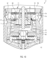
- FIG. 5 The drawing shows the pilot valve B with a sealing body 19 which, in the illustrated embodiment, is in the form of a truncated cone in sections and has an outer cone 47 which is pressed by a spring 20 against an annular valve seat 21 of a discharge valve 24 .
- the drawing shows that the pilot valve B has an electromagnet 4, the armature 17 of which can be displaced in the vertical axis direction H1 by applying current, counter to the action of the valve spring 18.
- the pilot valve B has an operating valve 22, which on the basis of Figure 8a can be seen as a passage opening between a supporting edge 48 of a valve seat 30 and the valve spring 18.
- an operating valve 22 When the pilot valve B is in the de-energized position, a fluid flow induced by the system pressure takes place via the operating valve 22.
- the system pressure ensures via the incompressible fork oil that there is an in 12 the. Fluid flow shown in dashed lines occurs because the emergency valve disk 23 can be opened by the system pressure and a predetermined pressure relief can occur.
- a coil 6 is arranged in the visible housing 5, via which the armature 17 of the electromagnet 4 can be energized in such a way that the valve spring or valve disk 18 can be opened against its spring force and in this way, with increasing energization, the operating valve 22 is closed more continuously against the action of the valve spring 18, thereby generating a higher pressure drop.
- the armature 17 When the electromagnet 4 is energized from the de-energized position to a position supplied with a minimum current, the armature 17 generates a thrust force in the direction of the pilot valve B and opens the drain valve 24 against the action of the force of the spring 20, as a result of which the emergency valve formed by the emergency valve disk 23 is short-circuited.
- the valve spring 18 that can be seen has a recess 49 which is provided for the passage of damping fluid (fork oil).
- the valve seat 30 mentioned above is arranged on the valve spring 18 with the interposition of a spacer washer 28 .
- the cover disk 33 is arranged with the interposition of adjusting disks 31 and an O-ring 32 and is supported on a radially inner collar 50 on the spring disk 15 .
- the non-return valves 7, 8 and the non-return valve 9 as well as the sleeve body 10, which also functions as a non-return valve, ensure that the pilot valve B is always supplied with damping fluid from the pressure-generating side and the damping fluid can flow to the side facing away from the pressure, regardless of the direction of movement of the valve arrangement 1, i.e. regardless of whether there is a compression movement or a rebound movement of the vibration damper 2.
- the spring washer 35 shown acts on the check valve 9 and is fixed by a retaining ring 36.
- the inside 4 apparent sleeve body 10 is based on 13 shown in perspective.
- the sleeve body 10 has a tubular configuration with a wall 51, which is formed by a hollow-cylindrical body 52, which is arranged with an end face seated on a circular base 53 and has opposing recesses 54, which are rectangular in plan view and form a respective slot 77.
- the rectangular recesses 54 or slots 77 serve to accommodate a respective central web 55 of the 13 also shown valve disk 12a, the support disk 12b and the two support disks 12c.
- the respective central webs 55 are received in the recesses 54 and are supported via the spring 29 on the bottom 53 of the sleeve body 10 .
- the valve disc 12a has a contact surface side 74, as is the case, for example, with reference to FIG 9 of the drawing and also a support surface side 75 opposite the contact surface side 74, which is also shown in 9 shown in the drawing, with the valve disk 12a resting in some areas with the contact surface side 75 on the support disk 12b arranged underneath.
- the support disk 12b cannot support the valve disk 12a in the area of the clearances 76 of the support disk 12b.
- the exemptions 76 are at the in 6 and 7 the drawing shown support disc 12b dotted line hatched areas shown. In other words, the areas where the support disk 12b does not support the valve disk 12a.
- the wall 51 is in the form of two cylindrical tube segments, which extend away from the base 53 at right angles thereto.
- the two support disks 12c are designed to be rigid and have two recesses 57 which are provided for receiving the tube segments 56 of the sleeve body 10. In addition, damping fluid can also flow through the two recesses 57 .
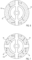
- the support disk 12b shown is based on two embodiments in 6 and 7 shown enlarged in the drawing.
- the drawing shows a first embodiment of the support disk 12b with two projections 58
- 7 the drawing shows a second embodiment of the support disc 12b with four projections 58.
- the support disk 12b shown in a respective top view has a first region 59 which is circular in a top view and in the illustration shown in FIG 6 two second regions 60 extending radially outwards from the outer circumference of the first region 59, which are designed as projections or wings 58 in the illustrated embodiment.
- the in 7 Support disk 12b shown according to the second embodiment has a first circular area 59, from which four second areas 60 extend radially outwards, each of which is designed as a projection or vane 58.
- the respective first region 59 of the support disk 12b has a smaller outside diameter than the valve disk 12a arranged to rest thereon.
- the support disk 12b also has recesses 61 through which the cylindrical tube segments 56 of the sleeve body 10 pass and which are also designed for the passage of damping fluid.
- valve disc 12a has an edge region 62 on the outer peripheral region which is intended to rest against the annular valve seat 16a of the valve housing 14 and also itself from this to form gap spaces between the valve disc 12a and the valve seat 16a and can also be completely separated from the valve seat 16a when the valve piston 13 is moved axially away from the valve seat 16a, as will be explained in more detail below.
- the drawing shows an enlarged sectional view of the valve assembly 1 to show the fluid flow in the compression stage at low speed of the piston rod 2.
- the motorcycle 80 provided with the valve arrangement 1 according to the invention drives over a bump in the ground with the front wheel 82, this leads to a compression movement of the telescopic spring fork leg 40.
- different piston rod speeds of the piston rod 2 can occur.
- the vibration damper 42 can also be used to dampen movements of the rear wheel 83 of the motorcycle 80 .
- the valve assembly 1 attached to the piston rod 2 moves back and forth within the tube 3 filled with damping fluid in the form of, for example, fork oil.
- the valve arrangement 1 also includes the electromagnet 4 described above and, for example, in 4
- the valve assembly 1 shown has the damping fluid flowing through it during a movement both in the compression direction and in the tension direction.
- the movement in the compression direction occurs when the vibration damper 42, which is designed as a telescopic spring fork leg 40 only for the sake of explanation, experiences a compression movement, while the movement in the tension direction occurs when the vibration damper 42 experiences an extension movement or rebound movement.
- compression stage corresponds to the state that occurs during the compression movement
- the moving rebound stage corresponds to the state that occurs during the rebound movement.
- the pressure drop in both directions of movement can be influenced with the aid of the electromagnet 4 via a corresponding displacement movement of the valve disk 18 .
- part of the oil flow resulting from the respective movement is fed to the pilot valve B, which is acted upon by the electromagnet 4 .
- the system of four check valves 7, 8, 9, 10 already described above makes it possible for the pilot valve B to always be supplied with damping fluid from the pressure-generating side and for the damping fluid to flow away to the side facing away from the pressure.
- the pilot pressure generated by the pilot valve B acts on the rear surface of the main valve 11 and thus influences the pressure drop that occurs at the main valve 11 or the valve arrangement 1 .
- the valve piston 13 is sealed against the valve housing 14 with a hydraulic fit and is thereby radial guided and axially supported.
- the valve piston 13 is pressed against the valve seat 16a in the valve housing 14 by means of the disc spring or spring washer 15 .
- the pilot valve B takes the in 12 the safety position shown in the drawing.
- the outer cone 19 is acted upon by the spring 20 against the valve seat 21 of the discharge valve 24 and an oil flow which is set up flows through the open service valve 22 in the direction of the emergency valve formed by the emergency valve disk 23 .
- Energizing electromagnet 4 with a minimum operating current ensures that armature 17 of electromagnet 4 exerts a thrust force in the direction of pilot valve B, opening drain valve 24 against the force of spring 20 and short-circuiting emergency valve 23.
- the operating valve 22 is still in a wide open position and in this way only generates a small drop in pressure. With increasing energization of the electromagnet 4, the operating valve 22 is closed further and thereby generates a higher pressure drop.
- the drawing shows the flow of damping fluid at a low piston rod speed.
- the flow of damping fluid can be seen from the arrows and the dashed lines.
- the main valve 11 remains closed and there is only a slight flow of oil through the main valve 11 instead of by the recesses 63 of the valve disk 12a, the recesses 61 of the support disk 12b and the recesses 57 of the disks 12c are flown through and the damping fluid passes the restrictor 26 and enters the pilot chamber 25 and from there via the service valve ( Figure 8a ) and the open valve seat 21 and the check valve 9 and the housing 14 in the direction of the rebound chamber PZ.
- the course of the damping force labeled II shows the course of the damping force when the support disk 12b is formed with four projections, as shown in the illustration 7
- the course of the damping force denoted by III shows the course of the damping force when the support disk 12b is formed with two projections 58 as shown in FIG 6 shows.
- the 8 illustrated and denoted by the case 65 further flow of damping fluid. Due to the increase in pressure in the compression chamber PD, a portion of the damping fluid still flows via the recesses 63 of the valve disc 12a, the recesses 61 of the support disc 12b and the recesses 57 of the discs 12c, as described above.
- the recesses 63 of the valve disc 12a have an inner recess in the area of the opposite curved outer peripheral areas, which has a larger diameter than the support disc 12b arranged below it in the vertical axis direction of the valve assembly 1 and the edge area 68 of the inner recess lifts off the support disc 12b when pressure is applied with damping fluid in the direction from the interior 39 of the valve housing 14, as is shown in FIG 10 shown in the drawing.
- the pressure rise in the compression chamber PD also ensures that the edge area 62 of the flexible valve disk 12a is lifted off the valve seat 16a to open a gap space between the edge area 62 and the valve seat 16a.
- the support disk 12b has a circular first area 59, which is smaller than the outer diameter of the valve disk 12a, and the valve disk 12a on the support disk 12b outside of the first area 59 only rests on the projections 58, but these are not present along the entire circumferential extent of the circular first area 59, the valve disk 12a can relative to the support disk 12b at the projections 58 deform from below supported areas similar to a spring washer and in this way forms between the edge portion 62 of the valve disc 12a and the annular Valve seat 16a along a partial peripheral area of the valve disk 12a and an oil flow symbolized by the arrow 65 takes place directly via the channel 64 in the direction of the rebound stage chamber PZ.
- the configuration according to the invention of the valve arrangement 1 with the support disk 12b, which has radially outwardly projecting projections 58, which only partially support the valve disk 12a on the contact side of the valve disk 12a on the support disk 12b, means that the valve disk 12a can open a gap space or gap spaces to the annular valve seat 16a at a time when others in the circumferential direction of the edge region 62 of the valve disk 1 2a running other edge regions, namely those that are supported or supported by the projections 58 of the support disk 12b, still rest on the valve seat 16a.
- the drawing shows a diagram to explain the course of the volume flow of damping fluid and the pressure course plotted against time.
- the pressure profile denoted by P1 occurs as a result of the volume flow of damping fluid through the valve arrangement 1, denoted by Q1.
- the oscillating pressure profile is eliminated, as is the loss of comfort associated with the known valve assembly.
- valve disks 12 of the main valve i.e. the valve disk 12a, the support disk 12b and the bearing disks 12c, are completely released from the valve seat 16a, as is shown in Fig 9 shown in the drawing.
- the counterforce on the back of the main valve 11 is determined by the pressure-loaded area of the valve piston 13 multiplied by the pressure that is built up by the pilot valve B and the force of the spring 15.
- the flexible valve disk 12a can release a passage cross section at the annular valve seat 16a depending on the pressure, even if the main valve 11 is not yet fully open, since the above-described equilibrium of forces has not yet been reached.
- This configuration ensures a constant opening behavior of the main valve 11 according to the curve II, III in 16 according to segment "B".
- the piston rod 2, on which the valve arrangement 1 is arranged moves out out of the area of the compression chamber PD in the direction of the rebound chamber PZ. This movement leads to an increase in the system pressure in the rebound chamber and thus to a flow of oil in the direction of the compression chamber.
- the drawing shows an enlarged sectional view of the valve assembly 1 to show the fluid flow in the rebound at low and medium speed of the piston rod, which occurs during the rebound movement.
- the main valve 11 remains closed with the valve discs 12 and an oil flow takes place via the pilot valve B, which in turn corresponds to the curve according to segment "A". 16 .
- Damping fluid flows from the rebound chamber via the restrictor 27 of the main valve 11 and the check valve 7, which opens due to the system pressure, into the pilot chamber 25 of the pilot valve B and from there via the pilot valve B and the housing 14 or the oil channel 66 and the recesses 57, 61 and 63 (see Fig 13 ), towards the compression chamber PD.
- the sleeve body 10 is designed in such a way that it holds the valve disc 12a and the support disc 12b and the stop discs 12c in a mutually aligned position. This is achieved in that the sleeve body 10 with its cylindrical tube segments 56 passes through the respective recesses 57, 61 and 63 of the disks 12a, 12b, 12c and thus ensures that the disks are arranged such that they cannot rotate relative to one another.
- the cross-sectional area of the respective recesses 57, 61 and 63 of the stacked discs thus remains constant and it is avoided that central webs 55 of the discs 12a, 12b, 12c can twist relative to one another, which would lead to a change in the cross-sectional area through which flow can take place.
- the predetermined effective flow cross section formed by the recesses is thus retained in a predetermined manner.
- This function of the sleeve body 10 would also be retained in the case of a possible embodiment of the support disk 12b as a full-surface disk without any cut-outs.
- the increase in system pressure leads to a lifting movement of the radially inner area 69 of the valve disk 12a from the supporting disk 12b, since the system pressure can penetrate into the intermediate space 70 between the underside of the valve disk 12a and the upper side of the first underlying supporting disk 12c, since this intermediate space is not closed by the outer peripheral area of the supporting disk 12b, since this is not formed over the entire surface in this area, but has gaps 76 and the valve disk 12a at the Top of the support disc 12b rests only in the area of the projections 58.
- the resulting oil flow 71 allows the system pressure to relax and a sudden or abrupt or jerky lifting of the valve disks 12 (ie the valve disk 12a, support disk 12b, bearing disks 12c) from the annular valve seat 16a is avoided.
- the second or lower thrust washer 12c still abuts the annular valve seat 16b, as illustrated in FIG 10 can be seen in the drawing.
- valve disc 12a continues to abut annular valve seat 16a.
- the increasing system pressure leads to the main valve 11 opening, since the counterforce acting on the back of the valve piston 13 is exceeded and the annular valve seat 16b opens, since the valve piston 13 detaches with its control edge 72 from the support disk 12c and thus releases the gap space which allows damping fluid to pass through in accordance with the arrow 73 11 the drawing leads.
- the counterforce acting on the valve piston 13 is determined from the pressure-loaded area of the rear side of the valve piston 13 multiplied by the pressure that is built up by the pilot valve B and the pretensioning force of the Woodruff key 15.
- the gap space between the control edge 72 and the bearing disk 12c opens and oil flow can take place through the recesses 57, 61 and 63 in the bearing disks 12c, support disk 12b and the valve disk 12a, as illustrated by the oil flow arrow 73 11 shown in the drawing.
- the valve arrangement according to the invention can therefore also release the passage cross section of the main valve 11 during the rebound movement depending on the system pressure, even if the main valve 11 has not yet lifted off the annular valve seat 16 .
- This also contributes to a constant opening behavior of the main valve in the area of segment "B" during the rebound movement, i.e. at medium damper speeds or piston rod speeds, and the course of the damper force plotted against the damper speed can be influenced by the design of the support disk 12b with two or more projections 58.
- the configuration of the support disk 12b with two projections or wings 58 leads to a more linear curve III of the damping force plotted against the damper speed in the range of medium piston rod speeds, while the design of the support disk 12b with four projections or wings 58 leads to a slightly rounded curve II of the damping force. 16 .
- Drawing shows the course of the damping force over the damper speed with a high current supply to the electromagnet 4 and the course of the respective curves II, III can be changed by changing the current applied to the coil 6 of the electromagnet 4 accordingly.
Landscapes
- Engineering & Computer Science (AREA)
- General Engineering & Computer Science (AREA)
- Mechanical Engineering (AREA)
- Fluid-Damping Devices (AREA)
Description
Die vorliegende Erfindung betrifft eine Ventilanordnung für einen Schwingungsdämpfer nach dem Oberbegriff des Anspruchs 1. Die Erfindung betrifft darüber hinaus einen Schwingungsdämpfer nach dem Anspruch 12 und ein Fahrzeug mit einem solchen Schwingungsdämpfer nach Anspruch 13. Die
Bei dem Schwingungsdämpfer kann es sich beispielsweise um ein Teleskopfedergabelbein eines Motorrads handeln oder auch um einen Stoßdämpfer für ein mehr als einspuriges Fahrzeug, also beispielsweise einen Personenkraftwagen, der Schwingungsdämpfer kann auch für die Anwendung im industriellen Bereich vorgesehen sein. Zur Beeinflussung des Dämpfungsverhaltens eines solchen Schwingungsdämpfers kann die Ventilanordnung ein Pilotventil aufweisen, welches als Druckregler fungiert. Die Dämpfereinrichtung oder der Schwingungsdämpfer besitzt üblicherweise zwei Fluidkammern, zwischen denen Dämpfungsfluid ausgetauscht wird. Bei den Fluidkammern handelt es sich um eine erste Kammer oder Druckstufenkammer und eine zweite Kammer oder Zugstufenkammer. Aus der Druckstufenkammer strömt beim Einfedervorgang der Dämpfereinrichtung Dämpfungsfluid in Richtung zur zweiten Kammer oder Zugstufenkammer. Beim Ausfedervorgang oder Rebound strömt Dämpfungsfluid von der Zugstufenkammer in Richtung zur Druckstufenkammer, wobei das Dämpfungsfluid jeweils die Ventilanordnung durchströmt, mit deren Hilfe Dämpfungsarbeit geleistet wird und die die Dämpfereinrichtung beaufschlagenden Schwingungsamplituden bedämpft werden.The vibration damper can be, for example, a telescopic spring fork leg of a motorcycle or a shock absorber for a vehicle with more than one track, for example a passenger car. The vibration damper can also be provided for use in the industrial sector. In order to influence the damping behavior of such a vibration damper, the valve arrangement can have a pilot valve which acts as a pressure regulator. The damping device or the vibration damper usually has two fluid chambers, between which damping fluid is exchanged. The fluid chambers are a first chamber or compression chamber and a second chamber or rebound chamber. During the compression process of the damper device, damping fluid flows out of the compression chamber in the direction of the second chamber or rebound chamber. During the rebound process or rebound, damping fluid flows from the rebound stage chamber in the direction of the compression stage chamber, with the damping fluid flowing through the valve arrangement, with the help of which damping work is performed and the vibration amplitudes acting on the damper device are damped.
Mit dem Pilotventil kann das Öffnungsverhalten der Ventilanordnung oder vorgesteuerten Ventils beeinflusst werden und zwar dadurch, dass in einer Vorsteuerkammer ein Steuerdruck aufgebaut wird, der auf den Ventilkolben des Hauptventils oder einer am Ventilkolben angeordneten Ventilanordnung wirkt.The pilot valve can be used to influence the opening behavior of the valve arrangement or pilot-operated valve by building up a control pressure in a pilot chamber, which acts on the valve piston of the main valve or a valve arrangement arranged on the valve piston.
Die Dämpferkraft verändert sich mit der Geschwindigkeit der Bewegung der Kolbenstange, an welcher der Ventilkolben angeordnet ist.The damping force changes with the speed of movement of the piston rod on which the valve piston is arranged.
Wenn das mit einem Schwingungsdämpfer mit einem vorgesteuerten Ventil versehene Fahrzeug eine Bodenunebenheit überfährt, führt dies zu einer Bewegung der Kolbenstange mit einer bestimmten Geschwindigkeit. Steigt diese Geschwindigkeit beispielsweise in Abhängigkeit der Höhe der Kraftbeaufschlagung, welche die Kolbenstange erfährt, führt dies zu einer höheren Dämpferkraft und das am Ventilkolben angeordnete Hauptventil öffnet dann ruckartig oder schlagartig und es kommt zu einem scharfen Knick im Diagramm der Dämpferkraft aufgetragen über der Kolbenstangengeschwindigkeit oder Dämpfergeschwindigkeit. Dieses scharfe Abknicken der Kraftkennlinie aufgetragen über der Dämpfergeschwindigkeit macht sich bei der Fahrt des Fahrzeugs in der Form einer Komforteinbuße bemerkbar, welche bei einem mit einem vorgesteuerten Ventil versehenen Schwingungsdämpfer oftmals zu beobachten ist.When the vehicle equipped with a vibration damper with a pilot operated valve drives over a bump, this causes the piston rod to move at a certain speed. If this speed increases, for example depending on the amount of force applied to the piston rod, this leads to a higher damping force and the main valve arranged on the valve piston then opens suddenly or abruptly and there is a sharp kink in the diagram of the damping force plotted against the piston rod speed or damper speed. This sharp break in the force characteristic plotted against the damper speed becomes noticeable when the vehicle is driving in the form of a loss of comfort, which can often be observed with a vibration damper provided with a pilot-controlled valve.
Anhand der
Darüber hinaus weist diese bekannte Ventilanordnung den Nachteil auf, dass der scheibenförmige Ventilkörper an der Innenausnehmung des Ventilgehäuses mit einem radial außen liegenden Bereich des Ventilkörpers anliegt. Der Ventilkörper in der Form einer Ventilscheibe ist daher im Gehäuse außen geführt. Wenn sich der Ventilkörper in der von den Steuerkanten abgehobenen Stellung befindet und die Reboundbewegung einsetzt, wird der scheibenförmige Ventilkörper von der Oberseite her vom Dämpfungsfluid mit Druck beaufschlagt. Diese Druckbeaufschlagung führt dazu, dass sich der Ventilkörper relativ zur Innenausnehmung schräg stellt und verkantet und daher eine undefinierte Stellung einnimmt.In addition, this known valve arrangement has the disadvantage that the disk-shaped valve body bears against the inner recess of the valve housing with a radially outer area of the valve body. The valve body in the form of a valve disk is therefore guided outside in the housing. When the valve body is in the position lifted from the control edges and the rebound movement begins, the disc-shaped valve body is subjected to pressure from the top side by the damping fluid. This pressurization leads to the valve body being inclined and tilted relative to the inner recess and therefore assuming an undefined position.
Ausgehend hiervon liegt der vorliegenden Erfindung die Aufgabe zugrunde, eine Ventilanordnung bereitzustellen, welche einerseits das Problem des Verkantens der Ventilscheibe beseitigt und andererseits sowohl bei der Einfederbewegung als auch bei der Reboundbewegung ein sanftes und gleichmäßiges Öffnen des Hauptventils ermöglicht. Auch soll ein Schwingungsdämpfer bereitgestellt werden, der einen komfortablen Übergang von der Einfederbewegung zur Reboundbewegung bereitstellt. Auch soll ein Fahrzeug mit einem solchen Schwingungsdämpfer bereitgestellt werden.Proceeding from this, the present invention is based on the object of providing a valve arrangement which on the one hand eliminates the problem of tilting of the valve disk and on the other hand both during the compression movement and during the rebound movement allows the main valve to open smoothly and evenly. A vibration damper is also to be provided which provides a comfortable transition from the compression movement to the rebound movement. A vehicle with such a vibration damper is also to be provided.
Die Erfindung weist zur Lösung dieser Aufgabe hinsichtlich der Ventilanordnung die im Patentanspruch 1 angegebenen Merkmale auf. Vorteilhafte Ausgestaltungen hiervon sind in den weiteren Ansprüchen beschrieben. Darüber hinaus weist die Erfindung hinsichtlich des Schwingungsdämpfers die im Patentanspruch 12 angegebenen Merkmale auf. Hinsichtlich des bereitzustellenden Fahrzeugs weist die Erfindung die im Patentanspruch 13 angegebenen Merkmale auf.To solve this problem, the invention has the features specified in
Die Erfindung schafft eine Ventilanordnung für einen Schwingungsdämpfer, mit einem einen ringförmigen Ventilsitz aufweisenden und zur Aufnahme von Dämpfungsfluid vorgesehenen Ventilgehäuse und einem Ventilkolben, der in einem Innenraum des Ventilgehäuses relativ zum Ventilsitz axial verschiebbar angeordnet ist und der Ventilkolben ein Hauptventil aufweist, welches eine flexible kreisförmige Ventilscheibe aufweist, die mit einer Anlageflächenseite an dem Ventilsitz lösbar in Anlage bringbar ist und die Ventilscheibe mittels eines Führungsstifts am Ventilkolben relativ zu diesem axial bewegbar und radial geführt angeordnet ist und die Ventilanordnung einen Elektromagneten mit einem Anker zur Beaufschlagung eines Pilotventils aufweist, wobei an der von der Anlageflächenseite der Ventilscheibe abgewandten Auflageflächenseite der Ventilscheibe eine flexible Stützscheibe angeordnet ist, an der die Ventilscheibe entlang eines sich in Umfangsrichtung der Ventilscheibe erstreckenden Teilumfangbereichs aufliegt.The invention provides a valve arrangement for a vibration damper, with a valve housing that has an annular valve seat and is provided for receiving damping fluid, and a valve piston that is arranged in an interior space of the valve housing so that it can be displaced axially relative to the valve seat, and the valve piston has a main valve that has a flexible, circular valve disk that can be brought into detachable contact with a contact surface side on the valve seat, and the valve disk is arranged by means of a guide pin on the valve piston so that it can be moved axially relative to it and is guided radially, and the valve arrangement has an electromagnet an armature for acting on a pilot valve, a flexible support disk being arranged on the contact surface side of the valve disk facing away from the contact surface side of the valve disk, on which flexible support disk the valve disk rests along a partial peripheral region extending in the circumferential direction of the valve disk.
Die Stützscheibe liegt also an der Ventilscheibe an und unterstützt diese bei einer Druckbeaufschlagung oder Kraftbeaufschlagung der Ventilscheibe in Richtung zur Stützscheibe. Dadurch, dass die Ventilscheibe aber nur entlang eines in Umfangsrichtung der Ventilscheibe betrachtet sich erstreckenden Teilumfangbereichs an der Stützscheibe aufliegt, besitzt die Ventilscheibe in Umfangsrichtung betrachtet Teilbereiche oder Segmente oder Flächenbereiche, an denen die Stützscheibe bei einer Druckbeaufschlagung der Ventilscheibe in Richtung zur Stützscheibe die Ventilscheibe nicht in Gegenrichtung zur die Ventilscheibe beaufschlagenden Kraftrichtung unterstützen kann, also in den genannten Bereichen keine die Ventilscheibe abstützende Kraft aufnehmen kann, also keine Widerlagerkraft aufbauen kann, was dazu führt, dass sich die Ventilscheibe in diesen nicht von der Stützscheibe unterstützten Bereichen durchbiegt oder verformt.The support disk is therefore in contact with the valve disk and supports it when pressure is applied or force is applied to the valve disk in the direction of support washer. However, because the valve disk rests on the supporting disk only along a partial circumferential region that extends in the circumferential direction of the valve disk, the valve disk has partial regions or segments or surface regions, viewed in the circumferential direction, on which the supporting disk cannot support the valve disk in the opposite direction to the direction of force acting on the valve disk when pressure is applied to the valve disk in the direction of the supporting disk, i.e. in the areas mentioned it cannot absorb any force supporting the valve disk, i.e. cannot build up an abutment force, which causes the valve to deflect disc bends or deforms in these areas not supported by the support disc.
In den vorstehend erwähnten Teilbereichen oder Segmenten oder Flächenbereichen der Ventilscheibe, an denen diese also nicht an der Stützscheibe aufliegt, führt die Beaufschlagung der Ventilscheibe über das Dämpfungsfluid mit einem Dämpfungsdruck dazu, dass sich die Ventilscheibe im Bereich der Teilbereiche oder Segmente oder Flächenbereiche infolge der Kraftbeaufschlagung durch den Dämpfungsdruck verformen oder verbiegen kann.In the above-mentioned sub-areas or segments or surface areas of the valve disk, where it does not rest on the support disk, the application of a damping pressure to the valve disk via the damping fluid means that the valve disk can deform or bend in the area of the sub-areas or segments or surface areas as a result of the force applied by the damping pressure.
Infolgedessen löst sich die Ventilscheibe infolge der Kraftbeaufschlagung an den verformten Teilbereichen oder Segmenten oder Flächenbereichen aus der Anlage an dem ringförmigen Ventilsitz, an dem die Ventilscheibe im unbelasteten Zustand flächig anliegt und es kommt infolgedessen, dass sich die Ventilscheibe bereichsweise vom Ventilsitz abhebt, dazu, dass ein Spaltraum zwischen den verformten Bereichen der Ventilscheibe und dem Ventilsitz entsteht und Dämpfungsfluid durch den Spaltraum hindurch treten kann und somit Dämpfungsarbeit geleistet wird.As a result, as a result of the application of force to the deformed sub-areas or segments or surface areas, the valve disc detaches from the contact with the annular valve seat on which the valve disc lies flat in the unloaded state and as a result the valve disc lifts off the valve seat in areas, resulting in a gap space between the deformed areas of the valve disc and the valve seat and damping fluid can pass through the gap space and damping work is thus performed.
Bei einem bekannten vorgesteuerten Ventil liegt die Ventilscheibe des Hauptventils an dem ringförmigen Ventilsitz vollflächig auf und zwar so lange, bis der Hauptkolben oder Ventilkolben infolge der Druckbeaufschlagung der Ventilscheibe oder des Hauptkolbens eine geringfügige Bewegung in Kraftrichtung der Druckbeaufschlagung ausführt. Dies führt zu einer ruckartigen oder schlagartigen Abhubbewegung der Ventilscheibe vom Ventilsitz und es kommt aufgrund der Massenträgheit des Hauptkolbens zu einer Bewegung des Hauptkolbens zusammen mit der Ventilscheibe in Kraftrichtung um einen Wegbetrag, der größer ist als es der resultierenden Kraftdifferenz zwischen der die Ventilscheibe und/oder den Hauptkolben beaufschlagenden Druckkraft und der Gegenkraft, die vom Druck in der Vorsteuerkammer des Pilotventils herrührt, entspricht. Es findet also ein Überschwingen statt.In a known pilot-operated valve, the valve disc of the main valve lies on the annular valve seat over its entire surface, namely until the main piston or Valve piston performs a slight movement in the direction of force of pressurization due to the pressurization of the valve disc or the main piston. This leads to a jerky or abrupt lifting movement of the valve disc from the valve seat and, due to the mass inertia of the main piston, the main piston moves together with the valve disc in the direction of the force by a distance that is greater than the resulting force difference between the pressure force acting on the valve disc and/or the main piston and the counterforce that comes from the pressure in the pilot chamber of the pilot valve. So there is an overshoot.
Aufgrund dieser Überschwingbewegung des Hauptkolbens in Richtung zur Vorsteuerkammer des Pilotventils steigt dann der Druck in der Vorsteuerkammer entsprechend an, was zu einer Gegenbewegung des Hauptkolbens mit dem Hauptventil führt, sodass sich ein zeitabhängiger oszillierender Schwingungsverlauf im Systemdruckverlauf aufgetragen über der Zeit einstellt mit der Folge des vorstehend bereits erwähnten Komfortverlusts.Due to this overshooting movement of the main piston in the direction of the pilot chamber of the pilot valve, the pressure in the pilot chamber then increases accordingly, which leads to a counter-movement of the main piston with the main valve, so that a time-dependent oscillating oscillation curve occurs in the system pressure curve plotted over time, with the result of the aforementioned loss of comfort.
Die erfindungsgemäße Lösung schafft hier Abhilfe, indem das Öffnungsverhalten des Hauptventils so beeinflusst wird, dass bereits zu einem Zeitpunkt, bevor sich ein Kräftegleichgewicht zwischen der das Hauptventil beaufschlagenden Druckkraft und der Gegenkraft aufgrund des Pilotdrucks sowie etwaiger zusätzlicher Federkraftkomponenten einstellt - zu einem solchen Zeitpunkt würde sich das Hauptventil öffnen, indem es sich vom Ventilsitz abhebt - sich das Hauptventil zu öffnen beginnt, also ein Volumenstrom an Dämpfungsfluid durch das Hauptventil zu strömen beginnt. Dieser Volumenstrom stellt sich aufgrund der bereichsweisen oder abschnittsweisen Abhubbewegung der Ventilscheibe vom Ventilsitz im Bereich der nicht von der Stützscheibe unterstützten Flächen der Ventilscheibe ein.The solution according to the invention provides a remedy here by influencing the opening behavior of the main valve in such a way that the main valve begins to open, i.e. a volume flow of damping fluid begins to flow through the main valve, at a point in time before a force equilibrium between the pressure force acting on the main valve and the counterforce due to the pilot pressure and any additional spring force components is established - at such a point in time the main valve would open by lifting off the valve seat. This volume flow occurs due to the lifting movement of the valve disk from the valve seat in certain areas or in sections in the area of the surfaces of the valve disk that are not supported by the supporting disk.
Dadurch wird ein ruckartiges oder schlagartiges Öffnen des Hauptventils vermieden, der vorstehend beschriebene oszillierende Schwingungsverlauf im Systemdruck wird vermieden und ebenso wird die geschilderte Komforteinbuße vermieden.As a result, a jerky or abrupt opening of the main valve is avoided, the oscillating oscillation profile in the system pressure described above is avoided and the described loss of comfort is also avoided.
Es ist nach einer Weiterbildung der Erfindung vorgesehen, dass die Stützscheibe in Umfangsrichtung mindestens eine Freistellung aufweist, an der die Ventilscheibe frei ist von einer Unterstützung durch die Stützscheibe und sich die Ventilscheibe bei einer Druckbeaufschlagung in Richtung der Stützscheibe im Bereich der Freistellung stärker durchbiegt als im Bereich der Stützscheibe ohne Freistellung.According to a development of the invention, it is provided that the support disk has at least one clearance in the circumferential direction at which the valve disk is not supported by the support disk and the valve disk bends more when pressure is applied in the direction of the support disk in the area of the clearance than in the area of the support disk without clearance.
Mit der mindestens einen Freistellung des Stützscheibe in deren Umfangsrichtung wird erreicht, dass sich zwischen der Stützscheibe und der Ventilscheibe bei einer Druckbeaufschlagung durch den sich in der Ventilanordnung beziehungsweise in der Druckstufenkammer oder der Zugstufenkammer einstellenden Systemdruck im Bereich der Freistellung und geringfügig benachbart dazu keine Stützkraft zwischen der Stützscheibe und der Ventilscheibe einstellt und sich somit die Ventilscheibe aufgrund der Druckbeaufschlagung relativ zur Stützscheibe verbiegen oder durchbiegen oder verformen kann und sich somit ein Spaltraum zwischen der Ventilscheibe und dem Ventilsitz öffnet, durch den Druck entspannt werden kann und Dämpfungsfluid strömen kann und somit Dämpfungsarbeit geleistet werden kann.With the at least one release of the support disk in its circumferential direction, it is achieved that when pressure is applied by the system pressure occurring in the valve arrangement or in the compression chamber or the rebound chamber in the area of the release and slightly adjacent thereto, no support force is established between the support disk and the valve disk and the valve disk can therefore bend or sag or deform relative to the support disk and thus a gap space between the valve disk and the valve seat opens, can be relaxed by the pressure and damping fluid can flow and thus damping work can be done.
Bei der Freistellung kann es sich also um einen Bereich oder Flächenbereich oder Abschnitt oder Segment der Stützscheibe handeln, an dem diese nicht an der Ventilscheibe anliegt und sich somit die Ventilscheibe relativ zur Stützscheibe verbiegen oder verformen oder durchbiegen kann und sich somit ein Spaltraum zwischen der Ventilscheibe und einem Abschnitt oder Flächenbereich oder Segment einer Dichtfläche einstellt, an der die Ventilscheibe anliegt oder zur Anlage gebracht werden kann. Bei der Dichtfläche kann es sich um den vorstehend erwähnten ringförmigen Ventilsitz handeln oder einer anderen Dichtfläche, welche sich zwischen der Ventilscheibe und einem anderen Bauteil einstellt.The exemption can therefore be an area or surface area or section or segment of the support disk on which it does not rest against the valve disk and the valve disk can therefore bend or deform or bend relative to the support disk and thus a gap space is created between the valve disk and a section or surface area or segment of a sealing surface on which the valve disk rests or can be brought into contact. The sealing surface may be the annular valve seat mentioned above or another sealing surface that occurs between the valve disc and another component.
Die Ventilscheibe kann also im Bereich der Freistellung einen Durchfluss an Dämpfungsfluid bereitstellen, noch bevor die den Hauptkolben beaufschlagenden Kräfte zu einer Verlagerungsbewegung des Hauptkolbens führen, welche zu einem vollständigen Öffnen des Hauptventils am Hauptkolben führen. Wenn dann die den Hauptkolben beaufschlagenden Kräfte zu einer Verlagerungsbewegung des Hauptkolbens und damit zu einer Öffnungsbewegung des am Hauptkolben vorgesehenen Hauptventils führen, findet unmittelbar vor dem Abheben des Hauptventils vom Ventilsitz schon ein Durchfluss an Dämpfungsfluid im Bereich zwischen der Ventilscheibe des Hauptventils und dem Ventilsitz statt, sodass der Durchfluss an Dämpfungsfluid nicht unmittelbar mit dem Abheben des Hauptventils vom Ventilsitz einsetzt oder startet und auf diese Weise die vorstehend beschriebene Überschwingbewegung des Hauptkolbens vermieden wird.The valve disk can therefore provide a flow of damping fluid in the area of the clearance even before the forces acting on the main piston lead to a displacement movement of the main piston, which leads to a complete opening of the main valve on the main piston. If the forces acting on the main piston then lead to a displacement movement of the main piston and thus to an opening movement of the main valve provided on the main piston, a flow of damping fluid takes place in the area between the valve disc of the main valve and the valve seat immediately before the main valve is lifted from the valve seat, so that the flow of damping fluid does not begin or start immediately when the main valve is lifted from the valve seat and in this way the above-described overshooting movement of the main piston is avoided.
Es ist nach einer Weiterbildung der Erfindung auch vorgesehen, dass die Stützscheibe einen in einer Draufsichtansicht kreisförmig ausgebildeten ersten Bereich mit einem ersten Durchmesser aufweist, welcher kleiner ist als der Außendurchmesser der Ventilscheibe und sich vom Außenumfang des ersten Bereichs ausgehend mindestens ein, einen zweiten Durchmesser oder eine zweite Erstreckung aufweisender zweiter Bereich radial nach außen gerichtet erstreckt, welcher sich entlang eines Teilbereichs des Umfangs der Stützscheibe in Umfangsrichtung der Stützscheibe erstreckt.According to a development of the invention, it is also provided that the support disk has a circular first area in a plan view with a first diameter, which is smaller than the outer diameter of the valve disk and, starting from the outer circumference of the first area, at least one second area, which has a second diameter or a second extension, extends radially outwards, which extends along a partial area of the circumference of the support disc in the circumferential direction of the support disc.
Damit weist die Stützscheibe in einer Draufsichtansicht einen kreisförmig ausgebildeten ersten Bereich auf. Von diesem ersten Bereich ausgehend erstreckt sich mindestens ein zweiter Bereich nach außen weg, der am Außenrand von der Mitte der Stützscheibe aus betrachtet eine Außenabmessung aufweist, die betragsmäßig größer ist als der Durchmesser des ersten Bereichs.Thus, in a plan view, the supporting disc has a circular first area. Starting from this first area, at least one second area extends outwards, which has an external dimension on the outer edge, viewed from the center of the support disk, which is larger in absolute terms than the diameter of the first area.
Obwohl vorstehend von einer Stützscheibe mit einem kreisförmig ausgebildeten ersten Bereich gesprochen wurde, kann diese Stützscheibe auch eine von der Kreisform abweichende Außenkonfiguration aufweisen, also beispielsweise rechteckförmig, in der Form eines Mehrecks, oval, als Ellipsoid oder dergleichen ausgebildet sein. Vom Außenumfangsbereich des ersten Bereichs erstreckt sich dann ein zweiter Bereich oder eine zweite Erstreckung in Richtung nach außen weg, dessen Außenrand von der Mitte oder dem Zentrum der Stützscheibe aus betrachtet einen größeren Abstand zur Mitte oder dem Zentrum besitzt. Dieser zweite Bereich weist dann in Außenumfangsrichtung des ersten Bereichs eine geringere Erstreckung auf als der Außenumfangsbereich des ersten Bereichs.Although a support disk with a circular first area was mentioned above, this support disk can also have an external configuration that deviates from the circular shape, for example, be rectangular, polygonal, oval, ellipsoid or the like. A second region or extension then extends outwards from the outer peripheral region of the first region, the outer edge of which has a greater distance to the center or center when viewed from the center or center of the support disc. This second area then has a smaller extent in the outer peripheral direction of the first area than the outer peripheral area of the first area.
Bei dem zweiten Bereich kann es sich beispielsweise um einen sich vom ersten Bereich in der Form eines Flügels oder Lappens weg erstreckenden Bereich handeln. An dem Außenumfangsbereich des ersten Bereichs kann mehr als ein solcher zweiter Bereich vorgesehen sein, beispielsweise also zwei solche zweiten Bereiche, welche sich von der Mitte oder dem Zentrum der Stützscheibe aus betrachtet einander gegenüberliegen oder auch winkelig zueinander versetzt sind.The second region may be, for example, a region extending away from the first region in the shape of a wing or lobe. More than one such second region can be provided on the outer peripheral region of the first region, for example two such second regions which, viewed from the middle or the center of the supporting disc, are opposite one another or are angularly offset from one another.
Es ist nach einer Weiterbildung der Erfindung auch vorgesehen, dass die Stützscheibe mindestens zwei sich radial nach außen erstreckende, einander gegenüberliegende Auskragungen aufweist, welche von der Mitte der Stützscheibe aus betrachtet eine Radialerstreckung kleiner oder gleich dem Außendurchmesser der Ventilscheibe aufweisen.According to a further development of the invention, it is also provided that the support disk has at least two radially outwardly extending, opposite projections which, viewed from the center of the support disk, have a radial extension that is less than or equal to the outer diameter of the valve disk.
Mit einer solchen Konfiguration wird erreicht, dass die an der Stützscheibe aufliegende Ventilscheibe im Bereich des ersten Bereichs der Stützscheibe bei einer Kraftbeaufschlagung durch Dämpfungsfluid in Richtung zur Stützscheibe vom ersten Bereich abgestützt wird, und auch die Bereiche der Ventilscheibe, welche an den Auskragungen der Stützscheibe aufliegen, von der Stützscheibe abgestützt werden, wohingegen diejenigen Bereiche der Ventilscheibe, welche außerhalb des ersten Bereichs der Stützscheibe liegen und auch nicht auf den Auskragungen der Stützscheibe aufliegen, sich bei einer Kraftbeaufschlagung durch Dämpfungsfluid weitgehend frei verformen oder durchbiegen können. Diese sich verformenden oder durchbiegenden Bereiche der Ventilscheibe liegen dann auch nicht mehr an einer Dichtfläche an, an denen die sich nicht durchbiegenden Bereiche der Ventilscheibe noch anliegen.With such a configuration it is achieved that the valve disk resting on the support disk is supported in the region of the first region of the support disk by the first region when a force is applied by damping fluid in the direction of the support disk, and also the regions of the valve disk which are on the projections resting on the support disk are supported by the support disk, whereas those areas of the valve disk which lie outside the first area of the support disk and also do not rest on the projections of the support disk can largely freely deform or bend when a force is applied by damping fluid. These deforming or deflecting areas of the valve disk are then also no longer in contact with a sealing surface on which the non-deflecting areas of the valve disk are still in contact.
Dadurch, dass sich auf diese Weise die Ventilscheibe nur entlang eines Teilbereichs ihres Außenumfangs von der Dichtfläche abhebt, findet ein Volumenstrom an Dämpfungsfluid entlang der sich von der Dichtfläche abhebenden Bereiche statt. Die Ventilscheibe nimmt also eine Konfiguration ähnlich einer gewölbten Federscheibe an.Due to the fact that the valve disk only lifts off the sealing surface along a partial area of its outer circumference in this way, a volume flow of damping fluid takes place along the areas that lift off from the sealing surface. The valve disc thus assumes a configuration similar to a domed spring washer.
Es ist nach einer Weiterbildung der Erfindung vorgesehen, dass die Ventilanordnung mindestens eine Auflagerscheibe aufweist, an der die Stützscheibe mit ihrer von der Ventilscheibe abgewandten Seite aufliegt.According to a development of the invention, it is provided that the valve arrangement has at least one bearing disk, on which the supporting disk rests with its side facing away from the valve disk.
Diese Auflagerscheibe ist steifer ausgebildet als die Ventilscheibe und/oder die Stützscheibe, sodass die Stützscheibe durch die Auflagerscheibe bei einer Druckbeaufschlagung der Ventilscheibe in Richtung der Stützscheibe durch die Auflagerscheibe abgestützt wird. Die Auflagerscheibe nimmt also die Druckkraft auf, welche durch die Druckbeaufschlagung der Ventilscheibe mit Dämpfungsdruck in Richtung der Stützscheibe auf die Ventilscheibe und damit die Stützscheibe wirkt. Mit der Auflagerscheibe wird auch eine Überlastung der Ventilscheibe und/oder der Stützscheibe vermieden, da sich die nicht von der Stützscheibe unterstützten Bereiche der Ventilscheibe bei einer Druckbeaufschlagung nur soweit in Richtung zur Auflagerscheibe verbiegen oder verformen können, bis die gebogenen oder verformten Bereiche der Ventilscheibe an der biegesteif ausgebildeten Auflagerscheibe in Anlage kommen.This support disk is stiffer than the valve disk and/or the support disk, so that the support disk is supported by the support disk when pressure is applied to the valve disk in the direction of the support disk. The support disk thus absorbs the compressive force which, as a result of the pressure being applied to the valve disk with damping pressure in the direction of the support disk, acts on the valve disk and thus the support disk. The support disk also avoids overloading of the valve disk and/or the support disk, since the areas of the valve disk that are not supported by the support disk can only bend or deform when pressure is applied in the direction of the support disk until the bent or deformed areas of the valve disk come into contact with the support disk, which is designed to be rigid.
Die Ventilscheibe ist biegeweich ausgebildet, sodass sie sich im Bereich der Freistellung oder der Freistellungen der Stützscheibe bei einem Anstieg des Dämpfungsdrucks leicht verformen kann und einen Spaltraum oder Spalträume zum Durchtritt von Dämpfungsfluid freigeben kann. In Abhängigkeit der Geschwindigkeit der Bewegung der Kolbenstange kann der die Ventilscheibe beaufschlagende Dämpfungsdruck hohe Werte aufweisen, was zu einer etwaigen Überbelastung der biegeweichen Ventilscheibe führen könnte.The valve disk is designed to be flexible, so that it can easily deform in the area of the release or releases of the support disk when the damping pressure increases and can release a gap space or gaps for the passage of damping fluid. Depending on the speed of movement of the piston rod, the damping pressure acting on the valve disk can have high values, which could lead to a possible overloading of the flexible valve disk.
Da sich die Ventilscheibe aber über die Stützscheibe an der Auflagerscheibe abstützt, wobei auch mehr als eine Auflagerscheibe zur Abstützung der Stützscheibe und damit der Ventilscheibe vorgesehen sein können, wird erreicht dass sich die Ventilscheibe nicht in einer über das vorbestimmte Maß hinaus verformt, wenn der Dämpfungsdruck hohe Werte aufnimmt. Darüber hinaus wird durch diese Konfiguration auch eine etwaige Beschädigung der biegeweichen Ventilscheibe durch hohen Dämpfungsdruck vermieden.However, since the valve disk is supported on the support disk via the support disk, with more than one support disk being able to be provided to support the support disk and thus the valve disk, the result is that the valve disk does not deform beyond the predetermined extent when the damping pressure absorbs high values. In addition, this configuration also avoids any damage to the flexible valve disk caused by high damping pressure.
Es ist nach einer Weiterbildung der Erfindung auch vorgesehen, dass die Ventilanordnung einen rohrstückförmigen Hülsenkörper aufweist, der entlang eines Teilbereichs seiner Längserstreckung einen die Wandung des Hülsenkörpers mit einander gegenüberliegenden Ausnehmungen ausbildenden Schlitz aufweist und zu den Ausnehmungen benachbarte und sich von einem Boden des Hülsenkörpers weg erstreckende und in Längsrichtung des Hülsenkörpers verlaufende zylinderförmige Rohrsegmente ausgebildet sind.According to a further development of the invention, it is also provided that the valve arrangement has a sleeve body in the form of a piece of pipe which, along a partial region of its longitudinal extension, has a slot forming the wall of the sleeve body with recesses lying opposite one another, and cylindrical tube segments which are adjacent to the recesses and extend away from a bottom of the sleeve body and run in the longitudinal direction of the sleeve body.
Der Hülsenkörper weist also eine rohrstückförmige Konfiguration auf mit einem Boden an einem stirnseitigen Endbereich des zylinderförmig ausgebildeten Rohrstücks. Etwa vom Bereich des Bodens aus oder im Abstand zum Boden beginnend weist der zylinderförmige Rohrstückkörper zwei einander gegenüberliegende Ausnehmungen auf, welche in einer Draufsichtansicht also als rechteckförmige Aussparungen ausgebildet sind, die einander gegenüberliegend beidseits die Wand oder Wandung des Rohrstückkörpers durchbrechen und sich vom Boden ausgehend oder im Abstand zum Boden ausgehend bis zum gegenüberliegenden Stirnseitenendbereich des Rohrstückkörpers erstrecken.The sleeve body thus has a configuration in the form of a tubular piece with a base on a front end region of the cylindrical tubular piece. Beginning approximately from the region of the bottom or at a distance from the bottom, the cylindrical tubular piece body has two recesses lying opposite one another, which are therefore designed as rectangular recesses in a plan view are, which break through the wall or wall of the pipe section body opposite one another on both sides and, starting from the floor or at a distance from the floor, extend to the opposite front side end region of the pipe section body.
Auf diese Weise werden zwei langestreckte Rohrstücksegmente erzeugt, welche einander gegenüberliegend angeordnet sein können und wodurch die beiden Aussparungen im Abstand zueinander angeordnet sind.In this way, two elongate pipe segment segments are produced, which can be arranged opposite one another and as a result of which the two recesses are arranged at a distance from one another.
Es ist nach einer Weiterbildung der Erfindung vorgesehen, dass die Ventilscheibe und/oder die Stützscheibe innerhalb des Außenumfangs mit zwei Ausnehmungen versehen ist, zwischen denen ein Mittelsteg ausgebildet ist, wobei die Ausnehmungen von den Rohrsegmenten durchsetzt sind.According to a further development of the invention, the valve disk and/or the support disk is/are provided with two recesses within the outer circumference, between which a central web is formed, the pipe segments passing through the recesses.
Durch diese Konfiguration wird erreicht, dass die Ventilscheibe mit den beiden Ausnehmungen auf den Hülsenkörper aufgesetzt werden kann, sodass der Mittelsteg die beiden Ausnehmungen des Hülsenkörpers durchsetzt und die Ventilscheibe und/oder die Stützscheibe über einen körperlichen Kontakt zwischen den beiden Rohrsegmenten und innenliegenden Umfangsbereichen der Ausnehmungen verdrehsicher geführt wird. Zudem werden die Scheiben von dem Führungsstift radial geführt. Diese radiale Führung sorgt dafür, dass sich die Ventilscheibe und/oder die Stützscheibe bei einer Druckbeaufschlagung durch Dämpfungsdruck sowohl über die Anlageflächenseite als auch über die Auflageflächenseite nicht relativ zum Führungsstift und/oder Hülsenkörper verkantet, sondern an diesem zwar axial beweglich geführt angeordnet ist, radial aber geführt vorliegt und keine zur Verkantung führende Schrägstellung relativ zu einer Längsachse des Hülsenkörpers einnimmt. In ähnlicher Weise verkantet sich durch diese radial innenliegende Führung auch die Stützscheibe und/oder die Auflagerscheibe bei der entsprechenden Druckbeaufschlagung nicht relativ zur Längsachse des Hülsenkörpers.This configuration means that the valve disk with the two recesses can be placed on the sleeve body, so that the central web passes through the two recesses of the sleeve body and the valve disk and/or the support disk is guided in a torsion-proof manner via physical contact between the two pipe segments and inner peripheral areas of the recesses. In addition, the discs are guided radially by the guide pin. This radial guidance ensures that the valve disk and/or the support disk does not cant relative to the guide pin and/or sleeve body when pressure is applied by damping pressure both via the contact surface side and via the contact surface side, but is arranged on the guide pin and/or sleeve body so that it can move axially, but is guided radially and does not assume an inclined position relative to a longitudinal axis of the sleeve body that would lead to canting. In a similar way, due to this radially inner guide, the support disk and/or the bearing disk also does not tilt relative to the longitudinal axis of the sleeve body when pressure is applied accordingly.
Dadurch sind sowohl die Ventilscheibe als auch die Stützscheibe als auch die Auflagerscheibe an dem Hülsenkörper radial geführt und können sich relativ zur Längsachse des Hülsenkörpers weder verkanten noch verkippen, sodass die Gefahr einer Schrägstellung der Ventilscheibe und/oder der Stützscheibe relativ zur Längsachse des Hülsenkörpers bei einer Druckbeaufschlagung vermieden ist.As a result, both the valve disk and the support disk as well as the bearing disk are guided radially on the sleeve body and can neither cant nor tilt relative to the longitudinal axis of the sleeve body, so that the risk of the valve disk and/or the support disk being inclined relative to the longitudinal axis of the sleeve body when pressure is applied is avoided.
Es ist nach einer Weiterbildung der Erfindung auch vorgesehen, dass das Pilotventil einen mit einem Außenkonus versehenen Dichtkörper aufweist, welcher mittels einer Feder beaufschlagt an einem ringförmigen Ventilsitz eines Ablaufventils in Anlage bringbar ist.According to a development of the invention, it is also provided that the pilot valve has a sealing body provided with an outer cone, which can be brought into contact with an annular valve seat of a discharge valve by means of a spring.
Mit dieser Konfiguration kann in einer unbestromten Stellung des Elektromagneten der Dichtkörper an dem ringförmigen Ventilsitz des Ablaufventils in Anlage gebracht werden. Hierzu ist eine Scheibenfeder vorgesehen, welche den Dichtkörper auf den ringförmigen Ventilsitz drückt.With this configuration, the sealing body can be brought into contact with the annular valve seat of the discharge valve when the electromagnet is in a de-energized position. For this purpose, a Woodruff key is provided, which presses the sealing body onto the ring-shaped valve seat.
Wird der Elektromagnet bestromt, dann kann der Ventilkörper gegen die Wirkung der Scheibenfeder in eine das Ablaufventil öffnende Stellung verbracht werden, sodass ein Fluidstrom an Dämpfungsfluid aus der Vorsteuerkammer über das Ablaufventil ermöglicht ist.If the electromagnet is energized, then the valve body can be moved against the action of the disc spring into a position that opens the drain valve, so that a fluid flow of damping fluid from the pilot chamber via the drain valve is enabled.
Es ist nach einer Weiterbildung der Erfindung auch vorgesehen, dass das Pilotventil eine Ventilscheibe aufweist, welche im unbestromten Zustand des Elektromagneten einen Fluidstrom aus einer Vorsteuerkammer des Pilotventils über das Ventilgehäuse ermöglicht.According to a further development of the invention, it is also provided that the pilot valve has a valve disc which, when the electromagnet is not energized, enables a flow of fluid from a pilot chamber of the pilot valve via the valve housing.
Wenn sich der Elektromagnet des Pilotventils in einer unbestromten Stellung befindet, kann mittels dieser Konfiguration eine Sicherheitsstellung des Pilotventils herbeigeführt werden. Der Dichtkörper liegt dann nämlich mit seinem Außenkonus an dem ringförmigen Ventilsitz des Ablaufventils des Pilotventils an, sodass der Ablauf von Dämpfungsfluid über das Ablaufventil verhindert ist. In einer solchen Stellung wird dann das Dämpfungsfluid in Richtung zu einer an einem Ventilsitz anliegenden Ventilscheibe, also einer Notlaufventilscheibe geführt, welche vom Systemdruck des Dämpfungsfluids geöffnet wird, sodass das Dämpfungsfluid ablaufen kann und sich kein über den vorbestimmten Öffnungsdruck der Notlaufventilscheibe hinausgehender Systemdruck einstellen kann. Mit dieser Konfiguration kann also eine Notlaufstellung des Pilotventils und damit der Ventilanordnung erreicht werden.If the solenoid of the pilot valve is in a de-energized position, a safety position of the pilot valve can be brought about by means of this configuration become. This is because the outer cone of the sealing body then rests against the annular valve seat of the outflow valve of the pilot valve, so that the outflow of damping fluid via the outflow valve is prevented. In such a position, the damping fluid is then guided in the direction of a valve disk lying against a valve seat, i.e. an emergency valve disk, which is opened by the system pressure of the damping fluid, so that the damping fluid can drain and no system pressure exceeding the predetermined opening pressure of the emergency valve disk can occur. With this configuration, an emergency position of the pilot valve and thus of the valve arrangement can be achieved.
Es ist nach einer Weiterbildung der Erfindung auch vorgesehen, dass die Ventilscheibe eine Innenausnehmung aufweist, welche einen größeren Durchmesser aufweist als die in Hochachsrichtung der Ventilanordnung darunter angeordnete Stützscheibe und sich der Randbereich der Innenausnehmung bei einer Druckbeaufschlagung mit Dämpfungsfluid in Richtung aus dem Innenraum des Ventilgehäuses heraus von der Stützscheibe abhebt.According to a development of the invention, it is also provided that the valve disk has an inner recess which has a larger diameter than the support disk arranged below it in the vertical axis direction of the valve arrangement and the edge region of the inner recess lifts off the support disk when pressure is applied with damping fluid in the direction from the interior of the valve housing.
Mit dieser Konfiguration wird erreicht, dass bei einem Druckanstieg im Ventilgehäuse bei einer Ausfederbewegung oder Reboundbewegung des mit der erfindungsgemäßen Ventilanordnung versehenen Schwingungsdämpfers schon bei einer niedrigen Geschwindigkeit der Kolbenstange ein erster, kleiner Volumenstrom an Dämpfungsfluid aus der Zugstufenkammer in Richtung zur Druckstufenkammer strömen kann und somit bereits bei einer niedrigen Geschwindigkeit der Kolbenstange Dämpfungsarbeit verrichtet wird und zwar zu einem Zeitpunkt, zu dem der Druck in der Druckstufenkammer noch zu gering ist, um eine Verlagerungsbewegung des Hauptkolbens und des damit gekoppelten Hauptventils der Ventilanordnung herbeizuführen.With this configuration it is achieved that when the pressure in the valve housing rises during a rebound movement or rebound movement of the vibration damper provided with the valve arrangement according to the invention, even at a low speed of the piston rod, a first, small volume flow of damping fluid can flow out of the rebound chamber in the direction of the compression chamber, and damping work is thus already performed at a low speed of the piston rod, specifically at a time when the pressure in the compression chamber is still too low for a displacement movement of the main piston and the main valve coupled thereto s bring about the valve assembly.
Auf diese Weise kann auch bei einer Ausfederbewegung oder Reboundbewegung die vorstehend geschilderte Problematik der Überschwingbewegung mit nachfolgender oszillierender Bewegung des Hauptventils beziehungsweise des Hauptkolbens verhindert werden.In this way, the above-described problem of the overshooting movement with subsequent oscillating movement of the main valve or the main piston can also be prevented in the case of a rebound movement or rebound movement.
Es ist einer Weiterbildung der Erfindung auch vorgesehen, dass die Ventilscheibe einen am Außendurchmesser angeordneten Randbereich aufweist, welcher sich bei einer Druckbeaufschlagung mit Dämpfungsfluid in Richtung des Innenraums vom Ventilsitz in Richtung in den Innenraum abhebt.A development of the invention also provides that the valve disk has an edge region arranged on the outer diameter, which is lifted off the valve seat in the direction of the inner space when pressure is applied with damping fluid in the direction of the inner space.
Diese Abhubbewegung der Ventilscheibe vom Ventilsitz führt bei einer niedrigen Kolbenstangengeschwindigkeit dazu, dass Dämpfungsarbeit verrichtet wird noch weit vor dem Zeitpunkt, zu dem sich die Ventilscheibe aufgrund einer hohen Kolbenstangengeschwindigkeit vom Ventilsitz vollständig abhebt.When the piston rod speed is low, this lifting movement of the valve disk from the valve seat means that damping work is performed long before the valve disk lifts completely from the valve seat due to a high piston rod speed.
Die Erfindung schafft auch einen Schwingungsdämpfer mit einem Rohr und einer Kolbenstange, wobei das Rohr einen zur Aufnahme des Dämpfungsfluids ausgebildeten Innenraum aufweist und der Schwingungsdämpfer eine Ventilanordnung aufweist, die vorstehend erläutert wurde und der Schwingungsdämpfer eine Druckstufenkammer sowie eine Zugstufenkammer besitzt, wobei die beiden Kammern einen jeweiligen Innenraum aufweisen, der von der Ventilanordnung körperlich getrennt wird. Die erfindungsgemäße Ventilanordnung trennt also die beiden Kammern körperlich, beide Kammern sind aber über die Ventilanordnung fluidisch miteinander verbunden, also zum Fluidaustausch über die Ventilanordnung ausgebildet.The invention also provides a shock absorber having a tube and a piston rod, the pipe having an interior space configured to receive the damping fluid, and the shock absorber having a valve assembly as discussed above, and the shock absorber having a compression chamber and a rebound chamber, the two chambers having a respective interior space that is physically separated from the valve assembly. The valve arrangement according to the invention therefore physically separates the two chambers, but both chambers are fluidically connected to one another via the valve arrangement, ie designed for fluid exchange via the valve arrangement.
Schließlich schafft die Erfindung auch ein Fahrzeug mit mindestens einem Vorderrad und mindestens einem Hinterrad, wobei das Fahrzeug einen Schwingungsdämpfer aufweist, der vorstehend beschrieben wurde.Finally, the invention also creates a vehicle with at least one front wheel and at least one rear wheel, the vehicle having a vibration damper that has been described above.
Die Erfindung wird im Folgenden anhand der Zeichnung näher erläutert. Diese zeigt in:
-
Fig. 1 eine Schnittdarstellung eines Teleskopfedergabelbeins eines Motorrads mit einer Ausführungsform einer Ventilanordnung gemäß der vorliegenden Erfindung; -
Fig. 2 eine vergrößerte Darstellung des Ausschnitts II nachFig. 1 ; -
Fig. 3 eine Schnittansicht der Ventilanordnung nach der Ausführungsform gemäßFig. 1 ; -
Fig. 4 eine vergrößerte Darstellung des Ausschnitts A nachFig. 3 ; -
Fig. 5 eine vergrößerte Darstellung des Ausschnitts B nachFig. 3 ; -
Fig. 6 eine Draufsichtansicht auf eine Stützscheibe der Ventilanordnung nach einer ersten Ausführungsform; -
Fig. 7 eine Draufsicht auf eine Stützscheibe der Ventilanordnung nach einer zweiten Ausführungsform; -
Fig. 8 eine vergrößerte Schnittansicht der Ventilanordnung zur Darstellung der Fluidströmung in der Druckstufe bei niedriger Geschwindigkeit der Kolbenstange; -
Fig. 8a eine vergrößerte Darstellung des Ausschnitts III nachFig. 8 ; -
Fig. 9 eine vergrößerte Schnittansicht der Ventilanordnung zur Darstellung der Fluidströmung in der Druckstufe bei hoher Geschwindigkeit der Kolbenstange; -
Fig. 10 eine vergrößerte Schnittansicht der Ventilanordnung zur Darstellung der Fluidströmung in der Zugstufe bei niedriger Geschwindigkeit der Kolbenstange; -
Fig. 11 eine vergrößerte Schnittansicht der Ventilanordnung zur Darstellung der Fluidströmung in der Zugstufe bei hoher Geschwindigkeit der Kolbenstange; -
Fig. 12 eine vergrößerte Darstellung eines Ausschnitts des Pilotventils zur Erläuterung dessen Notlauffunktion; -
Fig. 13 eine Explosionsdarstellung der Ventilanordnung nach einer Ausführungsform gemäß der vorliegenden Erfindung; -
Fig. 14 eine Seitenansicht eines Motorrads mit der Ventilanordnung nach der Erfindung; -
Fig. 15 ein Diagramm zur Erläuterung des Verlaufs des Volumenstroms an Dämpfungsfluid und des Druckverlaufs aufgetragen über der Zeit; und -
Fig. 16 ein Diagramm der Dämpferkraft aufgetragen über der Geschwindigkeit der Kolbenstange.
-
1 a sectional view of a telescopic spring fork leg of a motorcycle with an embodiment of a valve assembly according to the present invention; -
2 an enlarged view of section II1 ; -
3 a sectional view of the valve assembly according to the embodiment according to FIG1 ; -
4 an enlarged view ofsection A 3 ; -
figure 5 an enlarged view ofsection B 3 ; -
6 a plan view of a support disc of the valve assembly according to a first embodiment; -
7 a plan view of a support disc of the valve assembly according to a second embodiment; -
8 Figure 12 is an enlarged sectional view of the valve assembly showing fluid flow in the compression stage at low speed of the piston rod; -
Figure 8a an enlarged view of section III8 ; -
9 Figure 14 is an enlarged sectional view of the valve assembly showing fluid flow in the compression stage at high piston rod speed; -
10 Figure 14 is an enlarged sectional view of the valve assembly showing fluid flow in rebound at low piston rod speed; -
11 Figure 14 is an enlarged sectional view of the valve assembly showing rebound fluid flow at high piston rod speed; -
12 an enlarged view of a section of the pilot valve to explain its emergency function; -
13 an exploded view of the valve assembly according to an embodiment according to the present invention; -
14 a side view of a motorcycle with the valve assembly according to the invention; -
15 a diagram to explain the course of the volume flow of damping fluid and the pressure course plotted against time; and -
16 a diagram of the damping force plotted against the speed of the piston rod.
Das Teleskopfedergabelbein 40 besitzt am in der Zeichnung der
Bei dem Teleskopfedergabelbein 40 handelt es sich um ein in Upside-Down-Konfiguration ausgebildetes Teleskopfedergabelbein, bei dem die Druckstufenkammer PD in Hochachsrichtung H Teleskopfedergabelbeins 40 unterhalb der Ventilanordnung 1 angeordnet ist und die Zugstufenkammer PZ oberhalb der Ventilanordnung 1 angeordnet ist. Die Ventilanordnung 1 kann auch in einem nicht näher dargestellten Teleskopfedergabelbein eingesetzt werden, bei dem die Druckstufenkammer PD in Hochachsrichtung H oberhalb der Ventilanordnung und Zugstufenkammer PZ unterhalb der Ventilanordnung 1 angeordnet ist.The telescopic
Die Ventilanordnung 1 kann also beispielsweise an einem als Teleskopfedergabelbein 40 ausgebildeten Schwingungsdämpfer 42 zum Einsatz kommen, wie er in
Wie es anhand von
Die Ventilanordnung 1 stützt sich über eine Feder 44 an einem anhand von
Nachfolgend wird näher auf
Dabei wird auch auf die Einzelheiten A und B eingegangen, welche in
Die Ventilanordnung 1 weist einen ringförmigen Ventilsitz 16a auf und besitzt ein Ventilgehäuse 14, welches zur Aufnahme von Dämpfungsfluid in der Form des vorstehend erwähnten Gabelöls ausgebildet ist. Darüber hinaus weist die Ventilanordnung 1 einen Ventilkolben 13 auf, an dem ein Hauptventil 11 mit Ventilscheiben 12 angeordnet ist, welches die anhand von
Die Ventilscheibe 12c oder Auflagerscheibe 12c stützt sich an einem ringförmigen Ventilsitz 16b ab, der an einer Oberseite des Ventilkolbens 13 angeordnet ist.The
Die Ventilanordnung 1 weist einen Durchlass 27 auf, der als Vordrossel der Zugstufe wirkt und besitzt auch einen Durchlass 26, der als Vordrossel der Druckstufe wirkt.The
Die Ventilscheiben 12 sind an einem Führungsstift 37 angeordnet und zwar relativ zum Ventilkolben 13 axial bewegbar und radial geführt, wobei zu diesem Zweck ein näher anhand von
Die Ventilanordnung 1 weist darüber hinaus mehrere Rückschlagventile 7, 8, 9, 10 auf, auf die nachfolgend noch eingegangen wird, wobei bereits an dieser Stelle erwähnt wird, dass der Hülsenkörper 10 auch als Rückschlagventil wirkt.The
Die Ventilanordnung 1 weist auch eine Scheibenfeder 15 auf, welche mäandrierend ausgebildet ist, wie dies anhand der Darstellung nach
Der Ventilkolben 13 ist in einem Innenraum 39 des Ventilgehäuses 14 axial verschiebbar angeordnet und im Innenraum 39 ist auch eine Vorsteuerkammer 25 ausgebildet, in der ein Vorsteuerdruck oder Pilotdruck ausgebildet werden kann.The
Der Führungsstift 37 ist an einer Anschlagscheibe 34 angeordnet und nimmt auch den geschlitzt ausgebildeten Hülsenkörper 10 auf, an dem die Ventilscheiben 12 radial geführt und axial verschiebbar aufgenommen sind.The
Das Ventilgehäuse 14 ist in dem Rohr 3 des Schwingungsdämpfers 42 über eine Dichtungseinrichtung 46 radial abgestützt dichtend aufgenommen.The
Wenn sich der Elektromagnet 4 in einer unbestromten Stellung befindet, die in
Das Pilotventil B weist ein Betriebsventil 22 auf, welches anhand von
In einem näher anhand von
Wenn der Elektromagnet 4 aus der unbestromten Stellung in eine mit einem Mindeststrom versorgte Stellung beaufschlagt wird, erzeugt der Anker 17 eine Schubkraft in Richtung des Pilotventils B und öffnet gegen die Wirkung der Kraft der Feder 20 das Ablaufventil 24, wodurch das von der Notlaufventilscheibe 23 gebildete Notlaufventil kurzgeschlossen wird.When the
Die in
Über Rückschlagventile 7, 8 und das Rückschlagventil 9 sowie dem auch als Rückschlagventil fungierenden Hülsenkörper 10 wird erreicht, dass unabhängig von der Bewegungsrichtung der Ventilanordnung 1, also unabhängig davon, ob eine Einfederbewegung oder eine Reboundbewegung des Schwingungsdämpfers 2 vorliegt, das Pilotventil B immer mit Dämpfungsfluid von der druckerzeugenden Seite versorgt wird und das Dämpfungsfluid auf die vom Druck abgewandte Seite abfließen kann.The
Eine in
Der in
Wie es anhand von
Die rechteckförmigen Ausnehmungen 54 beziehungsweise Schlitze 77 dienen zur Aufnahme eines jeweiligen Mittelstegs 55 der in
Die Ventilscheibe 12a weist eine Anlageflächenseite 74 auf, wie dies beispielsweise anhand von
Die Stützscheibe 12b kann die Ventilscheibe 12a im Bereich der Freistellungen 76 der Stützscheibe 12b nicht unterstützen. Die Freistellungen 76 sind bei der in
Beidseits der Ausnehmungen 54 ist die Wandung 51 in der Form zweier zylinderförmiger Rohrsegmente ausgebildet, die sich von dem Boden 53 im rechten Winkel zu diesem weg erstrecken.On both sides of the recesses 54, the wall 51 is in the form of two cylindrical tube segments, which extend away from the base 53 at right angles thereto.
Die beiden Auflagerscheiben 12c sind biegesteif ausgebildet und besitzen zwei Ausnehmungen 57, welche zur Aufnahme der Rohrsegmente 56 des Hülsenkörpers 10 vorgesehen sind. Darüber hinaus kann durch die beiden Ausnehmungen 57 auch Dämpfungsfluid strömen.The two
Die in
Die in einer jeweiligen Draufsichtansicht dargestellte Stützscheibe 12b besitzt einen in einer Draufsichtansicht kreisförmig ausgebildeten ersten Bereich 59 und bei der Darstellung nach
In ähnlicher Weise besitzt die in
Der jeweils erste Bereich 59 der Stützscheibe 12b weist einen geringeren Außendurchmesser auf, als die daran zur Anlage angeordnete Ventilscheibe 12a.The respective
Dies ist einerseits anhand von
Auch die Stützscheibe 12b besitzt Ausnehmungen 61, die von den zylinderförmigen Rohrsegmenten 56 des Hülsenkörpers 10 durchsetzt werden und darüber hinaus zum Durchtritt von Dämpfungsfluid ausgebildet sind.The
Wie es ohne weiteres anhand von
Wenn das mit der erfindungsgemäßen Ventilanordnung 1 versehene Motorrad 80 mit dem Vorderrad 82 eine Bodenunebenheit überfährt, dann führt dies zu einer Einfederbewegung des Teleskopfedergabelbeins 40. Je nachdem, welche Höhe die Bodenunebenheit aufweist und mit welcher Geschwindigkeit das Motorrad 80 bei der Fahrt über die Bodenunebenheit fuhr, können sich unterschiedliche Kolbenstangengeschwindigkeiten der Kolbenstange 2 einstellen. Der Schwingungsdämpfer 42 kann auch zur Bedämpfung von Bewegungen des Hinterrads 83 des Motorrads 80 eingesetzt werden.If the
Die Kolbenstangengeschwindigkeit und die sich einstellende Dämpferkraft sind in dem Diagramm nach
Eine Einteilung der Geschwindigkeit der Kolbenstange 2 ist wie folgt möglich:
- niedrige Geschwindigkeit
im Bereich von 0bis 0,05 m/s - mittlere Geschwindigkeit
im Bereich von 0,05bis 0,3 m/s - hohe Geschwindigkeit
im Bereich von bis 1,5 m/s
- low speed in the range from 0 to 0.05 m/s
- average speed in the range from 0.05 to 0.3 m/s
- high speed in the range of 0.3 to 1.5 m/s
Die an der Kolbenstange 2 befestigte Ventilanordnung 1 bewegt sich innerhalb des mit Dämpfungsfluid in der Form von beispielsweise Gabelöl befüllten Rohrs 3 hin und her.The
Die Ventilanordnung 1 umfasst auch den vorstehend beschriebenen Elektromagnet 4 und die beispielsweise in
Mithilfe des Elektromagneten 4 kann über eine entsprechende Verlagerungsbewegung der Ventilscheibe 18 der Druckabfall in beiden Bewegungsrichtungen beeinflusst werden.The pressure drop in both directions of movement can be influenced with the aid of the
Dabei wird jeweils ein Teil des sich durch die jeweilige Bewegung einstellenden Ölstroms dem Pilotventil B zugeführt, welches von dem Elektromagneten 4 beaufschlagt wird. Das vorstehend bereits geschilderte System aus vier Rückschlagventilen 7, 8, 9, 10 ermöglicht es, dass das Pilotventil B immer mit Dämpfungsfluid von der druckerzeugenden Seite versorgt wird und das Dämpfungsfluid auf die vom Druck abgewandte Seite abströmen kann.In each case, part of the oil flow resulting from the respective movement is fed to the pilot valve B, which is acted upon by the
Der vom Pilotventil B erzeugte Vorsteuerdruck wirkt auf die rückseitige Fläche des Hauptventils 11 und beeinflusst so den sich am Hauptventil 11 beziehungsweise der Ventilanordnung 1 einstellenden Druckabfall. Der Ventilkolben 13 ist gegenüber dem Ventilgehäuse 14 mit einer hydraulischen Passung abgedichtet und wird dadurch radial geführt und axial gelagert. Darüber hinaus wird der Ventilkolben 13 mittels der Scheibenfeder oder Federscheibe 15 gegen den Ventilsitz 16a im Ventilgehäuse 14 gedrückt.The pilot pressure generated by the pilot valve B acts on the rear surface of the
Befindet sich der Elektromagnet 4 in der von der Spule 6 unbestromten Stellung, nimmt das Pilotventil B die in
Eine Bestromung des Elektromagneten 4 mit einem Mindestbetriebsstrom sorgt dafür, dass der Anker 17 des Elektromagneten 4 eine Schubkraft in Richtung des Pilotventils B ausübt und so gegen die Kraft der Feder 20 das Ablaufventil 24 geöffnet wird und das Notlaufventil 23 kurzgeschlossen wird. Das Betriebsventil 22 befindet sich dabei noch in einer weit geöffneten Stellung und erzeugt auf diese Weise nur einen geringen Druckabfall. Mit zunehmender Bestromung des Elektromagneten 4 wird das Betriebsventil 22 weiter geschlossen und erzeugt dadurch einen höheren Druckabfall.Energizing
Bei dem vorstehend bereits geschilderten Einfedervorgang bewegt sich die Kolbenstange 2 zusammen mit der Ventilanordnung 1 in den Dämpfer hinein und damit in Richtung zur Druckstufenkammer PD.During the compression process already described above, the
Bei niedrigen Geschwindigkeiten der Kolbenstange 2 bleibt das Hauptventil 11 geschlossen und es findet nur ein geringfügiger Ölfluß über das Hauptventil 11 statt, indem die Ausnehmungen 63 der Ventilscheibe 12a, die Ausnehmungen 61 der Stützscheibe 12b und die Ausnehmungen 57 der Scheiben 12c durchströmt werden und das Dämpfungsfluid die Vordrossel 26 passiert und in die Vorsteuerkammer 25 eintritt und von dort über das Betriebsventil (
Es stellt sich dabei der in
In der
Dahingegen zeigt der mit II bezeichnete Verlauf der Dämpferkraft den Verlauf der Dämpferkraft bei der Ausbildung der Stützscheibe 12b mit vier Auskragungen entsprechend der Darstellung nach
Im Bereich der niedrigen Kolbenstangengeschwindigkeiten sind die drei Verläufe I, II, III der Dämpferkraft aufgetragen über der Dämpfergeschwindigkeit weitgehend gleich.In the area of low piston rod speeds, the three curves I, II, III of the damper force plotted against the damper speed are largely the same.
Ein anderes Bild aber stellt sich bei dem im Segment "B" dargestellten Kurvenverläufen ein, welcher dem jeweiligen Verlauf der Dämpferkraft bei mittleren Kolbenstangengeschwindigkeiten entspricht.However, a different picture emerges from the curves shown in segment "B", which corresponds to the respective course of the damping force at medium piston rod speeds.
Bei mittleren Kolbenstangengeschwindigkeiten stellt sich zusätzlich zu dem vorstehend beschriebenen Verlauf der Strömung an Dämpfungsfluid die ebenfalls in
Darüber hinaus aber sorgt der Druckanstieg in der Druckstufenkammer PD auch dafür, dass sich der Randbereich 62 der biegeweich ausgestalteten Ventilscheibe 12a vom Ventilsitz 16a zur Öffnung eines Spaltraums zwischen dem Randbereich 62 und dem Ventilsitz 16a abhebt.In addition, however, the pressure rise in the compression chamber PD also ensures that the
Da die Stützscheibe 12b einen kreisförmig ausgebildeten ersten Bereich 59 aufweist, der kleiner ist, als der Außendurchmesser der Ventilscheibe 12a, und die Ventilscheibe 12a an der Stützscheibe 12b außerhalb des ersten Bereichs 59 nur an den Auskragungen 58 aufliegt, diese aber nicht entlang der gesamten Umfangserstreckung des kreisförmig ausgebildeten ersten Bereichs 59 vorliegen, kann sich die Ventilscheibe 12a relativ zur Stützscheibe 12b an den nicht von den Auskragungen 58 von unten her unterstützten Bereichen ähnlich einer Federscheibe verformen und auf diese Weise bildet sich zwischen dem Randbereich 62 der Ventilscheibe 12a und dem ringförmigen Ventilsitz 16a entlang eines Teilumfangsbereichs der Ventilscheibe 12a ein Spaltraum und ein durch den Pfeil 65 symbolisierter Ölfluß findet direkt über den Kanal 64 in Richtung zur Zugstufenkammer PZ statt.Since the
Durch die erfindungsgemäße Konfiguration der Ventilanordnung 1 mit der Stützscheibe 12b, welche radial nach außen vorspringende Auskragungen 58 aufweist, die die Ventilscheibe 12a an der Auflageseite der Ventilscheibe 12a an der Stützscheibe 12b nur bereichsweise abstützen, wird erreicht, dass die Ventilscheibe 12a einen Spaltraum beziehungsweise Spalträume zum ringförmigen Ventilsitz 16a öffnen kann zu einem Zeitpunkt, an dem andere in Umfangsrichtung des Randbereichs 62 der Ventilscheibe 12a verlaufende andere Randbereiche, nämlich diejenigen, die von den Auskragungen 58 der Stützscheibe 12b unterstützt beziehungsweise abgestützt werden, noch am Ventilsitz 16a anliegen.The configuration according to the invention of the
Durch das abschnittsweise oder bereichsweise Abheben des Randbereichs 62 der Ventilscheibe 12a vom Ventilsitz 16a wird erreicht, dass ein Fluss an Dämpfungsfluid durch den sich einstellenden Spaltraum oder die sich einstellenden Spalträume zwischen dem Randbereich 62 und dem Ventilsitz 16a aus der Druckstufenkammer PD in Richtung zur Zugstufenkammer PZ stattfindet, bevor sich die Ventilscheibe 12a vom ringförmigen Ventilsitz 16a vollständig löst und somit wird ein schlagartiges Öffnen des Hauptventils 11 vermieden und die Nachteile der bekannten Ventilanordnung werden beseitigt.By raising the
Wie es anhand des Verlaufs I im Segment "B" nach
Wird statt einer vollflächigen runden Zwischenscheibe oder Stützscheibe eine Stützscheibe 12b mit vier Auskragungen 58 eingesetzt, die in
Wenn eine Stützscheibe 12b mit zwei Auskragungen zum Einsatz kommt, wie sie in
Bei der eingangs beschriebenen bekannten Ventilanordnung stellt sich der mit P2 bezeichnete oszillierende Druckverlauf ein, der von einem schlagartigen oder ruckartigen Öffnen des Hauptventils herrührt, wie er eingangs beschrieben wurde. Ein solcher oszillierender Druckverlauf führt zu Komfortminderungen, wie sie vorstehend beschrieben wurden.In the known valve arrangement described at the outset, the oscillating pressure profile identified by P2 occurs, which results from a sudden or jerky opening of the main valve, as was described at the outset. Such an oscillating pressure curve leads to a reduction in comfort, as described above.
Der mit P1 bezeichnete Druckverlauf stellt sich bei der erfindungsgemäßen Ventilanordnung ein und zwar infolge des mit Q1 bezeichneten Volumenstroms an Dämpfungsfluid durch die Ventilanordnung 1 hindurch. Wie es ohne weiteres ersichtlich ist, ist der oszillierende Druckverlauf beseitigt und ebenso sind die Komforteinbußen, die mit der bekannten Ventilanordnung einhergehen, beseitigt.In the valve arrangement according to the invention, the pressure profile denoted by P1 occurs as a result of the volume flow of damping fluid through the
Wenn die beispielsweise durch ein Überfahren einer Bodenunebenheit auf die Ventilanordnung 1 wirkende Anregung in der Form eines Kraftstoßes dazu führt, dass die Kolbenstangengeschwindigkeit weiter ansteigt und Werte im Bereich der hohen Kolbenstangengeschwindigkeit annimmt, führt dies zu dem in
Durch die Anregung stellt sich über dem Hauptventil 11 ein weiter ansteigender Druck ein, der auf das Hauptventil 11 wirkt. Wenn diese Kraft, die sich durch den Druckaufbau in der Druckstufenkammer PD einstellt, die Gegenkraft auf der Rückseite des Hauptventils 11 überschreitet, lösen sich die Ventilscheiben 12 des Hauptventils, also die Ventilscheibe 12a, die Stützscheibe 12b und die Auflagerscheiben 12c vollständig vom Ventilsitz 16a, wie dies in
Die Gegenkraft auf der Rückseite des Hauptventils 11 wird dabei bestimmt von der rückseitigen druckbeaufschlagten Fläche des Ventilkolbens 13 multipliziert mit dem Druck, der vom Pilotventil B aufgebaut wird und der Kraft der Feder 15.The counterforce on the back of the
Die flexible Ventilscheibe 12a kann aufgrund der Konfiguration der Stützscheibe 12b einen Durchlassquerschnitt am ringförmigen Ventilsitz 16a druckabhängig freigeben, auch wenn das Hauptventil 11 noch nicht vollständig geöffnet ist, da das vorstehend beschriebene Kräftegleichgewicht noch nicht erreicht wurde.Due to the configuration of the
Diese Konfiguration sorgt für ein stetiges Öffnungsverhalten des Hauptventils 11 gemäß dem Kurvenverlauf II, III in
Bei hohen Kolbenstangengeschwindigkeiten entsprechend dem Kurvenverlauf im Segment "C" nach
Beim Ausfedern beziehungsweise der Reboundbewegung des Schwingungsdämpfers 42 bewegt sich die Kolbenstange 2, an der die Ventilanordnung 1 angeordnet ist, aus dem Bereich der Druckstufenkammer PD heraus in Richtung zur Zugstufenkammer PZ. Diese Bewegung führt zu einem Ansteigen des Systemdrucks in der Zugstufenkammer und damit zu einem Ölfluß in Richtung zur Druckstufenkammer.During the rebound or rebound movement of the
Bei kleinen Bewegungsgeschwindigkeiten bleibt das Hauptventil 11 mit den Ventilscheiben 12 geschlossen und eine Ölströmung findet statt über das Pilotventil B, dies entspricht wiederum dem Kurvenverlauf gemäß dem Segment "A" nach
Dabei fließt Dämpfungsfluid aus der Zugstufenkammer über die Vordrossel 27 des Hauptventils 11 und das sich aufgrund des Systemdrucks öffnende Rückschlagventil 7 in die Vorsteuerkammer 25 des Pilotventils B und von dort über das Pilotventil B und das Gehäuse 14 beziehungsweise den Ölkanal 66 und die Ausnehmungen 57, 61 und 63 (siehe
Der Hülsenkörper 10 ist so ausgebildet, dass er die Ventilscheibe 12a und die Stützscheibe 12b sowie die Anschlagscheiben 12c in einer zueinander ausgerichteten Stellung hält. Dies wird dadurch erreicht, dass der Hülsenkörper 10 mit seinen zylinderförmigen Rohrsegmenten 56 die jeweiligen Ausnehmungen 57, 61 und 63 der Scheiben 12a, 12b, 12c durchsetzt und somit dafür sorgt, dass die Scheiben zueinander verdrehsicher angeordnet sind. Damit bleibt die Querschnittsfläche der jeweiligen Ausnehmungen 57, 61 und 63 der aufeinander gestapelten Scheiben konstant und es wird vermieden, dass sich Mittelstege 55 der Scheiben 12a, 12b, 12c zueinander verdrehen können, was zu einer Veränderung der durchströmbaren Querschnittsfläche führen würde. Der durch die Ausnehmungen gebildete vorbestimmte effektive Durchflussquerschnitt bleibt somit in vorbestimmter Weise erhalten. Auch bei einer etwaigen Ausführungsform der Stützscheibe 12b als vollflächige Scheibe ohne Freistellungen würde diese Funktion des Hülsenkörpers 10 erhalten bleiben.The
Wenn die Kolbenstangengeschwindigkeit ansteigt, führt dies zu einem Anstieg des Systemdrucks in der Zugstufenkammer und zu einem Ölfluß auch gemäß dem Pfeil 67 nach
Wie es anhand von
Der Anstieg des Systemdrucks führt zu einer Abhubbewegung des radial innenliegenden Bereichs 69 der Ventilscheibe 12a von der Stützscheibe 12b, da der Systemdruck in den Zwischenraum 70 zwischen der Unterseite der Ventilscheibe 12a und der Oberseite der ersten darunterliegenden Auflagerscheibe 12c eindringen kann, da dieser Zwischenraum nicht vom Außenumfangsbereich der Stützscheibe 12b geschlossen ist, da diese in diesem Bereich nicht vollflächig ausgebildet ist, sondern Freistellungen 76 aufweist und die Ventilscheibe 12a an der Oberseite der Stützscheibe 12b nur im Bereich der Auskragungen 58 anliegt.The increase in system pressure leads to a lifting movement of the radially
Durch den sich so einstellenden Ölfluß 71 kann sich der Systemdruck entspannen und ein plötzliches oder schlagartiges oder ruckartiges Abheben der Ventilscheiben 12 (also der Ventilscheibe 12a, Stützscheibe 12b, Auflagerscheiben 12c) vom ringförmigen Ventilsitz 16a wird vermieden. Die zweite oder untere Auflagerscheibe 12c liegt an dem ringförmigen Ventilsitz 16b nach wie vor an, wie dies anhand von
Dies entspricht dem Verlauf der Dämpfungskraft aufgetragen über der Dämpfergeschwindigkeit entsprechend dem Segment "B" nach
Wenn die Kolbenstangengeschwindigkeit weiter ansteigt, stellt sich der in
Wie es ohne weiteres ersichtlich ist, liegt die Ventilscheibe 12a weiterhin am ringförmigen Ventilsitz 16a an. Der steigende Systemdruck führt zu einem Öffnen des Hauptventils 11, da die Gegenkraft, die auf die Rückseite des Ventilkolbens 13 wirkt, überschritten wird und sich der ringförmige Ventilsitz 16b öffnet, da sich der Ventilkolben 13 mit seiner Steuerkante 72 von der Auflagerscheibe 12c löst und somit Spaltraum freigibt, der zum Durchtritt von Dämpfungsfluid entsprechend dem Pfeil 73 nach
Die den Ventilkolben 13 beaufschlagende Gegenkraft bestimmt sich aus der rückseitigen druckbeaufschlagten Fläche des Ventilkolbens 13 multipliziert mit dem Druck, der vom Pilotventil B aufgebaut wird und der Vorspannkraft der Scheibenfeder 15.The counterforce acting on the
Wenn der durch den Anstieg des Systemdrucks in der Zugstufenkammer PZ herrschende und das Hauptventil 11 beaufschlagende Kraft größer wird als die vorstehend definierte Gegenkraft, öffnet sich der Spaltraum zwischen der Steuerkante 72 und der Auflagerscheibe 12c und Ölfluß kann durch die Ausnehmungen 57, 61 und 63 der Auflagerscheiben 12c, Stützscheibe 12b und der Ventilscheibe 12a stattfinden, wie dies anhand des Ölflusspfeil 73 nach
Dies führt zum Aufbau einer Dämpfungskraft aufgetragen über der Dämpfergeschwindigkeit entsprechend dem Segment "C" nach
Die erfindungsgemäße Ventilanordnung kann also auch bei der Reboundbewegung in Abhängigkeit des Systemdrucks Durchlassquerschnitt des Hauptventils 11 freigeben und zwar auch dann, wenn sich das Hauptventil 11 noch nicht vom ringförmigen Ventilsitz 16 abgehoben hat.The valve arrangement according to the invention can therefore also release the passage cross section of the
Dies trägt auch bei der Reboundbewegung zu einem stetigen Öffnungsverhalten des Hauptventils im Bereich des Segments "B", also bei mittleren Dämpfergeschwindigkeiten oder Kolbenstangengeschwindigkeiten bei und der Verlauf der Dämpferkraft aufgetragen über der Dämpfergeschwindigkeit kann durch die Ausgestaltung der Stützscheibe 12b mit zwei oder mehr Auskragungen 58 beeinflusst werden.This also contributes to a constant opening behavior of the main valve in the area of segment "B" during the rebound movement, i.e. at medium damper speeds or piston rod speeds, and the course of the damper force plotted against the damper speed can be influenced by the design of the
Die Konfiguration der Stützscheibe 12b mit zwei Auskragungen oder Flügeln 58 führt zu einem geradlinigeren Verlauf III der Dämpferkraft aufgetragen über der Dämpfergeschwindigkeit im Bereich mittlerer Kolbenstangengeschwindigkeiten, während die Ausbildung der Stützscheibe 12b mit vier Auskragungen oder Flügeln 58 zu einem leicht verrundeten Verlauf II der Dämpferkraft führt.
Wie es anhand von
Hinsichtlich vorstehend im Einzelnen nicht näher erläuterter Merkmale der Erfindung wird im Übrigen ausdrücklich auf die Patentansprüche und die Zeichnung verwiesen.With regard to features of the invention not explained in detail above, reference is expressly made to the patent claims and the drawing.
- 1.Ventilanordnung1.Valve arrangement
- 2. Kolbenstange2. Piston rod
- 3. Rohr3. pipe
- 4. Elektromagnet4. Electromagnet
- 5. Gehäuse5. Housing
- 6. Spule6. Coil
- 7. Rückschlagventil7. Check valve
- 8. Rückschlagventil8. Check valve
- 9. Rückschlagventil9. Check valve
- 10. Rückschlagventil, Hülsenkörper10. Check valve, sleeve body
- 11. Hauptventil11. Main valve
- 12. Ventilscheiben12. Valve discs
- 12a. Ventilscheibe12a. valve disc
- 12b. Stützscheibe12b. support washer
- 12c. Auflagerscheibe12c. support washer
- 13. Ventilkolben13. Valve piston
- 14. Ventilgehäuse14. Valve body
- 15. Federscheibe15. Spring Washer
- 16a. ringförmiger Ventilsitz16a. annular valve seat
- 16b. ringförmiger Ventilsitz16b. annular valve seat
- 17. Anker17. Anchor
- 18. Ventilfeder18. Valve spring
- 19. Dichtkörper19. Seal body
- 20. Feder20. Feather
- 21. Ventilsitz21. Valve seat
- 22. Betriebsventil22. Operating valve
- 23. Notlaufventilscheibe, Notlaufventil23. Emergency valve disc, emergency valve
- 24. Ablaufventil24. Drain valve
- 25. Vorsteuerkammer25. Pilot Chamber
- 26. Durchlass26. Passage
- 27. Durchlass27. Passage
- 28. Distanzscheibe28. Spacer
- 29. Feder29. Feather
- 30. Ventilsitz30. Valve seat
- 31. Einstellscheiben31. Adjusting washers
- 32. O-Ring32. O ring
- 33. Deckscheibe33. Cover disc
- 34. Anschlagscheibe34. Stop washer
- 35. Federscheibe35. Spring Washer
- 36. Sicherungsring36. Circlip
- 37. Führungsstift37. Guide pin
- 38. Längsachse38. Longitudinal axis
- 39. Innenraum des Ventilgehäuses39. Interior of the valve body
- 40. Teleskopfedergabelbein40. Telescopic spring fork leg
- 41. Klemmfaust41. Pinch fist
- 42. Schwingungsdämpfer42. Vibration damper
- 43. Innenraum43. Interior
- 44. Feder44. Feather
- 45. Widerlager45. Abutment
- 46. Dichtungseinrichtung46. Sealing device
- 47. Außenkonus47. Outer Cone
- 48. Stützwand48. Retaining Wall
-
49. Ausnehmung der Scheibe 1849. Recess of
disc 18 - 50. Bund50th fret
- 51. Wandung51. wall
- 52. Körper52. Body
- 53. Boden53. Floor
- 54. Ausnehmungen54. Recesses
- 55. Mittelsteg55. Central bar
- 56. Rohrsegment56. Pipe segment
- 57. Ausnehmung der Auflagerscheibe57. Recess of bearing washer
- 58. Auskragung der Stützscheibe58. Support washer overhang
- 59. kreisförmiger Bereich der Stützscheibe59. Circular area of support disk
- 60. zweiter Bereich der Stützscheibe60. second area of the supporting disc
- 61. Ausnehmung61. Recess
- 62. Randbereich62. Edge area
- 63. Ausnehmung63. Recess
- 64. Ölfluß, Pfeil64. Oil flow, arrow
- 65. Pfeil65. Arrow
- 66. Ölkanal66. Oil channel
- 67.Ölfluss67.Oil flow
- 68. Ausschnitt68. Detail
- 69. radial innenliegender Bereich69. radially inner area
- 70. Zwischenraum70. Space
- 71. Ölfluß71. Oil flow
- 72. Steuerkante72. Control edge
- 73. Pfeil73. Arrow
- 74. Anlageflächenseite74. Contact surface side
- 75. Auflagerflächenseite75. Bearing surface side
- 76. Freistellung76. Release
- 77. Schlitz77. Slit
- 78. Innenausnehmung78. Interior recess
- 80. Motorrad80. Motorcycle
- 81. Steckachse81. Thru axle
- 82. Vorderrad82. Front wheel
- 83. Hinterrad83. Rear wheel
- PD: DruckstufenkammerPD: compression chamber
- PZ: ZugstufenkammerPZ: rebound chamber
- H: HochachsrichtungH: vertical axis direction
- H1: HochachsrichtungH1: vertical axis direction
- B: PilotventilB: pilot valve
Claims (13)
- Valve arrangement (1) for a vibration damper, having a valve housing (14) having an annular valve seat (16a) and provided for receiving damping liquid, and a valve piston (13) that is arranged in an interior (39) of the valve housing (14) such that it can be axially shifted relative to the valve seat (16), and the valve piston (13) has a main valve (11) that has a flexible circular valve disc (12a) that can be brought into releasable contact with a contact surface side (74) on the valve seat (16) and the valve disc (12a) is arranged such that it can be moved axially on the valve piston (13) relative to said valve piston by means of a guide pin (37) and radially guided and the valve arrangement (1) has an electromagnet (4) having an anchor (17) for biasing a pilot valve (B), characterised in that a flexible support disc (12b) is arranged on the support surface side (75) of the valve disc (12a) facing away from the contact surface side (74) of the valve disc (12a), said flexible support disc being equipped such that the valve disc (12a) is supported on the flexible support disc (12b) along a first partial peripheral region in the peripheral direction of the valve disc (12a), and in that the valve disc (12a) can be re-shaped along a second partial peripheral region extending in the peripheral direction of the valve disc (12a) as a consequence of an application of a pressure imparted by the damping liquid.
- Valve arrangement (1) according to claim 1, characterised in that the support disc (12b) has at least one release (76) in the peripheral direction, at which the valve disc (12a) is free from support by the support disc (12b), and the valve disc (12a) bends more strongly when pressure is applied in the direction of the support disc (12b) in the region of the release (76) than in the region of the support disc (12b) without a release (76).
- Valve arrangement (1) according to claim 1 or 2, characterised in that the support disc (12b) has a first region (59) designed to be circular in an aerial view, having a first diameter that is smaller than the outer diameter of the valve disc (12a), and at least one second region (60) having a second diameter extends aligned radially outwards from the outer periphery of the first region (59), said second region extending along a partial region of the periphery of the support disc (12b) in the peripheral direction of the support disc (12b).
- Valve arrangement (1) according to one of the preceding claims, characterised in that the support disc (12b) has at least two outwardly extending cantilevers (58) lying opposite each other, which have a radial extension that is smaller than or equal to the outer diameter of the valve disc (12a) when viewed from the centre of the support disc (12b).
- Valve arrangement (1) according to one of the preceding claims, characterised in that the valve arrangement (1) has at least one bearing disc (12c) on which the support disc (12b) is supported with its side facing away from the valve disc (12a).
- Valve arrangement (1) according to one of the preceding claims, characterised in that the valve arrangement (1) has a pipe-shaped sleeve body (10) that has a slit (77) forming the wall (51) of the sleeve body (10) with cavities (54) lying opposite one another along a partial region of its longitudinal extension, and cylindrical pipe segments (56) are formed next to the cavities (54) and extending away from a base of the sleeve body (10) and running in the longitudinal direction of the sleeve body (10).
- Valve arrangement according to claim 6, characterised in that the valve disc (12a) and/or the support disc (12b) is provided with two cavities (63, 61) within the outer periphery, between which a central bar (55) is formed, wherein the cavities (63, 61) are passed through by the pipe segments (56).
- Valve arrangement (1) according to one of the preceding claims, characterised in that the pilot valve (B) has a sealing body (19) provided with an outer cone (47), which can be brought into contact with an annular valve seat (21) of an outlet valve (29) applied by means of a spring (20).
- Valve arrangement (1) according to one of the preceding claims, characterised in that the pilot valve (3) has a valve disc (18) that enables a liquid current from a pilot chamber (25) of the pilot valve (B) via the valve housing (14) in the de-energised state of the electromagnet (4).
- Valve arrangement (1) according to one of the preceding claims, characterised in that the valve disc (12a) has an inner cavity that has a larger diameter than the support disc (12b) arranged beneath it in the vertical axial direction of the valve arrangement (1), and the edge region (68) of the inner cavity lifts away from the support disc (12b) in the event of an application of pressure with damping liquid in the direction out of the interior (39) of the valve housing (14).
- Valve arrangement (1) according to one of the preceding claims, characterised in that the valve disc (12a) has an edge region (62) arranged on the outer diameter, which lifts away in the direction into the interior (39) in the event of an application of pressure with damping liquid in the direction of the interior of the valve seat (16).
- Vibrating damper having a pipe (3) and a piston rod (2), wherein the pipe (3) has an interior (43) designed to receive the damping liquid, characterised by a valve arrangement (1) according to one of the preceding claims and a compression stage chamber (PD) and a rebound stage chamber (PZ), wherein the two chambers have a respective interior that is designed to be physically separated from, and fluidically connected to, the valve arrangement (1).
- Vehicle having a front wheel (82) and a back wheel (83), characterised by a vibrating damper (42) according to claim 12.
Applications Claiming Priority (1)
| Application Number | Priority Date | Filing Date | Title |
|---|---|---|---|
| DE102020134820.7A DE102020134820A1 (en) | 2020-12-23 | 2020-12-23 | Valve arrangement for a vibration damper |
Publications (2)
| Publication Number | Publication Date |
|---|---|
| EP4019802A1 EP4019802A1 (en) | 2022-06-29 |
| EP4019802B1 true EP4019802B1 (en) | 2023-07-26 |
Family
ID=78516615
Family Applications (1)
| Application Number | Title | Priority Date | Filing Date |
|---|---|---|---|
| EP21206193.1A Active EP4019802B1 (en) | 2020-12-23 | 2021-11-03 | Valve assembly for a vibration damper |
Country Status (5)
| Country | Link |
|---|---|
| US (1) | US20220196106A1 (en) |
| EP (1) | EP4019802B1 (en) |
| JP (1) | JP7365390B2 (en) |
| DE (1) | DE102020134820A1 (en) |
| ES (1) | ES2961412T3 (en) |
Families Citing this family (2)
| Publication number | Priority date | Publication date | Assignee | Title |
|---|---|---|---|---|
| WO2021195554A1 (en) | 2020-03-27 | 2021-09-30 | DRiV Automotive Inc. | Damper assembly |
| US11808323B2 (en) * | 2021-02-15 | 2023-11-07 | DRiV Automotive Inc. | Open bleed-base valve |
Family Cites Families (41)
| Publication number | Priority date | Publication date | Assignee | Title |
|---|---|---|---|---|
| JPS5818543B2 (en) * | 1975-05-23 | 1983-04-13 | トキコ株式会社 | Kanshiyoukinioker Gensuiriyokuhatsuseisouchi |
| US4785920A (en) * | 1986-04-16 | 1988-11-22 | Boge Ag | Hydraulic adjustable shock absorber |
| US5316113A (en) * | 1987-11-19 | 1994-05-31 | Atsugi Motor Parts Company Ltd. | Hydraulic shock absorber |
| CA1310989C (en) * | 1988-04-06 | 1992-12-01 | Mitsuo Sasaki | Shock absorber with variable damping characteristics depending upon stroke speed |
| US5211420A (en) * | 1988-09-16 | 1993-05-18 | Honda Giken Kogyo Kabushiki Kaisha | Adjustable height suspension mechanism for two-wheeled motor vehicles |
| US5261448A (en) * | 1989-11-16 | 1993-11-16 | Atsugi Unisia Corp. | Vibration mode responsive variable damping force shock absorber with feature of automatic selection of damping mode depending upon vibration mode of vehicular body |
| JP3471438B2 (en) * | 1993-12-06 | 2003-12-02 | 株式会社ショーワ | Shock absorber valve structure |
| KR100443884B1 (en) * | 2000-11-24 | 2004-08-09 | 주식회사 만도 | Piston valve of shock absorber for low velocity control |
| JP4840557B2 (en) * | 2005-04-12 | 2011-12-21 | 日立オートモティブシステムズ株式会社 | Damping force adjustable hydraulic shock absorber |
| DE102007005288B4 (en) * | 2007-02-02 | 2013-09-12 | Thyssenkrupp Bilstein Gmbh | Hydraulic vibration damper |
| US20080185246A1 (en) * | 2007-02-02 | 2008-08-07 | Mando Corporation | Damping force variable shock absorber |
| KR100841928B1 (en) * | 2007-02-02 | 2008-06-30 | 주식회사 만도 | Damping force variable shock absorber |
| JP2009209960A (en) * | 2008-02-29 | 2009-09-17 | Hitachi Ltd | Shock absorber |
| KR101568042B1 (en) * | 2008-03-31 | 2015-11-10 | 가부시끼가이샤 히다치 세이사꾸쇼 | Damper of damping force adjusting type |
| JP5582318B2 (en) * | 2010-02-12 | 2014-09-03 | 日立オートモティブシステムズ株式会社 | Suspension device |
| JP5924979B2 (en) * | 2011-05-31 | 2016-05-25 | 日立オートモティブシステムズ株式会社 | Shock absorber |
| DE102012210685A1 (en) * | 2012-06-25 | 2014-01-02 | Zf Friedrichshafen Ag | Adjustable damper valve device |
| JP5781479B2 (en) * | 2012-08-30 | 2015-09-24 | 株式会社ショーワ | Pressure shock absorber |
| DE102012019321B4 (en) | 2012-10-02 | 2015-07-02 | Zf Friedrichshafen Ag | Adjustable damper valve device |
| JP5952760B2 (en) * | 2013-03-13 | 2016-07-13 | Kyb株式会社 | Damping valve |
| JP5952762B2 (en) * | 2013-03-13 | 2016-07-13 | Kyb株式会社 | Damping valve |
| US9067471B2 (en) * | 2013-03-15 | 2015-06-30 | Tenneco Automotive Operating Company Inc. | Piston assembly with open bleed |
| US9441699B2 (en) * | 2013-05-13 | 2016-09-13 | Tenneco Automotive Operating Company Inc. | Orifice disc for regulating flow in damper |
| JP6188207B2 (en) * | 2013-07-31 | 2017-08-30 | 日立オートモティブシステムズ株式会社 | Cylinder device |
| JP5787961B2 (en) * | 2013-10-31 | 2015-09-30 | 日立オートモティブシステムズ株式会社 | Shock absorber |
| US9500251B2 (en) * | 2014-11-25 | 2016-11-22 | Tenneco Automotive Operating Company Inc. | Shock absorber having orifice check disc |
| EP3225874B1 (en) * | 2014-11-25 | 2023-08-23 | KYB Corporation | Attenuation valve and shock absorber |
| JP6505510B2 (en) * | 2015-06-08 | 2019-04-24 | 株式会社ショーワ | Pressure buffer |
| KR102482569B1 (en) * | 2015-09-17 | 2022-12-29 | 에이치엘만도 주식회사 | Shock absorber |
| JP6581511B2 (en) * | 2016-01-05 | 2019-09-25 | Kyb株式会社 | Front fork |
| US9845839B2 (en) * | 2016-02-18 | 2017-12-19 | Tenneco Automotive Operating Company Inc. | Shock absorber having check disc for orifice passage |
| EP3208489B1 (en) * | 2016-02-22 | 2020-04-29 | Öhlins Racing Ab | Soft opening 2-way valve arrangement for a shock absorber |
| DE102016218376A1 (en) | 2016-09-23 | 2018-03-29 | Zf Friedrichshafen Ag | Damping valve for a vibration damper |
| US10344820B2 (en) * | 2016-10-28 | 2019-07-09 | Mf Ip Holding, Llc | Digressive valve for a damper |
| WO2019069413A1 (en) * | 2017-10-04 | 2019-04-11 | 株式会社ショーワ | Pressure-damping device and damping force generation mechanism |
| JP6701242B2 (en) * | 2018-02-21 | 2020-05-27 | Kyb株式会社 | Valves and shock absorbers |
| JP6719035B2 (en) * | 2018-06-13 | 2020-07-08 | 株式会社ショーワ | Pressure buffer |
| WO2020026362A1 (en) * | 2018-07-31 | 2020-02-06 | 株式会社ショーワ | Valve mechanism and shock absorber |
| CN111536186B (en) * | 2019-05-06 | 2021-07-23 | 北京京西重工有限公司 | Damper assembly and piston for damper assembly |
| JP7402017B2 (en) * | 2019-11-06 | 2023-12-20 | カヤバ株式会社 | valves and buffers |
| WO2021195554A1 (en) * | 2020-03-27 | 2021-09-30 | DRiV Automotive Inc. | Damper assembly |
-
2020
- 2020-12-23 DE DE102020134820.7A patent/DE102020134820A1/en active Pending
-
2021
- 2021-11-03 EP EP21206193.1A patent/EP4019802B1/en active Active
- 2021-11-03 ES ES21206193T patent/ES2961412T3/en active Active
- 2021-12-13 JP JP2021202025A patent/JP7365390B2/en active Active
- 2021-12-16 US US17/552,563 patent/US20220196106A1/en active Pending
Also Published As
| Publication number | Publication date |
|---|---|
| EP4019802A1 (en) | 2022-06-29 |
| JP2022101492A (en) | 2022-07-06 |
| DE102020134820A1 (en) | 2022-06-23 |
| US20220196106A1 (en) | 2022-06-23 |
| JP7365390B2 (en) | 2023-10-19 |
| ES2961412T3 (en) | 2024-03-11 |
Similar Documents
| Publication | Publication Date | Title |
|---|---|---|
| EP1767810B1 (en) | Throttle valve device with progressive damping force characteristics | |
| EP3464932B1 (en) | Frequency-selective vibration damper for motor vehicles with a bypass control valve | |
| DE3932669C2 (en) | Hydraulic shock absorber | |
| EP1788276B1 (en) | Shock absorber with a damping force depending on the amplitude | |
| EP0602121B1 (en) | Controllable valve arrangement for adjustable double-tube dashpots | |
| EP3212958B1 (en) | Method for operating a controllable shock absorber for motor vehicles | |
| DE4019221C2 (en) | Shock absorbers with variable damping force | |
| EP0400395B1 (en) | Shock absorber | |
| EP4019802B1 (en) | Valve assembly for a vibration damper | |
| EP3464933B1 (en) | Frequency-selective vibration damper for motor vehicles having a bypass control valve | |
| WO2004109419A1 (en) | Valve | |
| EP2746615B1 (en) | Damping valve assembly for a semi-active vibration damper | |
| WO2016206880A1 (en) | Frequency-dependent damping valve arrangement | |
| DE102016217112B4 (en) | Frequency-dependent damping valve arrangement | |
| DE102016200935A1 (en) | Vibration damper with frequency-dependent working valve arrangement | |
| EP0504624A2 (en) | Shock absorber | |
| DE102005052755A1 (en) | Hydraulically operated clamping unit and thus executed hydraulic control axis | |
| EP1657470B1 (en) | Hydropneumatic spring for vehicle, especially tracked vehicle | |
| WO2008006659A1 (en) | Valve assembly | |
| WO2018046194A1 (en) | Frequency-dependent damping valve arrangement | |
| EP1034108A1 (en) | Hydraulic power steering system | |
| EP0616146A1 (en) | Damper valve assembly | |
| DE3630454C1 (en) | Device for controlling hydraulic drives | |
| DE3729187A1 (en) | Adjustable damping | |
| EP0695878A1 (en) | Hydraulic control system |
Legal Events
| Date | Code | Title | Description |
|---|---|---|---|
| PUAI | Public reference made under article 153(3) epc to a published international application that has entered the european phase |
Free format text: ORIGINAL CODE: 0009012 |
|
| STAA | Information on the status of an ep patent application or granted ep patent |
Free format text: STATUS: REQUEST FOR EXAMINATION WAS MADE |
|
| 17P | Request for examination filed |
Effective date: 20211109 |
|
| AK | Designated contracting states |
Kind code of ref document: A1 Designated state(s): AL AT BE BG CH CY CZ DE DK EE ES FI FR GB GR HR HU IE IS IT LI LT LU LV MC MK MT NL NO PL PT RO RS SE SI SK SM TR |
|
| GRAP | Despatch of communication of intention to grant a patent |
Free format text: ORIGINAL CODE: EPIDOSNIGR1 |
|
| STAA | Information on the status of an ep patent application or granted ep patent |
Free format text: STATUS: GRANT OF PATENT IS INTENDED |
|
| INTG | Intention to grant announced |
Effective date: 20230224 |
|
| GRAJ | Information related to disapproval of communication of intention to grant by the applicant or resumption of examination proceedings by the epo deleted |
Free format text: ORIGINAL CODE: EPIDOSDIGR1 |
|
| STAA | Information on the status of an ep patent application or granted ep patent |
Free format text: STATUS: REQUEST FOR EXAMINATION WAS MADE |
|
| INTC | Intention to grant announced (deleted) | ||
| GRAP | Despatch of communication of intention to grant a patent |
Free format text: ORIGINAL CODE: EPIDOSNIGR1 |
|
| STAA | Information on the status of an ep patent application or granted ep patent |
Free format text: STATUS: GRANT OF PATENT IS INTENDED |
|
| INTG | Intention to grant announced |
Effective date: 20230516 |
|
| GRAS | Grant fee paid |
Free format text: ORIGINAL CODE: EPIDOSNIGR3 |
|
| P01 | Opt-out of the competence of the unified patent court (upc) registered |
Effective date: 20230514 |
|
| GRAA | (expected) grant |
Free format text: ORIGINAL CODE: 0009210 |
|
| STAA | Information on the status of an ep patent application or granted ep patent |
Free format text: STATUS: THE PATENT HAS BEEN GRANTED |
|
| AK | Designated contracting states |
Kind code of ref document: B1 Designated state(s): AL AT BE BG CH CY CZ DE DK EE ES FI FR GB GR HR HU IE IS IT LI LT LU LV MC MK MT NL NO PL PT RO RS SE SI SK SM TR |
|
| REG | Reference to a national code |
Ref country code: CH Ref legal event code: EP |
|
| REG | Reference to a national code |
Ref country code: IE Ref legal event code: FG4D Free format text: LANGUAGE OF EP DOCUMENT: GERMAN |
|
| REG | Reference to a national code |
Ref country code: DE Ref legal event code: R096 Ref document number: 502021001085 Country of ref document: DE |
|
| REG | Reference to a national code |
Ref country code: SE Ref legal event code: TRGR |
|
| REG | Reference to a national code |
Ref country code: NL Ref legal event code: FP |
|
| REG | Reference to a national code |
Ref country code: LT Ref legal event code: MG9D |
|
| PG25 | Lapsed in a contracting state [announced via postgrant information from national office to epo] |
Ref country code: GR Free format text: LAPSE BECAUSE OF FAILURE TO SUBMIT A TRANSLATION OF THE DESCRIPTION OR TO PAY THE FEE WITHIN THE PRESCRIBED TIME-LIMIT Effective date: 20231027 |
|
| PGFP | Annual fee paid to national office [announced via postgrant information from national office to epo] |
Ref country code: ES Payment date: 20231215 Year of fee payment: 3 |
|
| PG25 | Lapsed in a contracting state [announced via postgrant information from national office to epo] |
Ref country code: IS Free format text: LAPSE BECAUSE OF FAILURE TO SUBMIT A TRANSLATION OF THE DESCRIPTION OR TO PAY THE FEE WITHIN THE PRESCRIBED TIME-LIMIT Effective date: 20231126 |
|
| PG25 | Lapsed in a contracting state [announced via postgrant information from national office to epo] |
Ref country code: RS Free format text: LAPSE BECAUSE OF FAILURE TO SUBMIT A TRANSLATION OF THE DESCRIPTION OR TO PAY THE FEE WITHIN THE PRESCRIBED TIME-LIMIT Effective date: 20230726 Ref country code: PT Free format text: LAPSE BECAUSE OF FAILURE TO SUBMIT A TRANSLATION OF THE DESCRIPTION OR TO PAY THE FEE WITHIN THE PRESCRIBED TIME-LIMIT Effective date: 20231127 Ref country code: NO Free format text: LAPSE BECAUSE OF FAILURE TO SUBMIT A TRANSLATION OF THE DESCRIPTION OR TO PAY THE FEE WITHIN THE PRESCRIBED TIME-LIMIT Effective date: 20231026 Ref country code: LV Free format text: LAPSE BECAUSE OF FAILURE TO SUBMIT A TRANSLATION OF THE DESCRIPTION OR TO PAY THE FEE WITHIN THE PRESCRIBED TIME-LIMIT Effective date: 20230726 Ref country code: LT Free format text: LAPSE BECAUSE OF FAILURE TO SUBMIT A TRANSLATION OF THE DESCRIPTION OR TO PAY THE FEE WITHIN THE PRESCRIBED TIME-LIMIT Effective date: 20230726 Ref country code: IS Free format text: LAPSE BECAUSE OF FAILURE TO SUBMIT A TRANSLATION OF THE DESCRIPTION OR TO PAY THE FEE WITHIN THE PRESCRIBED TIME-LIMIT Effective date: 20231126 Ref country code: HR Free format text: LAPSE BECAUSE OF FAILURE TO SUBMIT A TRANSLATION OF THE DESCRIPTION OR TO PAY THE FEE WITHIN THE PRESCRIBED TIME-LIMIT Effective date: 20230726 Ref country code: GR Free format text: LAPSE BECAUSE OF FAILURE TO SUBMIT A TRANSLATION OF THE DESCRIPTION OR TO PAY THE FEE WITHIN THE PRESCRIBED TIME-LIMIT Effective date: 20231027 Ref country code: FI Free format text: LAPSE BECAUSE OF FAILURE TO SUBMIT A TRANSLATION OF THE DESCRIPTION OR TO PAY THE FEE WITHIN THE PRESCRIBED TIME-LIMIT Effective date: 20230726 |
|
| PGFP | Annual fee paid to national office [announced via postgrant information from national office to epo] |
Ref country code: SE Payment date: 20231123 Year of fee payment: 3 Ref country code: IT Payment date: 20231130 Year of fee payment: 3 Ref country code: FR Payment date: 20231124 Year of fee payment: 3 Ref country code: DE Payment date: 20231103 Year of fee payment: 3 |
|
| PG25 | Lapsed in a contracting state [announced via postgrant information from national office to epo] |
Ref country code: PL Free format text: LAPSE BECAUSE OF FAILURE TO SUBMIT A TRANSLATION OF THE DESCRIPTION OR TO PAY THE FEE WITHIN THE PRESCRIBED TIME-LIMIT Effective date: 20230726 |
|
| REG | Reference to a national code |
Ref country code: ES Ref legal event code: FG2A Ref document number: 2961412 Country of ref document: ES Kind code of ref document: T3 Effective date: 20240311 |
|
| PG25 | Lapsed in a contracting state [announced via postgrant information from national office to epo] |
Ref country code: SM Free format text: LAPSE BECAUSE OF FAILURE TO SUBMIT A TRANSLATION OF THE DESCRIPTION OR TO PAY THE FEE WITHIN THE PRESCRIBED TIME-LIMIT Effective date: 20230726 Ref country code: RO Free format text: LAPSE BECAUSE OF FAILURE TO SUBMIT A TRANSLATION OF THE DESCRIPTION OR TO PAY THE FEE WITHIN THE PRESCRIBED TIME-LIMIT Effective date: 20230726 Ref country code: EE Free format text: LAPSE BECAUSE OF FAILURE TO SUBMIT A TRANSLATION OF THE DESCRIPTION OR TO PAY THE FEE WITHIN THE PRESCRIBED TIME-LIMIT Effective date: 20230726 Ref country code: DK Free format text: LAPSE BECAUSE OF FAILURE TO SUBMIT A TRANSLATION OF THE DESCRIPTION OR TO PAY THE FEE WITHIN THE PRESCRIBED TIME-LIMIT Effective date: 20230726 Ref country code: CZ Free format text: LAPSE BECAUSE OF FAILURE TO SUBMIT A TRANSLATION OF THE DESCRIPTION OR TO PAY THE FEE WITHIN THE PRESCRIBED TIME-LIMIT Effective date: 20230726 Ref country code: SK Free format text: LAPSE BECAUSE OF FAILURE TO SUBMIT A TRANSLATION OF THE DESCRIPTION OR TO PAY THE FEE WITHIN THE PRESCRIBED TIME-LIMIT Effective date: 20230726 |