JP6701242B2 - Valves and shock absorbers - Google Patents
Valves and shock absorbers Download PDFInfo
- Publication number
- JP6701242B2 JP6701242B2 JP2018028777A JP2018028777A JP6701242B2 JP 6701242 B2 JP6701242 B2 JP 6701242B2 JP 2018028777 A JP2018028777 A JP 2018028777A JP 2018028777 A JP2018028777 A JP 2018028777A JP 6701242 B2 JP6701242 B2 JP 6701242B2
- Authority
- JP
- Japan
- Prior art keywords
- valve
- piston
- valve body
- cylinder
- chamber
- Prior art date
- Legal status (The legal status is an assumption and is not a legal conclusion. Google has not performed a legal analysis and makes no representation as to the accuracy of the status listed.)
- Active
Links
- 239000006096 absorbing agent Substances 0.000 title claims description 96
- 230000035939 shock Effects 0.000 title claims description 96
- 238000013016 damping Methods 0.000 claims description 123
- 230000002093 peripheral effect Effects 0.000 claims description 114
- 230000006835 compression Effects 0.000 claims description 57
- 238000007906 compression Methods 0.000 claims description 57
- 239000012530 fluid Substances 0.000 claims description 14
- 238000004891 communication Methods 0.000 claims description 8
- 238000005192 partition Methods 0.000 claims description 8
- 238000000638 solvent extraction Methods 0.000 claims description 6
- 239000010720 hydraulic oil Substances 0.000 description 44
- 230000008602 contraction Effects 0.000 description 30
- 125000006850 spacer group Chemical group 0.000 description 16
- 230000002159 abnormal effect Effects 0.000 description 11
- 239000000725 suspension Substances 0.000 description 5
- 230000004048 modification Effects 0.000 description 4
- 238000012986 modification Methods 0.000 description 4
- 239000003921 oil Substances 0.000 description 4
- 238000010030 laminating Methods 0.000 description 3
- IJGRMHOSHXDMSA-UHFFFAOYSA-N Atomic nitrogen Chemical compound N#N IJGRMHOSHXDMSA-UHFFFAOYSA-N 0.000 description 2
- 230000004323 axial length Effects 0.000 description 2
- 238000005452 bending Methods 0.000 description 2
- 239000007789 gas Substances 0.000 description 2
- 239000007864 aqueous solution Substances 0.000 description 1
- 230000003247 decreasing effect Effects 0.000 description 1
- 230000006866 deterioration Effects 0.000 description 1
- 230000005611 electricity Effects 0.000 description 1
- 230000001771 impaired effect Effects 0.000 description 1
- 239000011261 inert gas Substances 0.000 description 1
- 239000007788 liquid Substances 0.000 description 1
- 229910052757 nitrogen Inorganic materials 0.000 description 1
- 238000011144 upstream manufacturing Methods 0.000 description 1
- XLYOFNOQVPJJNP-UHFFFAOYSA-N water Substances O XLYOFNOQVPJJNP-UHFFFAOYSA-N 0.000 description 1
- 238000003466 welding Methods 0.000 description 1
Images


Classifications
-
- F—MECHANICAL ENGINEERING; LIGHTING; HEATING; WEAPONS; BLASTING
- F16—ENGINEERING ELEMENTS AND UNITS; GENERAL MEASURES FOR PRODUCING AND MAINTAINING EFFECTIVE FUNCTIONING OF MACHINES OR INSTALLATIONS; THERMAL INSULATION IN GENERAL
- F16F—SPRINGS; SHOCK-ABSORBERS; MEANS FOR DAMPING VIBRATION
- F16F9/00—Springs, vibration-dampers, shock-absorbers, or similarly-constructed movement-dampers using a fluid or the equivalent as damping medium
- F16F9/32—Details
- F16F9/34—Special valve constructions; Shape or construction of throttling passages
- F16F9/348—Throttling passages in the form of annular discs or other plate-like elements which may or may not have a spring action, operating in opposite directions or singly, e.g. annular discs positioned on top of the valve or piston body
-
- F—MECHANICAL ENGINEERING; LIGHTING; HEATING; WEAPONS; BLASTING
- F16—ENGINEERING ELEMENTS AND UNITS; GENERAL MEASURES FOR PRODUCING AND MAINTAINING EFFECTIVE FUNCTIONING OF MACHINES OR INSTALLATIONS; THERMAL INSULATION IN GENERAL
- F16F—SPRINGS; SHOCK-ABSORBERS; MEANS FOR DAMPING VIBRATION
- F16F9/00—Springs, vibration-dampers, shock-absorbers, or similarly-constructed movement-dampers using a fluid or the equivalent as damping medium
- F16F9/10—Springs, vibration-dampers, shock-absorbers, or similarly-constructed movement-dampers using a fluid or the equivalent as damping medium using liquid only; using a fluid of which the nature is immaterial
- F16F9/14—Devices with one or more members, e.g. pistons, vanes, moving to and fro in chambers and using throttling effect
- F16F9/16—Devices with one or more members, e.g. pistons, vanes, moving to and fro in chambers and using throttling effect involving only straight-line movement of the effective parts
- F16F9/18—Devices with one or more members, e.g. pistons, vanes, moving to and fro in chambers and using throttling effect involving only straight-line movement of the effective parts with a closed cylinder and a piston separating two or more working spaces therein
- F16F9/185—Bitubular units
-
- F—MECHANICAL ENGINEERING; LIGHTING; HEATING; WEAPONS; BLASTING
- F16—ENGINEERING ELEMENTS AND UNITS; GENERAL MEASURES FOR PRODUCING AND MAINTAINING EFFECTIVE FUNCTIONING OF MACHINES OR INSTALLATIONS; THERMAL INSULATION IN GENERAL
- F16F—SPRINGS; SHOCK-ABSORBERS; MEANS FOR DAMPING VIBRATION
- F16F9/00—Springs, vibration-dampers, shock-absorbers, or similarly-constructed movement-dampers using a fluid or the equivalent as damping medium
- F16F9/32—Details
- F16F9/34—Special valve constructions; Shape or construction of throttling passages
- F16F9/348—Throttling passages in the form of annular discs or other plate-like elements which may or may not have a spring action, operating in opposite directions or singly, e.g. annular discs positioned on top of the valve or piston body
- F16F9/3484—Throttling passages in the form of annular discs or other plate-like elements which may or may not have a spring action, operating in opposite directions or singly, e.g. annular discs positioned on top of the valve or piston body characterised by features of the annular discs per se, singularly or in combination
-
- F—MECHANICAL ENGINEERING; LIGHTING; HEATING; WEAPONS; BLASTING
- F16—ENGINEERING ELEMENTS AND UNITS; GENERAL MEASURES FOR PRODUCING AND MAINTAINING EFFECTIVE FUNCTIONING OF MACHINES OR INSTALLATIONS; THERMAL INSULATION IN GENERAL
- F16F—SPRINGS; SHOCK-ABSORBERS; MEANS FOR DAMPING VIBRATION
- F16F9/00—Springs, vibration-dampers, shock-absorbers, or similarly-constructed movement-dampers using a fluid or the equivalent as damping medium
- F16F9/32—Details
- F16F9/34—Special valve constructions; Shape or construction of throttling passages
- F16F9/348—Throttling passages in the form of annular discs or other plate-like elements which may or may not have a spring action, operating in opposite directions or singly, e.g. annular discs positioned on top of the valve or piston body
- F16F9/3485—Throttling passages in the form of annular discs or other plate-like elements which may or may not have a spring action, operating in opposite directions or singly, e.g. annular discs positioned on top of the valve or piston body characterised by features of supporting elements intended to guide or limit the movement of the annular discs
- F16F9/3487—Throttling passages in the form of annular discs or other plate-like elements which may or may not have a spring action, operating in opposite directions or singly, e.g. annular discs positioned on top of the valve or piston body characterised by features of supporting elements intended to guide or limit the movement of the annular discs with spacers or spacing rings
-
- F—MECHANICAL ENGINEERING; LIGHTING; HEATING; WEAPONS; BLASTING
- F16—ENGINEERING ELEMENTS AND UNITS; GENERAL MEASURES FOR PRODUCING AND MAINTAINING EFFECTIVE FUNCTIONING OF MACHINES OR INSTALLATIONS; THERMAL INSULATION IN GENERAL
- F16F—SPRINGS; SHOCK-ABSORBERS; MEANS FOR DAMPING VIBRATION
- F16F9/00—Springs, vibration-dampers, shock-absorbers, or similarly-constructed movement-dampers using a fluid or the equivalent as damping medium
- F16F9/32—Details
- F16F9/34—Special valve constructions; Shape or construction of throttling passages
- F16F9/348—Throttling passages in the form of annular discs or other plate-like elements which may or may not have a spring action, operating in opposite directions or singly, e.g. annular discs positioned on top of the valve or piston body
- F16F9/3488—Throttling passages in the form of annular discs or other plate-like elements which may or may not have a spring action, operating in opposite directions or singly, e.g. annular discs positioned on top of the valve or piston body characterised by features intended to affect valve bias or pre-stress
-
- F—MECHANICAL ENGINEERING; LIGHTING; HEATING; WEAPONS; BLASTING
- F16—ENGINEERING ELEMENTS AND UNITS; GENERAL MEASURES FOR PRODUCING AND MAINTAINING EFFECTIVE FUNCTIONING OF MACHINES OR INSTALLATIONS; THERMAL INSULATION IN GENERAL
- F16F—SPRINGS; SHOCK-ABSORBERS; MEANS FOR DAMPING VIBRATION
- F16F9/00—Springs, vibration-dampers, shock-absorbers, or similarly-constructed movement-dampers using a fluid or the equivalent as damping medium
- F16F9/32—Details
- F16F9/44—Means on or in the damper for manual or non-automatic adjustment; such means combined with temperature correction
- F16F9/46—Means on or in the damper for manual or non-automatic adjustment; such means combined with temperature correction allowing control from a distance, i.e. location of means for control input being remote from site of valves, e.g. on damper external wall
-
- F—MECHANICAL ENGINEERING; LIGHTING; HEATING; WEAPONS; BLASTING
- F16—ENGINEERING ELEMENTS AND UNITS; GENERAL MEASURES FOR PRODUCING AND MAINTAINING EFFECTIVE FUNCTIONING OF MACHINES OR INSTALLATIONS; THERMAL INSULATION IN GENERAL
- F16F—SPRINGS; SHOCK-ABSORBERS; MEANS FOR DAMPING VIBRATION
- F16F9/00—Springs, vibration-dampers, shock-absorbers, or similarly-constructed movement-dampers using a fluid or the equivalent as damping medium
- F16F9/32—Details
- F16F9/50—Special means providing automatic damping adjustment, i.e. self-adjustment of damping by particular sliding movements of a valve element, other than flexions or displacement of valve discs; Special means providing self-adjustment of spring characteristics
- F16F9/512—Means responsive to load action, i.e. static load on the damper or dynamic fluid pressure changes in the damper, e.g. due to changes in velocity
-
- F—MECHANICAL ENGINEERING; LIGHTING; HEATING; WEAPONS; BLASTING
- F16—ENGINEERING ELEMENTS AND UNITS; GENERAL MEASURES FOR PRODUCING AND MAINTAINING EFFECTIVE FUNCTIONING OF MACHINES OR INSTALLATIONS; THERMAL INSULATION IN GENERAL
- F16F—SPRINGS; SHOCK-ABSORBERS; MEANS FOR DAMPING VIBRATION
- F16F9/00—Springs, vibration-dampers, shock-absorbers, or similarly-constructed movement-dampers using a fluid or the equivalent as damping medium
- F16F9/32—Details
- F16F9/50—Special means providing automatic damping adjustment, i.e. self-adjustment of damping by particular sliding movements of a valve element, other than flexions or displacement of valve discs; Special means providing self-adjustment of spring characteristics
- F16F9/516—Special means providing automatic damping adjustment, i.e. self-adjustment of damping by particular sliding movements of a valve element, other than flexions or displacement of valve discs; Special means providing self-adjustment of spring characteristics resulting in the damping effects during contraction being different from the damping effects during extension, i.e. responsive to the direction of movement
-
- F—MECHANICAL ENGINEERING; LIGHTING; HEATING; WEAPONS; BLASTING
- F16—ENGINEERING ELEMENTS AND UNITS; GENERAL MEASURES FOR PRODUCING AND MAINTAINING EFFECTIVE FUNCTIONING OF MACHINES OR INSTALLATIONS; THERMAL INSULATION IN GENERAL
- F16K—VALVES; TAPS; COCKS; ACTUATING-FLOATS; DEVICES FOR VENTING OR AERATING
- F16K15/00—Check valves
- F16K15/14—Check valves with flexible valve members
- F16K15/148—Check valves with flexible valve members the closure elements being fixed in their centre
-
- F—MECHANICAL ENGINEERING; LIGHTING; HEATING; WEAPONS; BLASTING
- F16—ENGINEERING ELEMENTS AND UNITS; GENERAL MEASURES FOR PRODUCING AND MAINTAINING EFFECTIVE FUNCTIONING OF MACHINES OR INSTALLATIONS; THERMAL INSULATION IN GENERAL
- F16K—VALVES; TAPS; COCKS; ACTUATING-FLOATS; DEVICES FOR VENTING OR AERATING
- F16K27/00—Construction of housing; Use of materials therefor
- F16K27/02—Construction of housing; Use of materials therefor of lift valves
- F16K27/0209—Check valves or pivoted valves
-
- B—PERFORMING OPERATIONS; TRANSPORTING
- B60—VEHICLES IN GENERAL
- B60G—VEHICLE SUSPENSION ARRANGEMENTS
- B60G13/00—Resilient suspensions characterised by arrangement, location or type of vibration dampers
- B60G13/02—Resilient suspensions characterised by arrangement, location or type of vibration dampers having dampers dissipating energy, e.g. frictionally
- B60G13/06—Resilient suspensions characterised by arrangement, location or type of vibration dampers having dampers dissipating energy, e.g. frictionally of fluid type
- B60G13/08—Resilient suspensions characterised by arrangement, location or type of vibration dampers having dampers dissipating energy, e.g. frictionally of fluid type hydraulic
-
- B—PERFORMING OPERATIONS; TRANSPORTING
- B60—VEHICLES IN GENERAL
- B60G—VEHICLE SUSPENSION ARRANGEMENTS
- B60G17/00—Resilient suspensions having means for adjusting the spring or vibration-damper characteristics, for regulating the distance between a supporting surface and a sprung part of vehicle or for locking suspension during use to meet varying vehicular or surface conditions, e.g. due to speed or load
- B60G17/06—Characteristics of dampers, e.g. mechanical dampers
- B60G17/08—Characteristics of fluid dampers
-
- B—PERFORMING OPERATIONS; TRANSPORTING
- B60—VEHICLES IN GENERAL
- B60G—VEHICLE SUSPENSION ARRANGEMENTS
- B60G2202/00—Indexing codes relating to the type of spring, damper or actuator
- B60G2202/20—Type of damper
- B60G2202/24—Fluid damper
-
- B—PERFORMING OPERATIONS; TRANSPORTING
- B60—VEHICLES IN GENERAL
- B60G—VEHICLE SUSPENSION ARRANGEMENTS
- B60G2206/00—Indexing codes related to the manufacturing of suspensions: constructional features, the materials used, procedures or tools
- B60G2206/01—Constructional features of suspension elements, e.g. arms, dampers, springs
- B60G2206/40—Constructional features of dampers and/or springs
- B60G2206/41—Dampers
-
- B—PERFORMING OPERATIONS; TRANSPORTING
- B60—VEHICLES IN GENERAL
- B60G—VEHICLE SUSPENSION ARRANGEMENTS
- B60G2500/00—Indexing codes relating to the regulated action or device
- B60G2500/10—Damping action or damper
- B60G2500/11—Damping valves
-
- B—PERFORMING OPERATIONS; TRANSPORTING
- B60—VEHICLES IN GENERAL
- B60G—VEHICLE SUSPENSION ARRANGEMENTS
- B60G2600/00—Indexing codes relating to particular elements, systems or processes used on suspension systems or suspension control systems
- B60G2600/21—Self-controlled or adjusted
-
- B—PERFORMING OPERATIONS; TRANSPORTING
- B60—VEHICLES IN GENERAL
- B60G—VEHICLE SUSPENSION ARRANGEMENTS
- B60G2800/00—Indexing codes relating to the type of movement or to the condition of the vehicle and to the end result to be achieved by the control action
- B60G2800/16—Running
- B60G2800/162—Reducing road induced vibrations
-
- F—MECHANICAL ENGINEERING; LIGHTING; HEATING; WEAPONS; BLASTING
- F16—ENGINEERING ELEMENTS AND UNITS; GENERAL MEASURES FOR PRODUCING AND MAINTAINING EFFECTIVE FUNCTIONING OF MACHINES OR INSTALLATIONS; THERMAL INSULATION IN GENERAL
- F16F—SPRINGS; SHOCK-ABSORBERS; MEANS FOR DAMPING VIBRATION
- F16F2222/00—Special physical effects, e.g. nature of damping effects
- F16F2222/12—Fluid damping
-
- F—MECHANICAL ENGINEERING; LIGHTING; HEATING; WEAPONS; BLASTING
- F16—ENGINEERING ELEMENTS AND UNITS; GENERAL MEASURES FOR PRODUCING AND MAINTAINING EFFECTIVE FUNCTIONING OF MACHINES OR INSTALLATIONS; THERMAL INSULATION IN GENERAL
- F16F—SPRINGS; SHOCK-ABSORBERS; MEANS FOR DAMPING VIBRATION
- F16F2228/00—Functional characteristics, e.g. variability, frequency-dependence
- F16F2228/06—Stiffness
- F16F2228/066—Variable stiffness
-
- F—MECHANICAL ENGINEERING; LIGHTING; HEATING; WEAPONS; BLASTING
- F16—ENGINEERING ELEMENTS AND UNITS; GENERAL MEASURES FOR PRODUCING AND MAINTAINING EFFECTIVE FUNCTIONING OF MACHINES OR INSTALLATIONS; THERMAL INSULATION IN GENERAL
- F16F—SPRINGS; SHOCK-ABSORBERS; MEANS FOR DAMPING VIBRATION
- F16F2232/00—Nature of movement
- F16F2232/08—Linear
-
- F—MECHANICAL ENGINEERING; LIGHTING; HEATING; WEAPONS; BLASTING
- F16—ENGINEERING ELEMENTS AND UNITS; GENERAL MEASURES FOR PRODUCING AND MAINTAINING EFFECTIVE FUNCTIONING OF MACHINES OR INSTALLATIONS; THERMAL INSULATION IN GENERAL
- F16F—SPRINGS; SHOCK-ABSORBERS; MEANS FOR DAMPING VIBRATION
- F16F2234/00—Shape
- F16F2234/02—Shape cylindrical
-
- F—MECHANICAL ENGINEERING; LIGHTING; HEATING; WEAPONS; BLASTING
- F16—ENGINEERING ELEMENTS AND UNITS; GENERAL MEASURES FOR PRODUCING AND MAINTAINING EFFECTIVE FUNCTIONING OF MACHINES OR INSTALLATIONS; THERMAL INSULATION IN GENERAL
- F16F—SPRINGS; SHOCK-ABSORBERS; MEANS FOR DAMPING VIBRATION
- F16F9/00—Springs, vibration-dampers, shock-absorbers, or similarly-constructed movement-dampers using a fluid or the equivalent as damping medium
- F16F9/10—Springs, vibration-dampers, shock-absorbers, or similarly-constructed movement-dampers using a fluid or the equivalent as damping medium using liquid only; using a fluid of which the nature is immaterial
- F16F9/14—Devices with one or more members, e.g. pistons, vanes, moving to and fro in chambers and using throttling effect
- F16F9/16—Devices with one or more members, e.g. pistons, vanes, moving to and fro in chambers and using throttling effect involving only straight-line movement of the effective parts
- F16F9/18—Devices with one or more members, e.g. pistons, vanes, moving to and fro in chambers and using throttling effect involving only straight-line movement of the effective parts with a closed cylinder and a piston separating two or more working spaces therein
- F16F9/185—Bitubular units
- F16F9/187—Bitubular units with uni-directional flow of damping fluid through the valves
Description
本発明は、バルブおよび緩衝器に関する。 The present invention relates to valves and shock absorbers.
従来、バルブにあっては、たとえば、車両のサスペンションに利用される緩衝器のピストン部等に用いられ、緩衝器内に区画される作動室同士を連通するポートを備えた弁座部材と、弁座部材に積層されてポートを開閉するメインディスクとを備えたものが知られる。 BACKGROUND ART Conventionally, in a valve, for example, a valve seat member that is used in a piston portion of a shock absorber used for a vehicle suspension and has a port that communicates working chambers defined in the shock absorber, and a valve There is known one provided with a main disk which is laminated on a seat member to open and close a port.
このようなバルブは、メインディスクの内周を固定支持してメインディスクの外周側の撓みを許容している。そして、メインディスクは、ポートの上流の圧力が開弁圧に達すると撓み、弁座部材のポートの外周に設けられた環状弁座から離座してポートを開放する。 Such a valve fixedly supports the inner circumference of the main disk and allows the outer circumference of the main disk to bend. Then, the main disk bends when the pressure upstream of the port reaches the valve opening pressure, separates from the annular valve seat provided on the outer periphery of the port of the valve seat member, and opens the port.
また、バルブは、メインディスクに穿ったオリフィス孔を備えており、緩衝器が伸縮する際の速度(ピストン速度)が極低速域にある場合には、メインディスクのポートの開放に先立ちオリフィス孔を通じて作動油の通過を許容する。よって、このようなバルブを備えた緩衝器では、ピストン速度に応じて車両の乗心地に適する減衰力を発揮できる。 In addition, the valve has an orifice hole bored in the main disk, and if the speed (piston speed) when the shock absorber expands and contracts is in the extremely low speed range, the valve is opened through the orifice hole before opening the main disk port. Allow the passage of hydraulic oil. Therefore, the shock absorber provided with such a valve can exhibit a damping force suitable for the riding comfort of the vehicle in accordance with the piston speed.
ここで、オリフィス孔が常時作動室同士を連通していると、緩衝器が伸長しても収縮しても作動油が同じオリフィス孔を通過するため、緩衝器の伸側の減衰力特性(ピストン速度に対する減衰力の特性)と圧側の減衰力特性を独立して設定し難くなる。 Here, if the orifice holes always communicate with the working chambers, the hydraulic oil passes through the same orifice hole regardless of whether the shock absorber expands or contracts. It is difficult to set the damping force characteristic with respect to the speed) and the damping force characteristic on the compression side independently.
そこで、メインディスクと弁座部材との間に、外径がメインディスクよりも小径の環状のサブディスクを介装して、サブディスクでオリフィス孔を開閉するバルブが開発されている(たとえば、特許文献1参照)。 Therefore, a valve has been developed in which an annular sub-disk having an outer diameter smaller than that of the main disk is interposed between the main disk and the valve seat member, and the sub-disk opens and closes the orifice hole. Reference 1).
このバルブでは、サブディスクの内周がリーフバルブとともに固定支持されておりサブディスクの外周側の撓みが許容されている。そして、サブディスクは、外径がリーフバルブの外径よりも小さいために環状弁座には着座せずに、リーフバルブの弁座部材側の面に離着してオリフィス孔を開閉する。 In this valve, the inner circumference of the sub-disk is fixedly supported together with the leaf valve, and bending of the outer circumference of the sub-disk is allowed. Since the outer diameter of the sub disk is smaller than the outer diameter of the leaf valve, the sub disk does not sit on the annular valve seat, but is attached to and detached from the surface of the leaf valve on the valve seat member side to open and close the orifice hole.
前記バルブでは、メインディスクに開弁圧を設定するために、メインディスクの内周側と環状弁座に着座する外周側で横方向から見て高低差が設けられていて初期撓みが与えられた状態で着座している。 In the above-mentioned valve, in order to set the valve opening pressure on the main disk, a height difference is provided between the inner peripheral side of the main disk and the outer peripheral side seated on the annular valve seat when viewed from the lateral direction, and initial deflection is given. Sit in the state.
これに対して、サブディスクは、何ら荷重が作用しない状態でメインディスクと弁座部材との間に介装されていて、弁座部材側に向けて凸となるように撓んだメインディスクの弁座部材側面に対面している。よって、流体力や圧力と言った負荷が作用しない無負荷状態では、サブディスクとリーフバルブとの間に隙間が生じてしまう。そのため、サブディスクをリーフバルブに密着させるように撓ませるだけの流体力や圧力が作用するまでは、オリフィス孔は開きっぱなしとなってしまう。 On the other hand, the sub-disc, which is interposed between the main disc and the valve seat member in a state where no load is applied, is a main disc bent so as to be convex toward the valve seat member side. It faces the side surface of the valve seat member. Therefore, in an unloaded state in which no load such as fluid force or pressure acts, a gap is created between the sub disk and the leaf valve. Therefore, the orifice hole is left open until the fluid force or pressure is applied to bend the sub disk so as to be in close contact with the leaf valve.
このように、従来のバルブでは、無負荷状態においてサブディスクがオリフィス孔を完全に閉鎖できない。よって、このバルブを備えた緩衝器が低速度で伸縮する場合、オリフィス孔の通過作動油量が少ないのでオリフィス孔を完全に閉鎖されず、緩衝器が伸長しても収縮しても作動油がオリフィス孔を通過してしまう。 Thus, in the conventional valve, the sub-disk cannot completely close the orifice hole in the unloaded state. Therefore, when the shock absorber equipped with this valve expands and contracts at a low speed, the amount of hydraulic oil passing through the orifice hole is small, so the orifice hole is not completely closed, and the hydraulic oil does not expand or contract even if the shock absorber expands or contracts. It will pass through the orifice hole.
また、緩衝器の伸縮速度が高くなるとサブディスクが撓んでメインディスクに密着してオリフィス孔を閉鎖するので、サブディスクのオリフィス孔の開閉の前後で減衰力特性が変化してしまう。 Further, when the expansion and contraction speed of the shock absorber increases, the sub-disk bends and comes into close contact with the main disk to close the orifice hole, so that the damping force characteristics change before and after opening and closing the orifice hole of the sub-disk.
そこで、本発明は、無負荷状態でも絞りを確実に閉鎖できるバルブおよびこのバルブを利用した緩衝器の提供を目的とする。 Therefore, it is an object of the present invention to provide a valve that can reliably close a throttle even in an unloaded state and a shock absorber using this valve.
上記の目的を達成するため、本発明のバルブは、ポートと、ポートの出口端に連通される環状窓と、環状窓の内周側に設けられた内周弁座と、環状窓の外周側に設けられた外周弁座とを有する弁座部材と、環板状であって弁座部材に積まれるとともに外周弁座に離着座して環状窓を開閉可能であって環状窓に臨んで絞り或いは絞りに通じる通路となる孔を有する第一弁体と、環板状であって弁座部材の内周弁座と第一弁体との間に介装されて孔を開閉可能な第二弁体と、第一弁体を第二弁体側へ向けて付勢する付勢部材とを備え、弁座部材の軸方向に直交する方向から見て第二弁体の反弁座部材側面を弁座部材の外周弁座よりも高く、第一弁体は付勢部材の付勢力を受けて外周弁座に着座する。このように構成されたバルブでは、無負荷状態で第二弁体が第一弁体に密着して孔を閉塞できる。 In order to achieve the above object, the valve of the present invention includes a port, an annular window that communicates with an outlet end of the port, an inner peripheral valve seat provided on the inner peripheral side of the annular window, and an outer peripheral side of the annular window. A valve seat member having an outer peripheral valve seat provided on the outer peripheral valve seat, and an annular plate that is stacked on the valve seat member and seats on and off the outer peripheral valve seat so that the annular window can be opened and closed and faces the annular window. Alternatively, a first valve body having a hole that serves as a passage leading to the throttle, and a second plate-like plate that is interposed between the inner peripheral valve seat of the valve seat member and the first valve body and is capable of opening and closing the hole. A valve body and a biasing member that biases the first valve body toward the second valve body side are provided, and when viewed from a direction orthogonal to the axial direction of the valve seat member, the side opposite to the valve seat member of the second valve body is formed. higher than the outer peripheral valve seat of the valve seat member, the first valve body you seated on the outer peripheral valve seat receives the urging force of the urging member. In the valve thus configured, the second valve body can be in close contact with the first valve body to close the hole in the unloaded state.
さらに、バルブにおける付勢部材は、第一弁体の反弁座部材側に配置される弾性を有する環状板と、環板状であって第一弁体と環状板との間に介装され内径が第一弁体と環状板の内径よりも大径であるとともに第一弁体と環状板の外径よりも小径なリングとを有してもよい。このように構成されたバルブは、付勢部材の構造が簡素で軸方向長さも短くて済むので、緩衝器に適用しても緩衝器のストローク長を損なわないので、緩衝器の全長の長尺化も回避できる。なお、付勢部材は、弾性体で構成されてもよい。 Further, the urging member in the valve is an annular plate having elasticity arranged on the side opposite to the valve seat member of the first valve body, and an annular plate-shaped member interposed between the first valve body and the annular plate. It may have a ring having an inner diameter larger than the inner diameters of the first valve body and the annular plate and smaller than the outer diameters of the first valve body and the annular plate. Since the valve constructed in this way has a simple structure of the biasing member and a short axial length, it does not impair the stroke length of the shock absorber even when applied to the shock absorber. It can be avoided. The biasing member may be made of an elastic body.
また、バルブは、環板状であって第一弁体の反弁座部材側に重ねられて孔に通じる絞りを有する絞り弁体を備えていてもよい。このように構成されたバルブによれば、組立作業が容易となり、常に一定の開口面積の絞りで減衰力発揮できる。 Further, the valve may include a throttle valve body having an annular plate shape and having a throttle which is superposed on the side opposite to the valve seat member of the first valve body and communicates with the hole. According to the valve configured as described above, the assembling work is facilitated, and the damping force can always be exerted by the diaphragm having a constant opening area.
さらに、本実施の形態のバルブは、固定オリフィスを備える場合、緩衝器の伸縮両側の減衰力特性を独立に設定可能である。また、付勢部材は、第一弁体とともに第二弁体を弁座部材側に撓ませて第一弁体を前記外周弁座へ着座させてもよい。 Further, when the valve of this embodiment is provided with the fixed orifice, the damping force characteristics on both sides of expansion and contraction of the shock absorber can be independently set. Further, the biasing member may bend the second valve body together with the first valve body toward the valve seat member so that the first valve body is seated on the outer peripheral valve seat.
また、本発明の緩衝器は、シリンダと、シリンダ内に移動自在に挿入されるとともにシリンダ内を伸側室と圧側室とに区画するピストンと、シリンダ内に挿入されてピストンに連結されるピストンロッドと、シリンダを覆ってシリンダとの間にリザーバ室を形成する外筒と、シリンダの端部に設けられて圧側室とリザーバ室とを仕切るバルブケースと、ピストンの伸側室側に設けられてピストンに設けられる圧側ポートを開閉するピストン側バルブと、バルブケースの圧側室側に設けられてバルブケースに設けられる吸込ポートを開閉するケース側バルブとを備え、ピストンの圧側室側に配置されるバルブとバルブケースのリザーバ室側に配置されるバルブの一方または両方を備える。 Further, the shock absorber of the present invention includes a cylinder, a piston that is movably inserted into the cylinder and that partitions the cylinder into an expansion side chamber and a compression side chamber, and a piston rod that is inserted into the cylinder and connected to the piston. An outer cylinder that covers the cylinder to form a reservoir chamber between the cylinder and the cylinder, a valve case that is provided at the end of the cylinder to separate the pressure side chamber and the reservoir chamber, and a piston that is provided on the extension side chamber side of the piston. A valve arranged on the pressure side chamber side of the piston, which includes a piston side valve for opening and closing the pressure side port provided on the piston side, and a case side valve provided on the pressure side chamber side of the valve case for opening and closing the suction port provided on the valve case. And one or both of the valves arranged on the reservoir chamber side of the valve case.
このように構成された緩衝器では、無負荷状態でも絞りを確実に閉鎖でき、異音の発生が抑制されるとともに、車両のサスペンションに利用すると車両における乗り心地を向上できる。 In the shock absorber thus configured, the throttle can be reliably closed even in a no-load state, generation of abnormal noise can be suppressed, and the ride comfort of the vehicle can be improved by using it for the suspension of the vehicle.
さらに、緩衝器は、シリンダと、シリンダ内に移動自在に挿入されるとともにシリンダ内を伸側室と圧側室とに区画するピストンと、シリンダ内に挿入されてピストンに連結されるピストンロッドと、シリンダの外周に配置されて内方にリザーバ室が形成される外筒と、シリンダの端部に設けられて圧側室とリザーバ室とを仕切るバルブケースと、ピストンの伸側室側に設けられてピストンに設けられる圧側ポートを開閉するピストン側バルブと、バルブケースの圧側室側に設けられてバルブケースに設けられる吸込ポートを開閉するケース側バルブと、伸側室とリザーバ室とを連通する減衰通路と、減衰通路に設けられて伸側室からリザーバ室へ向かう流体の流れに抵抗を与える可変減衰バルブとを備え、ピストンの圧側室側に配置されるバルブとバルブケースのリザーバ室側に配置されるバルブの一方または両方を備える。 Further, the shock absorber includes a cylinder, a piston that is movably inserted into the cylinder and divides the inside of the cylinder into an expansion side chamber and a compression side chamber, a piston rod that is inserted into the cylinder and connected to the piston, and a cylinder. An outer cylinder which is arranged on the outer periphery of the cylinder and in which a reservoir chamber is formed inward, a valve case which is provided at the end of the cylinder and separates the pressure side chamber and the reservoir chamber, and a piston provided on the expansion side chamber side of the piston. A piston-side valve that opens and closes a pressure-side port that is provided, a case-side valve that is provided on the pressure-side chamber side of the valve case and that opens and closes a suction port provided in the valve case, and a damping passage that connects the extension side chamber and the reservoir chamber, A variable damping valve provided in the damping passage for providing resistance to the flow of fluid from the expansion side chamber to the reservoir chamber, and a valve arranged on the pressure side chamber side of the piston and a valve arranged on the reservoir chamber side of the valve case. One or both.
このように構成された緩衝器では、無負荷状態でも絞りを確実に閉鎖でき、減衰力可変幅を大きくしつつも異音の発生を抑制でき、車両のサスペンションに利用すると車両における乗り心地を向上できる。 With the shock absorber configured in this way, the throttle can be reliably closed even under no load condition, the generation of abnormal noise can be suppressed while increasing the damping force variable width, and when used for the vehicle suspension, the riding comfort in the vehicle is improved. it can.
本発明のバルブおよび緩衝器によれば、無負荷状態でも絞りを確実に閉鎖できる。 According to the valve and the shock absorber of the present invention, the throttle can be surely closed even in an unloaded state.
以下、本発明のバルブおよび緩衝器を図に基づいて説明する。一実施の形態におけるバルブV1,V2は、図1に示すように、緩衝器Dのピストン部の伸側減衰バルブおよびベースバルブ部の圧側減衰バルブとして利用されている。 Hereinafter, the valve and shock absorber of the present invention will be described with reference to the drawings. As shown in FIG. 1, the valves V1 and V2 in one embodiment are used as an expansion side damping valve of the piston portion and a compression side damping valve of the base valve portion of the shock absorber D.
以下、バルブV1,V2および緩衝器Dの各部について詳細に説明する。緩衝器Dは、シリンダ1と、シリンダ1内に移動自在に挿入されるとともにシリンダ1内を伸側室R1と圧側室R2とに区画するピストン2と、シリンダ1内に挿入されてピストン2に連結されるピストンロッド3と、シリンダ1を覆ってシリンダ1との間にリザーバ室Rを形成する外筒4と、シリンダ1の端部に設けられて圧側室R2とリザーバ室Rとを仕切るバルブケース5と、ピストン2の伸側室側に設けられてピストン2に設けられる圧側ポート2bを開閉するピストン側バルブ6と、バルブケース5の圧側室側に設けられてバルブケース5に設けられる吸込ポート5eを開閉するケース側バルブ20と、バルブとしてピストン部におけるバルブV1とベースバルブ部におけるバルブV2を備えている。
Hereinafter, each part of the valves V1 and V2 and the shock absorber D will be described in detail. The shock absorber D is a
シリンダ1は、筒状であって内部には、前述したようにピストン2が移動自在に挿入されており、ピストン2の図1中上方に伸側室R1が、図1中下方には圧側室R2がそれぞれ区画されている。伸側室R1と圧側室R2内には、流体として、具体的にはたとえば、作動油が充填されている。なお、流体としては、作動油のほかの液体やMR流体、ER流体、水、水溶液等を充填してもよい。
The
また、シリンダ1は、外周側に配置される有底筒状の外筒4内に収容されており、シリンダ1と外筒4との間の環状隙間でリザーバ室Rが形成されている。このリザーバ室R内は、この場合、作動油と気体とが充填されており、流体を作動油とする場合、作動油の劣化を防止するため気体を窒素等といった不活性ガスとするとよい。
Further, the
そして、シリンダ1の図1中下端には、バルブケース5が嵌合されて設けられており、圧側室R2とリザーバ室Rとが仕切られており、また、シリンダ1の図1中上端には、ピストンロッド3を摺動自在に軸支するロッドガイド8が嵌合されている。このロッドガイド8は、外筒4の内周に嵌合され、外筒4の上端を加締めることで、ロッドガイド8の図1中上方に積層されて外筒4、シリンダ1およびピストンロッド3のそれぞれの間をシールするシール部材9とともに外筒4に固定される。このようにロッドガイド8を外筒4に固定するとシリンダ1は、外筒4の底部に載置されたバルブケース5とロッドガイド8とで挟持され、シリンダ1もバルブケース5とともに外筒4内で固定される。なお、外筒4の上端開口端を加締める代わりに、上端開口部にキャップを螺着して、このキャップと外筒4の底部とで、前記シール部材9、ロッドガイド8、シリンダ1およびバルブケース5を挟持して、これら部材を外筒4内で固定してもよい。
A
ピストン2は、環状であって図1および図2に示すように、バルブV1における弁座部材とされていてピストンロッド3の一端となる図1中下端に固定されている。弁座部材としてのピストン2は、伸側室R1と圧側室R2とを連通するポートとしての伸側ポート2aと、圧側室R2と伸側室R1とを連通する圧側ポート2bを備えている。伸側ポート2aは、ピストン2に複数設けられており、それぞれピストン2に対してピストン2の中心を中心とする同一円周上に配置されている。そして、ピストン2は、図2中下端である圧側室側端に伸側ポート2aの出口端に連通される環状凹部でなる環状窓2cを備えるとともに、同じく下端の環状窓2cの内周側に環状の内周弁座2dと環状窓2cの外周側に環状の外周弁座2eを備えている。なお、伸側ポート2aおよび圧側ポート2bのそれぞれの設置数は任意であり単数であってもよい。
As shown in FIGS. 1 and 2, the
なお、図2に示すように、ピストン2を横方向(ピストン2の軸方向に直交する方向)から見て、ピストン2の下端に設けた内周弁座2dと外周弁座2eの高さを比べると、内周弁座2dの方が外周弁座2eよりも高くなっている。図2に示したところでは、内周弁座2dの下端は、外周弁座2eの下端よりも図2中下方となる圧側室R2側へ位置しており、両者には段差が付けられている。
As shown in FIG. 2, when the
また、圧側ポート2bは、ピストン2に対して同一円周上であって伸側ポート2aよりも外周側に複数設けられていて、入口端となる下端開口は外周弁座2eよりも外周側に開口している。また、ピストン2は、各圧側ポート2bの出口端となる上端開口をそれぞれ独立に取り囲む花弁型弁座2fを備えており、各圧側ポート2bの出口端は互いに連通されずに独立してピストン2の上端に開口している。そして、伸側ポート2aの入口端は、花弁型弁座2fにおける圧側ポート2bを囲む部分と隣の圧側ポート2bを囲む部分との間を介して伸側室R1へ連通されている。
Further, a plurality of
ピストン2の図2中上側である伸側室側には、環状板を複数枚積層して構成されたピストン側バルブ6が重ねられている。ピストン側バルブ6は、内周を固定端として外周側の撓みが許容されている。ピストン側バルブ6は、圧側室R2の圧力が伸側室R1の圧力より高くなり、圧側ポート2bを介して作用する圧側室R2の圧力を受けて撓んで花弁型弁座2fから離座して開弁すると圧側ポート2bを開放して圧側室R2と伸側室R1とを連通させる。反対に、ピストン側バルブ6は、伸側室R1の圧力が圧側室R2の圧力より高いと背面側から作用する伸側室R1によって押しつけられて花弁型弁座2fに密着し圧側ポート2bを閉塞して圧側室R2と伸側室R1との連通を遮断する。したがって、ピストン側バルブ6は、花弁型弁座2fに離着座して圧側ポート2bを開閉するチェックバルブとして機能する。
A piston-
他方、ピストン2の図2中下側である圧側室側には、バルブV1が設けられている。バルブV1は、環板状であってピストン2に積まれるとともに外周弁座2eに離着座して環状窓2cを開閉可能であって環状窓2cに臨む孔10aを有する第一弁体10と、環板状であってピストン2の内周弁座2dと第一弁体10との間に介装されて孔10aを開閉可能な第二弁体11と、第一弁体10の反弁座部材側に重ねられて孔10aに通じる絞りとしてのオリフィス12aを有する絞り弁体としてのオリフィス弁体12と、第一弁体10を第二弁体11側へ向けて付勢する付勢部材B1とを備えている。
On the other hand, a valve V1 is provided on the pressure side chamber side, which is the lower side of the
第一弁体10は、前述の通り環板状であって、内周が固定端として外周側の撓みが許容され、外周弁座2eに離着座して伸側ポート2aを開閉するようになっており、バルブV1の主弁体として機能している。また、本実施の形態では、図3に示すように、第一弁体10は、環状窓2cに対向する位置に周方向に沿って配置される複数の孔10aを備える他、外周に切欠で形成される複数の固定オリフィス10bを備えている。したがって、第一弁体10は、外周弁座2eに着座した状態では、固定オリフィス10bを介して伸側ポート2aと圧側室R2とを連通させる。
As described above, the
そして、第一弁体10のピストン側には、第二弁体11が配置されている。第二弁体11は、図3に示すように、外径が外周弁座2eの内径よりも小径であって孔10aを開閉可能な径とされる環板状であって、内周弁座2dと第一弁体10との間に介装されている。また、第二弁体11は、内周が固定端として外周側の撓みが許容され、第一弁体10に離着して孔10aを開閉するようになっており、バルブV1の副弁体として機能している。
The
また、本実施の形態の第一弁体10の反ピストン側には、オリフィス弁体12が設けられている。オリフィス弁体12は、外径が第一弁体10の外径と同径の環板状であって、内周が固定端とされて第一弁体10と共に外周の撓みが許容されている。また、オリフィス弁体12は、図3に示すように、同一円周上に配置される四つの円弧状孔12bと、外周から開口してそれぞれ対応する円弧状孔12bに通じる四つのオリフィス12aとを備えている。
Further, an
なお、本実施の形態では、図2に示すように、第一弁体10とオリフィス弁体12との間には、外径が第一弁体10の外径と同径の環板状のディスク13が介装されている。ディスク13は、図3に示すように、内周が固定端とされて第一弁体10およびオリフィス弁体12と共に外周の撓みが許容されており、第一弁体10の孔10aとオリフィス弁体12の円弧状孔12bと対向するC型の切欠13aを備えている。よって、孔10aとオリフィス12aは、切欠13aおよび円弧状孔12bを介して連通されており、孔10aはオリフィス12aに通じる通路として機能している。そして、第二弁体11が孔10aを開放すると伸側室R1と圧側室R2は、孔10a、切欠13a、円弧状孔12bおよびオリフィス12aを通じて連通される。このように、ディスク13は、切欠13aを孔10aと円弧状孔12bとに対向させて両者を連通する役割を果たしており、第一弁体10とオリフィス弁体12の周方向相対的な位置によらず孔10aと円弧状孔12bの連通度合を大きくするために設けられている。第一弁体10の孔10aとオリフィス弁体12の円弧状孔12bとの連通度合が或る程度確保できる場合、ディスク13は廃止してもよい。
Note that, in the present embodiment, as shown in FIG. 2, between the
付勢部材B1は、図2に示すように、第一弁体10の反ピストン側に配置されており、オリフィス弁体12の反ピストン側に積層されている。具体的には、付勢部材B1は、第一弁体10の反ピストン側に配置される弾性を有する環状板14と、環板状であって第一弁体10と環状板14との間に介装されるリング15とを備えている。
As shown in FIG. 2, the urging member B1 is arranged on the side opposite to the piston of the
環状板14は、複数枚が積層されて設けられており、内周が固定端とされて外周側の撓みが許容されている。リング15は、内径が第一弁体10と環状板14の内径よりも大径であるとともに第一弁体10と環状板14の外径よりも小径とされており、本実施の形態では、図3に示すように、オリフィス弁体12の反ピストン側に積層される環板状のリング保持環16に取り付けられている。リング保持環16は、第一弁体10と同径とされ、内周が固定端とされて外周側の撓みが許容されており、リング15が外周に溶接或いは接着によって取り付けられている。また、リング保持環16の反ピストン側には外径がリング15よりも小径であって、リング15よりも薄肉の環状板でなるスペーサ17が介装されている。スペーサ17もまた内周が固定端とされて外周側の撓みが許容されている。
The
さらに、付勢部材B1の環状板14の反ピストン側には、環状であって環状板14の外径よりも外径が小径の間座18が重ねられている。そして、ピストン側バルブ6、ピストン2、第二弁体11、第一弁体10、ディスク13、オリフィス弁体12、リング15が取り付けられたリング保持環16、スペーサ17、三枚の環状板14および間座18がピストンロッド3の下端に設けた小径部3aの外周に順番に組み付けられるとともに、小径部3aの先端に螺着されるピストンナット19によってピストンロッド3に固定される。ピストン側バルブ6、第二弁体11、第一弁体10、ディスク13、オリフィス弁体12、リング保持環16、スペーサ17および環状板14は、ピストンナット19の小径部3aへの螺着によって固定されると、内周が固定されて外周の撓みが許容された状態でピストンロッド3に固定される。
Further, a
リング15とスペーサ17とでは横方向から見て高さが異なっているので、環状板14の外周が下方へ撓んでおり、環状板14に初期撓みが与えられている。このように初期撓みが与えられるので、環状板14は、第一弁体10をピストン側へ押しつける付勢力を発揮して第一弁体10を外周弁座2eへ着座させている。
Since the
つまり、付勢部材B1は、本実施の形態では、環状板14の弾発力で第一弁体10を付勢している。そして、付勢部材B1は、この付勢力によって第一弁体10が伸側ポート2aを介して作用する伸側室R1の圧力を受けて外周弁座2eから離座する際の伸側室R1と圧側室R2の差圧である開弁圧を設定している。開弁圧は、環状板14の設置枚数によって調節でき、本実施の形態では、三枚の環状板14を設けているが要求される開弁圧によって設置枚数は適宜変更できる。
That is, the urging member B1 urges the
そして、図2に示すように、ピストン2を横方向から見て、内周弁座2dの方が外周弁座2eよりも高くなっているので、付勢部材B1からの付勢力を受けた第一弁体10は外周が図2中上方なる第二弁体11側へ撓んだ状態で外周弁座2eに着座する。このように第一弁体10が第二弁体11側へ撓むのに対して、第二弁体11も第一弁体10に倣って環状窓2c側へ向けて撓むので、第二弁体11が第一弁体10のピストン側面に密着して孔10aを閉塞する。このように、バルブV1をピストン2とともにピストンロッド3に固定した状態で何ら圧力も流体力も作用しない無負荷状態において、第二弁体11が第一弁体10のピストン側面に密着して孔10aを確実に閉塞する。なお、本実施の形態では、横方向から見て外周弁座2eより内周弁座2dを高くしているが、内周弁座2dが外周弁座2eに対して低くても、第二弁体11の反弁座部材側面となる図2中下面が弁座部材としてのピストン2の外周弁座2eよりも高くなっていればよい。このようにすれば、第一弁体10の内周の固定位置は、外周弁座2eよりも高くなって、付勢部材B1によって付勢されると図2中上方側となる外周弁座2e側へ撓んで第二弁体11に密着する。なお、第二弁体11と内周弁座2dとの間にスペーサを設けて、第二弁体11の反弁座部材側面となる図2中下面が弁座部材としてのピストン2の外周弁座2eよりも高くしてもよい。この場合も、第二弁体11は、第一弁体10が外周弁座2eに着座する状態では、第一弁体10とともに撓んで第一弁体10に密着して孔10aを閉塞できる。
Then, as shown in FIG. 2, when the
このように構成されたバルブV1は、伸側室R1の圧力が圧側室R2の圧力より高くなっても両者の差圧が前記開弁圧に達するまでは第一弁体10が外周弁座2eに着座した状態に維持される。この状態では固定オリフィス10bを通じて伸側室R1と圧側室R2とが連通されるので、伸側室R1内の作動油は固定オリフィス10bのみを通過して圧側室R2へ移動する。また、第二弁体11は、無負荷状態でも第一弁体10に密着しており、伸側ポート2aを介して伸側室R1の圧力を受けるので第一弁体10に密着したままとなりオリフィス12aに通じる孔10aを閉塞する。よって、オリフィス弁体12のオリフィス12aには、作動油は流れずオリフィス12aは機能しない。なお、ピストン側バルブ6或いは花弁型弁座2fにも固定オリフィスを設ける場合には、作動油は、この固定オリフィスとともに固定オリフィス10bを通過して伸側室R1から圧側室R2へ移動する。
In the valve V1 configured as described above, even if the pressure in the expansion side chamber R1 becomes higher than the pressure in the compression side chamber R2, the
そして、バルブV1は、伸側室R1の圧力が圧側室R2の圧力より高くなって両者の差圧が前記開弁圧に達すると、第一弁体10を押す力が環状板14の付勢力に打ち勝って第一弁体10が撓んで外周弁座2eから離座し開弁する。バルブV1が開弁すると伸側ポート2aが開放され、作動油は、第一弁体10と外周弁座2eとの間にできる環状隙間を介して伸側室R1から圧側室R2へ移動するようになる。なお、第二弁体11は、第一弁体10とともに伸側室R1の圧力を受けて撓むので第一弁体10のピストン側面に密着した状態となり孔10aを閉塞してオリフィス12aを機能させない。
Then, in the valve V1, when the pressure in the expansion side chamber R1 becomes higher than the pressure in the compression side chamber R2 and the pressure difference between the two reaches the valve opening pressure, the force pushing the
また、バルブV1は、圧側室R2の圧力が伸側室R1の圧力より高いと背面側から作用する圧側室R2によって押しつけられて第一弁体10が外周弁座2eに密着し伸側ポート2aを閉塞する。また、オリフィス12a、円弧状孔12b、切欠13aおよび孔10aを介して圧側室R2の圧力が第二弁体11に作用して第二弁体11が環状窓2c側へ撓んで第一弁体10から離間して孔10aを開放する。よって、圧側室R2の圧力が伸側室R1の圧力より高くなると、前述の固定オリフィス10bを介して圧側室R2と伸側室R1とが連通されるほか、第二弁体11が孔10aを開放してオリフィス12aを介しても圧側室R2と伸側室R1とが連通される。
Further, when the pressure in the compression side chamber R2 is higher than the pressure in the expansion side chamber R1, the valve V1 is pressed by the compression side chamber R2 acting from the back side so that the
このようにバルブV1では、伸側室R1の圧力が圧側室R2の圧力よりも高いがその差圧が小さい場合には、作動油に固定オリフィス10bを通過させ、圧側室R2の圧力が伸側室R1の圧力よりも高いがその差圧が小さいと作動油に固定オリフィス10bおよびオリフィス12aを通過させる。そして、このように構成されたバルブV1では、無負荷状態で第二弁体11が第一弁体10に密着して孔10aを確実に閉塞できるので伸側室R1から圧側室R2へ作動油が向かう作動時において減衰特性が変化する不具合も解消され、オリフィス12aを確実に片効きのオリフィスとして機能させ得る。
As described above, in the valve V1, when the pressure in the expansion side chamber R1 is higher than the pressure in the compression side chamber R2 but the differential pressure is small, the hydraulic oil is caused to pass through the fixed
なお、第一弁体10における孔10aをオリフィスとして機能させてもよく、その場合には、オリフィス弁体12の代わりに、オリフィス弁体12と同様の円弧状孔と外周から開口して円弧状孔に連通する切欠とを備えた環板状のディスクを設けて、オリフィス弁体12を廃止してもよい。また、弁座部材としてのピストン2の形状および構造は、前述したところに限定されるものではなく、適宜設計変更することができる。
The
バルブケース5は、図1および図4に示すように、環状であって、シリンダ1の下端に嵌合する小径な小径部5aと、下端外周に設けた筒状のスカート5bと、スカート5bに設けられてスカート5bの内外を連通する切欠5cと、圧側室R2に臨む図1中上端となる圧側室端からスカート5b内に臨む反圧側室端へと通じるポートとしての減衰ポート5dおよび吸込ポート5eとを備えて構成されている。
As shown in FIGS. 1 and 4, the
なお、この実施の形態の場合、減衰ポート5dは、バルブケース5に同一円周上に複数設けられており、吸込ポート5eについても同様にバルブケース5に減衰ポート5dが設けられる円より大径な円の円周上に複数設けられているが、これらポートのそれぞれの設置数は任意であり単数であってもよい。
In the case of this embodiment, a plurality of damping
そして、バルブケース5は、シリンダ1の端部に小径部5aを嵌合してスカート5bの下端を外筒4の底部に当接させて、外筒4とシリンダ1とで挟持されて外筒4に固定されるとともに、このバルブケース5で、圧側室R2とリザーバ室Rとを仕切っている。また、減衰ポート5dおよび吸込ポート5eは、上端開口端がともに圧側室R2に臨んでおり、また、下端開口端がスカート5bに設けた切欠5cを介してリザーバ室Rに通じており、これら減衰ポート5dおよび吸込ポート5eは、圧側室R2とリザーバ室Rとを連通している。
In the
バルブケース5は、バルブV2における弁座部材とされていて、バルブV2およびケース側バルブ20とがバルブケース5の内周に挿入されるガイドロッド21の外周に固定されている。
The
また、弁座部材としてのバルブケース5は、図4中下端であるリザーバ室側端にポートとしての減衰ポート5dの出口端に連通される環状凹部でなる環状窓5fを備えるとともに、同じく下端の環状窓5fの内周側に環状の内周弁座5gと環状窓5fの外周側に環状の外周弁座5hを備えている。
Further, the
なお、図4に示すように、バルブケース5を横方向(バルブケース5の軸方向に直交する方向)から見て、バルブケース5の下端に設けた内周弁座5gと外周弁座5hの高さを比べると、内周弁座5gの方が外周弁座5hよりも高くなっている。図4に示したところでは、内周弁座5gの下端は、外周弁座5hの下端よりも図4中下方となるリザーバ室R側へ位置しており、両者には段差が付けられている。
As shown in FIG. 4, when the
また、バルブケース5は、各吸込ポート5eの出口端となる上端開口をそれぞれ独立に取り囲む花弁型弁座5iを備えており、各吸込ポート5eの出口端は互いに連通されずに独立してバルブケース5の上端に開口している。そして、減衰ポート5dの入口端は、花弁型弁座5iにおける吸込ポート5eを囲む部分と隣の吸込ポート5eを囲む部分との間を介して圧側室R2へ連通されている。
Further, the
バルブケース5の図4中上側である圧側室側には、環状板を複数枚積層して構成されたケース側バルブ20が重ねられている。ケース側バルブ20は、内周を固定端として外周側の撓みが許容されている。ケース側バルブ20は、リザーバ室Rの圧力が圧側室R2の圧力より高くなり、吸込ポート5eを介して作用するリザーバ室Rの圧力を受けて撓んで花弁型弁座5iから離座して開弁すると吸込ポート5eを開放してリザーバ室Rと圧側室R2とを連通させる。反対に、ケース側バルブ20は、圧側室R2の圧力がリザーバ室Rの圧力より高いと背面側から作用する圧側室R2によって押しつけられて花弁型弁座5iに密着し吸込ポート5eを閉塞して圧側室R2とリザーバ室Rとの連通を遮断する。したがって、ケース側バルブ20は、花弁型弁座5iに離着座して吸込ポート5eを開閉するチェックバルブとして機能する。
On the pressure side chamber side, which is the upper side in FIG. 4 of the
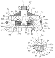
他方、バルブケース5の図4中下側であるリザーバ室側には、バルブV2が設けられている。バルブV2は、環板状であってバルブケース5に積まれるとともに外周弁座5hに離着座して環状窓5fを開閉可能であって環状窓5fに臨む孔30aを有する第一弁体30と、環板状であってバルブケース5の内周弁座5gと第一弁体30との間に介装されて孔30aを開閉可能な第二弁体31と、第一弁体30の反弁座部材側に重ねられて孔30aに通じる絞りとしてのオリフィス32aを有する絞り弁体としてのオリフィス弁体32と、第一弁体30を第二弁体31側へ向けて付勢する付勢部材B2とを備えている。
On the other hand, on the reservoir chamber side, which is the lower side of the
第一弁体30は、図4に示すように、前述の通り環板状であって、内周が固定端として外周側の撓みが許容され、外周弁座5hに離着座して減衰ポート5dを開閉するようになっており、バルブV2の主弁体として機能している。また、本実施の形態では、図3に示すように、第一弁体30は、環状窓5fに対向する位置に周方向に沿って配置される複数の孔30aを備える他、外周に切欠で形成される複数の固定オリフィス30bを備えている。したがって、第一弁体30は、外周弁座5hに着座した状態では、固定オリフィス30bを介して減衰ポート5dとリザーバ室Rとを連通させる。
As shown in FIG. 4, the
そして、第一弁体30のバルブケース側には、第二弁体31が配置されている。第二弁体31は、外径が外周弁座5hの内径よりも小径であって孔30aを開閉可能な径とされる環板状であって、内周弁座5gと第一弁体30との間に介装されている。また、第二弁体31は、内周が固定端として外周側の撓みが許容され、第一弁体30に離着して孔30aを開閉するようになっており、バルブV2の副弁体として機能している。
A
また、本実施の形態の第一弁体30の反バルブケース側には、図4に示すように、オリフィス弁体32が設けられている。オリフィス弁体32は、外径が第一弁体30の外径と同径の環板状であって、内周が固定端とされて第一弁体30と共に外周の撓みが許容されている。また、オリフィス弁体32は、図3に示すように、同一円周上に配置される四つの円弧状孔32bと、外周から開口してそれぞれ対応する円弧状孔32bに通じる四つのオリフィス32aとを備えている。
Further, as shown in FIG. 4, an
なお、本実施の形態では、第一弁体30とオリフィス弁体32との間には、図4に示すように、外径が第一弁体30の外径と同径の環板状のディスク33が介装されている。ディスク33は、図3に示すように、内周が固定端とされて第一弁体30およびオリフィス弁体32と共に外周の撓みが許容されており、第一弁体30の孔30aとオリフィス弁体32の円弧状孔32bと対向するC型の切欠33aを備えている。よって、孔30aとオリフィス32aは、切欠33aおよび円弧状孔32bを介して連通されており、孔30aはオリフィス32aに通じる通路として機能している。そして、第二弁体31が孔30aを開放すると圧側室R2とリザーバ室Rは、孔30a、切欠33a、円弧状孔32bおよびオリフィス32aを通じて連通される。このように、ディスク33は、切欠33aを孔30aと円弧状孔32bとに対向させて両者を連通する役割を果たしており、第一弁体30とオリフィス弁体32の周方向相対的な位置によらず孔30aと円弧状孔32bの連通度合を大きくするために設けられている。第一弁体30の孔30aとオリフィス弁体32の円弧状孔32bとの連通度合が或る程度確保できる場合、ディスク33は廃止してもよい。
In addition, in the present embodiment, between the
付勢部材B2は、第一弁体30の反バルブケース側に配置されており、オリフィス弁体32の反バルブケース側に積層されている。具体的には、付勢部材B2は、第一弁体30の反バルブケース側に配置される弾性を有する環状板34と、環板状であって第一弁体30と環状板34との間に介装されるリング35とを備えている。
The biasing member B2 is arranged on the side opposite to the valve case of the
環状板34は、複数枚が積層されて設けられており、内周が固定端とされて外周側の撓みが許容されている。リング35は、内径が第一弁体30と環状板34の内径よりも大径であるとともに第一弁体30と環状板34の外径よりも小径とされており、本実施の形態では、オリフィス弁体32の反バルブケース側に積層される環板状のリング保持環36に取り付けられている。リング保持環36は、図3に示すように、第一弁体30と同径とされ、内周が固定端とされて外周側の撓みが許容されており、リング35が外周に溶接或いは接着によって取り付けられている。また、リング保持環36の反バルブケース側には外径がリング35よりも小径であって、リング35よりも薄肉の環状板でなるスペーサ37が介装されている。スペーサ37もまた内周が固定端とされて外周側の撓みが許容されている。
The
さらに、付勢部材B2の環状板34の反バルブケース側には、環状であって環状板34の外径よりも外径が小径の間座38が重ねられている。そして、ケース側バルブ20、バルブケース5、第二弁体31、第一弁体30、ディスク33、オリフィス弁体32、リング35が取り付けられたリング保持環36、スペーサ37、三枚の環状板34および間座38がバルブケース5の内周に嵌合されるガイドロッド21の外周に順番に組み付けられるとともに、ガイドロッド21の先端に螺着されるナット22によってガイドロッド21に固定される。ケース側バルブ20、第二弁体31、第一弁体30、ディスク33、オリフィス弁体32、リング保持環36、スペーサ37および環状板34は、ナット22の螺着によって固定されると、内周が固定されて外周の撓みが許容された状態でガイドロッド21に固定される。
Further, a
リング35とスペーサ37とでは横方向から見て高さが異なっているので、環状板34の外周が下方へ撓んでおり、環状板34に初期撓みが与えられている。このように初期撓みが与えられるので、環状板34は、第一弁体30をバルブケース側へ押しつける付勢力を発揮して第一弁体30を外周弁座5hへ着座させている。
Since the
つまり、付勢部材B2は、本実施の形態では、環状板34の弾発力で第一弁体30を付勢している。そして、付勢部材B2は、この付勢力によって第一弁体30が減衰ポート5dを介して作用する圧側室R2の圧力を受けて外周弁座5hから離座する際の圧側室R2とリザーバ室Rの差圧である開弁圧を設定している。開弁圧は、環状板34の設置枚数によって調節でき、本実施の形態では、三枚の環状板34を設けているが要求される開弁圧によって設置枚数は適宜変更できる。
That is, the biasing member B2 biases the
そして、図4に示すように、バルブケース5を横方向から見て、内周弁座5gの方が外周弁座5hよりも高くなっているので、付勢部材B2からの付勢力を受けた第一弁体30は外周が図4中上方なる第二弁体31側へ撓んだ状態で外周弁座5hに着座する。このように第一弁体30が第二弁体31側へ撓むのに対して、第二弁体31も第一弁体30に倣って環状窓5f側へ向けて撓むので、第二弁体31が第一弁体30のバルブケース側面に密着して孔30aを閉塞する。このように、バルブV2をバルブケース5とともにガイドロッド21に固定した状態で何ら圧力も流体力も作用しない無負荷状態において、第二弁体31が第一弁体30のバルブケース側面に密着して孔30aを確実に閉塞する。なお、本実施の形態では、横方向から見て外周弁座5hより内周弁座5gを高くしているが、内周弁座5gが外周弁座5hに対して低くても、第二弁体31の反弁座部材側面となる図4中下面が弁座部材としてのバルブケース5の外周弁座5hよりも高くなっていればよい。このようにすれば、第一弁体30の内周の固定位置は、外周弁座5hよりも高くなって、付勢部材B2によって付勢されると図4中上方側となる外周弁座5h側へ撓んで第二弁体31に密着する。なお、第二弁体31と内周弁座5gとの間にスペーサを設けて、第二弁体31の反弁座部材側面となる図4中下面が弁座部材としてのバルブケース5の外周弁座5hよりも高くしてもよい。この場合も、第二弁体31は、第一弁体30が外周弁座5hに着座する状態では、第一弁体30とともに撓んで第一弁体30に密着して孔30aを閉塞できる。
Then, as shown in FIG. 4, when the
このように構成されたバルブV2は、圧側室R2の圧力がリザーバ室Rの圧力より高くなっても両者の差圧が前記開弁圧に達するまでは第一弁体30が外周弁座5hに着座した状態に維持される。この状態では固定オリフィス30bを通じて圧側室R2とリザーバ室Rとが連通されるので、圧側室R2内の作動油は固定オリフィス30bのみを通過してリザーバ室Rへ移動する。また、第二弁体31は、無負荷状態でも第一弁体30に密着しており、減衰ポート5dを介して圧側室R2の圧力を受けるので第一弁体30に密着したままとなりオリフィス32aに通じる孔30aを閉塞する。よって、オリフィス弁体32のオリフィス32aには、作動油は流れずオリフィス32aは機能しない。
In the valve V2 configured as described above, even if the pressure in the pressure side chamber R2 becomes higher than the pressure in the reservoir chamber R, the
そして、バルブV2は、圧側室R2の圧力がリザーバ室Rの圧力より高くなって両者の差圧が前記開弁圧に達すると、第一弁体30を押す力が環状板34の付勢力に打ち勝って第一弁体30が撓んで外周弁座5hから離座し開弁する。バルブV2が開弁すると減衰ポート5dが開放され、作動油は、第一弁体30と外周弁座5hとの間にできる環状隙間を介して圧側室R2からリザーバ室Rへ移動するようになる。なお、第二弁体31は、第一弁体30とともに圧側室R2の圧力を受けて撓むので第一弁体30のバルブケース側面に密着した状態となり孔30aを閉塞してオリフィス32aを機能させない。
Then, in the valve V2, when the pressure in the pressure side chamber R2 becomes higher than the pressure in the reservoir chamber R and the pressure difference between the two reaches the valve opening pressure, the force pushing the
また、バルブV2は、リザーバ室Rの圧力が圧側室R2の圧力より高いと背面側から作用するリザーバ室Rによって押しつけられて第一弁体30が外周弁座5hに密着し減衰ポート5dを閉塞する。また、オリフィス32a、円弧状孔32b、切欠33aおよび孔30aを介してリザーバ室Rの圧力が第二弁体31に作用して第二弁体31が環状窓5f側へ撓んで第一弁体30から離間して孔30aを開放する。よって、リザーバ室Rの圧力が圧側室R2の圧力より高くなると、前述の固定オリフィス30bを介してリザーバ室Rと圧側室R2とが連通されるほか、第二弁体31が孔30aを開放してオリフィス32aを介してもリザーバ室Rと圧側室R2とが連通される。
Further, when the pressure in the reservoir chamber R is higher than the pressure in the pressure side chamber R2, the valve V2 is pressed by the reservoir chamber R acting from the back side so that the
このようにバルブV2では、圧側室R2の圧力がリザーバ室Rの圧力よりも高いがその差圧が小さい場合には、作動油に固定オリフィス30bを通過させ、リザーバ室Rの圧力が圧側室R2の圧力よりも高いがその差圧が小さいと作動油に固定オリフィス30bおよびオリフィス32aを通過させる。そして、このように構成されたバルブV2では、無負荷状態で第二弁体31が第一弁体30に密着して孔30aを確実に閉塞できるので圧側室R2からリザーバ室Rへ作動油が向かう作動時において減衰特性が変化する不具合も解消され、オリフィス32aを確実に片効きのオリフィスとして機能させ得る。
As described above, in the valve V2, when the pressure in the pressure side chamber R2 is higher than the pressure in the reservoir chamber R but the differential pressure is small, the hydraulic oil is allowed to pass through the fixed
なお、第一弁体30における孔30aをオリフィスとして機能させてもよく、その場合には、オリフィス弁体32の代わりに、オリフィス弁体32と同様の円弧状孔と外周から開口して円弧状孔に連通する切欠とを備えた環板状のディスクを設けて、オリフィス弁体32を廃止してもよい。また、弁座部材としてのバルブケース5の形状および構造は、前述したところに限定されるものではなく、適宜設計変更することができる。
The
バルブV1,V2および緩衝器Dは、以上のように構成される。つづいて、緩衝器Dの作動について説明する。まず、緩衝器Dが伸長する場合について説明する。ピストン2がシリンダ1に対して図1中上方側へ移動して、緩衝器Dが伸長行程にある場合、伸側室R1が圧縮されて、圧側室R2が拡大される。ピストン2のシリンダ1に対する移動速度であるピストン速度が低速の場合、伸側室R1の圧力が圧側室R2の圧力より高くなるが、両者の差圧は第一弁体10の開弁圧に達しない。そのため、バルブV1における第一弁体10が外周弁座2eに着座した状態に維持され、作動油は、固定オリフィス10bを通じて伸側室R1から圧側室R2へ移動する。よって、伸長行程時であってピストン速度が低速域にある場合、緩衝器Dは、図5に示すように、固定オリフィス10bによって減衰力を発揮し、オリフィス特有のピストン速度の二乗に比例するような特性の減衰力を発揮する。
The valves V1 and V2 and the shock absorber D are configured as described above. Next, the operation of the shock absorber D will be described. First, the case where the shock absorber D expands will be described. When the
また、緩衝器Dの伸長行程時には、ピストンロッド3がシリンダ1内から退出するので、このピストンロッド3がシリンダ1から退出する体積分の作動油がシリンダ1内で不足する。ピストン速度が低速の場合、リザーバ室Rと圧側室R2の差圧が小さいためバルブケース5に設けたケース側バルブ20は開弁しないものの、バルブV2の第二弁体31が撓んで孔30aを開放する。よって、シリンダ1内で不足する体積分の作動油は、固定オリフィス30bおよびオリフィス32aを介してリザーバ室Rからシリンダ1内へ供給される。つまり、低いピストン速度で緩衝器Dが伸長する場合、固定オリフィス30bのみならずオリフィス32aも有効となる。
Further, during the extension stroke of the shock absorber D, the
伸長行程の際のピストン速度が高速となると、伸側室R1と圧側室R2の差圧が大きくなり、両者の差圧が第一弁体10の開弁圧に達すると、第一弁体10を推す力が付勢部材B1の付勢力に打ち勝って第一弁体10が撓んで外周弁座2eから離座して伸側ポート2aを開放する。すると、作動油は、第一弁体10と外周弁座2eとの間に出現する環状隙間を通過して伸側室R1から圧側室R2へ移動する。また、リザーバ室Rと圧側室R2の差圧が大きくなるので、バルブケース5に設けたケース側バルブ20が開弁して吸込ポート5eを開放する。よって、シリンダ1内で不足する分の作動油は、吸込ポート5eを通過してリザーバ室Rからシリンダ1内に供給されるようになる。よって、伸長行程時であってピストン速度が高速域にある場合、緩衝器Dは、図5に示すように、第一弁体10と付勢部材B1によって減衰力を発揮し、ピストン速度に比例するような特性の減衰力を発揮する。
When the piston speed during the extension stroke becomes high, the differential pressure between the expansion side chamber R1 and the compression side chamber R2 increases, and when the differential pressure between the two reaches the valve opening pressure of the
また、伸長行程時において、ピストン速度が低速域にある場合にはリザーバ室Rから圧側室R2へ向かう作動油は、固定オリフィス30bとオリフィス32aの双方を通過できるので、第二弁体31の開弁によって流路面積を大きく確保できる。ピストン速度が高速域に達すると、ケース側バルブ20が開弁して吸込ポート3eを開放するが、ケース側バルブ20の開弁前後で流路面積の変化度合を小さくできるので、圧側室R2内の圧力変動を抑制できる。
Further, during the extension stroke, when the piston speed is in the low speed range, the hydraulic oil flowing from the reservoir chamber R to the pressure side chamber R2 can pass through both the fixed
つづいて、緩衝器Dが収縮する場合について説明する。ピストン2がシリンダ1に対して図1中下方側へ移動して、緩衝器Dが収縮行程にある場合、圧側室R2が圧縮されて、伸側室R1が拡大される。ピストン速度が低速の場合、圧側室R2の圧力が伸側室R1の圧力より高くなるが両者の差圧は小さく、ピストン側バルブ6は開弁しないが、バルブV1の第二弁体11が撓んで孔10aを開放する。よって、圧側室R2から伸側室R1へ向かう作動油は、固定オリフィス10bおよびオリフィス12aを介して移動する。つまり、低いピストン速度で緩衝器Dが収縮する場合、固定オリフィス10bのみならずオリフィス12aも有効となる。
Next, a case where the shock absorber D contracts will be described. When the
また、緩衝器Dの収縮行程時には、ピストンロッド3がシリンダ1内へ侵入するので、このピストンロッド3がシリンダ1へ侵入する体積分の作動油がシリンダ1内で過剰となる。ピストン速度が低速の場合、圧側室R2とリザーバ室Rと差圧が小さいためバルブV2における第一弁体30は開弁しないので、作動油は、固定オリフィス30bを介して圧側室R2からリザーバ室Rへ移動する。よって、収縮行程時であってピストン速度が低速域にある場合、緩衝器Dは、図5に示すように、固定オリフィス30bによって減衰力を発揮し、オリフィス特有のピストン速度の二乗に比例するような特性の減衰力を発揮する。
Further, since the
収縮行程の際のピストン速度が高速となると、圧側室R2とリザーバ室Rの差圧が大きくなり、両者の差圧が第一弁体30の開弁圧に達すると、第一弁体30を推す力が付勢部材B2の付勢力に打ち勝って第一弁体30が撓んで外周弁座5hから離座して減衰ポート5dを開放する。すると、作動油は、第一弁体30と外周弁座5hとの間に出現する環状隙間を通過して圧側室R2からリザーバ室Rへ移動する。また、圧側室R2と伸側室R1の差圧が大きくなるので、ピストン2に設けたピストン側バルブ6が開弁して圧側ポート2bを開放する。よって、収縮行程時であってピストン速度が高速域にある場合、緩衝器Dは、図5に示すように、第一弁体30と付勢部材B2によって減衰力を発揮し、ピストン速度に比例するような特性の減衰力を発揮する。
When the piston speed during the contraction stroke becomes high, the pressure difference between the pressure side chamber R2 and the reservoir chamber R increases, and when the pressure difference between the two reaches the valve opening pressure of the
また、収縮行程時において、ピストン速度が低速域にある場合には圧側室R2から伸側室R1へ向かう作動油は、固定オリフィス10bとオリフィス12aの双方を通過できるので、第二弁体11の開弁によって流路面積を大きく確保できる。ピストン速度が高速域に達すると、ピストン側バルブ6が開弁して圧側ポート2bを開放するが、ピストン側バルブ6の開弁前後で流路面積の変化度合を小さくできるので、伸側室R1内の圧力変動を抑制できる。
Further, during the contraction stroke, when the piston speed is in the low speed range, the hydraulic oil flowing from the pressure side chamber R2 to the expansion side chamber R1 can pass through both the fixed
以上のように緩衝器Dは、シリンダ1と、シリンダ1内に移動自在に挿入されるとともにシリンダ1内を伸側室R1と圧側室R2とに区画するピストン2と、シリンダ1内に挿入されてピストン2に連結されるピストンロッド3と、シリンダ1を覆ってシリンダ1との間にリザーバ室Rを形成する外筒4と、シリンダ1の端部に設けられて圧側室R2とリザーバ室Rとを仕切るバルブケース5と、ピストン2の伸側室R1側に設けられてピストン2に設けられる圧側ポート2bを開閉するピストン側バルブ6と、バルブケース5の圧側室R2側に設けられてバルブケース5に設けられる吸込ポート5eを開閉するケース側バルブ20と、ピストン2の圧側室R2側に配置されるバルブV1と、バルブケース5のリザーバ室R側に配置されるバルブV2とを備えている。
As described above, the shock absorber D is inserted into the
このように構成された緩衝器Dでは、伸長行程時におけるケース側バルブ20の開弁の前後で圧側室R2の圧力変動を抑制でき、収縮行程時におけるピストン側バルブ6の開弁の前後で伸側室R1の圧力変動を抑制できる。よって、このように構成された緩衝器Dによれば、無負荷状態でも絞りとしてのオリフィス12a,32aを確実に閉鎖でき、異音の発生を抑制できるとともに、車両のサスペンションに利用すると車両における乗り心地を向上できる。
In the shock absorber D configured as described above, the pressure fluctuation of the pressure side chamber R2 can be suppressed before and after the opening of the
また、ピストン2の圧側室R2側にバルブV1を設けてバルブケース5にはバルブV2の代わりにリーフバルブを設ける場合、緩衝器Dの収縮行程時において、ピストン側バルブ6の開弁の前後で伸側室R1の圧力変動を抑制でき、異音の発生を防止できる。緩衝器Dの伸長行程時において異音発生の問題がないようであればこのようにピストン2の圧側室R2側にのみバルブV1を設けるようにしてもよい。さらに、バルブケース5のリザーバ室R側にバルブV2を設けてピストン2にはバルブV1の代わりにリーフバルブを設ける場合、緩衝器Dの伸長行程時において、ケース側バルブ20の開弁の前後で圧側室R2の圧力変動を抑制でき、異音の発生を防止できる。緩衝器Dの収縮行程時において異音発生の問題がないようであればこのようにバルブケース5のリザーバ室R側にのみバルブV2を設けるようにしてもよい。
When a valve V1 is provided on the pressure side chamber R2 side of the
そして、本発明のバルブV1,V2は、ポート(伸側ポート2a、減衰ポート5d)と、ポート(伸側ポート2a、減衰ポート5d)の出口端に連通される環状窓2c,5fと、環状窓2c,5fの内周側に設けられた内周弁座2d,5gと、環状窓2c,5fの外周弁座2e,5hとを有する弁座部材2,5と、環板状であって弁座部材2,5に積まれるとともに外周弁座2e,5hに離着座して環状窓2c,5fを開閉可能であって環状窓2c,5fに臨んでオリフィス(絞り)或いはオリフィス(絞り)12aに通じる通路となる孔10a,30aを有する第一弁体10,30と、環板状であって弁座部材2,5の内周弁座2d,5gと第一弁体10,30との間に介装されて孔10a,30aを開閉可能な第二弁体11,31と、第一弁体10,30を第二弁体11,31側へ向けて付勢する付勢部材B1,B2とを備え、弁座部材2,5の軸方向に直交する方向から見て第二弁体11,31の反弁座部材側面を弁座部材の外周弁座よりも高くしている。
The valves V1 and V2 of the present invention include ports (
このように構成されたバルブV1,V2では、無負荷状態で第二弁体11,31が第一弁体10,30に密着して孔10a,30aを閉塞できる。よって、本発明のバルブV1,V2によれば、無負荷状態でも孔を確実に閉鎖でき、減衰特性が変化する不具合が解消され、オリフィス(絞り)12a,32aを確実に片効きのオリフィス(絞り)として機能させ得る。
In the valves V1 and V2 configured as described above, the
また、このように構成されたバルブV1,V2を緩衝器Dに適用すれば、オリフィス(絞り)12a,32aを緩衝器Dの伸長行程時にのみ或いは収縮行程時にのみ機能する片効きのオリフィス(絞り)に設定できるので、緩衝器Dの伸縮行程時の減衰力特性と収縮行程時の減衰力特性を独立して設定できる。 Further, if the valves V1 and V2 configured as described above are applied to the shock absorber D, the orifices (throttles) 12a and 32a function as the one-way orifices (throttles) that function only during the expansion stroke or the contraction stroke of the shock absorber D. ), the damping force characteristic of the shock absorber D during the expansion/contraction stroke and the damping force characteristic of the shock absorber D during the contraction stroke can be set independently.
さらに、本実施の形態のバルブV1,V2における付勢部材B1,B2は、第一弁体10,30の反弁座部材側に配置される弾性を有する環状板14,34と、環板状であって第一弁体10,30と環状板14,34との間に介装され内径が第一弁体10,30と環状板14,34の内径よりも大径であるとともに第一弁体10,30と環状板14,34の外径よりも小径なリング15,35とを有している。このように構成されたバルブV1,V2は、付勢部材B1,B2の構造が簡素で軸方向長さも短くて済むので、緩衝器Dに適用しても緩衝器Dのストローク長を損なわないので、緩衝器Dの全長の長尺化も回避できる。
Further, the biasing members B1 and B2 in the valves V1 and V2 of the present embodiment include
なお、付勢部材B1は、図6に示すように、弾性体40で構成されてもよく、図示したところでは、オリフィス弁体12の円弧状孔12bがオリフィス12aを介さずに圧側室R2に連通してしまわないようにオリフィス弁体12と同径のディスク41を重ねて、弾性体40をピストンロッド3の先端に固定したストッパ42とディスク41との間に圧縮状態で介装すればよい。弾性体40は、たとえば、コイルばね、皿ばね等のばねやゴム等とされればよい。また、この構成を採用する場合、第二弁体11、第一弁体10、ディスク13、オリフィス弁体12およびディスク41がピストンロッド3に対して軸方向移動可能としておき、弾性体40の収縮によってこれらが一体となって弁座部材としてのピストン2から離間する構造も採用できる。図6に示したバルブV1における付勢部材B1の構成は、バルブケース5に設けられたバルブV2にも適用可能である。
The urging member B1 may be formed of an
また、本実施の形態のバルブV1,V2では、環板状であって第一弁体10,30の反弁座部材側に重ねられて孔10a,30aに通じるオリフィス(絞り)12a,32aを有するオリフィス弁体(絞り弁体)12,32を備えている。このように構成されたバルブV1,V2によれば、オリフィス弁体(絞り弁体)12,32を備えているので、第一弁体10,30とオリフィス弁体12,32の周方向の相対位置によらず、オリフィス(絞り)12a,32aの開口面積を一定とできる。孔10a,30aをオリフィス(絞り)として利用してもよいが、孔10a,30aと孔10a,30aを圧側室R2或いはリザーバ室Rへ連通するための切欠13a,33aとの連通度合は、第一弁体10,30とディスク13,33との周方向での相対位置により変化する。そのため、孔10a,30aをオリフィス(絞り)とする場合には、第一弁体10,30とディスク13,33の組立の際に周方向での位置決めが必須となるが、オリフィス弁体(絞り弁体)12,32を設けるとオリフィス(絞り)12a,32aの開口面積は変化しないので、組立作業が容易となり、常に一定の開口面積のオリフィス(絞り)12a,32aで減衰力発揮できる。
In addition, in the valves V1 and V2 of the present embodiment, the orifices (throttles) 12a and 32a that are annular plate-shaped and are superposed on the side opposite to the valve seat member of the
なお、前述した実施形態では、絞りをオリフィスとしているが、絞りは、オリフィス以外にもチョークとされてもよい。この場合、オリフィス12a,32aに代えてチョークを備えた絞り弁体をオリフィス弁体12,32の代わりに設ければよい。
In the above-described embodiment, the diaphragm is an orifice, but the diaphragm may be a choke other than the orifice. In this case, a throttle valve body having a choke may be provided instead of the
また、本実施の形態のバルブV1,V2では、固定オリフィス10b,30bが設けられているので、バルブV1,V2のみで緩衝器Dの伸縮両側の減衰力特性を独立に設定可能である。なお、本実施の形態では、固定オリフィス10b,30bを第一弁体10,30の外周に設けた切欠によって設置されているが、外周弁座2e,5hに環状窓2c,5fを圧側室R2或いはリザーバ室Rに連通する凹部を設けて、この凹部を固定オリフィスとしてもよい。
Further, since the valves V1 and V2 of the present embodiment are provided with the fixed
なお、本実施の形態では、ピストン2の圧側室R2側にバルブV1を設けているが、ピストン2の伸側室R1側にバルブV1を設けてもよいし、バルブケース5のリザーバ室R側にバルブV2を設けているが、バルブケース5の圧側室R2側にバルブV2を設けてもよい。緩衝器の構造によらず、バルブV1,V2は、無負荷状態でもオリフィスを確実に閉鎖でき、減衰特性が変化する不具合を解消できるという利点は失われない。
Although the valve V1 is provided on the pressure side chamber R2 side of the
また、バルブV1,V2は、図7に示すように、減衰力を可変にできるユニフロー型の緩衝器D1への適用も可能である。この緩衝器D1は、緩衝器Dの構成に加えて、シリンダ1と外筒4との間に中間筒50を備えており、シリンダ1に設けた孔1aを介してシリンダ1と中間筒50との間の環状隙間が伸側室R1に連通されている。さらに、緩衝器D1は、外筒4の下方の側部に可変減衰バルブVVを備えたバルブブロックVBを備えている。バルブブロックVBは、中間筒50と外筒4との間の環状隙間で形成されるリザーバ室Rと前記環状隙間とを可変減衰バルブVVを介して連通している。よって、この緩衝器D1では、シリンダ1と中間筒50との間の環状隙間とこの環状隙間をリザーバ室Rへ連通するバルブブロックVB内に設けられる通路52とで減衰通路Pを構成している。
Further, as shown in FIG. 7, the valves V1 and V2 can be applied to a uniflow type shock absorber D1 that can vary the damping force. In addition to the structure of the shock absorber D, the shock absorber D1 includes an
可変減衰バルブVVは、通路52に設けられており、伸側室R1からリザーバ室Rへ向かう作動油の流れのみを許容するとともに減衰通路Pを通過する作動油の流れに抵抗を与える。
The variable damping valve VV is provided in the
可変減衰バルブVVは、ソレノイドを備えた電磁弁とされており、伸側室R1からリザーバ室Rへ向かって減衰通路Pを流れる作動油に抵抗を与えられるとともに、ソレノイドへ与える電流によって開弁圧を調節できるようになっている。このように構成される可変減衰バルブVVは、ソレノイドへの通電量に応じて開弁圧を調整する圧力制御弁として機能し、緩衝器が発生する減衰力を調節できる。なお、可変減衰バルブVVは、開弁圧の調整によって減衰力を可変にする減衰バルブ以外にも減衰力の調整が可能であれば任意構成の減衰バルブを利用できる。 The variable damping valve VV is an electromagnetic valve provided with a solenoid, and is capable of imparting resistance to the working oil flowing through the damping passage P from the expansion side chamber R1 to the reservoir chamber R, and at the same time opening the valve opening pressure by the current applied to the solenoid. It can be adjusted. The variable damping valve VV configured as described above functions as a pressure control valve that adjusts the valve opening pressure according to the amount of electricity supplied to the solenoid, and can adjust the damping force generated by the shock absorber. As the variable damping valve VV, a damping valve having an arbitrary configuration can be used as long as the damping force can be adjusted in addition to the damping valve that makes the damping force variable by adjusting the valve opening pressure.
つづいて、このように構成された緩衝器D1の作動について説明する。まず、緩衝器D1が伸長する場合について説明する。ピストン2がシリンダ1に対して図7中上方側へ移動して、緩衝器D1が伸長行程にある場合、伸側室R1が圧縮されて、圧側室R2が拡大される。ピストン2のシリンダ1に対する移動速度であるピストン速度が低速の場合、伸側室R1の圧力が圧側室R2の圧力より高くなるが、両者の差圧は第一弁体10の開弁圧に達しない。そのため、バルブV1における第一弁体10が外周弁座2eに着座した状態に維持される。可変減衰バルブVVの開弁圧を低くすれば、可変減衰バルブVVが開弁して伸側室R1から減衰通路Pを通じてリザーバ室Rへ作動油が移動する。また、可変減衰バルブVVの開弁圧を高くすれば、可変減衰バルブVVが閉弁したままとなるので、作動油は、固定オリフィス10bを通じて伸側室R1から圧側室R2へ移動する。
Next, the operation of the shock absorber D1 thus configured will be described. First, the case where the shock absorber D1 expands will be described. When the
よって、伸長行程時であってピストン速度が低速域にある場合、緩衝器Dは、図8に示すように、可変減衰バルブVVの調整により、可変減衰バルブVVの開弁圧を最小する際の減衰力(図8中一点鎖線)から固定オリフィス10bのみによって発生される減衰力(図8中実線)までの範囲で減衰力を調整できる。
Therefore, when the piston speed is in the low speed range during the extension stroke, the shock absorber D adjusts the variable damping valve VV to minimize the valve opening pressure of the variable damping valve VV as shown in FIG. The damping force can be adjusted within the range from the damping force (one-dot chain line in FIG. 8) to the damping force generated by only the fixed
また、緩衝器D1の伸長行程時には、ピストンロッド3がシリンダ1内から退出するので、このピストンロッド3がシリンダ1から退出する体積分の作動油がシリンダ1内で不足する。ピストン速度が低速の場合、リザーバ室Rと圧側室R2の差圧が小さいためバルブケース5に設けたケース側バルブ20は開弁しないが、バルブV2の第二弁体31が撓んで孔30aを開放する。よって、シリンダ1内で不足する体積分の作動油は、固定オリフィス30bおよびオリフィス32aを介してリザーバ室Rからシリンダ1内へ供給される。つまり、低いピストン速度で緩衝器Dが伸長する場合、固定オリフィス30bのみならずオリフィス32aも有効となる。
Further, during the expansion stroke of the shock absorber D1, the
伸長行程の際のピストン速度が高速となると、伸側室R1と圧側室R2の差圧が大きくなる。伸側室R1と圧側室R2の差圧が第一弁体10の開弁圧に達するまでは、可変減衰バルブVVの開弁圧の調整によって伸側室R1内の圧力を制御できる。伸側室R1と圧側室R2の差圧が第一弁体10の開弁圧に達すると、第一弁体10を推す力が付勢部材B1の付勢力に打ち勝って第一弁体10が撓んで外周弁座2eから離座して伸側ポート2aを開放する。すると、作動油は、第一弁体10と外周弁座2eとの間に出現する環状隙間を通過して伸側室R1から圧側室R2へ移動するようになる。また、リザーバ室Rと圧側室R2の差圧が大きくなるので、バルブケース5に設けたケース側バルブ20が開弁して吸込ポート5eを開放する。よって、シリンダ1内で不足する分の作動油は、吸込ポート5eを通過してリザーバ室Rからシリンダ1内に供給されるようになる。
When the piston speed during the extension stroke becomes high, the differential pressure between the extension side chamber R1 and the compression side chamber R2 becomes large. Until the differential pressure between the expansion side chamber R1 and the compression side chamber R2 reaches the valve opening pressure of the
よって、伸長行程時であってピストン速度が高速域にある場合、緩衝器D1は、図7に示すように、可変減衰バルブVVの調整により、可変減衰バルブVVの開弁圧を最小する際の減衰力(図8中一点鎖線)から第一弁体10によって発生される減衰力(図8中実線)までの範囲で減衰力を調整できる。このように緩衝器D1に適用されたバルブV1における第一弁体10は、伸長行程時の最大減衰力を決するリリーフバルブとして機能する。
Therefore, when the piston speed is in the high speed range during the extension stroke, the shock absorber D1 adjusts the variable damping valve VV to minimize the opening pressure of the variable damping valve VV as shown in FIG. The damping force can be adjusted within a range from the damping force (dotted line in FIG. 8) to the damping force generated by the first valve body 10 (solid line in FIG. 8). In this way, the
また、伸長行程時において、ピストン速度が低速域にある場合にはリザーバ室Rから圧側室R2へ向かう作動油は、固定オリフィス30bとオリフィス32aの双方を通過できるので、第二弁体31の開弁によって流路面積を大きく確保できる。ピストン速度が高速域に達すると、ケース側バルブ20が開弁して吸込ポート3eを開放するが、ケース側バルブ20の開弁前後で流路面積の変化度合を小さくできるので、圧側室R2内の圧力変動を抑制できる。
Further, during the extension stroke, when the piston speed is in the low speed range, the hydraulic oil flowing from the reservoir chamber R to the pressure side chamber R2 can pass through both the fixed
つづいて、緩衝器D1が収縮する場合について説明する。ピストン2がシリンダ1に対して図1中下方側へ移動して、緩衝器D1が収縮行程にある場合、圧側室R2が圧縮されて、伸側室R1が拡大される。ピストン速度が低速の場合、圧側室R2の圧力が伸側室R1の圧力より高くなる。圧側室R2と伸側室R1の差圧は小さいためピストン側バルブ6は開弁しないが、バルブV1の第二弁体11が撓んで孔10aを開放する。よって、圧側室R2から伸側室R1へ向かう作動油は、固定オリフィス10bおよびオリフィス12aを介して移動する。つまり、低いピストン速度で緩衝器D1が収縮する場合、固定オリフィス10bのみならずオリフィス12aも有効となる。
Next, a case where the shock absorber D1 contracts will be described. When the
また、緩衝器Dの収縮行程時には、ピストンロッド3がシリンダ1内へ侵入するので、このピストンロッド3がシリンダ1へ侵入する体積分の作動油がシリンダ1内で過剰となる。ピストン速度が低速の場合、圧側室R2とリザーバ室Rと差圧が小さいためバルブV2における第一弁体30は開弁しない。可変減衰バルブVVの開弁圧を低くすれば、可変減衰バルブVVが開弁して伸側室R1から減衰通路Pを通じてリザーバ室Rへ作動油が移動する。また、可変減衰バルブVVの開弁圧を高くすれば、可変減衰バルブVVが閉弁したままとなるので、作動油は、固定オリフィス30bを通じて圧側室R2からリザーバ室Rへ移動する。
Further, since the
よって、収縮行程時であってピストン速度が低速域にある場合、緩衝器D1は、図7に示すように、可変減衰バルブVVの調整により、可変減衰バルブVVの開弁圧を最小する際の減衰力(図8中一点鎖線)から固定オリフィス30bのみによって発生される減衰力(図8中実線)までの範囲で減衰力を調整できる。
Therefore, when the piston speed is in the low speed range during the contraction stroke, the shock absorber D1 adjusts the variable damping valve VV to minimize the opening pressure of the variable damping valve VV as shown in FIG. The damping force can be adjusted within a range from the damping force (one-dot chain line in FIG. 8) to the damping force generated by only the fixed
収縮行程の際のピストン速度が高速となると、圧側室R2とリザーバ室Rの差圧が大きくなる。この状況となると圧側室R2と伸側室R1の差圧が大きくなるので、ピストン2に設けたピストン側バルブ6が開弁して圧側ポート2bを開放するので、圧側室R2と伸側室R1の差圧がピストン側バルブ6の開弁圧に程度に維持される。そして、圧側室R2とリザーバ室Rの差圧が第一弁体30の開弁圧に達するまでは、可変減衰バルブVVの開弁圧の調整によってシリンダ1内の圧力を制御できる。また、圧側室R2とリザーバ室Rの差圧が第一弁体30の開弁圧に達すると、第一弁体30を推す力が付勢部材B2の付勢力に打ち勝って第一弁体30が撓んで外周弁座5hから離座して減衰ポート5dを開放する。すると、作動油は、第一弁体30と外周弁座5hとの間に出現する環状隙間を通過して圧側室R2からリザーバ室Rへ移動するようになる。
When the piston speed during the contraction stroke becomes high, the differential pressure between the pressure side chamber R2 and the reservoir chamber R becomes large. In this situation, the pressure difference between the compression side chamber R2 and the expansion side chamber R1 becomes large, so the
よって、収縮行程時であってピストン速度が高速域にある場合、緩衝器D1は、図7に示すように、可変減衰バルブVVの調整により、可変減衰バルブVVの開弁圧を最小する際の減衰力(図8中一点鎖線)から第一弁体30によって発生される減衰力(図8中実線)までの範囲で減衰力を調整できる。このように緩衝器D1に適用されたバルブV2における第一弁体30は、収縮行程時の最大減衰力を決するリリーフバルブとして機能する。
Therefore, when the piston speed is in the high speed range during the contraction stroke, the shock absorber D1 adjusts the variable damping valve VV to minimize the opening pressure of the variable damping valve VV as shown in FIG. The damping force can be adjusted within a range from the damping force (dotted line in FIG. 8) to the damping force generated by the first valve body 30 (solid line in FIG. 8). In this way, the
また、収縮行程時において、ピストン速度が低速域にある場合には圧側室R2から伸側室R1へ向かう作動油は、固定オリフィス10bとオリフィス12aの双方を通過できるので、第二弁体11の開弁によって流路面積を大きく確保できる。ピストン速度が高速域に達すると、ピストン側バルブ6が開弁して圧側ポート2bを開放するが、ピストン側バルブ6の開弁前後で流路面積の変化度合を小さくできるので、伸側室R1内の圧力変動を抑制できる。
Further, during the contraction stroke, when the piston speed is in the low speed range, the hydraulic oil flowing from the pressure side chamber R2 to the expansion side chamber R1 can pass through both the fixed
前述したところから理解できるように、緩衝器D1は、基本的には、伸長しても収縮してもシリンダ1内から作動油が可変減衰バルブVVを通じてリザーバ室Rへ流れるユニフロー型の緩衝器として振る舞う。また、伸側室R1内の圧力が過剰となると第一弁体10がリリーフバルブとして機能し,圧側室R2内の圧力が過剰となると第一弁体30がリリーフバルブとして機能するようになっている。
As can be understood from the above description, the shock absorber D1 is basically a uniflow type shock absorber in which hydraulic oil flows from the inside of the
以上のように緩衝器D1は、シリンダ1と、シリンダ1内に移動自在に挿入されるとともにシリンダ1内を伸側室R1と圧側室R2とに区画するピストン2と、シリンダ1内に挿入されてピストン2に連結されるピストンロッド3と、シリンダ1の外周に配置されて内方にリザーバ室Rが形成される外筒4と、シリンダ1の端部に設けられて圧側室R2とリザーバ室Rとを仕切るバルブケース5と、ピストン2の伸側室R1側に設けられてピストン2に設けられる圧側ポート2bを開閉するピストン側バルブ6と、バルブケース5の圧側室R2側に設けられてバルブケース5に設けられる吸込ポート5eを開閉するケース側バルブ20と、伸側室R1とリザーバ室Rとを連通する減衰通路Pと、減衰通路Pに設けられて伸側室R1からリザーバ室Rへ向かう流体の流れに抵抗を与える可変減衰バルブVVと、ピストン2の圧側室R2側に配置されるバルブV1と、バルブケース5のリザーバ室R側に配置されるバルブV2とを備えている。
As described above, the shock absorber D1 is inserted into the
このように構成された緩衝器D1では、伸長行程時におけるケース側バルブ20の開弁の前後で圧側室R2の圧力変動を抑制でき、収縮行程時におけるピストン側バルブ6の開弁の前後で伸側室R1の圧力変動を抑制できる。よって、このように構成された緩衝器D1によれば、無負荷状態でもオリフィス12a,32aを確実に閉鎖でき、異音の発生を抑制できるとともに、車両のサスペンションに利用すると車両における乗り心地を向上できる。
In the shock absorber D1 configured as described above, it is possible to suppress the pressure fluctuation of the pressure side chamber R2 before and after the opening of the
また、伸長行程の際にピストン速度が低速域にある場合、可変減衰バルブVVによって調整可能な減衰力幅は、前述したとおり、可変減衰バルブVVの開弁圧を最小する際の減衰力から固定オリフィス10bのみによって発生される減衰力までの範囲となる。よって、伸長行程の際の減衰力可変幅を大きくしたい場合は、固定オリフィス10bの流路面積を小さくして発生減衰力が大きくすればよい。このように固定オリフィス10bの流路面積を小さくして減衰力可変幅を大きくしても、収縮行程の際には、第二弁体11が孔10aを開放してオリフィス12aを有効とするので、収縮行程時における異音の発生が抑制される。
When the piston speed is in the low speed range during the extension stroke, the damping force width that can be adjusted by the variable damping valve VV is fixed from the damping force when the valve opening pressure of the variable damping valve VV is minimized, as described above. The range is up to the damping force generated only by the
さらに、収縮行程の際にピストン速度が低速域にある場合、可変減衰バルブVVによって調整可能な減衰力幅は、前述したとおり、可変減衰バルブVVの開弁圧を最小する際の減衰力から固定オリフィス30bのみによって発生される減衰力までの範囲となる。よって、収縮行程の際の減衰力可変幅を大きくしたい場合は、固定オリフィス30bの流路面積を小さくして発生減衰力が大きくすればよい。このように固定オリフィス30bの流路面積を小さくして減衰力可変幅を大きくしても、伸長行程の際には、第二弁体31が孔30aを開放してオリフィス32aを有効とするので、伸長行程時における異音の発生が抑制される。
Further, when the piston speed is in the low speed range during the contraction stroke, the damping force width that can be adjusted by the variable damping valve VV is fixed from the damping force when the valve opening pressure of the variable damping valve VV is minimized, as described above. The range is up to the damping force generated only by the
このように、緩衝器D1のピストン2の圧側室R2側にバルブV1を設けて、バルブケース5のリザーバ室R側にバルブV2を設けると、緩衝器D1の減衰力調整幅を大きくしつつも異音発生を抑制できるようになる。
As described above, when the valve V1 is provided on the pressure side chamber R2 side of the
また、ピストン2の圧側室R2側にバルブV1を設けてバルブケース5にはバルブV2の代わりにリーフバルブを設ける場合、緩衝器D1の伸長行程時における減衰力可変幅を大きくしつつ、収縮行程時においてピストン側バルブ6の開弁の前後で伸側室R1の圧力変動を抑制でき、異音の発生を防止できる。緩衝器D1の伸長行程時において異音発生の問題がないようであればこのようにピストン2の圧側室R2側にのみバルブV1を設けるようにしてもよい。
Further, when the valve V1 is provided on the pressure side chamber R2 side of the
さらに、バルブケース5のリザーバ室R側にバルブV2を設けてピストン2にはバルブV1の代わりにリーフバルブ或いは可変減衰バルブを設ける場合、緩衝器Dの収縮行程時における減衰力可変幅を大きくしつつ、伸長行程時において、ケース側バルブ20の開弁の前後で圧側室R2の圧力変動を抑制でき、異音の発生を防止できる。緩衝器Dの収縮行程時において異音発生の問題がないようであればこのようにバルブケース5のリザーバ室R側にのみバルブV2を設けるようにしてもよい。
Further, when a valve V2 is provided on the reservoir chamber R side of the
なお、前述したところでは、複筒型の緩衝器を例に本発明を説明したが、バルブV1は、単筒型緩衝器のピストンに適用してもよく、この場合、バルブV1をピストンの伸側室側と圧側室の一方または両方に設けてもよい。 In the above description, the present invention has been described by taking a double-cylinder type shock absorber as an example, but the valve V1 may be applied to a piston of a single-cylinder type shock absorber, and in this case, the valve V1 is extended by the piston. It may be provided in one or both of the side chamber side and the pressure side chamber.
以上、本発明の好ましい実施の形態を詳細に説明したが、特許請求の範囲から逸脱しない限り、改造、変形、および変更が可能である。 The preferred embodiments of the present invention have been described above in detail, but modifications, variations, and changes can be made without departing from the scope of the claims.
1・・・シリンダ、2・・・ピストン(弁座部材)、2a・・・伸側ポート(ポート)、2c,5f・・・環状窓、2d,5f・・・内周弁座、2e,5g・・・外周弁座、3・・・ピストンロッド、4・・・外筒、5・・・バルブケース(弁座部材)、5d・・・減衰ポート(ポート)、6・・・ピストン側バルブ、10,30・・・第一弁体、10a,30a・・・孔、10b,30b・・・固定オリフィス、11,31・・・第二弁体、12,32・・・オリフィス弁体(絞り弁体)、12a,32a・・・オリフィス(絞り)、14,34・・・環状板、15,35・・・リング、20・・・ケース側バルブ、40・・・弾性体、B1,B2・・・付勢部材、P・・・減衰通路、R・・・リザーバ室R・・・伸側室、R2・・・圧側室、V1,V2・・・バルブ、VV・・・可変減衰バルブ
DESCRIPTION OF
Claims (10)
環板状であって弁座部材に積まれるとともに前記外周弁座に離着座して前記環状窓を開閉可能であって前記環状窓に臨んで絞り或いは絞りに通じる通路となる孔を有する第一弁体と、
環板状であって前記弁座部材の内周弁座と前記第一弁体との間に介装されて前記孔を開閉可能な第二弁体と、
前記第一弁体を前記第二弁体側へ向けて付勢する付勢部材とを備え、
前記弁座部材の軸方向に直交する方向から見て前記第二弁体の反弁座部材側面を前記弁座部材の前記外周弁座よりも高く、
前記第一弁体は、前記付勢部材の付勢力を受けて前記外周弁座に着座する
ことを特徴とするバルブ。 And the port, and an annular window in communication with the outlet end of the port, a valve seat having an inner peripheral valve seat provided on the inner peripheral side of the annular window, and an outer peripheral valve seat provided on an outer peripheral side of the annular window Members,
A first annular plate-shaped member that is stacked on a valve seat member and that is seated on and off the outer peripheral valve seat to open and close the annular window and that faces the annular window and serves as a throttle or a passage leading to the throttle. Valve body,
A second valve body having an annular plate shape, which is interposed between the inner peripheral valve seat of the valve seat member and the first valve body and is capable of opening and closing the hole;
A biasing member that biases the first valve body toward the second valve body side,
When viewed from a direction orthogonal to the axial direction of the valve seat member, the side opposite the valve seat member of the second valve body is higher than the outer peripheral valve seat of the valve seat member ,
The first valve element is seated on the outer peripheral valve seat by receiving a biasing force of the biasing member .
前記第一弁体の反弁座部材側に配置される弾性を有する環状板と、
環板状であって前記第一弁体と前記環状板との間に介装され、内径が前記第一弁体と前記環状板の内径よりも大径であるとともに前記第一弁体と前記環状板の外径よりも小径なリングとを有する
ことを特徴とする請求項1に記載のバルブ。 The biasing member is
An annular plate having elasticity arranged on the side opposite to the valve seat member of the first valve body,
It is an annular plate and is interposed between the first valve body and the annular plate, the inner diameter is larger than the inner diameters of the first valve body and the annular plate, and the first valve body and the The valve according to claim 1, further comprising a ring having a diameter smaller than the outer diameter of the annular plate.
ことを特徴とする請求項1に記載のバルブ。 The valve according to claim 1, wherein the biasing member is an elastic body that biases the first valve body from the side opposite to the valve seat member.
ことを特徴とする請求項1から3のいずれか一項に記載のバルブ。 4. A throttle valve body having an annular plate shape and having the throttle that is superposed on the side opposite to the valve seat member of the first valve body and communicates with the hole. 4. Valve described in.
ことを特徴とする請求項1から4のいずれか一項に記載のバルブ。 The valve according to any one of claims 1 to 4, wherein a fixed orifice is provided on the outer circumference of the first valve body or the outer circumference valve seat of the valve seat member.
ことを特徴とする請求項1から5に記載のバルブ。The valve according to any one of claims 1 to 5, wherein:
シリンダ内に移動自在に挿入されるとともに前記シリンダ内を伸側室と圧側室とに区画するピストンと、
前記シリンダ内に挿入されて前記ピストンに連結されるピストンロッドと、
前記シリンダの外周側に配置されて内方にリザーバ室が形成される外筒と、
前記シリンダの端部に設けられて前記圧側室と前記リザーバ室とを仕切るバルブケースと、
前記ピストンの前記伸側室側に設けられて前記ピストンに設けられる圧側ポートを開閉するピストン側バルブと、
前記バルブケースの前記圧側室側に設けられて前記バルブケースに設けられる吸込ポートを開閉するケース側バルブと、
請求項1から6のいずれか一項に記載のバルブとを備え、
前記弁座部材がピストンとされ、前記第一弁体が前記ピストンの前記圧側室側に配置される
ことを特徴とする緩衝器。 A cylinder,
A piston that is movably inserted into the cylinder and that partitions the inside of the cylinder into an expansion side chamber and a compression side chamber,
A piston rod inserted into the cylinder and connected to the piston;
An outer cylinder which is arranged on the outer peripheral side of the cylinder and in which a reservoir chamber is formed inward,
A valve case provided at the end of the cylinder for partitioning the pressure side chamber and the reservoir chamber;
A piston side valve which is provided on the expansion side chamber side of the piston and which opens and closes a pressure side port provided on the piston;
A case side valve which is provided on the pressure side chamber side of the valve case and opens and closes a suction port provided in the valve case;
A valve according to any one of claims 1 to 6 ,
Shock absorber the valve seat member is a piston, the first valve body is characterized in that that will be located on the pressure side chamber side of the piston.
シリンダ内に移動自在に挿入されるとともに前記シリンダ内を伸側室と圧側室とに区画するピストンと、
前記シリンダ内に挿入されて前記ピストンに連結されるピストンロッドと、
前記シリンダの外周側に配置されて内方にリザーバ室が形成される外筒と、
前記シリンダの端部に設けられて前記圧側室と前記リザーバ室とを仕切るバルブケースと、
前記ピストンの前記伸側室側に設けられて前記ピストンに設けられる圧側ポートを開閉するピストン側バルブと、
前記バルブケースの前記圧側室側に設けられて前記バルブケースに設けられる吸込ポートを開閉するケース側バルブと、
請求項1から6のいずれか一項に記載のバルブとを備え、
前記弁座部材がバルブケースとされ、前記第一弁体が前記バルブケースの前記リザーバ室側に配置される
ことを特徴とする緩衝器。 A cylinder,
A piston that is movably inserted into the cylinder and that partitions the inside of the cylinder into an expansion side chamber and a compression side chamber,
A piston rod inserted into the cylinder and connected to the piston;
An outer cylinder which is arranged on the outer peripheral side of the cylinder and in which a reservoir chamber is formed inward,
A valve case provided at the end of the cylinder for partitioning the pressure side chamber and the reservoir chamber;
A piston side valve which is provided on the expansion side chamber side of the piston and which opens and closes a pressure side port provided on the piston;
A case side valve which is provided on the pressure side chamber side of the valve case and opens and closes a suction port provided in the valve case ;
A valve according to any one of claims 1 to 6 ,
Shock absorber the valve seat member is a valve case, the first valve body, wherein the Ru disposed on the reservoir chamber side of the valve case.
シリンダ内に移動自在に挿入されるとともに前記シリンダ内を伸側室と圧側室とに区画するピストンと、A piston that is movably inserted into the cylinder and that partitions the inside of the cylinder into an expansion side chamber and a compression side chamber,
前記シリンダ内に挿入されて前記ピストンに連結されるピストンロッドと、A piston rod inserted into the cylinder and connected to the piston;
前記シリンダの外周側に配置されて内方にリザーバ室が形成される外筒と、An outer cylinder which is arranged on the outer peripheral side of the cylinder and in which a reservoir chamber is formed inward,
前記シリンダの端部に設けられて前記圧側室と前記リザーバ室とを仕切るバルブケースと、A valve case provided at the end of the cylinder for partitioning the pressure side chamber and the reservoir chamber;
前記ピストンの前記伸側室側に設けられて前記ピストンに設けられる圧側ポートを開閉するピストン側バルブと、A piston side valve which is provided on the expansion side chamber side of the piston and which opens and closes a pressure side port provided on the piston;
前記バルブケースの前記圧側室側に設けられて前記バルブケースに設けられる吸込ポートを開閉するケース側バルブと、A case side valve which is provided on the pressure side chamber side of the valve case and opens and closes a suction port provided in the valve case;
請求項1から6のいずれか一項に記載のバルブとを備え、A valve according to any one of claims 1 to 6,
前記弁座部材がピストンとされて前記第一弁体が前記ピストンの前記圧側室側に配置されるとともに、前記弁座部材がバルブケースとされて前記第一弁体が前記バルブケースの前記リザーバ室側に配置されているThe valve seat member is a piston and the first valve body is arranged on the pressure side chamber side of the piston, and the valve seat member is a valve case and the first valve body is the reservoir of the valve case. Located on the room side
ことを特徴とする緩衝器。A shock absorber characterized by the above.
前記減衰通路に設けられて前記伸側室から前記リザーバ室へ向かう流体の流れに抵抗を与える可変減衰バルブとを備えたA variable damping valve that is provided in the damping passage and provides resistance to the flow of fluid from the expansion side chamber toward the reservoir chamber.
ことを特徴とする請求項7から9のいずれか一項に記載の緩衝器。The shock absorber according to any one of claims 7 to 9, wherein:
Priority Applications (5)
| Application Number | Priority Date | Filing Date | Title |
|---|---|---|---|
| JP2018028777A JP6701242B2 (en) | 2018-02-21 | 2018-02-21 | Valves and shock absorbers |
| US16/968,074 US11655875B2 (en) | 2018-02-21 | 2019-02-12 | Damping valve and shock absorber |
| CN201980009301.1A CN111630295B (en) | 2018-02-21 | 2019-02-12 | Damping valve and buffer |
| DE112019000908.7T DE112019000908T5 (en) | 2018-02-21 | 2019-02-12 | DAMPING VALVE AND SHOCK ABSORBER |
| PCT/JP2019/004842 WO2019163579A1 (en) | 2018-02-21 | 2019-02-12 | Damping valve and shock absorber |
Applications Claiming Priority (1)
| Application Number | Priority Date | Filing Date | Title |
|---|---|---|---|
| JP2018028777A JP6701242B2 (en) | 2018-02-21 | 2018-02-21 | Valves and shock absorbers |
Publications (3)
| Publication Number | Publication Date |
|---|---|
| JP2019143729A JP2019143729A (en) | 2019-08-29 |
| JP2019143729A5 JP2019143729A5 (en) | 2020-03-12 |
| JP6701242B2 true JP6701242B2 (en) | 2020-05-27 |
Family
ID=67688288
Family Applications (1)
| Application Number | Title | Priority Date | Filing Date |
|---|---|---|---|
| JP2018028777A Active JP6701242B2 (en) | 2018-02-21 | 2018-02-21 | Valves and shock absorbers |
Country Status (5)
| Country | Link |
|---|---|
| US (1) | US11655875B2 (en) |
| JP (1) | JP6701242B2 (en) |
| CN (1) | CN111630295B (en) |
| DE (1) | DE112019000908T5 (en) |
| WO (1) | WO2019163579A1 (en) |
Families Citing this family (5)
| Publication number | Priority date | Publication date | Assignee | Title |
|---|---|---|---|---|
| EP4071379A4 (en) * | 2019-12-06 | 2023-03-01 | Hitachi Astemo, Ltd. | Shock absorber |
| CN115427707A (en) | 2020-03-27 | 2022-12-02 | DRiV汽车公司 | Damper assembly |
| WO2022075055A1 (en) * | 2020-10-09 | 2022-04-14 | 日立Astemo株式会社 | Shock absorber |
| DE102020134820A1 (en) * | 2020-12-23 | 2022-06-23 | Ktm Ag | Valve arrangement for a vibration damper |
| CN116917641A (en) * | 2021-03-19 | 2023-10-20 | Kyb株式会社 | Valve and buffer |
Family Cites Families (14)
| Publication number | Priority date | Publication date | Assignee | Title |
|---|---|---|---|---|
| JPH0433474Y2 (en) | 1986-03-14 | 1992-08-11 | ||
| JP3535273B2 (en) * | 1995-08-01 | 2004-06-07 | 株式会社ショーワ | Hydraulic shock absorber valve structure |
| JP4726039B2 (en) | 2005-01-13 | 2011-07-20 | カヤバ工業株式会社 | Valve structure |
| JP4987283B2 (en) * | 2005-11-09 | 2012-07-25 | カヤバ工業株式会社 | Shock absorber valve structure and shock absorber |
| US8794407B2 (en) * | 2009-11-18 | 2014-08-05 | Tenneco Automotive Operating Company Inc. | Velocity progressive valving |
| JP5648790B2 (en) * | 2010-08-31 | 2015-01-07 | 日立オートモティブシステムズ株式会社 | Shock absorber |
| DE102012109437A1 (en) * | 2012-10-04 | 2014-04-10 | Thyssenkrupp Bilstein Gmbh | Damping valve for a shock absorber |
| NL2010038C2 (en) * | 2012-12-21 | 2014-06-24 | Koni Bv | Shock absorber. |
| JP5961130B2 (en) * | 2013-03-22 | 2016-08-02 | Kyb株式会社 | Shock absorber |
| JP5787961B2 (en) * | 2013-10-31 | 2015-09-30 | 日立オートモティブシステムズ株式会社 | Shock absorber |
| KR101760908B1 (en) * | 2013-12-09 | 2017-07-24 | 주식회사 만도 | Shock absorber |
| JP6339919B2 (en) | 2014-10-06 | 2018-06-06 | Kyb株式会社 | Shock absorber |
| JP6722683B2 (en) * | 2015-09-14 | 2020-07-15 | 日立オートモティブシステムズ株式会社 | Shock absorber |
| KR102002607B1 (en) * | 2017-05-24 | 2019-07-22 | 주식회사 만도 | Valve structure of a shock absorber |
-
2018
- 2018-02-21 JP JP2018028777A patent/JP6701242B2/en active Active
-
2019
- 2019-02-12 CN CN201980009301.1A patent/CN111630295B/en active Active
- 2019-02-12 WO PCT/JP2019/004842 patent/WO2019163579A1/en active Application Filing
- 2019-02-12 US US16/968,074 patent/US11655875B2/en active Active
- 2019-02-12 DE DE112019000908.7T patent/DE112019000908T5/en active Pending
Also Published As
| Publication number | Publication date |
|---|---|
| JP2019143729A (en) | 2019-08-29 |
| US20210025471A1 (en) | 2021-01-28 |
| DE112019000908T5 (en) | 2020-11-05 |
| CN111630295A (en) | 2020-09-04 |
| US11655875B2 (en) | 2023-05-23 |
| WO2019163579A1 (en) | 2019-08-29 |
| CN111630295B (en) | 2022-06-07 |
Similar Documents
| Publication | Publication Date | Title |
|---|---|---|
| JP6701242B2 (en) | Valves and shock absorbers | |
| US8800729B2 (en) | Damping force control type shock absorber | |
| US8413774B2 (en) | Shock absorber | |
| US7757826B2 (en) | Damping force adjustable fluid pressure shock absorber | |
| US9597941B2 (en) | Cylinder apparatus | |
| US8517154B2 (en) | Shock absorber | |
| WO2005103523A1 (en) | Hydraulic shock absorber | |
| JP4761474B2 (en) | Buffer valve structure | |
| US10830305B2 (en) | Damping valve and shock absorber | |
| JP2008082491A (en) | Valve structure for shock absorber | |
| JP2014194259A (en) | Buffer | |
| JP2019183918A (en) | Valve and buffer | |
| JP7470076B2 (en) | Valves and shock absorbers | |
| WO2022196044A1 (en) | Valve and shock absorber | |
| JP6393572B2 (en) | Shock absorber | |
| JP7055076B2 (en) | Shock absorber | |
| JP5220560B2 (en) | Leaf valve | |
| JP5307739B2 (en) | Buffer valve structure | |
| JP2009063079A (en) | Valve structure of shock absorber | |
| WO2023002735A1 (en) | Valve and shock absorber | |
| JP7154167B2 (en) | buffer | |
| WO2023095571A1 (en) | Valve and shock absorber | |
| EP4212757A1 (en) | Space saving pressure relief valves for suspension dampers | |
| JP2022087485A (en) | Shock absorber | |
| JP2008215433A (en) | Valve structure of shock absorber |
Legal Events
| Date | Code | Title | Description |
|---|---|---|---|
| A521 | Request for written amendment filed |
Free format text: JAPANESE INTERMEDIATE CODE: A523 Effective date: 20200131 |
|
| A621 | Written request for application examination |
Free format text: JAPANESE INTERMEDIATE CODE: A621 Effective date: 20200131 |
|
| A871 | Explanation of circumstances concerning accelerated examination |
Free format text: JAPANESE INTERMEDIATE CODE: A871 Effective date: 20200131 |
|
| A975 | Report on accelerated examination |
Free format text: JAPANESE INTERMEDIATE CODE: A971005 Effective date: 20200330 |
|
| TRDD | Decision of grant or rejection written | ||
| A01 | Written decision to grant a patent or to grant a registration (utility model) |
Free format text: JAPANESE INTERMEDIATE CODE: A01 Effective date: 20200407 |
|
| A61 | First payment of annual fees (during grant procedure) |
Free format text: JAPANESE INTERMEDIATE CODE: A61 Effective date: 20200501 |
|
| R151 | Written notification of patent or utility model registration |
Ref document number: 6701242 Country of ref document: JP Free format text: JAPANESE INTERMEDIATE CODE: R151 |
|
| S533 | Written request for registration of change of name |
Free format text: JAPANESE INTERMEDIATE CODE: R313533 |
|
| R350 | Written notification of registration of transfer |
Free format text: JAPANESE INTERMEDIATE CODE: R350 |