EP4019742B1 - Dichtungsanordnung für einen schaufelsatz eines gasturbinenmotors und gasturbinenmotor mit einer solchen dichtungsanordnung - Google Patents
Dichtungsanordnung für einen schaufelsatz eines gasturbinenmotors und gasturbinenmotor mit einer solchen dichtungsanordnung Download PDFInfo
- Publication number
- EP4019742B1 EP4019742B1 EP20425060.9A EP20425060A EP4019742B1 EP 4019742 B1 EP4019742 B1 EP 4019742B1 EP 20425060 A EP20425060 A EP 20425060A EP 4019742 B1 EP4019742 B1 EP 4019742B1
- Authority
- EP
- European Patent Office
- Prior art keywords
- sealing assembly
- cover plate
- wall
- circumferential
- shaped
- Prior art date
- Legal status (The legal status is an assumption and is not a legal conclusion. Google has not performed a legal analysis and makes no representation as to the accuracy of the status listed.)
- Active
Links
Images

Classifications
-
- F—MECHANICAL ENGINEERING; LIGHTING; HEATING; WEAPONS; BLASTING
- F01—MACHINES OR ENGINES IN GENERAL; ENGINE PLANTS IN GENERAL; STEAM ENGINES
- F01D—NON-POSITIVE DISPLACEMENT MACHINES OR ENGINES, e.g. STEAM TURBINES
- F01D11/00—Preventing or minimising internal leakage of working-fluid, e.g. between stages
-
- F—MECHANICAL ENGINEERING; LIGHTING; HEATING; WEAPONS; BLASTING
- F01—MACHINES OR ENGINES IN GENERAL; ENGINE PLANTS IN GENERAL; STEAM ENGINES
- F01D—NON-POSITIVE DISPLACEMENT MACHINES OR ENGINES, e.g. STEAM TURBINES
- F01D9/00—Stators
- F01D9/06—Fluid supply conduits to nozzles or the like
- F01D9/065—Fluid supply or removal conduits traversing the working fluid flow, e.g. for lubrication-, cooling-, or sealing fluids
-
- F—MECHANICAL ENGINEERING; LIGHTING; HEATING; WEAPONS; BLASTING
- F01—MACHINES OR ENGINES IN GENERAL; ENGINE PLANTS IN GENERAL; STEAM ENGINES
- F01D—NON-POSITIVE DISPLACEMENT MACHINES OR ENGINES, e.g. STEAM TURBINES
- F01D11/00—Preventing or minimising internal leakage of working-fluid, e.g. between stages
- F01D11/001—Preventing or minimising internal leakage of working-fluid, e.g. between stages for sealing space between stator blade and rotor
-
- F—MECHANICAL ENGINEERING; LIGHTING; HEATING; WEAPONS; BLASTING
- F01—MACHINES OR ENGINES IN GENERAL; ENGINE PLANTS IN GENERAL; STEAM ENGINES
- F01D—NON-POSITIVE DISPLACEMENT MACHINES OR ENGINES, e.g. STEAM TURBINES
- F01D25/00—Component parts, details, or accessories, not provided for in, or of interest apart from, other groups
- F01D25/08—Cooling; Heating; Heat-insulation
- F01D25/12—Cooling
-
- F—MECHANICAL ENGINEERING; LIGHTING; HEATING; WEAPONS; BLASTING
- F01—MACHINES OR ENGINES IN GENERAL; ENGINE PLANTS IN GENERAL; STEAM ENGINES
- F01D—NON-POSITIVE DISPLACEMENT MACHINES OR ENGINES, e.g. STEAM TURBINES
- F01D9/00—Stators
- F01D9/02—Nozzles; Nozzle boxes; Stator blades; Guide conduits, e.g. individual nozzles
- F01D9/04—Nozzles; Nozzle boxes; Stator blades; Guide conduits, e.g. individual nozzles forming ring or sector
- F01D9/041—Nozzles; Nozzle boxes; Stator blades; Guide conduits, e.g. individual nozzles forming ring or sector using blades
-
- F—MECHANICAL ENGINEERING; LIGHTING; HEATING; WEAPONS; BLASTING
- F05—INDEXING SCHEMES RELATING TO ENGINES OR PUMPS IN VARIOUS SUBCLASSES OF CLASSES F01-F04
- F05D—INDEXING SCHEME FOR ASPECTS RELATING TO NON-POSITIVE-DISPLACEMENT MACHINES OR ENGINES, GAS-TURBINES OR JET-PROPULSION PLANTS
- F05D2230/00—Manufacture
- F05D2230/50—Building or constructing in particular ways
- F05D2230/51—Building or constructing in particular ways in a modular way, e.g. using several identical or complementary parts or features
-
- F—MECHANICAL ENGINEERING; LIGHTING; HEATING; WEAPONS; BLASTING
- F05—INDEXING SCHEMES RELATING TO ENGINES OR PUMPS IN VARIOUS SUBCLASSES OF CLASSES F01-F04
- F05D—INDEXING SCHEME FOR ASPECTS RELATING TO NON-POSITIVE-DISPLACEMENT MACHINES OR ENGINES, GAS-TURBINES OR JET-PROPULSION PLANTS
- F05D2260/00—Function
- F05D2260/20—Heat transfer, e.g. cooling
- F05D2260/205—Cooling fluid recirculation, i.e. after cooling one or more components is the cooling fluid recovered and used elsewhere for other purposes
Definitions
- the present invention relates to a sealing assembly for a vane set of a gas turbine engine.
- a gas turbine engine comprises a stator and a rotor, which is configured to rotate about a longitudinal axis inside the stator.
- the rotor comprises a shaft; and a plurality of blade sets distributed along the longitudinal axis and supported by the shaft that in some embodiment is made of a set of clamped discs.
- the stator comprises a casing; and a plurality of vane sets, each of which is interposed between two blade sets and is supported by the casing.
- a hot gas stream under high pressure flows and expands through the vanes and the blades and determines the rotation of the rotor with respect to the stator.
- the U-shaped sealing ring is made of a plurality of U-ring sectors joined one another and together with the vanes of the respective set defines a closed spaced called "plenum".
- An airstream flows inside the vanes, through the plenum and in the cavity through holes in order to avoid the ingestion of the hot gas stream into the cavity. For this reason, the airstream is called "sealing air”.
- a sealing assembly for engaging a number of vanes of a gas turbine engine, the sealing assembly comprising:
- the cover plate reduces the axial gap in a cavity designed to house the sealing assembly. Both effects mitigate the ingestion of hot gas.
- the U-shaped sector is provided with said at least one through hole.
- the airstream is channeled by the cover plate in the most convenient position for mitigating the ingestion of hot gases.
- the U-shaped sector has a typical configuration comprising an upstream wall; and a downstream wall, which are provided with respective main faces and respective circumferential faces and conveniently the at least one cover plate is configured for being coupled to the upstream wall and/or to the downstream wall.
- the cover plate is L-shaped and in contact with the U-ring sector along the main face and the circumferential face.
- the cover plate comprises a main wall in contact with the main face and a circumferential wall facing the circumferential face.
- the cover plate increases the thickness in axial direction of the U-shaped sector.
- the cover plate further comprises a circumferential baffle that further reduces the axial gap.
- the circumferential baffle protrudes from the main wall in the opposite direction to the circumferential wall and is coplanar with the circumferential wall.
- the cover plate comprises a radial baffle for directing the airstream.
- the radial baffle protrudes from the circumferential wall and is coplanar with the main wall.
- the U-shaped sector has at least one retaining groove and the cover plate has at least one retaining profile for engaging the retaining groove.
- the retaining groove and the retaining profile have matching shapes and preferably are L-shaped.
- the cover plate comprises ad least one channel in fluidic communication with the through hole, preferably the channel is cut into the cover plate.
- the cover plate can direct the airstream in a given direction.
- the channel is open at one free end along the edge of the cover plate. This allows conveying the airstream in just one direction.
- the channel is open at the opposite ends of the channel along the edges of the cover plate so that the airstream can be directed in two directions.
- the cover plate comprises at least one through opening in fluidic communication with said channel. This configuration allows flowing the airstream at any point along the channel.
- the sealing assembly comprising a plurality of adjacent cover plates and shaped so as to be partially superimposed at their respective ends for the benefit of the tightness of the sealing assembly.
- the present invention further concerns providing a gas turbine engine, which is free from the drawbacks of the prior art.
- a gas turbine engine comprising a stator and a rotor, which is configured to rotate about a longitudinal axis; the stator comprising a plurality of vane sets distributed along the longitudinal axis and the rotor comprising a plurality of blade sets distributed along the longitudinal axis and alternated to the vane sets, wherein each vane set engage a respective sealing ring comprising a plurality of sealing assemblies as previously disclosed and joined one another.
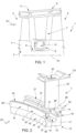
- Figure 11 is a section view, with part removed for clarity, of the sealing assembly of Figure 1 .
- a gas turbine engine comprising a stator 2 and a rotor 3 rotating about a longitudinal axis A1 with respect to the stator 2.
- the rotor 3 comprises a shaft 4 made of a number of axially clamped discs not shown the Figures; and a plurality of blade sets 5 (just two of them are shown in Figure 1 ) distributed along the longitudinal axis A1 and supported by the shaft 4.
- the stator 2 comprises a casing 6; and a plurality of vane sets 7 (just one shown in Figure 1 ). Each vane set 7 is interposed between two blade sets 5 and is supported by the casing 6.
- the inner ends of the vane 7 engage a respective U-shaped sealing ring 8, which is located in a corresponding annular cavity 9 of the shaft 4.
- the U-shaped sealing ring 8 together with the vanes 7 or the corresponding set defines a plenum 10.
- a dynamic seal 11 such as for example a labyrinth seal is arranged between the U-shaped sealing ring 8 and the shaft in the bottom of the cavity 8.
- a hot gas stream under high-pressure flows in direction D1 through the vanes 7 and the blades 5 and determines the rotation of the rotor 3 with respect to the stator 2.
- an airstream flows inside the vanes 7 to the plenum 10 and from the plenum 10 through the cavity 9.
- the U-shaped sealing ring 8 comprises a plurality of sealing assembly 12, which, in turn, comprises a U-shaped sector 13 and two adjacent cover plates 14 and is connected to a number of vanes 7 (just one them is shown in Figure 2 ).
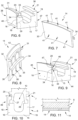
- Each U-shaped sector 13 comprises a bottom wall 15; an upstream wall 16; and a downstream wall 17 with reference to a direction D1 of the hot gases in the gas turbine engine 1 ( Figure 1 ).
- the upstream and downstream walls 16 and 17 comprises respective outer main faces 18 and 19 and respective circumferential faces 20 and 21.
- Each U-shaped sector 13 is shaped so as to engage the bottom of the vanes 7 so that the U-shaped sector 13 and the vanes 7 enclose the plenum 10.
- Each vane 7 comprises an airfoil 22, an outer shroud 23 and an inner shroud 24 coupled to the U-shaped sector 13.
- the airfoil 22 is provided with a cooling air duct 25 fed by a dedicated opening on the outer shroud 23.
- the inner shroud 24 comprises a platform 26, a leading edge flange 27 and a trailing edge flange 28 extending radially inward from the platform 26.
- the leading edge flange 27 is upstream the trailing edge flange 28 along the hot gas flow direction D1 and is coupled to the upstream wall 16 in a respective annular seat, while the trailing edge flange 28 is coupled to the downstream wall 17 in a respective annular seat.
- the upstream wall 16 is provided with at least one through hole 29 for conveying an airstream outside the plenum and, preferably, with a plurality of through holes 29 circumferentially distributed.
- Each cover plate 14 is configured for being coupled to the upstream wall 16 for channeling the airstream toward the platform 26.
- downstream wall is provided with a plurality of through holes circumferentially distributed and an additional cover plate is configured for being coupled to the upstream wall for channeling the airstream toward the platform.
- Each cover plate 14 is shaped as a sector and is arranged in contact with the main face 18 and the circumferential 20 face of the U-shaped sector 13.
- Each cover plate 14 comprises a main wall 30 facing the main face 18 and a circumferential wall 31 facing the circumferential face 20.
- each cover plate 14 comprises a circumferential baffle 32 protruding from the main wall 30 of the opposite side of the circumferential wall 31.
- the circumferential baffle 32 is coplanar with the circumferential wall 31.
- the upstream wall 16 has a retaining groove 33 extending from the main face 18 for housing a retaining profile 34 extending from the main wall 30 of the cover plate 14.
- the retaining groove 33 and the retaining profile 34 have a matching shape and preferably are L-shaped.
- each cover plate 14 comprises channels 35, which are configured to be, in use, in fluidic communication with the through holes 29.
- Each channel 35 extends along the main face 18 and the circumferential face 20 and is cut into the main wall 30 and circumferential wall 31 of the cover plate 14.
- each channel 35 comprises a blind groove cut into the main wall 30 and by an open groove, which is cut into the circumferential wall 31 and is in communication with the blind groove.
- the channel is open just at the end along the circumferential wall 31.
- each channel 35 is open at both ends.
- reference numeral 36 indicates a sealing assembly, which comprises a U-shaped sector 37 and a cover plate 38.
- the U-shaped sector 37 differentiates from the U-shaped sector 13 for the fact that hole 29 ( Figure 2 ) are replaced by through holes 39. For this reason, the other parts of the U-shaped sector 37 will be indicated with the same reference numerals for indicating corresponding parts of the U-shaped sector 13 ( Figure 2 ).
- the through holes 39 end in proximity of the bottom wall 15 and, for this reason, the cover plate 38 covers a greater portion of the main face 18.
- the cover plate 38 differentiates from the cover plate 14 for the fact that is provided with a main wall 40 larger than the main wall 30 shown in Figure 2 .
- the other parts of cover wall 38 are indicated with the same reference numerals indicating the corresponding parts of cover plate 14 ( Figure 2 ).
- the cover plate 14 comprises through openings 41 in fluidic communication with respective channels 35 ( Figure 4 ).
- the through openings 41 are located along the main wall 30 and/or the circumferential wall 31.
- cover plate 14 comprises a radial baffle 42 protruding from the circumferential wall 31.
- the radial baffle 42 is substantially coplanar with the main wall 30.
- a sealing assembly which comprises a U-shaped sector 44 and a cover plate 45.
- the U-shaped sector 44 differentiates from the U-shaped sector 13 ( Figure 2 ) for the fact that it comprises one additional retaining groove 46 parallel to retaining groove 33.
- cover plate 45 differentiates from the cover plate 14 for the fact that it comprises an additional retaining profile 47 parallel to retaining profile 34.
- the sealing assembly differentiates from the previous embodiments in the through holes 48 made in the leading flange 27.
- Through holes 48 made in the leading flange 27 could be either in addition to the through holes in the U-shaped sector or just the sole through holes for evacuating the air from plenum 10.
- the cover plate 49 has the function of guiding, in particular deflecting, the airstream flowing from plenum 10.
- the through holes are made in the trailing flange.
Landscapes
- Engineering & Computer Science (AREA)
- Mechanical Engineering (AREA)
- General Engineering & Computer Science (AREA)
- Physics & Mathematics (AREA)
- Fluid Mechanics (AREA)
- Turbine Rotor Nozzle Sealing (AREA)
Claims (15)
- Dichtungsanordnung für den Eingriff mit einer Anzahl von Schaufeln einer Gasturbinenmaschine, wobei die Dichtungsanordnung einen U-förmigen Sektor (13; 37; 44) umfasst, der für den Eingriff mit wenigstens einer Leitschaufel (7) konfiguriert ist, so dass der U-förmige Sektor (13; 37; 44) und die Leitschaufel (7) eine Luftkammer (10) umschließen, die mit dem Äußeren über wenigstens ein Durchgangsloch (29; 39; 48) in Verbindung steht, um einen Luftstrom nach außerhalb der Luftkammer (10) zu befördern; wobei die Dichtungsanordnung ferner wenigstens eine Abdeckplatte (14; 38; 45; 49) umfasst, die dazu konfiguriert ist, mit dem U-förmigen Sektor (13; 37; 44) gekoppelt zu werden, um den Luftstrom in eine vorgegebene Richtung zu führen, wobei die Dichtungsanordnung dadurch gekennzeichnet ist, dass der U-förmige Sektor (13; 37; 44) mit dem wenigstens einen Durchgangsloch (29; 39) versehen ist.
- Dichtungsanordnung nach Anspruch 1, wobei der U-förmige Sektor (13; 37; 44) eine stromaufwärts gelegene Wand (16) und eine stromabwärts gelegene Wand (17) umfasst, die mit jeweiligen Hauptflächen (18, 19) und jeweiligen Umfangsflächen (20, 21) versehen sind.
- Dichtungsanordnung nach Anspruch 2, wobei die wenigstens eine Abdeckplatte (14; 38; 45) dazu konfiguriert ist, mit der stromaufwärts gelegenen Wand (16) und/oder der stromabwärts gelegenen Wand (17) gekoppelt zu werden.
- Dichtungsanordnung nach Anspruch 2 oder 3, wobei die Abdeckplatte (14; 38; 45) entlang der Hauptfläche (18; 19) und der Umfangsfläche (20; 21) in Kontakt mit dem U-förmigen Sektor steht.
- Dichtungsanordnung nach einem der Ansprüche 2 bis 4, wobei die Abdeckplatte (14; 38; 45) eine Hauptwand (30; 40) in Kontakt mit der Hauptfläche (18; 19) und eine Umfangswand (31), die der Umfangsfläche (20; 21) gegenüberliegt, umfasst.
- Dichtungsanordnung nach Anspruch 5, wobei die Abdeckplatte (14; 38; 45) eine umlaufende Ablenkplatte (32) umfasst, wobei insbesondere die umlaufende Ablenkplatte (32) in entgegengesetzter Richtung zur umlaufenden Wand (31) von der Hauptwand (30; 40) hervorsteht, wobei insbesondere die umlaufende Ablenkplatte (32) koplanar mit der umlaufenden Wand (31) ist.
- Dichtungsanordnung nach Anspruch 3 oder 4, wobei die Abdeckplatte (14) eine radiale Ablenkplatte (42) umfasst, wobei insbesondere die radiale Ablenkplatte (42) von der Umfangswand (31) hervorsteht und koplanar mit der Hauptwand ist.
- Dichtungsanordnung nach einem der vorangehenden Ansprüche, wobei der U-förmige Sektor (13; 37; 44) wenigstens eine Haltenut (33) aufweist und die Abdeckplatte (14; 38; 45) wenigstens ein Halteprofil (34) zum Eingriff in die Haltenut (33) aufweist, wobei insbesondere die Haltenut (33) und das Halteprofil (34) zueinander passende Formen aufweisen und vorzugsweise L-förmig sind.
- Dichtungsanordnung nach Anspruch 8, wobei der U-förmige Sektor (44) eine weitere Haltenut (46) parallel zu der Haltenut (33) aufweist und die Abdeckplatte (45) ein weiteres Halteprofil (47) parallel zu dem Halteprofil (34) aufweist, wobei insbesondere die weitere Haltenut (46) und das weitere Halteprofil (47) zueinander passende Formen aufweisen und vorzugsweise L-förmig sind.
- Dichtungsanordnung nach einem der Ansprüche 1 bis 9, wobei die Abdeckplatte (14; 38; 45) wenigstens einen Kanal (35) umfasst, der mit dem Durchgangsloch (29; 39) in Fluidverbindung steht, wobei der Kanal (35) vorzugsweise in die Abdeckplatte (14; 38; 45) geschnitten ist.
- Dichtungsanordnung nach Anspruch 10, wobei der Kanal (35) an einem freien Ende entlang eines Randes der Abdeckplatte (14; 38; 45) offen ist.
- Dichtungsanordnung nach Anspruch 10 oder 11, wobei der Kanal (35) an zwei freien Enden entlang der Ränder der Abdeckplatte (14) offen ist.
- Dichtungsanordnung nach Anspruch 10 oder 11, wobei die Abdeckplatte (14) wenigstens eine Durchgangsöffnung (41) umfasst, die in Fluidverbindung mit dem Kanal (35) steht.
- Dichtungsanordnung nach einem der vorangehenden Ansprüche, die mehrere benachbarte Abdeckplatten umfasst und so geformt ist, dass diese an ihren jeweiligen Enden teilweise übereinander liegen.
- Gasturbinenmaschine, umfassend einen Stator (2) und einen Rotor (3), der dazu konfiguriert ist, um eine Längsachse (A) zu rotieren; wobei der Stator (2) mehrere Leitschaufelsätze (7) umfasst, die entlang der Längsachse (A) verteilt sind, und der Rotor (3) mehrere Schaufelsätze (5) umfasst, die entlang der Längsachse (A) verteilt sind und mit den Leitschaufelsätzen (7) alternieren, wobei wenigstens ein Leitschaufelsatz mit einem jeweiligen Dichtungsring in Eingriff steht, der mehrere Dichtungsanordnungen (12; 36; 43) nach einem der vorangehenden Ansprüche umfasst, die miteinander verbunden sind.
Priority Applications (2)
| Application Number | Priority Date | Filing Date | Title |
|---|---|---|---|
| EP20425060.9A EP4019742B1 (de) | 2020-12-23 | 2020-12-23 | Dichtungsanordnung für einen schaufelsatz eines gasturbinenmotors und gasturbinenmotor mit einer solchen dichtungsanordnung |
| CN202111586244.9A CN114658495A (zh) | 2020-12-23 | 2021-12-23 | 密封组件和包括这种密封组件的燃气涡轮发动机 |
Applications Claiming Priority (1)
| Application Number | Priority Date | Filing Date | Title |
|---|---|---|---|
| EP20425060.9A EP4019742B1 (de) | 2020-12-23 | 2020-12-23 | Dichtungsanordnung für einen schaufelsatz eines gasturbinenmotors und gasturbinenmotor mit einer solchen dichtungsanordnung |
Publications (2)
| Publication Number | Publication Date |
|---|---|
| EP4019742A1 EP4019742A1 (de) | 2022-06-29 |
| EP4019742B1 true EP4019742B1 (de) | 2024-10-23 |
Family
ID=74194499
Family Applications (1)
| Application Number | Title | Priority Date | Filing Date |
|---|---|---|---|
| EP20425060.9A Active EP4019742B1 (de) | 2020-12-23 | 2020-12-23 | Dichtungsanordnung für einen schaufelsatz eines gasturbinenmotors und gasturbinenmotor mit einer solchen dichtungsanordnung |
Country Status (2)
| Country | Link |
|---|---|
| EP (1) | EP4019742B1 (de) |
| CN (1) | CN114658495A (de) |
Families Citing this family (1)
| Publication number | Priority date | Publication date | Assignee | Title |
|---|---|---|---|---|
| GB2639240A (en) * | 2024-03-13 | 2025-09-17 | Rolls Royce Plc | Shroud of gas turbine engine and method of manufacturing thereof |
Family Cites Families (6)
| Publication number | Priority date | Publication date | Assignee | Title |
|---|---|---|---|---|
| JP3182343B2 (ja) * | 1996-07-09 | 2001-07-03 | 株式会社日立製作所 | ガスタービン静翼及びガスタービン |
| DE59709701D1 (de) * | 1997-09-15 | 2003-05-08 | Alstom Switzerland Ltd | Plattformkühlung für Gasturbinen |
| EP3094822B1 (de) * | 2014-01-13 | 2021-10-06 | Ansaldo Energia S.p.A. | Schaufel für eine gasturbine und verfahren zur herstellung einer solchen schaufel |
| US10451084B2 (en) * | 2015-11-16 | 2019-10-22 | General Electric Company | Gas turbine engine with vane having a cooling inlet |
| KR102028591B1 (ko) * | 2018-01-08 | 2019-10-04 | 두산중공업 주식회사 | 터빈 베인 조립체 및 이를 포함하는 가스터빈 |
| EP3663522B1 (de) | 2018-12-07 | 2021-11-24 | ANSALDO ENERGIA S.p.A. | Statoranordnung für eine gasturbine und gasturbine mit dieser statoranordnung |
-
2020
- 2020-12-23 EP EP20425060.9A patent/EP4019742B1/de active Active
-
2021
- 2021-12-23 CN CN202111586244.9A patent/CN114658495A/zh active Pending
Also Published As
| Publication number | Publication date |
|---|---|
| CN114658495A (zh) | 2022-06-24 |
| EP4019742A1 (de) | 2022-06-29 |
Similar Documents
| Publication | Publication Date | Title |
|---|---|---|
| EP1939404A2 (de) | Statoranordnung | |
| US4425079A (en) | Air sealing for turbomachines | |
| EP2948641B1 (de) | Dichtungsanordnung in einem gasturbinenmotor mit nuten in einer radial nach aussen gewandten seite einer plattform und einer nach innen gewandten seite eines innendeckbands | |
| US8939711B2 (en) | Outer rim seal assembly in a turbine engine | |
| US9328926B2 (en) | Segmented combustion chamber head | |
| EP2623728B1 (de) | Turbine mit variabler geometrie | |
| JP2016125486A (ja) | ガスタービンシール | |
| US20180171804A1 (en) | Turbine rotor blade arrangement for a gas turbine and method for the provision of sealing air in a turbine rotor blade arrangement | |
| CN108060979B (zh) | 燃气轮机及其旋流装置 | |
| US11585230B2 (en) | Assembly for a turbomachine | |
| CN108071492B (zh) | 燃气轮机及其预旋分流装置 | |
| EP2649279B1 (de) | Strömungsmaschine, insbesondere von einem heissen gasstrom axial durchdrungene gasturbine | |
| US20220003127A1 (en) | Sealing between a rotor disc and a stator of a turbomachine | |
| EP4019742B1 (de) | Dichtungsanordnung für einen schaufelsatz eines gasturbinenmotors und gasturbinenmotor mit einer solchen dichtungsanordnung | |
| EP2713009B1 (de) | Kühlverfahren und -system zur Kühlung von Schaufeln mindestens einer Schaufelreihe in einer drehenden Strömungsmaschine | |
| EP2715144B1 (de) | Leicht anpassbare verdichterzapfluft-vorrichtung stromab einer leitschaufelplattform | |
| CN108884714A (zh) | 包括通风间隔件的涡轮转子 | |
| EP3287605B1 (de) | Kranzdichtung für gasturbinenmotor | |
| EP3663522B1 (de) | Statoranordnung für eine gasturbine und gasturbine mit dieser statoranordnung | |
| EP3816405B1 (de) | Statoranordnung für eine gasturbine und gasturbine mit dieser statoranordnung | |
| US11428111B2 (en) | Device for cooling a turbomachine housing | |
| CN114981595B (zh) | 用于涡轮机的组合件 | |
| EP3816402B1 (de) | Statoranordnung für eine gasturbine und gasturbine mit dieser statoranordnung | |
| JP4913326B2 (ja) | シール構造及びタービンノズル | |
| US12467374B2 (en) | Turbine nozzle guide vane comprising an annular sealing element |
Legal Events
| Date | Code | Title | Description |
|---|---|---|---|
| PUAI | Public reference made under article 153(3) epc to a published international application that has entered the european phase |
Free format text: ORIGINAL CODE: 0009012 |
|
| STAA | Information on the status of an ep patent application or granted ep patent |
Free format text: STATUS: THE APPLICATION HAS BEEN PUBLISHED |
|
| AK | Designated contracting states |
Kind code of ref document: A1 Designated state(s): AL AT BE BG CH CY CZ DE DK EE ES FI FR GB GR HR HU IE IS IT LI LT LU LV MC MK MT NL NO PL PT RO RS SE SI SK SM TR |
|
| STAA | Information on the status of an ep patent application or granted ep patent |
Free format text: STATUS: REQUEST FOR EXAMINATION WAS MADE |
|
| 17P | Request for examination filed |
Effective date: 20221229 |
|
| RBV | Designated contracting states (corrected) |
Designated state(s): AL AT BE BG CH CY CZ DE DK EE ES FI FR GB GR HR HU IE IS IT LI LT LU LV MC MK MT NL NO PL PT RO RS SE SI SK SM TR |
|
| GRAP | Despatch of communication of intention to grant a patent |
Free format text: ORIGINAL CODE: EPIDOSNIGR1 |
|
| STAA | Information on the status of an ep patent application or granted ep patent |
Free format text: STATUS: GRANT OF PATENT IS INTENDED |
|
| P01 | Opt-out of the competence of the unified patent court (upc) registered |
Effective date: 20240430 |
|
| INTG | Intention to grant announced |
Effective date: 20240517 |
|
| GRAS | Grant fee paid |
Free format text: ORIGINAL CODE: EPIDOSNIGR3 |
|
| GRAA | (expected) grant |
Free format text: ORIGINAL CODE: 0009210 |
|
| STAA | Information on the status of an ep patent application or granted ep patent |
Free format text: STATUS: THE PATENT HAS BEEN GRANTED |
|
| AK | Designated contracting states |
Kind code of ref document: B1 Designated state(s): AL AT BE BG CH CY CZ DE DK EE ES FI FR GB GR HR HU IE IS IT LI LT LU LV MC MK MT NL NO PL PT RO RS SE SI SK SM TR |
|
| REG | Reference to a national code |
Ref country code: GB Ref legal event code: FG4D |
|
| REG | Reference to a national code |
Ref country code: CH Ref legal event code: EP |
|
| REG | Reference to a national code |
Ref country code: DE Ref legal event code: R096 Ref document number: 602020039831 Country of ref document: DE |
|
| REG | Reference to a national code |
Ref country code: IE Ref legal event code: FG4D |
|
| PGFP | Annual fee paid to national office [announced via postgrant information from national office to epo] |
Ref country code: DE Payment date: 20241216 Year of fee payment: 5 |
|
| REG | Reference to a national code |
Ref country code: LT Ref legal event code: MG9D |
|
| REG | Reference to a national code |
Ref country code: NL Ref legal event code: MP Effective date: 20241023 |
|
| REG | Reference to a national code |
Ref country code: AT Ref legal event code: MK05 Ref document number: 1734994 Country of ref document: AT Kind code of ref document: T Effective date: 20241023 |
|
| PG25 | Lapsed in a contracting state [announced via postgrant information from national office to epo] |
Ref country code: NL Free format text: LAPSE BECAUSE OF FAILURE TO SUBMIT A TRANSLATION OF THE DESCRIPTION OR TO PAY THE FEE WITHIN THE PRESCRIBED TIME-LIMIT Effective date: 20241023 |
|
| PG25 | Lapsed in a contracting state [announced via postgrant information from national office to epo] |
Ref country code: NL Free format text: LAPSE BECAUSE OF FAILURE TO SUBMIT A TRANSLATION OF THE DESCRIPTION OR TO PAY THE FEE WITHIN THE PRESCRIBED TIME-LIMIT Effective date: 20241023 |
|
| PG25 | Lapsed in a contracting state [announced via postgrant information from national office to epo] |
Ref country code: HR Free format text: LAPSE BECAUSE OF FAILURE TO SUBMIT A TRANSLATION OF THE DESCRIPTION OR TO PAY THE FEE WITHIN THE PRESCRIBED TIME-LIMIT Effective date: 20241023 Ref country code: IS Free format text: LAPSE BECAUSE OF FAILURE TO SUBMIT A TRANSLATION OF THE DESCRIPTION OR TO PAY THE FEE WITHIN THE PRESCRIBED TIME-LIMIT Effective date: 20250223 Ref country code: PT Free format text: LAPSE BECAUSE OF FAILURE TO SUBMIT A TRANSLATION OF THE DESCRIPTION OR TO PAY THE FEE WITHIN THE PRESCRIBED TIME-LIMIT Effective date: 20250224 |
|
| PG25 | Lapsed in a contracting state [announced via postgrant information from national office to epo] |
Ref country code: FI Free format text: LAPSE BECAUSE OF FAILURE TO SUBMIT A TRANSLATION OF THE DESCRIPTION OR TO PAY THE FEE WITHIN THE PRESCRIBED TIME-LIMIT Effective date: 20241023 |
|
| PG25 | Lapsed in a contracting state [announced via postgrant information from national office to epo] |
Ref country code: BG Free format text: LAPSE BECAUSE OF FAILURE TO SUBMIT A TRANSLATION OF THE DESCRIPTION OR TO PAY THE FEE WITHIN THE PRESCRIBED TIME-LIMIT Effective date: 20241023 |
|
| PG25 | Lapsed in a contracting state [announced via postgrant information from national office to epo] |
Ref country code: ES Free format text: LAPSE BECAUSE OF FAILURE TO SUBMIT A TRANSLATION OF THE DESCRIPTION OR TO PAY THE FEE WITHIN THE PRESCRIBED TIME-LIMIT Effective date: 20241023 |
|
| PG25 | Lapsed in a contracting state [announced via postgrant information from national office to epo] |
Ref country code: NO Free format text: LAPSE BECAUSE OF FAILURE TO SUBMIT A TRANSLATION OF THE DESCRIPTION OR TO PAY THE FEE WITHIN THE PRESCRIBED TIME-LIMIT Effective date: 20250123 |
|
| PG25 | Lapsed in a contracting state [announced via postgrant information from national office to epo] |
Ref country code: LV Free format text: LAPSE BECAUSE OF FAILURE TO SUBMIT A TRANSLATION OF THE DESCRIPTION OR TO PAY THE FEE WITHIN THE PRESCRIBED TIME-LIMIT Effective date: 20241023 Ref country code: AT Free format text: LAPSE BECAUSE OF FAILURE TO SUBMIT A TRANSLATION OF THE DESCRIPTION OR TO PAY THE FEE WITHIN THE PRESCRIBED TIME-LIMIT Effective date: 20241023 Ref country code: GR Free format text: LAPSE BECAUSE OF FAILURE TO SUBMIT A TRANSLATION OF THE DESCRIPTION OR TO PAY THE FEE WITHIN THE PRESCRIBED TIME-LIMIT Effective date: 20250124 |
|
| PG25 | Lapsed in a contracting state [announced via postgrant information from national office to epo] |
Ref country code: PL Free format text: LAPSE BECAUSE OF FAILURE TO SUBMIT A TRANSLATION OF THE DESCRIPTION OR TO PAY THE FEE WITHIN THE PRESCRIBED TIME-LIMIT Effective date: 20241023 |
|
| PGFP | Annual fee paid to national office [announced via postgrant information from national office to epo] |
Ref country code: IT Payment date: 20250207 Year of fee payment: 5 |
|
| PG25 | Lapsed in a contracting state [announced via postgrant information from national office to epo] |
Ref country code: RS Free format text: LAPSE BECAUSE OF FAILURE TO SUBMIT A TRANSLATION OF THE DESCRIPTION OR TO PAY THE FEE WITHIN THE PRESCRIBED TIME-LIMIT Effective date: 20250123 |
|
| PG25 | Lapsed in a contracting state [announced via postgrant information from national office to epo] |
Ref country code: SM Free format text: LAPSE BECAUSE OF FAILURE TO SUBMIT A TRANSLATION OF THE DESCRIPTION OR TO PAY THE FEE WITHIN THE PRESCRIBED TIME-LIMIT Effective date: 20241023 |
|
| PG25 | Lapsed in a contracting state [announced via postgrant information from national office to epo] |
Ref country code: MC Free format text: LAPSE BECAUSE OF FAILURE TO SUBMIT A TRANSLATION OF THE DESCRIPTION OR TO PAY THE FEE WITHIN THE PRESCRIBED TIME-LIMIT Effective date: 20241023 |
|
| PG25 | Lapsed in a contracting state [announced via postgrant information from national office to epo] |
Ref country code: DK Free format text: LAPSE BECAUSE OF FAILURE TO SUBMIT A TRANSLATION OF THE DESCRIPTION OR TO PAY THE FEE WITHIN THE PRESCRIBED TIME-LIMIT Effective date: 20241023 |
|
| PG25 | Lapsed in a contracting state [announced via postgrant information from national office to epo] |
Ref country code: EE Free format text: LAPSE BECAUSE OF FAILURE TO SUBMIT A TRANSLATION OF THE DESCRIPTION OR TO PAY THE FEE WITHIN THE PRESCRIBED TIME-LIMIT Effective date: 20241023 |
|
| PG25 | Lapsed in a contracting state [announced via postgrant information from national office to epo] |
Ref country code: RO Free format text: LAPSE BECAUSE OF FAILURE TO SUBMIT A TRANSLATION OF THE DESCRIPTION OR TO PAY THE FEE WITHIN THE PRESCRIBED TIME-LIMIT Effective date: 20241023 |
|
| REG | Reference to a national code |
Ref country code: DE Ref legal event code: R097 Ref document number: 602020039831 Country of ref document: DE |
|
| PG25 | Lapsed in a contracting state [announced via postgrant information from national office to epo] |
Ref country code: SK Free format text: LAPSE BECAUSE OF FAILURE TO SUBMIT A TRANSLATION OF THE DESCRIPTION OR TO PAY THE FEE WITHIN THE PRESCRIBED TIME-LIMIT Effective date: 20241023 |
|
| PG25 | Lapsed in a contracting state [announced via postgrant information from national office to epo] |
Ref country code: CZ Free format text: LAPSE BECAUSE OF FAILURE TO SUBMIT A TRANSLATION OF THE DESCRIPTION OR TO PAY THE FEE WITHIN THE PRESCRIBED TIME-LIMIT Effective date: 20241023 |
|
| REG | Reference to a national code |
Ref country code: CH Ref legal event code: PL |
|
| PG25 | Lapsed in a contracting state [announced via postgrant information from national office to epo] |
Ref country code: LU Free format text: LAPSE BECAUSE OF NON-PAYMENT OF DUE FEES Effective date: 20241223 |
|
| PLBE | No opposition filed within time limit |
Free format text: ORIGINAL CODE: 0009261 |
|
| STAA | Information on the status of an ep patent application or granted ep patent |
Free format text: STATUS: NO OPPOSITION FILED WITHIN TIME LIMIT |
|
| PG25 | Lapsed in a contracting state [announced via postgrant information from national office to epo] |
Ref country code: SE Free format text: LAPSE BECAUSE OF FAILURE TO SUBMIT A TRANSLATION OF THE DESCRIPTION OR TO PAY THE FEE WITHIN THE PRESCRIBED TIME-LIMIT Effective date: 20241023 |
|
| GBPC | Gb: european patent ceased through non-payment of renewal fee |
Effective date: 20250123 |
|
| 26N | No opposition filed |
Effective date: 20250724 |
|
| REG | Reference to a national code |
Ref country code: BE Ref legal event code: MM Effective date: 20241231 |
|
| PG25 | Lapsed in a contracting state [announced via postgrant information from national office to epo] |
Ref country code: BE Free format text: LAPSE BECAUSE OF NON-PAYMENT OF DUE FEES Effective date: 20241231 Ref country code: GB Free format text: LAPSE BECAUSE OF NON-PAYMENT OF DUE FEES Effective date: 20250123 |
|
| PG25 | Lapsed in a contracting state [announced via postgrant information from national office to epo] |
Ref country code: FR Free format text: LAPSE BECAUSE OF NON-PAYMENT OF DUE FEES Effective date: 20241223 |
|
| PG25 | Lapsed in a contracting state [announced via postgrant information from national office to epo] |
Ref country code: CH Free format text: LAPSE BECAUSE OF NON-PAYMENT OF DUE FEES Effective date: 20241231 |
|
| PG25 | Lapsed in a contracting state [announced via postgrant information from national office to epo] |
Ref country code: IE Free format text: LAPSE BECAUSE OF NON-PAYMENT OF DUE FEES Effective date: 20241223 |