EP4019451A1 - Aufzugsgegengewichtsanordnung zur energierückgewinnung und entsprechendes aufzugssystem - Google Patents
Aufzugsgegengewichtsanordnung zur energierückgewinnung und entsprechendes aufzugssystem Download PDFInfo
- Publication number
- EP4019451A1 EP4019451A1 EP20216580.9A EP20216580A EP4019451A1 EP 4019451 A1 EP4019451 A1 EP 4019451A1 EP 20216580 A EP20216580 A EP 20216580A EP 4019451 A1 EP4019451 A1 EP 4019451A1
- Authority
- EP
- European Patent Office
- Prior art keywords
- assembly
- module
- motion
- generators
- assembly according
- Prior art date
- Legal status (The legal status is an assumption and is not a legal conclusion. Google has not performed a legal analysis and makes no representation as to the accuracy of the status listed.)
- Granted
Links
Images

Classifications
-
- B—PERFORMING OPERATIONS; TRANSPORTING
- B66—HOISTING; LIFTING; HAULING
- B66B—ELEVATORS; ESCALATORS OR MOVING WALKWAYS
- B66B1/00—Control systems of elevators in general
- B66B1/24—Control systems with regulation, i.e. with retroactive action, for influencing travelling speed, acceleration, or deceleration
- B66B1/28—Control systems with regulation, i.e. with retroactive action, for influencing travelling speed, acceleration, or deceleration electrical
- B66B1/285—Control systems with regulation, i.e. with retroactive action, for influencing travelling speed, acceleration, or deceleration electrical with the use of a speed pattern generator
-
- B—PERFORMING OPERATIONS; TRANSPORTING
- B66—HOISTING; LIFTING; HAULING
- B66B—ELEVATORS; ESCALATORS OR MOVING WALKWAYS
- B66B17/00—Hoistway equipment
- B66B17/12—Counterpoises
-
- B—PERFORMING OPERATIONS; TRANSPORTING
- B66—HOISTING; LIFTING; HAULING
- B66B—ELEVATORS; ESCALATORS OR MOVING WALKWAYS
- B66B11/00—Main component parts of lifts in, or associated with, buildings or other structures
- B66B11/04—Driving gear ; Details thereof, e.g. seals
-
- B—PERFORMING OPERATIONS; TRANSPORTING
- B66—HOISTING; LIFTING; HAULING
- B66B—ELEVATORS; ESCALATORS OR MOVING WALKWAYS
- B66B9/00—Kinds or types of lifts in, or associated with, buildings or other structures
-
- H—ELECTRICITY
- H02—GENERATION; CONVERSION OR DISTRIBUTION OF ELECTRIC POWER
- H02J—ELECTRIC POWER NETWORKS; CIRCUIT ARRANGEMENTS OR SYSTEMS FOR SUPPLYING OR DISTRIBUTING ELECTRIC POWER; SYSTEMS FOR STORING ELECTRIC ENERGY
- H02J7/00—Circuit arrangements for charging or discharging batteries or for supplying loads from batteries
- H02J7/14—Circuit arrangements for charging or discharging batteries or for supplying loads from batteries for charging batteries from dynamo-electric generators driven at varying speed, e.g. on vehicle
- H02J7/1415—Circuit arrangements for charging or discharging batteries or for supplying loads from batteries for charging batteries from dynamo-electric generators driven at varying speed, e.g. on vehicle with a generator driven by a prime mover other than the motor of a vehicle
-
- H—ELECTRICITY
- H02—GENERATION; CONVERSION OR DISTRIBUTION OF ELECTRIC POWER
- H02J—ELECTRIC POWER NETWORKS; CIRCUIT ARRANGEMENTS OR SYSTEMS FOR SUPPLYING OR DISTRIBUTING ELECTRIC POWER; SYSTEMS FOR STORING ELECTRIC ENERGY
- H02J7/00—Circuit arrangements for charging or discharging batteries or for supplying loads from batteries
- H02J7/14—Circuit arrangements for charging or discharging batteries or for supplying loads from batteries for charging batteries from dynamo-electric generators driven at varying speed, e.g. on vehicle
- H02J7/1423—Circuit arrangements for charging or discharging batteries or for supplying loads from batteries for charging batteries from dynamo-electric generators driven at varying speed, e.g. on vehicle with multiple batteries
-
- H—ELECTRICITY
- H02—GENERATION; CONVERSION OR DISTRIBUTION OF ELECTRIC POWER
- H02J—ELECTRIC POWER NETWORKS; CIRCUIT ARRANGEMENTS OR SYSTEMS FOR SUPPLYING OR DISTRIBUTING ELECTRIC POWER; SYSTEMS FOR STORING ELECTRIC ENERGY
- H02J7/00—Circuit arrangements for charging or discharging batteries or for supplying loads from batteries
- H02J7/14—Circuit arrangements for charging or discharging batteries or for supplying loads from batteries for charging batteries from dynamo-electric generators driven at varying speed, e.g. on vehicle
- H02J7/1469—Regulation of the charging current or voltage otherwise than by variation of field
- H02J7/1492—Regulation of the charging current or voltage otherwise than by variation of field by means of controlling devices between the generator output and the battery
-
- H—ELECTRICITY
- H02—GENERATION; CONVERSION OR DISTRIBUTION OF ELECTRIC POWER
- H02J—ELECTRIC POWER NETWORKS; CIRCUIT ARRANGEMENTS OR SYSTEMS FOR SUPPLYING OR DISTRIBUTING ELECTRIC POWER; SYSTEMS FOR STORING ELECTRIC ENERGY
- H02J7/00—Circuit arrangements for charging or discharging batteries or for supplying loads from batteries
- H02J7/34—Parallel operation in networks using both storage and other DC sources, e.g. providing buffering
- H02J7/345—Parallel operation in networks using both storage and other DC sources, e.g. providing buffering using capacitors as storage or buffering devices
-
- H—ELECTRICITY
- H02—GENERATION; CONVERSION OR DISTRIBUTION OF ELECTRIC POWER
- H02K—DYNAMO-ELECTRIC MACHINES
- H02K7/00—Arrangements for handling mechanical energy structurally associated with dynamo-electric machines, e.g. structural association with mechanical driving motors or auxiliary dynamo-electric machines
- H02K7/06—Means for converting reciprocating motion into rotary motion or vice versa
-
- H—ELECTRICITY
- H02—GENERATION; CONVERSION OR DISTRIBUTION OF ELECTRIC POWER
- H02K—DYNAMO-ELECTRIC MACHINES
- H02K7/00—Arrangements for handling mechanical energy structurally associated with dynamo-electric machines, e.g. structural association with mechanical driving motors or auxiliary dynamo-electric machines
- H02K7/10—Structural association with clutches, brakes, gears, pulleys or mechanical starters
- H02K7/116—Structural association with clutches, brakes, gears, pulleys or mechanical starters with gears
- H02K7/1163—Structural association with clutches, brakes, gears, pulleys or mechanical starters with gears where at least two gears have non-parallel axes without having orbital motion
- H02K7/1166—Structural association with clutches, brakes, gears, pulleys or mechanical starters with gears where at least two gears have non-parallel axes without having orbital motion comprising worm and worm-wheel
-
- H—ELECTRICITY
- H02—GENERATION; CONVERSION OR DISTRIBUTION OF ELECTRIC POWER
- H02K—DYNAMO-ELECTRIC MACHINES
- H02K7/00—Arrangements for handling mechanical energy structurally associated with dynamo-electric machines, e.g. structural association with mechanical driving motors or auxiliary dynamo-electric machines
- H02K7/18—Structural association of electric generators with mechanical driving motors, e.g. with turbines
- H02K7/1807—Rotary generators
- H02K7/1846—Rotary generators structurally associated with wheels or associated parts
-
- B—PERFORMING OPERATIONS; TRANSPORTING
- B66—HOISTING; LIFTING; HAULING
- B66B—ELEVATORS; ESCALATORS OR MOVING WALKWAYS
- B66B1/00—Control systems of elevators in general
- B66B1/24—Control systems with regulation, i.e. with retroactive action, for influencing travelling speed, acceleration, or deceleration
- B66B1/28—Control systems with regulation, i.e. with retroactive action, for influencing travelling speed, acceleration, or deceleration electrical
- B66B1/30—Control systems with regulation, i.e. with retroactive action, for influencing travelling speed, acceleration, or deceleration electrical effective on driving gear, e.g. acting on power electronics, on inverter or rectifier controlled motor
- B66B1/302—Control systems with regulation, i.e. with retroactive action, for influencing travelling speed, acceleration, or deceleration electrical effective on driving gear, e.g. acting on power electronics, on inverter or rectifier controlled motor for energy saving
Definitions
- Various example embodiments relate generally to a system and a device for energy recovery.
- the invention applies in particular to the area of elevators.
- Elevator systems typically comprise a cabin and a counterweight, both being guided in an elevator shaft in opposite directions. Both the cabin and counterweight are mechanically connected by one or more hoist ropes, for example steel ropes, slung over a grooved drive sheave the axle of which is connected to a gear box and an electrical motor in order to enable rotation of the drive sheave at a desired speed an into the right direction.
- the counterweight may have a mass approx. equal to that of the cabin, to which about half the maximum load of the cabin is added.
- the energy consumption required by the elevator system to move the cabin up and down depends among other things on the relative weight of the cabin and its load (i.e. its occupancy) compared to the counterweight.
- an elevator counterweight assembly comprises:
- the counterweight comprises mechanical and electrical components allowing energy recovery when the counterweight moves. Electrical power generation and storage modules are housed in the counterweight and thus replace inert weight used in conventional counterweights.
- said at least one mechanism for converting linear motion into rotatory motion comprises one among a bevel gear or a worm gear, wherein a first axis of said bevel gear or said worm gear is mechanically connected to a shaft of said at least one electric generator so as to induce a rotatory motion of said shaft of said at least one electric generator when said first axis rotates.
- a second axis of said bevel gear or worm gear is connected to a wheel such that a rotation of said wheel induces rotation of said second axis, said wheel being adapted to be in contact with a surface parallel to a direction of motion of said assembly, so that said wheel rotates when said assembly is in motion.
- said surface is part of, or fixed to, a mechanical guide for said assembly, for guiding the assembly in its linear motion.
- said accumulator module comprises at least one among: at least one super capacitor; at least one ultra-capacitor; at least one battery.
- the assembly further comprises a power transfer module for discharging said at least one accumulator to an electric power sink external to said assembly.
- said power transfer module comprises at least one among:
- said electrical energy generator module comprises at least one plurality of generators, the shafts of said at least one plurality of generators being mechanically connected to form an alignment such that rotating the shaft of one generator induces rotation of the shaft of the other generators of said plurality of generators, wherein at least one shaft of the generators of said alignment is connected to one of said at least one mechanisms for converting a linear motion of said assembly into a rotatory motion.
- said alignment of generators is arranged along a direction which is parallel or orthogonal compared to the intended direction of motion of said assembly.
- the assembly further comprises a plurality of alignments of generators arranged along parallel and/or orthogonal directions.
- respective mechanisms for converting a linear motion into a rotatory motion are provided at a first and a second shaft respectively at each extremity of an alignment of generators.
- the assembly further comprises at least one among: means for engaging and disengaging an element of said at least one mechanism for converting a linear motion of said assembly into a rotatory motion; a switch for opening and closing an electrical circuit for connecting and disconnecting all or part of the generators of said energy generator module from said accumulator module.
- said mechanism for converting a linear motion of said assembly into a rotatory motion comprises as part of a chain of transmission of motion at least one among a kinetic flywheel module and a continuously variable transmission module.
- an elevator system comprising:
- Rope means can comprise one or more among: one or more ropes, one or more belts, one or more cables, one or more chains.
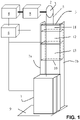
- FIG. 1 shows an elevator system according to an exemplary embodiment.
- the system according to this embodiment comprises a cabin 1, a drive sheave 2, a counterweight 3, a motor 4, a rope or set of ropes 5, a control unit 6, counterweight guiding members 7a and 7b and optionally a gear box 8.
- Cabin and counterweight are attached to a set of steel ropes 5 (only one rope is shown in FIG. 1 ) slung over the drive sheave 2 and prevented from slipping by appropriately formed grooves of the drive sheave 2.
- the term 'rope' is used to cover all possible alternatives to the function of the rope, i.e. allowing the motor to move cabin and counterweight into opposite direction.
- Alternatives may include for example one or more belts, one or more cables, one or more chains...
- the axis of the drive sheave 2 is connected to gear box 8, which in turn is connected to the axis of motor 4.
- Motor 4, gear box 8 (when present) and drive sheave 2 form a drive unit to move cabin 1 and counterweight 3 in opposite directions.
- the drive unit may be configured differently in other implementations (e.g. comprising more than one sheave).
- Control unit 6, which may comprise a processor, memory, software, a communication bus and appropriate control interfaces is connected to the different components of the system in order to allow control, status monitoring and fault processing. Although the control unit 6 is shown as a central unit, the different components may comprise their own control unit, partially or complete replacing the functions of the central control unit 6.
- the outlines 9 of the bottom of the elevator system shaft are also shown.
- counterweight 3 is guided by lateral guiding members 7a and 7b (such as steel rods or rails) which are for example fixed to the vertical walls of the elevator system shaft.
- counterweight 3 comprises a frame 10 housing an electrical energy generator module 11, an accumulator module 12 and one or more weights 13.
- FIG. 1 simply provides an overview of some components located on the counterweight 3.
- the combined weight of the frame 10, the generator module 11, the accumulator module, the weights 13 and possibly other components located on the counterweight are taken into account for calculating the overall weight of the counterweight needed within the elevator system.
- the generator module, the accumulator module and the weights are constructed in a modular fashion.
- the accumulator module may be expanded by adding accumulator elements for additional storage capacity, and as a consequence, some weights may be removed to maintain an appropriate overall weight of the counterweight.
- additional generators may be provided.
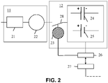
- FIG. 2 is a schematic block diagram of the energy generator module 11, the accumulator module 12 and additional components used to schematically explain how electrical energy is recovered, stored and conveyed for further use according to one exemplary embodiment.
- the energy generator module 11 comprises a linear-to-rotary motion conversion mechanism 21 connected to the axis of an electrical generator 22.
- the function of mechanism 21 is to convert the linear motion of the counterweight 3 to a rotary motion capable of rotating the axis of generator 22, directly or through one or more intermediary modules.
- the function of the generator 22 is to produce electrical power to feed the accumulator module 12.
- Energy generator module 11 may comprise one or more mechanisms 21 and one or more generators 22. Several exemplary embodiments will be described later.
- the energy generator module may comprise additional sub-modules.
- the linear-to-rotary motion conversion mechanism 21 may be connected to a step-up gear box to increase the speed of rotation of the generator shaft compared to the output of the linear-to-rotary motion conversion mechanism 21.
- the linear-to-rotary motion conversion mechanism 21 may also or in addition be connected to the generator shaft through a continuously variable transmission, to provide a substantially constant speed of rotation to the generator shaft.
- a kinetic flywheel is placed in the chain of elements providing the rotary motion to the generator. The function of the flywheel is to store energy when being rotated by another element of mechanism 21 (e.g.
- the energy generator module comprises actuator means that enable mechanical disengagement and reengagement of an element of its element chain. This enables reducing or eliminating the braking effect on the motion of the counterweight when so desired.
- the accumulator module comprises a battery management unit 23 which controls charging and discharging of accumulator elements.
- these accumulator elements comprise at least one capacitor (illustrated by element 24) and/or at least one battery (illustrated by element 25).
- the capacitor 24 can for example be a super- or ultra-capacitor.
- Battery management unit 23 monitors charging levels of the different accumulator elements and switches the power received from generator 22 to the accumulator element(s) as appropriate.
- the battery management unit 23 is also configured to electrically disconnect the accumulator module, entirely or element-by-element from the generator module 22 when certain conditions are met - this is schematically illustrated by switch 28.
- generators may be disconnected or reconnected, partly or entirely, when certain conditions are met. Such conditions may for example include one or more of: an accumulator element is fully loaded or when it is undesirable to recover energy from the motion of counterweight 3. Other conditions may apply.
- the accumulator comprises both capacitors and batteries.
- Battery management unit 23 comprises a processor running software for controlling the capacitors and / or batteries. It determines the available accumulator elements and assesses the efficiency level of each element with regard to the required needs. For example, capacitors may typically charge and discharge more rapidly than batteries, if both types of elements are available. The battery management system may thus decide to prioritize capacitors as its primary charge, respectively discharge elements, compared to batteries, relying on the latter only if the former are fully charged, respectively discharged.
- the battery management unit discharges capacitor accumulator elements into battery elements.
- the diagram of FIG. 2 also shows a power transfer module 26 which is connected to the accumulator module.
- the function of power transfer module 26 is to discharge the accumulator elements to a sink 27, such as the grid of a power grid operator and/or the power system of the building housing the elevator system and/or to batteries and/or to the elevator main motor 4. According to the present embodiment, this transfer is performed under control of the battery management system 23.
- Transfer module 26 may be implemented as a first induction mat cooperating with a second induction mat 27 when the counterweight is not moving and located at certain positions within the shaft, such as the extreme upper and lower positions.
- Transfer module 26 may comprise more than one induction mat - such induction mats may be placed at several locations on the counterweight so that they automatically are placed facing their counterparts 27 within the shaft at the different locations of the counterweight.
- battery management unit 23 may determine how accumulator elements are used as a function of information concerning elevator operation. Such information may include one or more of the following: the number of elevator calls to be answered, the distance for the elevator to travel to answer a call, the load of the cabin. Such information may be provided to the battery management unit 23 by control unit 6. For short runs with limited load, the battery management may prioritize capacitor elements, whereas for longer runs with high load, it may prioritize battery elements.
- the battery management unit 23 transfers power from the accumulator module to the elevator main motor as a function of the charge level of the accumulator module. Priority is given to the elevator main motor. E.g. if the accumulator module charge level is above below a threshold, power is transferred only to the elevator. Above the threshold, power is transferred to other sinks, such as the power grid. According to one embodiment, such a charge level may for example be 85% for batteries.
- the accumulator module is used solely to power the elevator main motor and this functions in a 'closed loop'.
- the elevator system also comprises conversion circuitry to convert the DC power provided by the accumulator elements to one or more sinks, e.g. when the accumulator elements provide power to the elevator main motor, the conversion circuitry may generate three-phase voltage.
- This conversion circuitry is not illustrated in the figures. Per se, power conversion circuitry is known to the Person Skilled in the Art and won't be described in more detail.
- transfer module 26 comprises electrical contacts which cooperate with electrical contacts of sink 27 to discharge the accumulator elements.
- frame 10 of counterweight 3 is adjustable in size according at least one direction.
- Frame 10 may also be referred to as a sling. Adjustment of the size allows taking into account different combinations of energy generator modules, accumulator modules and weights.
- the frame is adjustable along the direction of motion of the counterweight 3.
- the frame may comprise an upper frame element and a lower frame element.
- the upper frame element comprises an upper bar and two lateral bars respectively fixed to each end of the upper bar, to form an inverted U when in functioning position.
- the upper bar is destined to be attached to rope 5.
- the lower frame element comprises a lower bar and two lateral bars respectively fixed to each end of the lower bar, to form a U when in functioning position.
- Respective lateral bars of each of the upper and lower frame elements are destined to be fixed to form a rectangular frame.
- a pair of corresponding lateral bars may slide relative to each other so that a rectangular frame of adjustable size along the intended direction of motion is formed.
- Corresponding lateral bars may be fastened using appropriate means. For example, holes may be formed along the length of the lower frame element lateral bars at different positions corresponding to the different lengths of frame 10. Holes are also provided towards the extremity of the lateral bars of the upper frame element away from the upper bar. The lateral bars of the upper frame element and the lateral bars of the lower frame element are positioned so that the appropriate length of frame 10 is obtained and then fastened using fastening means such as bolts and nuts, with the bolts being placed through corresponding holes of a pair of corresponding lateral bars. Other interlocking means between corresponding lateral bars may be provided.
- the frame 10 is adjustable in width, e.g. to accommodate different shaft widths and/or different spacing of the counterweight guides 7a and 7b.
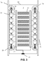
- FIG. 3 is a schematic diagram of a first embodiment of counterweight 3.
- the counterweight comprises at least one stack 31 of generators 22 vertically aligned along - and connected by - their shafts.
- FIG. 3 illustrates a counterweight with two such stacks, each one being placed along a respective side of the counterweight.
- Each stack is connected to one or more a linear-to-rotary motion conversion mechanisms 21.
- the generator shafts at each extremity of a stack are connected to a corresponding linear-to-rotary motion conversion mechanism 21. Stacking of the generators reduces the required number of such mechanisms.
- the counterweight further comprises an accumulator module 12 split into two columns of accumulator elements. The interconnection of these columns and the battery management unit are not shown in FIG.
- the generators 22 are connected to the accumulator module through appropriate wiring 30.
- the accumulator module is connected to contacts 32 allowing discharging of the accumulator elements under control of battery management unit 23 when the counterweight is in a given position (e.g. at its lowest position) and the contacts 32 touch corresponding contacts (not shown) external to the counterweight and connected to a power sink.
- the counterweight also comprises weights 13 under the form of a set of one or more weight bars.
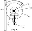
- FIG. 4 is a schematic diagram of a first embodiment of the linear-to-rotary motion conversion mechanism 21 which can be used in conjunction with the exemplary embodiment of FIG. 3 .
- Mechanism 21 comprises a wheel or roller 40 with an axis 41.
- roller 40 When in functioning position, roller 40 is placed against and in contact with guide 7a (or 7b) so that when the counterweight moves, the friction between the guide and the roller causes the roller to rotate around axis 41.
- a first gear 42 of a bevel gear assembly is fastened to axis 41. Rotation of first gear 42 causes rotation of a second gear 43 of the bevel gear assembly around axis 44.
- Axis 44 is fastened to the generator shaft (or, in variant embodiments, to an intermediate module, such as a kinetic flywheel, a continuously variable transmission, a gear box).
- the axes of the gears are placed at 90°, but depending on positioning and orientation of the other elements of the electrical energy generator module 11, the angle may be different.
- mechanism 21 comprises an actuator (not illustrated) to engage and disengage gears 42 and 43 of the bevel gear assembly.
- mechanism 21 comprises an actuator to separate wheel 40 from, or to reestablish contact with, guides 7a or 7b. Actuators may be under the control of battery management unit 23 (e.g. when accumulator module elements are fully charged) or central control unit 6 (when braking of the counterweight is not desired).
- the wheel 40 has a radius of 5 to 15 cm. At a speed of 5 m/s, wheel 40 then rotates between approx. 1000 and 3000 rpm.
- a generator weighing 25 kilograms produces between 3 and 5 kW with an efficiency of 90%
- a rotation speed of 2500 rpm a stack with six generators would weigh around 150 kilograms and would produce around 20 kW.
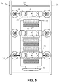
- FIG. 5 is a schematic diagram of a second embodiment of a counterweight 3.
- the counterweight comprises at least one stack 51 of generators 22 horizontally aligned along - and connected by - their shafts.
- FIG. 5 illustrates a counterweight with three such stacks, placed in parallel with the upper and lower bars of frame 10 of counterweight 3.
- Each stack is connected to one or more a linear-to-rotary motion conversion mechanisms 21.
- the generator shafts at each extremity of a stack are connected to a corresponding linear-to-rotary motion conversion mechanism 21.
- the counterweight further comprises an accumulator module 12 split into three packs of accumulator elements. The interconnection of these packs and the battery management unit are not shown in FIG. 5 .
- the generators 22 are connected to the accumulator module 12 through appropriate wiring 30.
- the counterweight also comprises weights 13 under the form of a set of one or more weight bars.
- the embodiment of FIG. 5 also comprises an induction mat 50 or another type of induction-based power transfer device that is connected to the packs of accumulator elements through appropriate wiring. Activation of the mat is controlled by battery control unit 23 (not shown). Mat 50 cooperates with a corresponding induction mat (not illustrated) placed in proximity of mat 50 when the counterweight is in its lowest position in the elevator shaft. More than one mat may be used.
- a similar induction-based power transfer module may be implemented with regard to the embodiment of FIG. 3 instead of the contacts shown in the first embodiment. Conversely, the contacts of the first embodiment of FIG. 3 may be used instead of the induction mat in the second embodiment of FIG. 5 .
- the Person Skilled in the Art may devise other modules for transferring power from the accumulator module to an external sink.
- FIG. 3 and FIG. 5 present two embodiments which use vertically and horizontally aligned generator stacks. Hybrid embodiments using both types of stacks may easily be devised by the Person Skilled in the Art. Also, generators or stacks thereof may be placed at an angle, with the linear-to-rotary motion conversion mechanisms 21 appropriately adapted.
- FIG. 6 illustrates a second embodiment of the linear-to-rotary motion conversion mechanism 21.
- Mechanism 21 comprises a wheel or roller 60 with an axis 61.
- roller 60 When in functioning position, roller 60 is placed against and in contact with one of the counterweight guides (not illustrated) so that when the counterweight moves, the friction between the guide and the roller causes the roller to rotate around axis 61.
- a gear wheel 62 is fastened to axis 61. Rotation of gear wheel 62 causes rotation of a threaded worm shaft 63, which extends axis 64.
- Axis 64 is fastened to shaft of generator 20, or an intermediate module.
- FIG. 6 The same variants mentioned in relation with the embodiment of FIG. 3 apply to the embodiment of FIG. 6 .
- the above embodiments concern a counterweight that moves along a vertical path.
- the principles described herein may easily be adapted to paths that are not vertical, e.g. to oblique paths, provided that the wheel of mechanism 21 can remain in contact with a surface in order to rotate when the counterweight moves along the path.
Landscapes
- Engineering & Computer Science (AREA)
- Power Engineering (AREA)
- Automation & Control Theory (AREA)
- Structural Engineering (AREA)
- Civil Engineering (AREA)
- Mechanical Engineering (AREA)
- Cage And Drive Apparatuses For Elevators (AREA)
- Elevator Control (AREA)
Priority Applications (5)
| Application Number | Priority Date | Filing Date | Title |
|---|---|---|---|
| EP20216580.9A EP4019451B1 (de) | 2020-12-22 | 2020-12-22 | Aufzugsgegengewichtsanordnung zur energierückgewinnung und entsprechendes aufzugssystem |
| KR1020210178652A KR20220090430A (ko) | 2020-12-22 | 2021-12-14 | 에너지 복구를 위한 엘리베이터 균형추 어셈블리 및 해당 엘리베이터 시스템 |
| JP2021203108A JP7786719B2 (ja) | 2020-12-22 | 2021-12-15 | エネルギー回収用のエレベータ用カウンターウエイトアセンブリおよび対応するエレベータシステム |
| US17/557,035 US20220194743A1 (en) | 2020-12-22 | 2021-12-20 | Elevator counterweight assembly for energy recovery and corresponding elevator system |
| CN202111578377.1A CN114655819A (zh) | 2020-12-22 | 2021-12-22 | 用于能量回收的电梯配重组件和相应的电梯系统 |
Applications Claiming Priority (1)
| Application Number | Priority Date | Filing Date | Title |
|---|---|---|---|
| EP20216580.9A EP4019451B1 (de) | 2020-12-22 | 2020-12-22 | Aufzugsgegengewichtsanordnung zur energierückgewinnung und entsprechendes aufzugssystem |
Publications (3)
| Publication Number | Publication Date |
|---|---|
| EP4019451A1 true EP4019451A1 (de) | 2022-06-29 |
| EP4019451C0 EP4019451C0 (de) | 2024-08-21 |
| EP4019451B1 EP4019451B1 (de) | 2024-08-21 |
Family
ID=74095685
Family Applications (1)
| Application Number | Title | Priority Date | Filing Date |
|---|---|---|---|
| EP20216580.9A Active EP4019451B1 (de) | 2020-12-22 | 2020-12-22 | Aufzugsgegengewichtsanordnung zur energierückgewinnung und entsprechendes aufzugssystem |
Country Status (5)
| Country | Link |
|---|---|
| US (1) | US20220194743A1 (de) |
| EP (1) | EP4019451B1 (de) |
| JP (1) | JP7786719B2 (de) |
| KR (1) | KR20220090430A (de) |
| CN (1) | CN114655819A (de) |
Cited By (1)
| Publication number | Priority date | Publication date | Assignee | Title |
|---|---|---|---|---|
| EP4578811A1 (de) | 2023-12-26 | 2025-07-02 | EleVolt Ltd | Schachtaufzugssystem mit hardware-elementen zur energiespeicherung |
Families Citing this family (1)
| Publication number | Priority date | Publication date | Assignee | Title |
|---|---|---|---|---|
| JP7336084B1 (ja) * | 2022-07-07 | 2023-08-31 | フジテック株式会社 | エレベータにおけるカウンターウェイトの接近報知装置 |
Citations (3)
| Publication number | Priority date | Publication date | Assignee | Title |
|---|---|---|---|---|
| JPH10265150A (ja) * | 1997-03-21 | 1998-10-06 | Taisei Corp | 自家発電型走行警報装置 |
| JP2003246564A (ja) * | 2002-02-22 | 2003-09-02 | Toshiba Elevator Co Ltd | エレベータ装置 |
| US20190002241A1 (en) * | 2017-06-28 | 2019-01-03 | Otis Elevator Company | Elevator car power supply system |
Family Cites Families (11)
| Publication number | Priority date | Publication date | Assignee | Title |
|---|---|---|---|---|
| JPH0867469A (ja) * | 1994-08-31 | 1996-03-12 | Mitsubishi Denki Bill Techno Service Kk | エレベーター |
| US6516992B1 (en) * | 1996-05-31 | 2003-02-11 | The Boeing Company | Friction stir welding with simultaneous cooling |
| WO2003033390A1 (fr) * | 2001-10-17 | 2003-04-24 | Mitsubishi Denki Kabushiki Kaisha | Organe de commande d'ascenseur |
| RU2490201C2 (ru) * | 2008-08-15 | 2013-08-20 | Отис Элевэйтор Компани | Система питания лифта и здания с управлением вторичным источником питания |
| KR20120043381A (ko) * | 2010-10-26 | 2012-05-04 | 대성엘리베이터주식회사 | 엘리베이터의 자가 발전 방법 |
| US9834406B2 (en) * | 2012-06-01 | 2017-12-05 | Otis Elevator Company | Elevator system including a power storage device with a supercapacitor unit and a battery unit |
| JP2016023063A (ja) * | 2014-07-23 | 2016-02-08 | 株式会社日立ビルシステム | エレベータの乗かごの振動抑制装置 |
| CN204529009U (zh) * | 2015-04-08 | 2015-08-05 | 苏州小牛信息科技有限公司 | 节能电梯 |
| CN106348118A (zh) * | 2016-08-30 | 2017-01-25 | 住友富士电梯有限公司 | 一种太阳能电梯 |
| US20180127236A1 (en) * | 2016-11-07 | 2018-05-10 | Otis Elevator Company | Electrically autonomous elevator system |
| SG11202008930VA (en) * | 2018-03-13 | 2020-10-29 | Netanel Vaisenberg | Linear generator |
-
2020
- 2020-12-22 EP EP20216580.9A patent/EP4019451B1/de active Active
-
2021
- 2021-12-14 KR KR1020210178652A patent/KR20220090430A/ko active Pending
- 2021-12-15 JP JP2021203108A patent/JP7786719B2/ja active Active
- 2021-12-20 US US17/557,035 patent/US20220194743A1/en active Pending
- 2021-12-22 CN CN202111578377.1A patent/CN114655819A/zh active Pending
Patent Citations (3)
| Publication number | Priority date | Publication date | Assignee | Title |
|---|---|---|---|---|
| JPH10265150A (ja) * | 1997-03-21 | 1998-10-06 | Taisei Corp | 自家発電型走行警報装置 |
| JP2003246564A (ja) * | 2002-02-22 | 2003-09-02 | Toshiba Elevator Co Ltd | エレベータ装置 |
| US20190002241A1 (en) * | 2017-06-28 | 2019-01-03 | Otis Elevator Company | Elevator car power supply system |
Cited By (2)
| Publication number | Priority date | Publication date | Assignee | Title |
|---|---|---|---|---|
| EP4578811A1 (de) | 2023-12-26 | 2025-07-02 | EleVolt Ltd | Schachtaufzugssystem mit hardware-elementen zur energiespeicherung |
| WO2025141096A1 (en) | 2023-12-26 | 2025-07-03 | EleVolt Ltd | Shaft elevator system comprising hardware elements for energy storage |
Also Published As
| Publication number | Publication date |
|---|---|
| KR20220090430A (ko) | 2022-06-29 |
| CN114655819A (zh) | 2022-06-24 |
| US20220194743A1 (en) | 2022-06-23 |
| EP4019451C0 (de) | 2024-08-21 |
| JP7786719B2 (ja) | 2025-12-16 |
| JP2022099284A (ja) | 2022-07-04 |
| EP4019451B1 (de) | 2024-08-21 |
Similar Documents
| Publication | Publication Date | Title |
|---|---|---|
| EP4019451B1 (de) | Aufzugsgegengewichtsanordnung zur energierückgewinnung und entsprechendes aufzugssystem | |
| CA2400762C (en) | Emergency current supply equipment for lift installations | |
| CN115768654B (zh) | 用于对网格上的负载处理装置进行充电的设备和方法 | |
| WO2020040717A1 (ru) | Способ аккумулирования и рекуперации электроэнергии | |
| EP2691333B1 (de) | Verfahren und vorrichtung zur stromversorgung für zahnstangengenaufzüge | |
| EP2842213A1 (de) | Tragbares stromversorgungssystem für eine elektrisch angetriebene arbeitsmaschine und arbeitsmaschine mit solch einem stromversorgungssystem | |
| JP2010064864A (ja) | エレベータシステム | |
| WO2013047399A1 (ja) | バッテリシステム、電動車両、移動体、電力貯蔵装置、電源装置、バッテリユニットおよび収容体 | |
| AU2010325628B2 (en) | Wind based load isolated electrical charging system | |
| EP2280773B1 (de) | Fahrgeschäft und antriebsverfahren zum antrieb einer fahrgasttransportvorrichtung eines solchen fahrgeschäfts | |
| EP2539266B1 (de) | Stromversorgungssystem für zahnstangen und antriebsverfahren dafür | |
| CN114103774A (zh) | 移动式换电设备 | |
| US12409798B2 (en) | Powerblock for electrically powering equipment in a vehicle | |
| JP2010221888A (ja) | 交流き電装置 | |
| US9321174B2 (en) | Manipulator arrangement and method for operating the manipulator arrangement | |
| RU2835283C1 (ru) | Электрическая гравитационная аккумулирующая станция | |
| CN223639027U (zh) | 一种将储能集装箱作为重物块的塔式重力储能系统 | |
| NO20180594A1 (en) | Electrical machine drive system with flywheel-based energy storage units | |
| JP5085212B2 (ja) | エレベータ駆動装置 | |
| CN119448583A (zh) | 一种将储能集装箱作为重物块的塔式重力储能系统 | |
| WO2026087433A1 (en) | A hybrid energy storage power supply system | |
| SE1050183A1 (sv) | Förfarande och anordning för lraftförsörjning av kuggstångsburna hissar. | |
| WO2024122010A1 (ja) | 電力供給システム |
Legal Events
| Date | Code | Title | Description |
|---|---|---|---|
| PUAI | Public reference made under article 153(3) epc to a published international application that has entered the european phase |
Free format text: ORIGINAL CODE: 0009012 |
|
| STAA | Information on the status of an ep patent application or granted ep patent |
Free format text: STATUS: THE APPLICATION HAS BEEN PUBLISHED |
|
| AK | Designated contracting states |
Kind code of ref document: A1 Designated state(s): AL AT BE BG CH CY CZ DE DK EE ES FI FR GB GR HR HU IE IS IT LI LT LU LV MC MK MT NL NO PL PT RO RS SE SI SK SM TR |
|
| STAA | Information on the status of an ep patent application or granted ep patent |
Free format text: STATUS: REQUEST FOR EXAMINATION WAS MADE |
|
| 17P | Request for examination filed |
Effective date: 20221201 |
|
| RBV | Designated contracting states (corrected) |
Designated state(s): AL AT BE BG CH CY CZ DE DK EE ES FI FR GB GR HR HU IE IS IT LI LT LU LV MC MK MT NL NO PL PT RO RS SE SI SK SM TR |
|
| STAA | Information on the status of an ep patent application or granted ep patent |
Free format text: STATUS: EXAMINATION IS IN PROGRESS |
|
| 17Q | First examination report despatched |
Effective date: 20230904 |
|
| GRAP | Despatch of communication of intention to grant a patent |
Free format text: ORIGINAL CODE: EPIDOSNIGR1 |
|
| STAA | Information on the status of an ep patent application or granted ep patent |
Free format text: STATUS: GRANT OF PATENT IS INTENDED |
|
| INTG | Intention to grant announced |
Effective date: 20240319 |
|
| GRAS | Grant fee paid |
Free format text: ORIGINAL CODE: EPIDOSNIGR3 |
|
| GRAA | (expected) grant |
Free format text: ORIGINAL CODE: 0009210 |
|
| STAA | Information on the status of an ep patent application or granted ep patent |
Free format text: STATUS: THE PATENT HAS BEEN GRANTED |
|
| AK | Designated contracting states |
Kind code of ref document: B1 Designated state(s): AL AT BE BG CH CY CZ DE DK EE ES FI FR GB GR HR HU IE IS IT LI LT LU LV MC MK MT NL NO PL PT RO RS SE SI SK SM TR |
|
| REG | Reference to a national code |
Ref country code: GB Ref legal event code: FG4D |
|
| REG | Reference to a national code |
Ref country code: CH Ref legal event code: EP |
|
| REG | Reference to a national code |
Ref country code: DE Ref legal event code: R096 Ref document number: 602020036128 Country of ref document: DE |
|
| REG | Reference to a national code |
Ref country code: IE Ref legal event code: FG4D |
|
| U01 | Request for unitary effect filed |
Effective date: 20240920 |
|
| U07 | Unitary effect registered |
Designated state(s): AT BE BG DE DK EE FI FR IT LT LU LV MT NL PT RO SE SI Effective date: 20241010 |
|
| PG25 | Lapsed in a contracting state [announced via postgrant information from national office to epo] |
Ref country code: NO Free format text: LAPSE BECAUSE OF FAILURE TO SUBMIT A TRANSLATION OF THE DESCRIPTION OR TO PAY THE FEE WITHIN THE PRESCRIBED TIME-LIMIT Effective date: 20241121 |
|
| PG25 | Lapsed in a contracting state [announced via postgrant information from national office to epo] |
Ref country code: PL Free format text: LAPSE BECAUSE OF FAILURE TO SUBMIT A TRANSLATION OF THE DESCRIPTION OR TO PAY THE FEE WITHIN THE PRESCRIBED TIME-LIMIT Effective date: 20240821 Ref country code: GR Free format text: LAPSE BECAUSE OF FAILURE TO SUBMIT A TRANSLATION OF THE DESCRIPTION OR TO PAY THE FEE WITHIN THE PRESCRIBED TIME-LIMIT Effective date: 20241122 |
|
| U20 | Renewal fee for the european patent with unitary effect paid |
Year of fee payment: 5 Effective date: 20241218 |
|
| PG25 | Lapsed in a contracting state [announced via postgrant information from national office to epo] |
Ref country code: IS Free format text: LAPSE BECAUSE OF FAILURE TO SUBMIT A TRANSLATION OF THE DESCRIPTION OR TO PAY THE FEE WITHIN THE PRESCRIBED TIME-LIMIT Effective date: 20241221 |
|
| PG25 | Lapsed in a contracting state [announced via postgrant information from national office to epo] |
Ref country code: HR Free format text: LAPSE BECAUSE OF FAILURE TO SUBMIT A TRANSLATION OF THE DESCRIPTION OR TO PAY THE FEE WITHIN THE PRESCRIBED TIME-LIMIT Effective date: 20240821 |
|
| PG25 | Lapsed in a contracting state [announced via postgrant information from national office to epo] |
Ref country code: ES Free format text: LAPSE BECAUSE OF FAILURE TO SUBMIT A TRANSLATION OF THE DESCRIPTION OR TO PAY THE FEE WITHIN THE PRESCRIBED TIME-LIMIT Effective date: 20240821 Ref country code: RS Free format text: LAPSE BECAUSE OF FAILURE TO SUBMIT A TRANSLATION OF THE DESCRIPTION OR TO PAY THE FEE WITHIN THE PRESCRIBED TIME-LIMIT Effective date: 20241121 |
|
| PG25 | Lapsed in a contracting state [announced via postgrant information from national office to epo] |
Ref country code: RS Free format text: LAPSE BECAUSE OF FAILURE TO SUBMIT A TRANSLATION OF THE DESCRIPTION OR TO PAY THE FEE WITHIN THE PRESCRIBED TIME-LIMIT Effective date: 20241121 Ref country code: PL Free format text: LAPSE BECAUSE OF FAILURE TO SUBMIT A TRANSLATION OF THE DESCRIPTION OR TO PAY THE FEE WITHIN THE PRESCRIBED TIME-LIMIT Effective date: 20240821 Ref country code: NO Free format text: LAPSE BECAUSE OF FAILURE TO SUBMIT A TRANSLATION OF THE DESCRIPTION OR TO PAY THE FEE WITHIN THE PRESCRIBED TIME-LIMIT Effective date: 20241121 Ref country code: IS Free format text: LAPSE BECAUSE OF FAILURE TO SUBMIT A TRANSLATION OF THE DESCRIPTION OR TO PAY THE FEE WITHIN THE PRESCRIBED TIME-LIMIT Effective date: 20241221 Ref country code: HR Free format text: LAPSE BECAUSE OF FAILURE TO SUBMIT A TRANSLATION OF THE DESCRIPTION OR TO PAY THE FEE WITHIN THE PRESCRIBED TIME-LIMIT Effective date: 20240821 Ref country code: GR Free format text: LAPSE BECAUSE OF FAILURE TO SUBMIT A TRANSLATION OF THE DESCRIPTION OR TO PAY THE FEE WITHIN THE PRESCRIBED TIME-LIMIT Effective date: 20241122 Ref country code: ES Free format text: LAPSE BECAUSE OF FAILURE TO SUBMIT A TRANSLATION OF THE DESCRIPTION OR TO PAY THE FEE WITHIN THE PRESCRIBED TIME-LIMIT Effective date: 20240821 |
|
| PG25 | Lapsed in a contracting state [announced via postgrant information from national office to epo] |
Ref country code: SM Free format text: LAPSE BECAUSE OF FAILURE TO SUBMIT A TRANSLATION OF THE DESCRIPTION OR TO PAY THE FEE WITHIN THE PRESCRIBED TIME-LIMIT Effective date: 20240821 |
|
| PG25 | Lapsed in a contracting state [announced via postgrant information from national office to epo] |
Ref country code: CZ Free format text: LAPSE BECAUSE OF FAILURE TO SUBMIT A TRANSLATION OF THE DESCRIPTION OR TO PAY THE FEE WITHIN THE PRESCRIBED TIME-LIMIT Effective date: 20240821 |
|
| PG25 | Lapsed in a contracting state [announced via postgrant information from national office to epo] |
Ref country code: SK Free format text: LAPSE BECAUSE OF FAILURE TO SUBMIT A TRANSLATION OF THE DESCRIPTION OR TO PAY THE FEE WITHIN THE PRESCRIBED TIME-LIMIT Effective date: 20240821 |
|
| PLBE | No opposition filed within time limit |
Free format text: ORIGINAL CODE: 0009261 |
|
| STAA | Information on the status of an ep patent application or granted ep patent |
Free format text: STATUS: NO OPPOSITION FILED WITHIN TIME LIMIT |
|
| PG25 | Lapsed in a contracting state [announced via postgrant information from national office to epo] |
Ref country code: MC Free format text: LAPSE BECAUSE OF FAILURE TO SUBMIT A TRANSLATION OF THE DESCRIPTION OR TO PAY THE FEE WITHIN THE PRESCRIBED TIME-LIMIT Effective date: 20240821 |
|
| 26N | No opposition filed |
Effective date: 20250522 |
|
| REG | Reference to a national code |
Ref country code: CH Ref legal event code: PL |
|
| PG25 | Lapsed in a contracting state [announced via postgrant information from national office to epo] |
Ref country code: CH Free format text: LAPSE BECAUSE OF NON-PAYMENT OF DUE FEES Effective date: 20241231 |
|
| PGFP | Annual fee paid to national office [announced via postgrant information from national office to epo] |
Ref country code: GB Payment date: 20251229 Year of fee payment: 6 |
|
| PGFP | Annual fee paid to national office [announced via postgrant information from national office to epo] |
Ref country code: IE Payment date: 20251219 Year of fee payment: 6 |
|
| U20 | Renewal fee for the european patent with unitary effect paid |
Year of fee payment: 6 Effective date: 20251217 |
|
| U1N | Appointed representative for the unitary patent procedure changed after the registration of the unitary effect |
Representative=s name: NOVAGRAAF TECHNOLOGIES; FR |