EP4019402B1 - Armlehnenanordnung für fahrzeugsitze mit neu positionierbarem armpolster - Google Patents
Armlehnenanordnung für fahrzeugsitze mit neu positionierbarem armpolster Download PDFInfo
- Publication number
- EP4019402B1 EP4019402B1 EP21217546.7A EP21217546A EP4019402B1 EP 4019402 B1 EP4019402 B1 EP 4019402B1 EP 21217546 A EP21217546 A EP 21217546A EP 4019402 B1 EP4019402 B1 EP 4019402B1
- Authority
- EP
- European Patent Office
- Prior art keywords
- arm pad
- armrest
- guide
- vehicle seat
- pad
- Prior art date
- Legal status (The legal status is an assumption and is not a legal conclusion. Google has not performed a legal analysis and makes no representation as to the accuracy of the status listed.)
- Active
Links
Images


Classifications
-
- B—PERFORMING OPERATIONS; TRANSPORTING
- B64—AIRCRAFT; AVIATION; COSMONAUTICS
- B64D—EQUIPMENT FOR FITTING IN OR TO AIRCRAFT; FLIGHT SUITS; PARACHUTES; ARRANGEMENT OR MOUNTING OF POWER PLANTS OR PROPULSION TRANSMISSIONS IN AIRCRAFT
- B64D11/00—Passenger or crew accommodation; Flight-deck installations not otherwise provided for
- B64D11/06—Arrangements of seats, or adaptations or details specially adapted for aircraft seats
- B64D11/0639—Arrangements of seats, or adaptations or details specially adapted for aircraft seats with features for adjustment or converting of seats
- B64D11/0644—Adjustable arm rests
-
- B—PERFORMING OPERATIONS; TRANSPORTING
- B60—VEHICLES IN GENERAL
- B60N—SEATS SPECIALLY ADAPTED FOR VEHICLES; VEHICLE PASSENGER ACCOMMODATION NOT OTHERWISE PROVIDED FOR
- B60N2/00—Seats specially adapted for vehicles; Arrangement or mounting of seats in vehicles
- B60N2/75—Arm-rests
- B60N2/763—Arm-rests adjustable
- B60N2/77—Height adjustment
-
- B—PERFORMING OPERATIONS; TRANSPORTING
- B64—AIRCRAFT; AVIATION; COSMONAUTICS
- B64D—EQUIPMENT FOR FITTING IN OR TO AIRCRAFT; FLIGHT SUITS; PARACHUTES; ARRANGEMENT OR MOUNTING OF POWER PLANTS OR PROPULSION TRANSMISSIONS IN AIRCRAFT
- B64D11/00—Passenger or crew accommodation; Flight-deck installations not otherwise provided for
- B64D11/06—Arrangements of seats, or adaptations or details specially adapted for aircraft seats
- B64D11/0646—Seats characterised by special features of stationary arms, foot or head rests
-
- B—PERFORMING OPERATIONS; TRANSPORTING
- B64—AIRCRAFT; AVIATION; COSMONAUTICS
- B64D—EQUIPMENT FOR FITTING IN OR TO AIRCRAFT; FLIGHT SUITS; PARACHUTES; ARRANGEMENT OR MOUNTING OF POWER PLANTS OR PROPULSION TRANSMISSIONS IN AIRCRAFT
- B64D11/00—Passenger or crew accommodation; Flight-deck installations not otherwise provided for
- B64D11/06—Arrangements of seats, or adaptations or details specially adapted for aircraft seats
- B64D11/0689—Arrangements of seats, or adaptations or details specially adapted for aircraft seats specially adapted for pilots
Definitions
- the subject matter disclosed herein relates generally to vehicle seat armrests and more particularly to an armrest assembly including a repositionable arm pad for providing an ergonomically functional armrest for a vehicle seat positioned within a confined space, for instance an aircraft pilot seat positioned within a cockpit.
- Vehicle seats generally include armrests for providing comfort to the seat occupant.
- Armrests can be mounted to the seat frame, seat backrest, or to monuments positioned alongside the vehicle seat. Some armrest may be positionally fixed while other armrests may be movable between stowed and deployed positions.
- Certain vehicle seats such as passenger seats are typically sufficiently spaced from other seats, walls and monuments to allow a variety of different armrest configurations to be utilized.
- Other vehicle seats such as aircraft pilot seats, are commonly positioned in tight quarters within the cockpit.
- pilot seats are positioned in close proximity to inboard and outboard consoles thereby providing a minimal amount of space between the seat and the consoles for positioning a functional armrest. This is especially true on the outboard side of a pilot seat where the outboard console may taper inward closing off the space where a functioning armrest would typically reside.
- EP 2 698 276 B1 discloses an armrest assembly comprising a mounting portion and an armrest including a body which has an elongated shape comprising a first and a second resting surface. The body is movable between a first configuration in which the first resting surface is useable and a second configuration in which the second resting surface is useable so as to optimise the comfort associated with the armrest.
- KR 102 151 953 B1 discloses a shared seat armrest provided between adjacent seats.
- the present disclosure provides a vehicle seat armrest assembly including an armrest and an arm pad repositionable relative to the armrest to change the arm pad ergonomics.
- the armrest has a top, a bottom, an inboard side, and an outboard side. Spaced first and second guide tracks are provided along the outboard side and first and second guides are slidably engaged in the respective first and second guide tracks.
- the arm pad attaches to the first and second guides.
- the arm pad has contiguous first and second sides, the arm pad is positioned external to the armrest, and the arm pad repositionable relative to the armrest between a first position in which the first side is positioned on the top of the armrest and the second side is positioned alongside the outboard side of the armrest, and a second position in which the first side is positioned alongside the inboard side of the armrest and the second side is positioned on the top of the armrest.
- the contiguous first and second sides of the arm pad form an angle of approximately 90 degrees.
- a width of the second side of the arm pad is greater than a width of the first side of the arm pad such that the arm pad, when the armrest is deployed, is movable from the first position to the second position to change the arm pad ergonomics.
- each of the first and second guide tracks may be defined in, for instance formed in, the outboard side of the armrest, and each of the first and second guide tracks may be linear and may have a length approximately equal to a height of the armrest.
- the armrest assembly further includes a first guide keeper positioned at an upper end of the first guide track to retain the first guide in the first guide track, and a second guide keeper positioned at an upper end of the second guide track to retain the second guide in the second guide track, each of the first and second guide keepers allowing their respective retained one of the first and second guides to rotate within its respective one of the first and second guide tracks when positioned at the upper end of their respective one of the first and second guide tracks.
- each of the first and second guides includes a first end attached to an inner face of the second side of the arm pad, a second end including a bar slidable along a length of the respective one of the first and second guide tracks, and a middle portion extending through a face of the outboard side of the armrest.
- each of the first and second guides is rotatable within their respective one of the first and second guide tracks when the respective guide is positioned at an upper end of its respective one of the first and second guide tracks.
- movement of the arm pad from the first position to the second position requires arm pad vertical translation followed by rotation in sequential order
- movement of the arm pad from the second position to the first position requires arm pad rotation followed by vertical translation in sequential order
- the first and second sides of the arm pad are integrally formed, and the arm pad includes a rigid structural base layer, a cushion layer positioned atop the rigid structural base layer, and a wrapping layer covering the cushion layer.
- the armrest assembly further includes a fixed arm pad separate from the repositionable arm pad, the fixed arm pad positioned rearward of the repositionable arm pad along the length of the armrest.
- the present disclosure provides an aircraft cockpit configuration according to claim 10.
- the second side is wider than the first side such that that first arm pad position provides a narrow armrest and the second arm pad position provides a wide armrest.
- the arm pad when the arm pad is in the first position the first side of the arm pad is horizontal, the second side of the arm pad is vertical, and the first side of the arm pad rests on the top of the armrest, and when the arm pad is in the second position the first side of the arm pad is vertical, the second side of the arm pad is horizontal, and the second side of the arm pad rests on the top of the armrest.
- a letter following a reference numeral is intended to reference an embodiment of the feature or element that may be similar, but not necessarily identical, to a previously described element or feature bearing the same reference numeral (e.g., 1, 1a, 1b).
- reference numeral e.g. 1, 1a, 1b
- Such shorthand notations are used for purposes of convenience only and should not be construed to limit the disclosure in any way unless expressly stated to the contrary.
- any reference to “one embodiment” or “some embodiments” means that a particular element, feature, structure, or characteristic described in connection with the embodiment is included in at least one embodiment disclosed herein.
- the appearances of the phrase “in some embodiments” in various places in the specification are not necessarily all referring to the same embodiment, and embodiments may include one or more of the features expressly described or inherently present herein, or any combination or sub-combination of two or more such features, along with any other features which may not necessarily be expressly described or inherently present in the instant disclosure.
- the present disclosure describes armrest assemblies configured for use with vehicle seats and vehicle seats such as pilot seats including functional armrest assemblies.
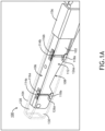
- a vehicle seat armrest assembly according to the present disclosure is indicated at reference numeral 100 and includes an armrest 102 and an arm pad 104 which is repositionable relative to the armrest 102.
- the armrest 102 may be configured for attachment at one end to a vehicle seat element such as a seat frame or backrest, and may be pivotably attached to the seat element for rotational movement between a stowed position in which the armrest is generally vertical and a deployed position in which the armrest is generally horizontal.
- the armrest may stow in a recess formed in the backrest.
- a single armrest assembly 100 is described herein and shown implemented as a left armrest, it is envisioned and intended that a vehicle seat may include a right armrest, or like left and right armrest assemblies symmetrically arranged on opposing sides of the vehicle seat.
- the armrest 102 is an elongate structural member constructed from one or more parts generally forming an armrest top 106, armrest bottom 108, armrest inboard side 110, and armrest outboard side 112.
- the term "inboard side” refers to the armrest side facing the vehicle seat and the term “outboard side” refers to the armrest side facing away from the vehicle seat, for instance facing a console positioned alongside the vehicle seat in an aircraft cockpit.
- Each of the first and second guide tracks 114a, 114b is linear and extends substantially the height of the armrest 102.
- each of the first and second guide tracks 114a, 114b may be T-shaped.
- First and second guide keepers 116a, 116b are positioned at the top of the respective first and second guide tracks 114a, 114b and function to maintain respective first and second guides 118a, 118b in their respective track and provide a contact stop for the guides.
- Each of the first and second guide keepers 116a, 116b may be constructed as a plate which secures to the armrest top 106 using one or more fasteners 120, for instance externally threaded screws received in internally threaded openings in the armrest top 106.
- each of the first and second guide keepers 116a, 116b has a notch which aligns with its guide track to allow its contained guide to rotate approximately 90 degrees upon contacting the guide keeper in order to transition the arm pad 104 from the first position to the second position or vice versa as discussed further below.
- each guide 118a, 118b interacts with its respective guide track and movably couples the arm pad 104 to the armrest 102.
- each guide 118a, 118b has a first end 122a, 122b configured to attach to the arm pad 104, for instance to the inner face of the arm pad, a second end 124a, 124b forming a bar slidable along the length of its respective guide track 114a, 114b, and a middle portion 126a, 126b which extends through the face of the armrest outboard side 112.
- Each guide 118a, 118b is configured to translate vertically along the length of its respective slot, and upon contacting its guide keeper 116a, 116b at the upper extent of travel, rotate approximately 90 degrees within its guide track to rotate the arm pad 104 to reposition the arm pad relative to the armrest 102.
- the arm pad 104 is generally elongate and includes contiguous first and second sides 128, 130 forming an angle of approximately 90 degrees.
- the arm pad 104 may further include a front end 132 contiguous with and perpendicular to each of the first side 128 and the second side 130.
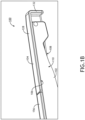
- the first and second sides 128, 130 have equal lengths but different widths such that the armrest surface area can be changed by selectively positioning the first side 128 atop the armrest to provide a first arm pad position (e.g., see FIG. 2A ), or by positioning the second side 130 atop the armrest to provide a second arm pad position (e.g., see FIG. 2E ).
- the first arm pad position corresponds to a stowed arm pad condition and the second arm pad position corresponds to a deployed arm pad condition.
- both arm pad positions may correspond to deployed arm pad conditions wherein the second arm pad position provides a wider, and therefore more ergonomic armrest, as compared to the first arm pad position.
- the width of the first side 128 may be approximately 1 inch or 2.5 cm, and the width of the second side may be approximately 2 inches or 5 cm. Other width dimensions and ratios are possible and envisioned depending on available space, preference, etc.
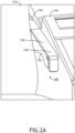
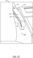
- the armrest assembly 100 is shown deployed into the space between a vehicle seat 134 and a console 136, for instance a pilot seat and an outboard console positioned in an aircraft cockpit.
- the arm pad 104 is shown in the first position in which the arm pad first side 128 is positioned on the armrest top 106 and horizontal, and the arm pad second side 130 is positioned alongside the armrest outboard side 112, in close proximity thereto, and vertical. In the first arm pad position, the bottom surface of the first side 128 may seat directly on the armrest top 106 to provide surface contact support for the arm pad 104.
- the arm pad 104 includes a rigid structural base layer 138 (e.g., metal), a cushion layer 140 positioned atop the rigid structural base layer 138, and a wrapping layer 142 covering the cushion layer 140 (e.g., leather or fabric).
- a rigid structural base layer 138 e.g., metal
- a cushion layer 140 positioned atop the rigid structural base layer 138
- a wrapping layer 142 covering the cushion layer 140 (e.g., leather or fabric).
- the guide 118a may attach to the rigid structural base layer 138 of the second side 130 proximate the lateral edge of the second side apart from the first side to allow sufficient vertical travel of the arm pad in order to reposition the arm pad first and second sides as discussed further below.
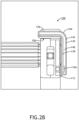
- the arm pad 104 is shown in a transitional or intermediate position between the first position ( FIGS. 2A and 2B ) and the second position ( FIGS. 2E and 2F ).
- the arm pad 104 translates vertically upward, for instance by manual lifting, from the first position to the transitional position.
- the transitional position may correspond to a change from translation motion to rotational motion or vice versa.
- the arm pad 104 is lifted until the guides 118a reach their stopping point upon contact with their respective guide keeper 116a.
- the arm pad 104 resides at a vertical position in which the second side 130 is substantially above and therefore clear of the armrest outboard side 112 such that the arm pad 104 can be rotated approximately 90 degrees to reposition the arm pad 104 relative to the armrest 102.
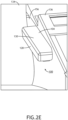
- arm pad 104 rotation continues until the second side 130 comes into surface contact with the armrest top 106.
- the second side 130 resides horizontally atop the armrest 102 and the first side 128 is positioned alongside the armrest inboard side 110 in spaced apart relation thereto, and vertical.
- FIG. 2F and FIG. 2B it can be seen that the spacing between the vertically positioned first arm pad side 128 and the armrest inboard side 110 in FIG. 2F is greater than the spacing between the vertically positioned second side 130 and the armrest outboard side 112 in FIG. 2B as a result of the wider width of the arm pad second side 130 as compared to the arm pad first side 128.
- This width difference between the two arm pad sides provides a compact arm pad stowed condition and ergonomic deployed arm pad condition.
- the surface contact area between the arm pad second side 130 and the armrest top 106 stably supports the cantilevered arm pad position shown in FIGS. 2E and 2F .
- Movement of the arm pad 104 from the first position to the second position requires upward vertical translation arm pad motion followed by inboard rotational arm pad motion, in sequential order. Movement of the arm pad 104 from the second position to the first position requires outboard rotational arm pad motion followed by downward vertical translation arm pad motion, in sequential order. Translational and rotational motions may be combined motions as the guides 118a, 118b approach and depart their point of contact with their guide keeper 116a, 116b. Arm pad movement may be purely manual, assisted, automated, or combinations thereof.
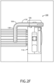
- the armrest assembly 100 can be implemented in a vehicle, for instance in an aircraft cockpit a portion of which is shown, generally including a pilot seat 134 positioned between two consoles such as an inboard console and an outboard console 136.
- the pilot seat 134 may include like right and left armrest assemblies 100 as described herein symmetrically arranged on the respective right and left sides of the seat 134.
- Each armrest assembly 100 may be attached to a rotating axle rotatably coupled to the backrest to allow each armrest assembly 100 to pivot, together or independently, relative to the backrest between a stowed condition and a deployed condition.
- each armrest assembly 100 stows generally vertically in a recess formed in the backrest, deploys by moving laterally outward with respect to the backrest, and finally rotates to a generally horizontal condition corresponding to the deployed condition. Stowing the armrest assembly 100 requires the reverse motion.
- the armrest assembly 100 may further include a fixed arm pad 156 positioned along the armrest 102 rearward of the repositionable arm pad 104. The fixed arm pad 156 is separate from the repositionable arm pad 104 and extends the total arm pad length. The fixed arm pad is immovable relative to the armrest 102 so as not to interfere with the backrest, and also completes the armrest assembly aesthetics.
- the armrest assemblies described herein are beneficial for any vehicle seat having a narrow armrest passage requiring an armrest to be thin during stowing and deployment, but can become widened when in use.
- Particular examples of vehicle seats benefitting from the armrest assemblies described herein are pilot seats positioned within tight quarters in a cockpit.
Landscapes
- Engineering & Computer Science (AREA)
- Aviation & Aerospace Engineering (AREA)
- Transportation (AREA)
- Mechanical Engineering (AREA)
- Seats For Vehicles (AREA)
Claims (12)
- Armlehnenanordnung (100) für Fahrzeugsitze, umfassend:eine Armlehne (102), die eine Oberseite (106), eine Unterseite (108), eine Innenseite (110), eine Außenseite (112) und eine beabstandete erste und zweite Führungsschiene (114a, 114b), die entlang der Außenseite vorgesehen sind, aufweist;eine erste und zweite Führung (118a, 118b), die verschiebbar in der jeweiligen ersten und zweiten Führungsschiene (114a, 114b) eingreifen; undein Armpolster (104), das an der ersten und zweiten Führung (118a, 118b) angebracht ist, wobei das Armpolster (104) eine zusammenhängende erste und zweite Seite (128, 130) aufweist,wobei das Armpolster (104) relativ zur Armlehne (102) zwischen einer ersten Position, in der die erste Seite (128) auf der Oberseite (106) der Armlehne (102) positioniert ist und die zweite Seite (130) längsseits der Außenseite (112) der Armlehne (102) positioniert ist, und einer zweiten Position, in der die erste Seite (128) längsseits der Innenseite (110) der Armlehne (102) positioniert ist und die zweite Seite (130) auf der Oberseite (106) der Armlehne (102) positioniert ist, neu positionierbar ist.
- Armlehnenanordnung (100) für Fahrzeugsitze nach Anspruch 1, wobei die zusammenhängende erste und zweite Seite (128, 130) des Armpolsters (104) einen Winkel von ungefähr 90 Grad bilden.
- Armlehnenanordnung (100) für Fahrzeugsitze nach Anspruch 1 oder 2, wobei eine Breite der zweiten Seite (130) des Armpolsters (104) größer ist als eine Breite der ersten Seite (128) des Armpolsters (104).
- Armlehnenanordnung (100) für Fahrzeugsitze nach einem der vorhergehenden Ansprüche, wobei jede der ersten und zweiten Führungsschiene (114a, 114b) an der Außenseite (112) der Armlehne (102) ausgebildet ist, linear ist und eine Länge aufweist, die ungefähr gleich der Höhe der Armlehne (102) ist.
- Armlehnenanordnung (100) für Fahrzeugsitze nach einem der vorhergehenden Ansprüche, ferner umfassend einen ersten Führungshalter (116a), der an einem oberen Ende der ersten Führungsschiene (114a) positioniert ist, um die erste Führung (118a) in der ersten Führungsschiene zu halten, und einen zweiten Führungshalter (116b), der an einem oberen Ende der zweiten Führungsschiene (114b) positioniert ist, um die zweite Führung (118b) in der zweiten Führungsschiene zu halten, wobei jeder des ersten und zweiten Führungshalters (116a, 116b) es deren jeweiliger gehaltener erster und zweiter Führung ermöglicht, sich innerhalb deren jeweiliger erster und zweiter Führungsschiene zu drehen, wenn sie am oberen Ende deren jeweiliger erster und zweiter Führungsschiene (114a, 114b) positioniert sind.
- Armlehnenanordnung (100) für Fahrzeugsitze nach einem der vorhergehenden Ansprüche, wobei;jede der ersten und zweiten Führung (118a, 118b) ein erstes Ende, das an einer Innenfläche der zweiten Seite des Armpolsters (104) angebracht ist, ein zweites Ende, das eine Stange umfasst, die entlang einer Länge der jeweiligen ersten und zweiten Führungsschiene (114a, 114b) verschiebbar ist, und einen mittleren Abschnitt umfasst, der durch eine Fläche der Außenseite der Armlehne (102) erstreckt;jede der ersten und zweiten Führung (118a, 118b) entlang einer Länge deren jeweiliger erster und zweiter Führungsschiene (114a, 114b) translatierbar ist; undjede der ersten und zweiten Führung (118a, 118b) innerhalb deren jeweiliger erster und zweiter Führungsschiene (114a, 114b) drehbar ist, wenn sie an einem oberen Ende deren jeweiliger erster und zweiter Führungsschiene positioniert sind.
- Armlehnenanordnung (100) für Fahrzeugsitze nach einem der vorhergehenden Ansprüche, wobei:eine Bewegung des Armpolsters (104) von der ersten Position in die zweite Position eine vertikale Translation des Armpolsters, gefolgt von einer Rotation in sequenzieller Reihenfolge erfordert; undeine Bewegung des Armpolsters (104) von der zweiten Position in die erste Position eine Rotation des Armpolsters, gefolgt von einer vertikalen Translation in sequenzieller Reihenfolge erfordert.
- Armlehnenanordnung (100) für Fahrzeugsitze nach einem der vorhergehenden Ansprüche, wobei die zusammenhängende erste und zweite Seite (128, 130) des Armpolsters (104) einstückig ausgebildet sind und wobei das Armpolster (104) eine starre konstruktive Basisschicht, eine über der starren konstruktiven Basisschicht positionierte Polsterschicht und eine die Polsterschicht bedeckende Umhüllungsschicht umfasst.
- Armlehnenanordnung (100) für Fahrzeugsitze nach einem der vorhergehenden Ansprüche, ferner umfassend ein fixiertes Polster (156), das getrennt von dem Armpolster (104) an der Armlehne (102) angebracht ist, wobei das fixierte Polster (156) hinter dem Armpolster (104) entlang einer Länge der Armlehne (102) positioniert ist.
- Luftfahrzeugcockpitkonfiguration, umfassend:eine Konsole (136); undeinen Pilotensitz (134), der an einer Seite der Konsole positioniert ist, wobei der Pilotensitz eine Rückenlehne und die Armlehnenanordnung (100) für Fahrzeuge nach Anspruch 1 umfasst, wobei die Armlehnenanordnung für Fahrzeuge zwischen einem verstauten Zustand längsseits der Rückenlehne und einem ausgeklappten Zustand in einem zwischen dem Pilotensitz und der Konsole bereitgestellten Raum schwenkbar ist.
- Luftfahrzeugcockpitkonfiguration nach Anspruch 10, wobei:die zusammenhängende erste und zweite Seite (128, 130) des Armpolsters (104) einen Winkel von ungefähr 90 Grad bilden;die zusammenhängende erste und zweite Seite (128, 130) des Armpolsters (104) ausgebildet sind; unddas Armpolster (104) eine starre konstruktive Basisschicht, eine über der starren konstruktiven Basisschicht positionierte Polsterschicht und eine die Polsterschicht bedeckende Umhüllungsschicht umfasst.
- Luftfahrzeugcockpitkonfiguration nach einem der Ansprüche 10 oder 11, wobei:die erste Seite des Armpolsters (104) horizontal ist, die zweite Seite des Armpolsters (104) vertikal ist und die erste Seite des Armpolsters (104) auf der Oberseite der Armlehne (102) ruht, wenn sich das Armpolster (104) in der ersten Position befindet;die erste Seite des Armpolsters (104) vertikal ist, die zweite Seite des Armpolsters (104) horizontal ist und die zweite Seite des Armpolsters (104) auf der Oberseite der Armlehne (102) ruht, wenn sich das Armpolster (104) in der zweiten Position befindet;eine Bewegung des Armpolsters (104) von der ersten Position in die zweite Position eine vertikale Translation des Armpolsters, gefolgt von einer Rotation in sequenzieller Reihenfolge erfordert; undeine Bewegung des Armpolsters (104) von der zweiten Position in die erste Position eine Rotation des Armpolsters, gefolgt von einer vertikalen Translation in sequenzieller Reihenfolge erfordert.
Applications Claiming Priority (1)
| Application Number | Priority Date | Filing Date | Title |
|---|---|---|---|
| US17/135,633 US11465751B2 (en) | 2020-12-28 | 2020-12-28 | Vehicle seat armrest assembly with repositionable arm pad |
Publications (2)
| Publication Number | Publication Date |
|---|---|
| EP4019402A1 EP4019402A1 (de) | 2022-06-29 |
| EP4019402B1 true EP4019402B1 (de) | 2024-08-07 |
Family
ID=79165011
Family Applications (1)
| Application Number | Title | Priority Date | Filing Date |
|---|---|---|---|
| EP21217546.7A Active EP4019402B1 (de) | 2020-12-28 | 2021-12-23 | Armlehnenanordnung für fahrzeugsitze mit neu positionierbarem armpolster |
Country Status (2)
| Country | Link |
|---|---|
| US (1) | US11465751B2 (de) |
| EP (1) | EP4019402B1 (de) |
Families Citing this family (1)
| Publication number | Priority date | Publication date | Assignee | Title |
|---|---|---|---|---|
| FR3127452B1 (fr) * | 2021-09-30 | 2024-01-12 | Faurecia Interieur Ind | Ensemble pour un intérieur de véhicule comprenant au moins un accoudoir et intérieur de véhicule comprenant un tel ensemble |
Citations (1)
| Publication number | Priority date | Publication date | Assignee | Title |
|---|---|---|---|---|
| KR20120096116A (ko) * | 2011-02-22 | 2012-08-30 | 한일이화주식회사 | 자동차용 암레스트의 너비 조절장치 |
Family Cites Families (20)
| Publication number | Priority date | Publication date | Assignee | Title |
|---|---|---|---|---|
| US3926473A (en) | 1974-12-23 | 1975-12-16 | Universal Oil Prod Co | Adjustable type of armrest unit |
| US4938439A (en) | 1988-07-21 | 1990-07-03 | Hollis Fried | Automobile armrest/tray accessory |
| US5104191A (en) | 1991-02-28 | 1992-04-14 | Hoover Universal, Inc. | Articulated torsion arm rest for a vehicle seat assembly |
| JP4465322B2 (ja) | 2006-01-19 | 2010-05-19 | 下西技研工業株式会社 | アームレスト |
| US20090315381A1 (en) * | 2008-06-18 | 2009-12-24 | Adam Longnecker | Airplane auxiliary armrest |
| EP2698276B1 (de) | 2012-08-16 | 2015-05-27 | Airbus (S.A.S.) | Armstützenanordnung |
| CN203637835U (zh) | 2013-12-04 | 2014-06-11 | 上海坦达轨道车辆座椅系统有限公司 | 一种座椅扶手桌板 |
| US20160101867A1 (en) * | 2014-10-13 | 2016-04-14 | Gulfstream Aerospace Corporation | Aircrew seat |
| GB2552393A (en) | 2016-06-27 | 2018-01-24 | Liq Meng Corp | Armrest table |
| US10486568B2 (en) * | 2017-06-14 | 2019-11-26 | Gulfstream Aerospace Corporation | Seat assemblies including an armrest with an armrest lid and a hinge arrangement |
| US10882427B2 (en) * | 2017-09-27 | 2021-01-05 | Gulfstream Aerospace Corporation | Seat assembly including an armrest sub-assembly and method for fabricating the same |
| CN109591838A (zh) | 2017-09-30 | 2019-04-09 | 丽盟有限公司 | 扶手桌 |
| KR101925112B1 (ko) | 2018-05-16 | 2018-12-04 | 한국항공우주산업주식회사 | 전투기용 암레스트 |
| CN108501783A (zh) | 2018-05-21 | 2018-09-07 | 大连理工大学 | 可折叠的座椅扶手 |
| CN209202507U (zh) | 2018-08-13 | 2019-08-06 | 浙江川洋家私有限公司 | 一种可调节扶手宽度的布艺沙发 |
| EP3626524B1 (de) * | 2018-09-21 | 2021-11-10 | Volvo Car Corporation | Armlehne und sitzanordnung für ein fahrzeug |
| CN110171337A (zh) | 2019-05-16 | 2019-08-27 | 肇庆学院 | 一种可变换宽度的多功能中央扶手 |
| CN110884401B (zh) | 2019-12-11 | 2022-01-21 | 怡石泰克汽车配件(武汉)有限公司 | 一种可变换宽度的多功能中央扶手 |
| KR102151953B1 (ko) | 2020-02-04 | 2020-09-04 | 한국철도공사 | 공용좌석팔걸이 |
| US11597522B2 (en) * | 2020-04-24 | 2023-03-07 | B/E Aerospace, Inc. | Vertically stowed padded tray table for passenger seat |
-
2020
- 2020-12-28 US US17/135,633 patent/US11465751B2/en active Active
-
2021
- 2021-12-23 EP EP21217546.7A patent/EP4019402B1/de active Active
Patent Citations (1)
| Publication number | Priority date | Publication date | Assignee | Title |
|---|---|---|---|---|
| KR20120096116A (ko) * | 2011-02-22 | 2012-08-30 | 한일이화주식회사 | 자동차용 암레스트의 너비 조절장치 |
Also Published As
| Publication number | Publication date |
|---|---|
| EP4019402A1 (de) | 2022-06-29 |
| US20220204166A1 (en) | 2022-06-30 |
| US11465751B2 (en) | 2022-10-11 |
Similar Documents
| Publication | Publication Date | Title |
|---|---|---|
| US6276635B1 (en) | Seat | |
| US6234553B1 (en) | Flexible seat system | |
| US9566888B2 (en) | Vehicle seat having extendable bolsters and thigh supports | |
| US5290092A (en) | Stowaway armrest | |
| US7500721B2 (en) | Seat headrest | |
| US20090058154A1 (en) | Vehicle seat assembly | |
| EP3702282B1 (de) | In mehreren positionen verstellbare kopfstützenanordnung | |
| US20150165935A1 (en) | Pivoting and reclining vehicle seating assembly | |
| US6685269B1 (en) | Vehicle seat assembly | |
| US9545886B2 (en) | Cargo tray assembly for a vehicle | |
| EP3728035B1 (de) | Tischgerät | |
| EP3393906B1 (de) | Passagiersitz mit verschiebbarem sitzelement | |
| US10882427B2 (en) | Seat assembly including an armrest sub-assembly and method for fabricating the same | |
| CA3063972A1 (en) | Deployable infill assembly and passenger seat construction | |
| EP3974317B1 (de) | Ausklappbare armlehne mit klinken- und ratschenhöheneinstellmechanismus | |
| EP4019402B1 (de) | Armlehnenanordnung für fahrzeugsitze mit neu positionierbarem armpolster | |
| CN110114242B (zh) | 包括可调节头枕的扶手椅 | |
| US12049320B2 (en) | Passenger seating assembly with swinging seatpan for increased passenger egress space | |
| EP4474275A2 (de) | Konfigurierbare mehrklassige fahrgastsitzanordnung | |
| EP4015386B1 (de) | Flugbegleitersitz mit höhenverstellbarer sitzschale | |
| EP1938714A1 (de) | Armlehne und fahrzeugsitz mit armlehne | |
| CN113696799A (zh) | 横向平移座椅台座 | |
| US7255395B2 (en) | Seat assembly with movable inner seat back | |
| US12145732B2 (en) | Vehicle seating rows for increasing cross aisle space | |
| US20220194593A1 (en) | Cabin attendant seat with height adjustable seat pan |
Legal Events
| Date | Code | Title | Description |
|---|---|---|---|
| PUAI | Public reference made under article 153(3) epc to a published international application that has entered the european phase |
Free format text: ORIGINAL CODE: 0009012 |
|
| STAA | Information on the status of an ep patent application or granted ep patent |
Free format text: STATUS: THE APPLICATION HAS BEEN PUBLISHED |
|
| AK | Designated contracting states |
Kind code of ref document: A1 Designated state(s): AL AT BE BG CH CY CZ DE DK EE ES FI FR GB GR HR HU IE IS IT LI LT LU LV MC MK MT NL NO PL PT RO RS SE SI SK SM TR |
|
| STAA | Information on the status of an ep patent application or granted ep patent |
Free format text: STATUS: REQUEST FOR EXAMINATION WAS MADE |
|
| 17P | Request for examination filed |
Effective date: 20221228 |
|
| RBV | Designated contracting states (corrected) |
Designated state(s): AL AT BE BG CH CY CZ DE DK EE ES FI FR GB GR HR HU IE IS IT LI LT LU LV MC MK MT NL NO PL PT RO RS SE SI SK SM TR |
|
| P01 | Opt-out of the competence of the unified patent court (upc) registered |
Effective date: 20230922 |
|
| GRAP | Despatch of communication of intention to grant a patent |
Free format text: ORIGINAL CODE: EPIDOSNIGR1 |
|
| STAA | Information on the status of an ep patent application or granted ep patent |
Free format text: STATUS: GRANT OF PATENT IS INTENDED |
|
| INTG | Intention to grant announced |
Effective date: 20240307 |
|
| RIN1 | Information on inventor provided before grant (corrected) |
Inventor name: ROSS, DAVID A. Inventor name: HOOVER, DOUGLAS |
|
| GRAS | Grant fee paid |
Free format text: ORIGINAL CODE: EPIDOSNIGR3 |
|
| GRAA | (expected) grant |
Free format text: ORIGINAL CODE: 0009210 |
|
| STAA | Information on the status of an ep patent application or granted ep patent |
Free format text: STATUS: THE PATENT HAS BEEN GRANTED |
|
| AK | Designated contracting states |
Kind code of ref document: B1 Designated state(s): AL AT BE BG CH CY CZ DE DK EE ES FI FR GB GR HR HU IE IS IT LI LT LU LV MC MK MT NL NO PL PT RO RS SE SI SK SM TR |
|
| REG | Reference to a national code |
Ref country code: GB Ref legal event code: FG4D |
|
| REG | Reference to a national code |
Ref country code: CH Ref legal event code: EP |
|
| REG | Reference to a national code |
Ref country code: IE Ref legal event code: FG4D |
|
| REG | Reference to a national code |
Ref country code: DE Ref legal event code: R096 Ref document number: 602021016777 Country of ref document: DE |
|
| REG | Reference to a national code |
Ref country code: LT Ref legal event code: MG9D |
|
| REG | Reference to a national code |
Ref country code: NL Ref legal event code: MP Effective date: 20240807 |
|
| PG25 | Lapsed in a contracting state [announced via postgrant information from national office to epo] |
Ref country code: NO Free format text: LAPSE BECAUSE OF FAILURE TO SUBMIT A TRANSLATION OF THE DESCRIPTION OR TO PAY THE FEE WITHIN THE PRESCRIBED TIME-LIMIT Effective date: 20241107 |
|
| REG | Reference to a national code |
Ref country code: AT Ref legal event code: MK05 Ref document number: 1710658 Country of ref document: AT Kind code of ref document: T Effective date: 20240807 |
|
| PG25 | Lapsed in a contracting state [announced via postgrant information from national office to epo] |
Ref country code: GR Free format text: LAPSE BECAUSE OF FAILURE TO SUBMIT A TRANSLATION OF THE DESCRIPTION OR TO PAY THE FEE WITHIN THE PRESCRIBED TIME-LIMIT Effective date: 20241108 Ref country code: NL Free format text: LAPSE BECAUSE OF FAILURE TO SUBMIT A TRANSLATION OF THE DESCRIPTION OR TO PAY THE FEE WITHIN THE PRESCRIBED TIME-LIMIT Effective date: 20240807 Ref country code: PL Free format text: LAPSE BECAUSE OF FAILURE TO SUBMIT A TRANSLATION OF THE DESCRIPTION OR TO PAY THE FEE WITHIN THE PRESCRIBED TIME-LIMIT Effective date: 20240807 Ref country code: PT Free format text: LAPSE BECAUSE OF FAILURE TO SUBMIT A TRANSLATION OF THE DESCRIPTION OR TO PAY THE FEE WITHIN THE PRESCRIBED TIME-LIMIT Effective date: 20241209 Ref country code: FI Free format text: LAPSE BECAUSE OF FAILURE TO SUBMIT A TRANSLATION OF THE DESCRIPTION OR TO PAY THE FEE WITHIN THE PRESCRIBED TIME-LIMIT Effective date: 20240807 |
|
| PG25 | Lapsed in a contracting state [announced via postgrant information from national office to epo] |
Ref country code: BG Free format text: LAPSE BECAUSE OF FAILURE TO SUBMIT A TRANSLATION OF THE DESCRIPTION OR TO PAY THE FEE WITHIN THE PRESCRIBED TIME-LIMIT Effective date: 20240807 |
|
| PG25 | Lapsed in a contracting state [announced via postgrant information from national office to epo] |
Ref country code: LV Free format text: LAPSE BECAUSE OF FAILURE TO SUBMIT A TRANSLATION OF THE DESCRIPTION OR TO PAY THE FEE WITHIN THE PRESCRIBED TIME-LIMIT Effective date: 20240807 |
|
| PG25 | Lapsed in a contracting state [announced via postgrant information from national office to epo] |
Ref country code: AT Free format text: LAPSE BECAUSE OF FAILURE TO SUBMIT A TRANSLATION OF THE DESCRIPTION OR TO PAY THE FEE WITHIN THE PRESCRIBED TIME-LIMIT Effective date: 20240807 Ref country code: IS Free format text: LAPSE BECAUSE OF FAILURE TO SUBMIT A TRANSLATION OF THE DESCRIPTION OR TO PAY THE FEE WITHIN THE PRESCRIBED TIME-LIMIT Effective date: 20241207 |
|
| PG25 | Lapsed in a contracting state [announced via postgrant information from national office to epo] |
Ref country code: HR Free format text: LAPSE BECAUSE OF FAILURE TO SUBMIT A TRANSLATION OF THE DESCRIPTION OR TO PAY THE FEE WITHIN THE PRESCRIBED TIME-LIMIT Effective date: 20240807 |
|
| PG25 | Lapsed in a contracting state [announced via postgrant information from national office to epo] |
Ref country code: ES Free format text: LAPSE BECAUSE OF FAILURE TO SUBMIT A TRANSLATION OF THE DESCRIPTION OR TO PAY THE FEE WITHIN THE PRESCRIBED TIME-LIMIT Effective date: 20240807 Ref country code: RS Free format text: LAPSE BECAUSE OF FAILURE TO SUBMIT A TRANSLATION OF THE DESCRIPTION OR TO PAY THE FEE WITHIN THE PRESCRIBED TIME-LIMIT Effective date: 20241107 |
|
| PG25 | Lapsed in a contracting state [announced via postgrant information from national office to epo] |
Ref country code: RS Free format text: LAPSE BECAUSE OF FAILURE TO SUBMIT A TRANSLATION OF THE DESCRIPTION OR TO PAY THE FEE WITHIN THE PRESCRIBED TIME-LIMIT Effective date: 20241107 Ref country code: PT Free format text: LAPSE BECAUSE OF FAILURE TO SUBMIT A TRANSLATION OF THE DESCRIPTION OR TO PAY THE FEE WITHIN THE PRESCRIBED TIME-LIMIT Effective date: 20241209 Ref country code: PL Free format text: LAPSE BECAUSE OF FAILURE TO SUBMIT A TRANSLATION OF THE DESCRIPTION OR TO PAY THE FEE WITHIN THE PRESCRIBED TIME-LIMIT Effective date: 20240807 Ref country code: NO Free format text: LAPSE BECAUSE OF FAILURE TO SUBMIT A TRANSLATION OF THE DESCRIPTION OR TO PAY THE FEE WITHIN THE PRESCRIBED TIME-LIMIT Effective date: 20241107 Ref country code: NL Free format text: LAPSE BECAUSE OF FAILURE TO SUBMIT A TRANSLATION OF THE DESCRIPTION OR TO PAY THE FEE WITHIN THE PRESCRIBED TIME-LIMIT Effective date: 20240807 Ref country code: LV Free format text: LAPSE BECAUSE OF FAILURE TO SUBMIT A TRANSLATION OF THE DESCRIPTION OR TO PAY THE FEE WITHIN THE PRESCRIBED TIME-LIMIT Effective date: 20240807 Ref country code: IS Free format text: LAPSE BECAUSE OF FAILURE TO SUBMIT A TRANSLATION OF THE DESCRIPTION OR TO PAY THE FEE WITHIN THE PRESCRIBED TIME-LIMIT Effective date: 20241207 Ref country code: HR Free format text: LAPSE BECAUSE OF FAILURE TO SUBMIT A TRANSLATION OF THE DESCRIPTION OR TO PAY THE FEE WITHIN THE PRESCRIBED TIME-LIMIT Effective date: 20240807 Ref country code: GR Free format text: LAPSE BECAUSE OF FAILURE TO SUBMIT A TRANSLATION OF THE DESCRIPTION OR TO PAY THE FEE WITHIN THE PRESCRIBED TIME-LIMIT Effective date: 20241108 Ref country code: FI Free format text: LAPSE BECAUSE OF FAILURE TO SUBMIT A TRANSLATION OF THE DESCRIPTION OR TO PAY THE FEE WITHIN THE PRESCRIBED TIME-LIMIT Effective date: 20240807 Ref country code: ES Free format text: LAPSE BECAUSE OF FAILURE TO SUBMIT A TRANSLATION OF THE DESCRIPTION OR TO PAY THE FEE WITHIN THE PRESCRIBED TIME-LIMIT Effective date: 20240807 Ref country code: BG Free format text: LAPSE BECAUSE OF FAILURE TO SUBMIT A TRANSLATION OF THE DESCRIPTION OR TO PAY THE FEE WITHIN THE PRESCRIBED TIME-LIMIT Effective date: 20240807 Ref country code: AT Free format text: LAPSE BECAUSE OF FAILURE TO SUBMIT A TRANSLATION OF THE DESCRIPTION OR TO PAY THE FEE WITHIN THE PRESCRIBED TIME-LIMIT Effective date: 20240807 |
|
| PG25 | Lapsed in a contracting state [announced via postgrant information from national office to epo] |
Ref country code: SM Free format text: LAPSE BECAUSE OF FAILURE TO SUBMIT A TRANSLATION OF THE DESCRIPTION OR TO PAY THE FEE WITHIN THE PRESCRIBED TIME-LIMIT Effective date: 20240807 Ref country code: DK Free format text: LAPSE BECAUSE OF FAILURE TO SUBMIT A TRANSLATION OF THE DESCRIPTION OR TO PAY THE FEE WITHIN THE PRESCRIBED TIME-LIMIT Effective date: 20240807 |
|
| PG25 | Lapsed in a contracting state [announced via postgrant information from national office to epo] |
Ref country code: EE Free format text: LAPSE BECAUSE OF FAILURE TO SUBMIT A TRANSLATION OF THE DESCRIPTION OR TO PAY THE FEE WITHIN THE PRESCRIBED TIME-LIMIT Effective date: 20240807 |
|
| PG25 | Lapsed in a contracting state [announced via postgrant information from national office to epo] |
Ref country code: CZ Free format text: LAPSE BECAUSE OF FAILURE TO SUBMIT A TRANSLATION OF THE DESCRIPTION OR TO PAY THE FEE WITHIN THE PRESCRIBED TIME-LIMIT Effective date: 20240807 |
|
| PG25 | Lapsed in a contracting state [announced via postgrant information from national office to epo] |
Ref country code: SK Free format text: LAPSE BECAUSE OF FAILURE TO SUBMIT A TRANSLATION OF THE DESCRIPTION OR TO PAY THE FEE WITHIN THE PRESCRIBED TIME-LIMIT Effective date: 20240807 |
|
| REG | Reference to a national code |
Ref country code: DE Ref legal event code: R097 Ref document number: 602021016777 Country of ref document: DE |
|
| PLBE | No opposition filed within time limit |
Free format text: ORIGINAL CODE: 0009261 |
|
| STAA | Information on the status of an ep patent application or granted ep patent |
Free format text: STATUS: NO OPPOSITION FILED WITHIN TIME LIMIT |
|
| PG25 | Lapsed in a contracting state [announced via postgrant information from national office to epo] |
Ref country code: MC Free format text: LAPSE BECAUSE OF FAILURE TO SUBMIT A TRANSLATION OF THE DESCRIPTION OR TO PAY THE FEE WITHIN THE PRESCRIBED TIME-LIMIT Effective date: 20240807 |
|
| 26N | No opposition filed |
Effective date: 20250508 |
|
| REG | Reference to a national code |
Ref country code: CH Ref legal event code: PL |
|
| PG25 | Lapsed in a contracting state [announced via postgrant information from national office to epo] |
Ref country code: LU Free format text: LAPSE BECAUSE OF NON-PAYMENT OF DUE FEES Effective date: 20241223 |
|
| PG25 | Lapsed in a contracting state [announced via postgrant information from national office to epo] |
Ref country code: SE Free format text: LAPSE BECAUSE OF FAILURE TO SUBMIT A TRANSLATION OF THE DESCRIPTION OR TO PAY THE FEE WITHIN THE PRESCRIBED TIME-LIMIT Effective date: 20240807 |
|
| REG | Reference to a national code |
Ref country code: BE Ref legal event code: MM Effective date: 20241231 |
|
| PG25 | Lapsed in a contracting state [announced via postgrant information from national office to epo] |
Ref country code: BE Free format text: LAPSE BECAUSE OF NON-PAYMENT OF DUE FEES Effective date: 20241231 |
|
| PG25 | Lapsed in a contracting state [announced via postgrant information from national office to epo] |
Ref country code: CH Free format text: LAPSE BECAUSE OF NON-PAYMENT OF DUE FEES Effective date: 20241231 |
|
| PG25 | Lapsed in a contracting state [announced via postgrant information from national office to epo] |
Ref country code: IE Free format text: LAPSE BECAUSE OF NON-PAYMENT OF DUE FEES Effective date: 20241223 |
|
| PG25 | Lapsed in a contracting state [announced via postgrant information from national office to epo] |
Ref country code: RO Free format text: LAPSE BECAUSE OF FAILURE TO SUBMIT A TRANSLATION OF THE DESCRIPTION OR TO PAY THE FEE WITHIN THE PRESCRIBED TIME-LIMIT Effective date: 20240807 |
|
| PGFP | Annual fee paid to national office [announced via postgrant information from national office to epo] |
Ref country code: DE Payment date: 20251126 Year of fee payment: 5 |
|
| PGFP | Annual fee paid to national office [announced via postgrant information from national office to epo] |
Ref country code: GB Payment date: 20251120 Year of fee payment: 5 |
|
| PGFP | Annual fee paid to national office [announced via postgrant information from national office to epo] |
Ref country code: FR Payment date: 20251120 Year of fee payment: 5 |
|
| PG25 | Lapsed in a contracting state [announced via postgrant information from national office to epo] |
Ref country code: IT Free format text: LAPSE BECAUSE OF FAILURE TO SUBMIT A TRANSLATION OF THE DESCRIPTION OR TO PAY THE FEE WITHIN THE PRESCRIBED TIME-LIMIT Effective date: 20240807 |