EP3974317B1 - Ausklappbare armlehne mit klinken- und ratschenhöheneinstellmechanismus - Google Patents
Ausklappbare armlehne mit klinken- und ratschenhöheneinstellmechanismus Download PDFInfo
- Publication number
- EP3974317B1 EP3974317B1 EP21198976.9A EP21198976A EP3974317B1 EP 3974317 B1 EP3974317 B1 EP 3974317B1 EP 21198976 A EP21198976 A EP 21198976A EP 3974317 B1 EP3974317 B1 EP 3974317B1
- Authority
- EP
- European Patent Office
- Prior art keywords
- armrest
- rack
- pawl
- detents
- lever
- Prior art date
- Legal status (The legal status is an assumption and is not a legal conclusion. Google has not performed a legal analysis and makes no representation as to the accuracy of the status listed.)
- Active
Links
Images


Classifications
-
- B—PERFORMING OPERATIONS; TRANSPORTING
- B64—AIRCRAFT; AVIATION; COSMONAUTICS
- B64D—EQUIPMENT FOR FITTING IN OR TO AIRCRAFT; FLIGHT SUITS; PARACHUTES; ARRANGEMENT OR MOUNTING OF POWER PLANTS OR PROPULSION TRANSMISSIONS IN AIRCRAFT
- B64D11/00—Passenger or crew accommodation; Flight-deck installations not otherwise provided for
- B64D11/06—Arrangements of seats, or adaptations or details specially adapted for aircraft seats
- B64D11/0639—Arrangements of seats, or adaptations or details specially adapted for aircraft seats with features for adjustment or converting of seats
- B64D11/0644—Adjustable arm rests
-
- B—PERFORMING OPERATIONS; TRANSPORTING
- B64—AIRCRAFT; AVIATION; COSMONAUTICS
- B64D—EQUIPMENT FOR FITTING IN OR TO AIRCRAFT; FLIGHT SUITS; PARACHUTES; ARRANGEMENT OR MOUNTING OF POWER PLANTS OR PROPULSION TRANSMISSIONS IN AIRCRAFT
- B64D11/00—Passenger or crew accommodation; Flight-deck installations not otherwise provided for
- B64D11/06—Arrangements of seats, or adaptations or details specially adapted for aircraft seats
- B64D11/0689—Arrangements of seats, or adaptations or details specially adapted for aircraft seats specially adapted for pilots
Definitions
- the present disclosure relates generally to a deployable and adjustable armrest assembly, and more particularly, to a deployable armrest including height adjustment capability via a pawl and ratchet mechanism advantageous for use in close quarters, for instance with a pilot seat in an aircraft flight deck.
- Aircraft flight decks are typically configured around pilot seats and aircraft controls. Flight decks that include two pilot seats, positioned side-by-side, typically include a center console. Flight decks that include one or more pilot seats also typically include outboard consoles, each positioned to one side of its respective pilot seat. In most flight deck configurations, each console is typically positioned in close proximity to its respective seat considering the relatively narrow width of a flight deck and tapering sidewalls.
- Pilot seats may include adjustable elements for improving seat comfort.
- One such element includes deployable armrests.
- each armrest is configured to stow in a recess formed in the seat back and deploy to a substantially horizontal use position.
- the armrest is coupled to a sliding axle about which the armrest pivots between vertical and horizontal orientations.
- the pilot is required to reach behind the seat, locate the armrest, slide the armrest away from the recess, and finally rotate the armrest downward toward horizontal. Access to the armrest and deployment can be difficult considering the stowed location of the armrest and close proximity of an adjacent console.
- the armrest requires a tilt adjustment mechanism to compensate for seat back recline motion.
- an armrest assembly including a support bracket configured to attach to a seat element, a rack receiver coupled to the support bracket, and a rack slidable relative to the rack receiver, the rack including an elongate slot formed along a longitudinal length of the rack and a plurality of detents formed along one edge of the rack, each of the plurality of detents corresponding to an armrest deployment position.
- An armrest is positioned atop the rack and space guides carried by the rack receiver are engaged in the elongate slot of the rack.
- a lever is pivotally attached to the rack receiver and a pawl carried by the lever is configured to engage in the plurality of detents, one at a time, to lock the armrest in a selected armrest deployment position.
- a biasing member is coupled between the lever and the rack receiver to bias the pawl toward an engaged position.
- the armrest is adjustable, for instance via manual lifting, between a stowed position alongside a seat bottom and one of a one of plurality of discrete armrest deployment positions.
- the plurality of detents are positioned proximate a lower end of the one edge of the rack, and none of the plurality of detents are positioned proximate an upper end of the one edge of the rack.
- each of the plurality of detents is formed by a first surface and a second surface angled relative to the first surface.
- a pawl roller is rotatably carried on a free end of the pawl and is configured to travel along and maintain engagement with the one edge of the rack as the armrest is raised.
- the support bracket and the rack receiver are integrally formed, and the rack is slidably disposed in the rack receiver.
- the armrest is configured to be raised to move the armrest from the stowed position to a first armrest deployment position, the armrest is configured to be raised from the first armrest deployment position to a second and successive armrest deployment positions, and the lever is configured to be actuated to disengage the pawl from engagement in one of the plurality of detents.
- a pivot axis of the lever is positioned forward of the one edge of the rack.
- the present disclosure provides a pilot seat assembly including a seat frame supporting a seat bottom, and an armrest assembly attached to the seat frame.
- the armrest assembly includes a support bracket attached to the seat frame, a rack receiver coupled to the support bracket, and a rack slidable relative to the rack receiver.
- the rack includes an elongate slot formed along a longitudinal length of the rack and a plurality of detents formed along one edge of the rack, each of the plurality of detents corresponding to an armrest deployment position.
- An armrest is positioned atop the rack and space guides carried by the rack receiver are engaged in the elongate slot of the rack.
- a lever is pivotally attached to the rack receiver and a pawl is carried by the lever, the pawl configured to engage in one of the plurality of detents to lock the armrest in a selected armrest deployment position.
- a biasing member coupled between the lever and the rack receiver biases the pawl toward an engaged position.
- the armrest when in the stowed positioned is laterally adjacent one side of the seat bottom such that a top surface of the armrest when in the stowed position is horizontally aligned with a top surface of the seat bottom adjacent the armrest.
- a pivot axis of the lever is positioned forward of the one edge of the rack, the plurality of detents are positioned proximate a lower end of the one edge of the rack, none of the plurality of detents are positioned proximate an upper end of the one edge of the rack, and the lever is positioned above the support bracket and below the armrest.
- the armrest is configured to be raise manually to move the armrest from the stowed position to a first armrest deployment position, the armrest is configured to be raised manually from the first armrest deployment position to a second and successive armrest deployment positions, and the lever is configured to be actuated manually to disengage the pawl engagement in one of the plurality of detents.
- any reference to “one embodiment” or “some embodiments” means that a particular element, feature, structure, or characteristic described in connection with the embodiment is included in at least one embodiment disclosed herein.
- the appearances of the phrase “in some embodiments” in various places in the specification are not necessarily all referring to the same embodiment, and embodiments may include one or more of the features expressly described or inherently present herein, or any combination or sub-combination of two or more such features, along with any other features which may not necessarily be expressly described or inherently present in the instant disclosure.
- the inventive concepts disclosed herein are directed to a deployable and height adjustable armrest assembly for use with a seat, for instance a pilot seat for rotary wing and other aircraft types. Adjustability is provided through a predetermined number of possible elevated armrest positions. In use, the armrest can be lifted to a first and subsequent raised positions, and downward force applied to a handle releases the armrest to allow the armrest to be lowered. As such, single handed operation can be used to raise the armrest for ease of use.
- FIG. 1 shows a non-limiting example of a pilot seat equipped with an armrest assembly 100 according to an embodiment of the present disclosure.
- the pilot seat 102 generally includes a seat bottom 104 supported by or atop a frame 106.
- a seat back 108 attaches to the frame 106 and/or seat bottom 104.
- the frame 106 may secure to the deck 110 via track fasteners 112 configured to attach to seat tracks 113 positioned on or in the deck 110.
- the configuration of the pilot seat 102 is not critical to the present disclosure as the armrest assembly 100 is compatible for use with different types and configurations of seats.
- the armrest assembly 100 generally includes a support bracket 114 configured for attachment to a seat element, for instance the frame 106, for example a seat spreader, supporting the seat bottom 104.
- the frame 106 may be fixed or moveable and in a preferred embodiment, the armrest assembly 100 is attachable to the frame such that the seat bottom 104 and armrest assembly 100 move together but not relative to each other.
- the support bracket 114 may be constructed from a rigid material (e.g., aluminum) and attaches to the frame by way of fasteners, welding, etc.
- a rack receiver 116 couples to the support bracket 114 and is positioned laterally adjacent one side of the seat bottom 104.
- the rack receiver 116 is an elongate tubular member having an open top and bottom through which a rack 118 is received such that portions are coextensive.
- the orientation of the rack receiver 116 determines the angle of the rack 118, which may be vertical or near vertical.
- a forward extending portion 120 of the rack receiver 116 serves as the attachment location for a lever 122 manually actuated to release the rack 118 to lower the armrest as discussed below.
- the horizontal pivot axis 124 of the lever 122 is positioned forward of the rack 118.
- the lever 122 includes a first end 126 that extends rearward and is coupled to the rack receiver 116 via a biasing mechanism 128, and a second end 130 that extends forward and forms a handle 132 for gripping the lever 122.
- the biasing mechanism 128 includes a helical spring 134 having a first end attached to the first end 126 of the lever 122, and a second end attached to the rack receiver 116 or a feature coupled to the rack receiver 116, first instance a guide as discussed below. In use, the biasing mechanism 128 biases the lever 122 toward an engaged position as discussed below.
- the lever 122 configuration shown allows for manual actuation, it is envisioned and intended that the adjustment mechanism may be electronically or otherwise controlled, for example via an actuator coupled to a pulling cable and switch.
- An armrest 136 is positioned atop the rack 118 and includes an arm pad 138 that may be cushioned and/or upholstered.
- FIG. 1 shows the fully stowed position of the armrest 136 in which the top surface of the arm pad 138 resides coplanar with the top surface of the seat bottom 104.
- the armrest 136 and the seat bottom 104 are similarly contoured such that when the armrest 136 is stowed the armrest 136 is essentially invisible, does not disrupt the styling cues of the seat, and increases the lateral space of the seat bottom 104.
- Such a configuration may allow the pilot seat 102 equipped with the armrest assembly 100 to meet minimum ergonomic seat pan requirements.
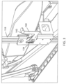
- FIG. 2 shows the rack 118 raised relative to the rack receiver 116 to position the armrest (not shown) in a predetermined deployed position for use (i.e., raised).
- the rack 118 may be raised by lifting the armrest 136 manually with one hand for ease of use.
- FIG. 2 shows the lever handle 132 tilted slightly rearward which corresponds to an engaged or locked condition of the lever 122.
- FIG. 1 shows the lever handle 132 tilted slightly forward which corresponds to a disengaged or unlocked condition of the lever 122.
- the rack 118 may or may not include a detent for locking the rack 118 in a position corresponding to the fully stowed position of the armrest.
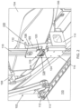
- FIG. 3 shows the lever 122 tilted forward corresponding to a disengaged or unlocked condition of the lever.
- the lever 122 may be pivoted forward manually by hand by pushing downward, or may be pivoted forward by the engagement of a pawl 140 carried by the lever 122 as the pawl 140 travels over a feature formed along a forward end of the rack 118, as discussed below.
- FIG. 3 further shows the helical spring 134 extended and therefore energized to provide the force to bias the lever 122 toward the engaged position.
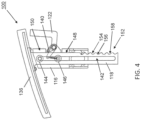
- FIG. 4 shows the armrest assembly 100 removed from a seat for clarity of the assembly.
- the rack 118 is an elongate member forming a longitudinally extending slot 142 within which spaced guides 144, 146 carried on the rack receiver 116 travel along.
- the guides 144, 146 are spaced apart such that the rack 118 tracks linearly up and down relative to the rack receiver 116 with stability and without rotating.
- the upper guide 144 may be positioned relative to the rack receiver 118 to provide a physical stop against over travel of the rack 118 downward.
- the lower guide 146 may be positioned relative to the rack receiver 118 to provide a physical stop against over travel of the rack 118 upward.
- the upper and lower guides 144, 146 may be posts having a flanged head or vertical rollers that function to guide and maintain vertical motion of the rack 118 between its fully raised and fully lowered positions.
- the pawl 140 is carried by the lever 122 and therefore moves in and out of contact with the rack 118 with the movement of the lever 122.
- FIG. 4 shows the armrest 136 in a fully stowed condition proximate to the top end of the rack receiver 116, a portion of which is removed in the drawing for clarity.
- the forward edge 148 of the rack 118 forms a bearing surface along which the pawl 140 travels and maintains engagement, at least when the lever 122 is not fully disengaged.
- the bearing surface includes an upper portion 150 and a lower portion 152.
- the upper portion 150 is linear and featureless such that the pawl 140 tracks along the linear upper portion from the fully stowed position until the first deployment position.
- the lower portion 152 forms a plurality of detents 154 each formed by a first surface 156 and a second surface 158 angled relative to the first surface 156.
- Each detent 154 serves as a 'catch' for the pawl 140 and corresponds to a raised position of the armrest 136.
- the plurality of detents 154 are arranged vertically such that each successive detent 154, from top to bottom, corresponds to a higher armrest position.
- the rack 118 includes seven detents corresponding to seven possible deployed armrest positions. In some embodiments, the lowest detent or more may or may not be functional. Any number of detents are possible, as well as the positions of the detents and spacing therebetween, depending on the number of desired discrete armrest positions.
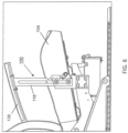
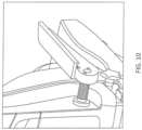
- FIG. 5 shows the pawl 140 engaged in the third detent 154 from the top, which corresponds to a third deployed position of the armrest 136.
- the pawl 140 carries a pawl roller 160 on its free for facilitating rolling engagement and smooth tracking and transition between detents.
- the free end of the pawl 140 carrying the pawl roller 160 is angled upward to engage within the detents 154 formed along the forward edge of the rack 118 each corresponding to a discrete armrest position.
- each detent is angled upward to prevent the pawl 140 from disengaging from the detent under the force of the biasing mechanism 128.
- the second surface (158 in FIG. 4 ) is angled downward such that, upon raising the armrest 136, the pawl roller 160 tracks along the second surface, tracks along the transitional portion between detents, and locates into the next lower detent.
- the handle 130 is pivoted forward, such as by pushing downward, against the force of the biasing mechanism 128 to disengage the pawl 140 from the detent to allow the armrest 136 to be lowered to another lower deployed position or to stow the armrest 136.
- single handed operation can be used to raise the armrest 136, as none of the engagement surfaces formed on the forward end of the rack 118 resist or prevent upward movement of the rack 118.
- two-handed operation can be used to lower the armrest 136 gently, with one hand operating the lever 122 and the other hand grabbing the armrest 136.
- single handed lowering is possible simply by actuating the lever 122, but may be undesirable for allowing the armrest 134 to drop uncontrollably.
- FIG. 6 shows the pawl roller 160 transitioning from the third detent, corresponding to the third armrest deployment position, to the fourth detent, corresponding armrest deployment position, by tracking over the transitional 'peak' provided between the third and fourth 'troughs.
- the pawl roller 160 tracks along the surface features thereby causing the lever 122 to pivot against the force of the biasing mechanism 128, and the action of the biasing mechanism causing the pawl roller 160 to remain engaged against and follow the formed surface features, thereby locating the pawl 140 in each successive detent.
- the armrest 136 can be raised to the desired deployment height and the pawl locates in the respective detent automatically.
- FIG. 7 shows the pawl roller 160 engaged in the fifth detent from the top corresponding to the fifth discrete armrest position.
- FIG. 8 shows the armrest assembly 100 installed on a non-limiting example of a seat and with the armrest 136 shown in the fifth detent corresponding to the fifth highest position of the armrest 136. Understandable from FIG. 8 , the first or uppermost detent positions the armrest 136 closest the seat bottom 104, and each successive lower detent positions the armrest 136 farther from the seat bottom 104. Again, the number, position and spacing of the detents is customizable to provide any number of adjustable positions and to accommodate different seat designs. As shown, the uppermost or first detent is provided spaced apart from the armrest 136, for example several centimetres (inches), such that the rack 118 is required to be raised several centimetres (inches) before reaching the first engagement.
- This configuration provides spacing between the armrest 136 and handle (removed for clarity) for comfortably locating and actuating the handle, and may correspond to the first desirable position of the deployed armrest 164.
- a shroud may serve to cover portions of the assembly for aesthetic reasons and to conceal pinch points.
- FIG. 9 shows the armrest 136 fully stowed such that the pawl roller 160 is engaged along the linear upper portion of the rack 118 and the upper guide 144 engaging the upper end of the elongate slot 142 to prevent over travel of the rack 118 downward.
- FIG. 9 further illustrates the coplanarity of the top of the armrest 136 with the top of the seat bottom 104 to increase the lateral space of the seat bottom 104.
- the seat may be equipped with left and right armrest assemblies symmetrically arranged on the respective left and right sides of the seat.
Landscapes
- Engineering & Computer Science (AREA)
- Aviation & Aerospace Engineering (AREA)
- Seats For Vehicles (AREA)
Claims (14)
- Armlehnenbaugruppe, umfassend:einen Stützbügel (114), der zur Befestigung an einem Sitzelement konfiguriert ist;eine Gestellaufnahme (116), die mit dem Stützbügel gekoppelt ist;ein Gestell (118), das relativ zu der Gestellaufnahme verschiebbar ist, wobei das Gestell einen länglichen Schlitz (142), der entlang einer Längslänge des Gestells ausgebildet ist, und eine Vielzahl von Arretierungen (154) beinhaltet, die entlang einer Kante des Gestells ausgebildet ist, wobei jede der Vielzahl von Arretierungen einer Armlehnenausklappposition entspricht;eine Armlehne (136), die oben auf dem Gestell positioniert ist;Raumführungen, die von der Gestellaufnahme getragen werden und in den länglichen Schlitz des Gestells eingreifen;einen Hebel (122), der schwenkbar an der Gestellaufnahme befestigt ist;eine Klinke (140), die von dem Hebel getragen wird, wobei die Klinke dazu konfiguriert ist, in die Vielzahl von Arretierungen einzugreifen, um die Armlehne in einer ausgewählten Armlehnenausklappposition zu verriegeln; undein Vorspannelement (128), das zwischen dem Hebel und der Gestellaufnahme gekoppelt ist und die Klinke in Richtung einer Eingriffsposition vorspannt;wobei die Armlehne im Gebrauch zwischen einer verstauten Position und einer Vielzahl von diskreten Armlehnenausklapppositionen verstellbar ist.
- Armlehnenbaugruppe nach Anspruch 1, wobei die Vielzahl von Arretierungen (154) in der Nähe eines unteren Endes der einen Kante des Gestells positioniert ist und wobei keine der Vielzahl von Arretierungen in der Nähe eines oberen Endes der einen Kante des Gestells positioniert ist.
- Armlehnenbaugruppe nach Anspruch 1, wobei jede der Vielzahl von Arretierungen durch eine erste Fläche (156) und eine zweite Fläche (158) gebildet wird, die relativ zu der ersten Fläche abgewinkelt ist.
- Armlehnenbaugruppe nach einem der vorhergehenden Ansprüche, wobei:eine Klinkenrolle (160) drehbar an einem freien Ende der Klinke getragen wird; unddie Klinkenrolle sich entlang der einen Kante des Gestells bewegt und mit dieser in Eingriff bleibt, wenn die Armlehne angehoben wird.
- Armlehnenbaugruppe nach einem der vorhergehenden Ansprüche, wobei der Stützbügel und die Gestellaufnahme einstückig ausgebildet sind.
- Armlehnenbaugruppe nach einem der vorhergehenden Ansprüche, wobei das Gestell verschiebbar in der Gestellaufnahme angeordnet ist.
- Armlehnenbaugruppe nach einem der vorhergehenden Ansprüche, wobei:die Armlehne dazu konfiguriert ist, angehoben zu werden, um die Armlehne aus der verstauten Position in eine erste Armlehnenausklappposition zu bewegen;die Armlehne dazu konfiguriert ist, von der ersten Armlehnenausklappposition in eine zweite und weitere Armlehnenausklapppositionen angehoben zu werden; undder Hebel dazu konfiguriert ist, betätigt zu werden, um die Klinke aus dem Eingriff in eine der Vielzahl von Arretierungen zu lösen.
- Armlehnenbaugruppe nach einem der vorhergehenden Ansprüche, wobei eine Schwenkachse des Hebels vor der einen Kante des Gestells angeordnet ist.
- Pilotensitzbaugruppe, umfassend:einen Sitzrahmen (106), der eine Sitzfläche stützt; undeine Armlehnenbaugruppe (100) nach einem der vorhergehenden Ansprüche, wobei der Stützbügel (114) an dem Sitzrahmen befestigt ist, wobei die Armlehnenbaugruppe umfasst:
einen Stützbügel, der an dem Sitzrahmen befestigt ist. - Pilotensitzbaugruppe nach Anspruch 9, wobei die Armlehne in der verstauten Position seitlich an eine Seite der Sitzfläche angrenzt, und wobei eine Oberseite der Armlehne in der verstauten Position horizontal mit einer Oberseite der Sitzfläche neben der Armlehne ausgerichtet ist.
- Pilotensitzbaugruppe nach Anspruch 9, wobei:eine Schwenkachse des Hebels vor der einen Kante des Gestells positioniert ist;die Vielzahl von Arretierungen in der Nähe eines unteren Endes der einen Kante des Gestells positioniert ist; undkeine der Vielzahl von Arretierungen in der Nähe eines oberen Endes der einen Kante des Gestells positioniert ist.
- Pilotensitzbaugruppe nach Anspruch 9 in Abhängigkeit von Anspruch 4, wobei:
die Klinkenrolle dazu konfiguriert ist, sich entlang der einen Kante des Gestells zu bewegen und mit dieser in Eingriff zu bleiben, wenn die Armlehne angehoben wird. - Pilotensitzbaugruppe nach Anspruch 9, wobei:die Armlehne dazu konfiguriert ist, manuell angehoben zu werden, um die Armlehne aus der verstauten Position in eine erste Armlehnenausklappposition zu bewegen;die Armlehne dazu konfiguriert ist, manuell aus der ersten Armlehnenausklappposition in eine zweite und weitere Armlehnenausklapppositionen angehoben zu werden; undder Hebel dazu konfiguriert ist, manuell betätigt zu werden, um den Eingriff der Klinke in eine der Vielzahl von Arretierungen zu lösen.
- Pilotensitzbaugruppe nach Anspruch 9, wobei der Hebel oberhalb des Stützbügels und unterhalb der Armlehne positioniert ist.
Applications Claiming Priority (2)
| Application Number | Priority Date | Filing Date | Title |
|---|---|---|---|
| US202063082542P | 2020-09-24 | 2020-09-24 | |
| US17/483,456 US11524786B2 (en) | 2020-09-24 | 2021-09-23 | Deployable armrest with pawl and ratchet height adjustment mechanism |
Publications (2)
| Publication Number | Publication Date |
|---|---|
| EP3974317A1 EP3974317A1 (de) | 2022-03-30 |
| EP3974317B1 true EP3974317B1 (de) | 2023-08-23 |
Family
ID=77951604
Family Applications (1)
| Application Number | Title | Priority Date | Filing Date |
|---|---|---|---|
| EP21198976.9A Active EP3974317B1 (de) | 2020-09-24 | 2021-09-24 | Ausklappbare armlehne mit klinken- und ratschenhöheneinstellmechanismus |
Country Status (2)
| Country | Link |
|---|---|
| US (1) | US11524786B2 (de) |
| EP (1) | EP3974317B1 (de) |
Families Citing this family (5)
| Publication number | Priority date | Publication date | Assignee | Title |
|---|---|---|---|---|
| USD993146S1 (en) * | 2021-05-11 | 2023-07-25 | Textron Innovations, Inc. | Cockpit center console armrest |
| TR2022021130A2 (tr) * | 2022-12-29 | 2024-07-22 | Tusas Tuerk Havacilik Ve Uzay Sanayii Anonim Sirketi | Bir kolçak sistemi. |
| US12391401B2 (en) | 2023-08-02 | 2025-08-19 | Ami Industries, Inc. | Seat mounted inboard flight controllers for aircraft pilot seats |
| US12134476B1 (en) | 2023-08-07 | 2024-11-05 | Ami Industries, Inc. | Flight controller ingress and egress system |
| US20250250012A1 (en) * | 2024-02-01 | 2025-08-07 | Ami Industries, Inc. | Aircraft seat with multidirectionally adjustable wing armor |
Family Cites Families (15)
| Publication number | Priority date | Publication date | Assignee | Title |
|---|---|---|---|---|
| US4244623A (en) | 1979-05-08 | 1981-01-13 | Uop Inc. | Multi-position armrest |
| US4828323A (en) | 1988-06-20 | 1989-05-09 | Sears Manufacturing Company | Adjustable armrest |
| US5382079A (en) * | 1993-10-25 | 1995-01-17 | Chromcraft Revington, Inc. | Adjustable arm attachable to a chair body |
| US5597209A (en) | 1995-05-11 | 1997-01-28 | Hoover Universal, Inc. | Adjustable vehicle seat armrest with a ratchet |
| US5649741A (en) * | 1996-02-16 | 1997-07-22 | Northfield Metal Products Ltd. | Adjusting mechanism |
| US6250715B1 (en) | 1998-01-21 | 2001-06-26 | Herman Miller, Inc. | Chair |
| IT1320404B1 (it) * | 2000-06-06 | 2003-11-26 | Pro Cord Srl | Bracciolo per sedia, poltrona o simile, e sedia utilizzante talebracciolo. |
| US6619746B2 (en) | 2000-06-09 | 2003-09-16 | Haworth, Inc. | Height-adjustable rotatable chair arm |
| CA2411986C (en) | 2002-11-18 | 2010-03-09 | Conrad M. Marini | Armrest support |
| WO2007051116A1 (en) | 2005-10-27 | 2007-05-03 | Crown Equipment Corporation | Adjustable armrest mechanism for a materials handling vehicle |
| US7828390B2 (en) | 2007-05-10 | 2010-11-09 | Porter Group, Llc | Vehicle seat armrest assembly |
| US8622477B2 (en) | 2011-02-10 | 2014-01-07 | L & P Property Management Company | Adjustable armrest for a seating unit |
| US9351575B2 (en) * | 2014-04-11 | 2016-05-31 | Knoll, Inc. | Armrest mechanism for a chair |
| US9758074B1 (en) | 2016-10-03 | 2017-09-12 | Porter Systems Inc. | Pawl and sector locking adjustable armrest |
| KR102047770B1 (ko) | 2017-12-12 | 2019-11-25 | 한국항공우주 산업주식회사 | 간편 조절 팔걸이 |
-
2021
- 2021-09-23 US US17/483,456 patent/US11524786B2/en active Active
- 2021-09-24 EP EP21198976.9A patent/EP3974317B1/de active Active
Also Published As
| Publication number | Publication date |
|---|---|
| EP3974317A1 (de) | 2022-03-30 |
| US11524786B2 (en) | 2022-12-13 |
| US20220089287A1 (en) | 2022-03-24 |
Similar Documents
| Publication | Publication Date | Title |
|---|---|---|
| EP3974317B1 (de) | Ausklappbare armlehne mit klinken- und ratschenhöheneinstellmechanismus | |
| CN111976995B (zh) | 用于乘客座椅的位置可调式扶手组件 | |
| CA2773278C (en) | Sliding easy entry release mechanism with rest in full rear position | |
| EP3060473B1 (de) | Unabhängig bewegliche sitzschale für flugzeugsitze | |
| EP3313733B1 (de) | Tischanordnung für einen passagiersitz | |
| US10308362B2 (en) | Tray table assembly | |
| CN104284837B (zh) | 悬臂托盘桌以及包括该悬臂托盘桌的飞机乘客套间 | |
| EP1968814B1 (de) | Zusammenklappbare flachsitzanordnung | |
| US8646840B2 (en) | Vehicle seat assembly | |
| US6685269B1 (en) | Vehicle seat assembly | |
| US9440560B2 (en) | Lounge assembly | |
| EP3702282B1 (de) | In mehreren positionen verstellbare kopfstützenanordnung | |
| CA2652584A1 (en) | Vehicle seat assembly | |
| EP3650346B1 (de) | Höhenverstellbarer serviertisch | |
| EP3393906B1 (de) | Passagiersitz mit verschiebbarem sitzelement | |
| EP3782909B1 (de) | Endschachtmontage mit ausfahrbaren tritt- und ausfahrbaren stufenkonstruktionen | |
| EP3258815B1 (de) | Drehmechanismus für einen fahrzeugsitz | |
| US20200001742A1 (en) | Automotive vehicle seat | |
| EP1568536B1 (de) | Fahrzeugsitz | |
| US11065988B1 (en) | Easy entry latch for vehicle seat | |
| EP3197778B1 (de) | Flugzeugsitz | |
| EP4019402B1 (de) | Armlehnenanordnung für fahrzeugsitze mit neu positionierbarem armpolster | |
| EP3774540B1 (de) | Bewegliche ottomane für einen flugzeugsitz | |
| EP3197708B1 (de) | Flugzeugsitz |
Legal Events
| Date | Code | Title | Description |
|---|---|---|---|
| PUAI | Public reference made under article 153(3) epc to a published international application that has entered the european phase |
Free format text: ORIGINAL CODE: 0009012 |
|
| STAA | Information on the status of an ep patent application or granted ep patent |
Free format text: STATUS: THE APPLICATION HAS BEEN PUBLISHED |
|
| AK | Designated contracting states |
Kind code of ref document: A1 Designated state(s): AL AT BE BG CH CY CZ DE DK EE ES FI FR GB GR HR HU IE IS IT LI LT LU LV MC MK MT NL NO PL PT RO RS SE SI SK SM TR |
|
| STAA | Information on the status of an ep patent application or granted ep patent |
Free format text: STATUS: REQUEST FOR EXAMINATION WAS MADE |
|
| 17P | Request for examination filed |
Effective date: 20220927 |
|
| RBV | Designated contracting states (corrected) |
Designated state(s): AL AT BE BG CH CY CZ DE DK EE ES FI FR GB GR HR HU IE IS IT LI LT LU LV MC MK MT NL NO PL PT RO RS SE SI SK SM TR |
|
| GRAP | Despatch of communication of intention to grant a patent |
Free format text: ORIGINAL CODE: EPIDOSNIGR1 |
|
| STAA | Information on the status of an ep patent application or granted ep patent |
Free format text: STATUS: GRANT OF PATENT IS INTENDED |
|
| RIC1 | Information provided on ipc code assigned before grant |
Ipc: B64D 11/06 20060101AFI20230209BHEP |
|
| INTG | Intention to grant announced |
Effective date: 20230314 |
|
| GRAS | Grant fee paid |
Free format text: ORIGINAL CODE: EPIDOSNIGR3 |
|
| GRAA | (expected) grant |
Free format text: ORIGINAL CODE: 0009210 |
|
| STAA | Information on the status of an ep patent application or granted ep patent |
Free format text: STATUS: THE PATENT HAS BEEN GRANTED |
|
| AK | Designated contracting states |
Kind code of ref document: B1 Designated state(s): AL AT BE BG CH CY CZ DE DK EE ES FI FR GB GR HR HU IE IS IT LI LT LU LV MC MK MT NL NO PL PT RO RS SE SI SK SM TR |
|
| REG | Reference to a national code |
Ref country code: GB Ref legal event code: FG4D |
|
| REG | Reference to a national code |
Ref country code: CH Ref legal event code: EP |
|
| REG | Reference to a national code |
Ref country code: IE Ref legal event code: FG4D |
|
| REG | Reference to a national code |
Ref country code: DE Ref legal event code: R096 Ref document number: 602021004488 Country of ref document: DE |
|
| P01 | Opt-out of the competence of the unified patent court (upc) registered |
Effective date: 20230922 |
|
| REG | Reference to a national code |
Ref country code: LT Ref legal event code: MG9D |
|
| REG | Reference to a national code |
Ref country code: NL Ref legal event code: MP Effective date: 20230823 |
|
| REG | Reference to a national code |
Ref country code: AT Ref legal event code: MK05 Ref document number: 1602334 Country of ref document: AT Kind code of ref document: T Effective date: 20230823 |
|
| PG25 | Lapsed in a contracting state [announced via postgrant information from national office to epo] |
Ref country code: GR Free format text: LAPSE BECAUSE OF FAILURE TO SUBMIT A TRANSLATION OF THE DESCRIPTION OR TO PAY THE FEE WITHIN THE PRESCRIBED TIME-LIMIT Effective date: 20231124 |
|
| PG25 | Lapsed in a contracting state [announced via postgrant information from national office to epo] |
Ref country code: IS Free format text: LAPSE BECAUSE OF FAILURE TO SUBMIT A TRANSLATION OF THE DESCRIPTION OR TO PAY THE FEE WITHIN THE PRESCRIBED TIME-LIMIT Effective date: 20231223 |
|
| PG25 | Lapsed in a contracting state [announced via postgrant information from national office to epo] |
Ref country code: SE Free format text: LAPSE BECAUSE OF FAILURE TO SUBMIT A TRANSLATION OF THE DESCRIPTION OR TO PAY THE FEE WITHIN THE PRESCRIBED TIME-LIMIT Effective date: 20230823 Ref country code: RS Free format text: LAPSE BECAUSE OF FAILURE TO SUBMIT A TRANSLATION OF THE DESCRIPTION OR TO PAY THE FEE WITHIN THE PRESCRIBED TIME-LIMIT Effective date: 20230823 Ref country code: PT Free format text: LAPSE BECAUSE OF FAILURE TO SUBMIT A TRANSLATION OF THE DESCRIPTION OR TO PAY THE FEE WITHIN THE PRESCRIBED TIME-LIMIT Effective date: 20231226 Ref country code: NO Free format text: LAPSE BECAUSE OF FAILURE TO SUBMIT A TRANSLATION OF THE DESCRIPTION OR TO PAY THE FEE WITHIN THE PRESCRIBED TIME-LIMIT Effective date: 20231123 Ref country code: NL Free format text: LAPSE BECAUSE OF FAILURE TO SUBMIT A TRANSLATION OF THE DESCRIPTION OR TO PAY THE FEE WITHIN THE PRESCRIBED TIME-LIMIT Effective date: 20230823 Ref country code: LV Free format text: LAPSE BECAUSE OF FAILURE TO SUBMIT A TRANSLATION OF THE DESCRIPTION OR TO PAY THE FEE WITHIN THE PRESCRIBED TIME-LIMIT Effective date: 20230823 Ref country code: LT Free format text: LAPSE BECAUSE OF FAILURE TO SUBMIT A TRANSLATION OF THE DESCRIPTION OR TO PAY THE FEE WITHIN THE PRESCRIBED TIME-LIMIT Effective date: 20230823 Ref country code: IS Free format text: LAPSE BECAUSE OF FAILURE TO SUBMIT A TRANSLATION OF THE DESCRIPTION OR TO PAY THE FEE WITHIN THE PRESCRIBED TIME-LIMIT Effective date: 20231223 Ref country code: HR Free format text: LAPSE BECAUSE OF FAILURE TO SUBMIT A TRANSLATION OF THE DESCRIPTION OR TO PAY THE FEE WITHIN THE PRESCRIBED TIME-LIMIT Effective date: 20230823 Ref country code: GR Free format text: LAPSE BECAUSE OF FAILURE TO SUBMIT A TRANSLATION OF THE DESCRIPTION OR TO PAY THE FEE WITHIN THE PRESCRIBED TIME-LIMIT Effective date: 20231124 Ref country code: FI Free format text: LAPSE BECAUSE OF FAILURE TO SUBMIT A TRANSLATION OF THE DESCRIPTION OR TO PAY THE FEE WITHIN THE PRESCRIBED TIME-LIMIT Effective date: 20230823 Ref country code: AT Free format text: LAPSE BECAUSE OF FAILURE TO SUBMIT A TRANSLATION OF THE DESCRIPTION OR TO PAY THE FEE WITHIN THE PRESCRIBED TIME-LIMIT Effective date: 20230823 |
|
| PG25 | Lapsed in a contracting state [announced via postgrant information from national office to epo] |
Ref country code: PL Free format text: LAPSE BECAUSE OF FAILURE TO SUBMIT A TRANSLATION OF THE DESCRIPTION OR TO PAY THE FEE WITHIN THE PRESCRIBED TIME-LIMIT Effective date: 20230823 |
|
| PG25 | Lapsed in a contracting state [announced via postgrant information from national office to epo] |
Ref country code: ES Free format text: LAPSE BECAUSE OF FAILURE TO SUBMIT A TRANSLATION OF THE DESCRIPTION OR TO PAY THE FEE WITHIN THE PRESCRIBED TIME-LIMIT Effective date: 20230823 |
|
| PG25 | Lapsed in a contracting state [announced via postgrant information from national office to epo] |
Ref country code: SM Free format text: LAPSE BECAUSE OF FAILURE TO SUBMIT A TRANSLATION OF THE DESCRIPTION OR TO PAY THE FEE WITHIN THE PRESCRIBED TIME-LIMIT Effective date: 20230823 Ref country code: RO Free format text: LAPSE BECAUSE OF FAILURE TO SUBMIT A TRANSLATION OF THE DESCRIPTION OR TO PAY THE FEE WITHIN THE PRESCRIBED TIME-LIMIT Effective date: 20230823 Ref country code: ES Free format text: LAPSE BECAUSE OF FAILURE TO SUBMIT A TRANSLATION OF THE DESCRIPTION OR TO PAY THE FEE WITHIN THE PRESCRIBED TIME-LIMIT Effective date: 20230823 Ref country code: EE Free format text: LAPSE BECAUSE OF FAILURE TO SUBMIT A TRANSLATION OF THE DESCRIPTION OR TO PAY THE FEE WITHIN THE PRESCRIBED TIME-LIMIT Effective date: 20230823 Ref country code: DK Free format text: LAPSE BECAUSE OF FAILURE TO SUBMIT A TRANSLATION OF THE DESCRIPTION OR TO PAY THE FEE WITHIN THE PRESCRIBED TIME-LIMIT Effective date: 20230823 Ref country code: CZ Free format text: LAPSE BECAUSE OF FAILURE TO SUBMIT A TRANSLATION OF THE DESCRIPTION OR TO PAY THE FEE WITHIN THE PRESCRIBED TIME-LIMIT Effective date: 20230823 Ref country code: SK Free format text: LAPSE BECAUSE OF FAILURE TO SUBMIT A TRANSLATION OF THE DESCRIPTION OR TO PAY THE FEE WITHIN THE PRESCRIBED TIME-LIMIT Effective date: 20230823 |
|
| PG25 | Lapsed in a contracting state [announced via postgrant information from national office to epo] |
Ref country code: LU Free format text: LAPSE BECAUSE OF NON-PAYMENT OF DUE FEES Effective date: 20230924 |
|
| REG | Reference to a national code |
Ref country code: DE Ref legal event code: R097 Ref document number: 602021004488 Country of ref document: DE |
|
| REG | Reference to a national code |
Ref country code: BE Ref legal event code: MM Effective date: 20230930 |
|
| PG25 | Lapsed in a contracting state [announced via postgrant information from national office to epo] |
Ref country code: LU Free format text: LAPSE BECAUSE OF NON-PAYMENT OF DUE FEES Effective date: 20230924 Ref country code: IT Free format text: LAPSE BECAUSE OF FAILURE TO SUBMIT A TRANSLATION OF THE DESCRIPTION OR TO PAY THE FEE WITHIN THE PRESCRIBED TIME-LIMIT Effective date: 20230823 Ref country code: MC Free format text: LAPSE BECAUSE OF FAILURE TO SUBMIT A TRANSLATION OF THE DESCRIPTION OR TO PAY THE FEE WITHIN THE PRESCRIBED TIME-LIMIT Effective date: 20230823 |
|
| PLBE | No opposition filed within time limit |
Free format text: ORIGINAL CODE: 0009261 |
|
| STAA | Information on the status of an ep patent application or granted ep patent |
Free format text: STATUS: NO OPPOSITION FILED WITHIN TIME LIMIT |
|
| REG | Reference to a national code |
Ref country code: IE Ref legal event code: MM4A |
|
| PG25 | Lapsed in a contracting state [announced via postgrant information from national office to epo] |
Ref country code: IE Free format text: LAPSE BECAUSE OF NON-PAYMENT OF DUE FEES Effective date: 20230924 |
|
| 26N | No opposition filed |
Effective date: 20240524 |
|
| PG25 | Lapsed in a contracting state [announced via postgrant information from national office to epo] |
Ref country code: IE Free format text: LAPSE BECAUSE OF NON-PAYMENT OF DUE FEES Effective date: 20230924 Ref country code: SI Free format text: LAPSE BECAUSE OF FAILURE TO SUBMIT A TRANSLATION OF THE DESCRIPTION OR TO PAY THE FEE WITHIN THE PRESCRIBED TIME-LIMIT Effective date: 20230823 |
|
| PG25 | Lapsed in a contracting state [announced via postgrant information from national office to epo] |
Ref country code: BE Free format text: LAPSE BECAUSE OF NON-PAYMENT OF DUE FEES Effective date: 20230930 |
|
| PG25 | Lapsed in a contracting state [announced via postgrant information from national office to epo] |
Ref country code: BG Free format text: LAPSE BECAUSE OF FAILURE TO SUBMIT A TRANSLATION OF THE DESCRIPTION OR TO PAY THE FEE WITHIN THE PRESCRIBED TIME-LIMIT Effective date: 20230823 |
|
| PG25 | Lapsed in a contracting state [announced via postgrant information from national office to epo] |
Ref country code: BG Free format text: LAPSE BECAUSE OF FAILURE TO SUBMIT A TRANSLATION OF THE DESCRIPTION OR TO PAY THE FEE WITHIN THE PRESCRIBED TIME-LIMIT Effective date: 20230823 |
|
| REG | Reference to a national code |
Ref country code: CH Ref legal event code: PL |
|
| PG25 | Lapsed in a contracting state [announced via postgrant information from national office to epo] |
Ref country code: CH Free format text: LAPSE BECAUSE OF NON-PAYMENT OF DUE FEES Effective date: 20240930 |
|
| PG25 | Lapsed in a contracting state [announced via postgrant information from national office to epo] |
Ref country code: CY Free format text: LAPSE BECAUSE OF FAILURE TO SUBMIT A TRANSLATION OF THE DESCRIPTION OR TO PAY THE FEE WITHIN THE PRESCRIBED TIME-LIMIT; INVALID AB INITIO Effective date: 20210924 |
|
| PG25 | Lapsed in a contracting state [announced via postgrant information from national office to epo] |
Ref country code: HU Free format text: LAPSE BECAUSE OF FAILURE TO SUBMIT A TRANSLATION OF THE DESCRIPTION OR TO PAY THE FEE WITHIN THE PRESCRIBED TIME-LIMIT; INVALID AB INITIO Effective date: 20210924 |
|
| PGFP | Annual fee paid to national office [announced via postgrant information from national office to epo] |
Ref country code: DE Payment date: 20250820 Year of fee payment: 5 |
|
| PGFP | Annual fee paid to national office [announced via postgrant information from national office to epo] |
Ref country code: GB Payment date: 20250822 Year of fee payment: 5 |
|
| PGFP | Annual fee paid to national office [announced via postgrant information from national office to epo] |
Ref country code: FR Payment date: 20250821 Year of fee payment: 5 |
|
| PG25 | Lapsed in a contracting state [announced via postgrant information from national office to epo] |
Ref country code: TR Free format text: LAPSE BECAUSE OF FAILURE TO SUBMIT A TRANSLATION OF THE DESCRIPTION OR TO PAY THE FEE WITHIN THE PRESCRIBED TIME-LIMIT Effective date: 20230823 |