EP4019175A1 - Machine tool with an automatic system for replacing tools and related method - Google Patents
Machine tool with an automatic system for replacing tools and related method Download PDFInfo
- Publication number
- EP4019175A1 EP4019175A1 EP21213607.1A EP21213607A EP4019175A1 EP 4019175 A1 EP4019175 A1 EP 4019175A1 EP 21213607 A EP21213607 A EP 21213607A EP 4019175 A1 EP4019175 A1 EP 4019175A1
- Authority
- EP
- European Patent Office
- Prior art keywords
- spindle
- tool
- machine tool
- coupling
- tools
- Prior art date
- Legal status (The legal status is an assumption and is not a legal conclusion. Google has not performed a legal analysis and makes no representation as to the accuracy of the status listed.)
- Pending
Links
Images



Classifications
-
- B—PERFORMING OPERATIONS; TRANSPORTING
- B23—MACHINE TOOLS; METAL-WORKING NOT OTHERWISE PROVIDED FOR
- B23Q—DETAILS, COMPONENTS, OR ACCESSORIES FOR MACHINE TOOLS, e.g. ARRANGEMENTS FOR COPYING OR CONTROLLING; MACHINE TOOLS IN GENERAL CHARACTERISED BY THE CONSTRUCTION OF PARTICULAR DETAILS OR COMPONENTS; COMBINATIONS OR ASSOCIATIONS OF METAL-WORKING MACHINES, NOT DIRECTED TO A PARTICULAR RESULT
- B23Q39/00—Metal-working machines incorporating a plurality of sub-assemblies, each capable of performing a metal-working operation
- B23Q39/02—Metal-working machines incorporating a plurality of sub-assemblies, each capable of performing a metal-working operation the sub-assemblies being capable of being brought to act at a single operating station
- B23Q39/021—Metal-working machines incorporating a plurality of sub-assemblies, each capable of performing a metal-working operation the sub-assemblies being capable of being brought to act at a single operating station with a plurality of toolheads per workholder, whereby the toolhead is a main spindle, a multispindle, a revolver or the like
- B23Q39/022—Metal-working machines incorporating a plurality of sub-assemblies, each capable of performing a metal-working operation the sub-assemblies being capable of being brought to act at a single operating station with a plurality of toolheads per workholder, whereby the toolhead is a main spindle, a multispindle, a revolver or the like with same working direction of toolheads on same workholder
- B23Q39/023—Metal-working machines incorporating a plurality of sub-assemblies, each capable of performing a metal-working operation the sub-assemblies being capable of being brought to act at a single operating station with a plurality of toolheads per workholder, whereby the toolhead is a main spindle, a multispindle, a revolver or the like with same working direction of toolheads on same workholder simultaneous working of toolheads
-
- B—PERFORMING OPERATIONS; TRANSPORTING
- B23—MACHINE TOOLS; METAL-WORKING NOT OTHERWISE PROVIDED FOR
- B23B—TURNING; BORING
- B23B31/00—Chucks; Expansion mandrels; Adaptations thereof for remote control
- B23B31/02—Chucks
- B23B31/24—Chucks characterised by features relating primarily to remote control of the gripping means
- B23B31/26—Chucks characterised by features relating primarily to remote control of the gripping means using mechanical transmission through the working-spindle
- B23B31/261—Chucks characterised by features relating primarily to remote control of the gripping means using mechanical transmission through the working-spindle clamping the end of the toolholder shank
- B23B31/266—Chucks characterised by features relating primarily to remote control of the gripping means using mechanical transmission through the working-spindle clamping the end of the toolholder shank using a threaded spindle
-
- B—PERFORMING OPERATIONS; TRANSPORTING
- B23—MACHINE TOOLS; METAL-WORKING NOT OTHERWISE PROVIDED FOR
- B23Q—DETAILS, COMPONENTS, OR ACCESSORIES FOR MACHINE TOOLS, e.g. ARRANGEMENTS FOR COPYING OR CONTROLLING; MACHINE TOOLS IN GENERAL CHARACTERISED BY THE CONSTRUCTION OF PARTICULAR DETAILS OR COMPONENTS; COMBINATIONS OR ASSOCIATIONS OF METAL-WORKING MACHINES, NOT DIRECTED TO A PARTICULAR RESULT
- B23Q3/00—Devices holding, supporting, or positioning work or tools, of a kind normally removable from the machine
- B23Q3/12—Devices holding, supporting, or positioning work or tools, of a kind normally removable from the machine for securing to a spindle in general
-
- B—PERFORMING OPERATIONS; TRANSPORTING
- B23—MACHINE TOOLS; METAL-WORKING NOT OTHERWISE PROVIDED FOR
- B23Q—DETAILS, COMPONENTS, OR ACCESSORIES FOR MACHINE TOOLS, e.g. ARRANGEMENTS FOR COPYING OR CONTROLLING; MACHINE TOOLS IN GENERAL CHARACTERISED BY THE CONSTRUCTION OF PARTICULAR DETAILS OR COMPONENTS; COMBINATIONS OR ASSOCIATIONS OF METAL-WORKING MACHINES, NOT DIRECTED TO A PARTICULAR RESULT
- B23Q3/00—Devices holding, supporting, or positioning work or tools, of a kind normally removable from the machine
- B23Q3/155—Arrangements for automatic insertion or removal of tools, e.g. combined with manual handling
- B23Q3/157—Arrangements for automatic insertion or removal of tools, e.g. combined with manual handling of rotary tools
- B23Q3/15786—Arrangements for automatic insertion or removal of tools, e.g. combined with manual handling of rotary tools a plurality of tools being inserted simultaneously in a plurality of spindles directly from a storage device, i.e. without using transfer devices
-
- B—PERFORMING OPERATIONS; TRANSPORTING
- B23—MACHINE TOOLS; METAL-WORKING NOT OTHERWISE PROVIDED FOR
- B23B—TURNING; BORING
- B23B39/00—General-purpose boring or drilling machines or devices; Sets of boring and/or drilling machines
- B23B39/16—Drilling machines with a plurality of working-spindles; Drilling automatons
- B23B39/161—Drilling machines with a plurality of working-spindles; Drilling automatons with parallel work spindles
-
- B—PERFORMING OPERATIONS; TRANSPORTING
- B23—MACHINE TOOLS; METAL-WORKING NOT OTHERWISE PROVIDED FOR
- B23Q—DETAILS, COMPONENTS, OR ACCESSORIES FOR MACHINE TOOLS, e.g. ARRANGEMENTS FOR COPYING OR CONTROLLING; MACHINE TOOLS IN GENERAL CHARACTERISED BY THE CONSTRUCTION OF PARTICULAR DETAILS OR COMPONENTS; COMBINATIONS OR ASSOCIATIONS OF METAL-WORKING MACHINES, NOT DIRECTED TO A PARTICULAR RESULT
- B23Q39/00—Metal-working machines incorporating a plurality of sub-assemblies, each capable of performing a metal-working operation
- B23Q2039/006—Machines with multi-spindles
Definitions
- the present invention relates to a machine tool with an automatic system for replacing tools.
- the invention relates to a machine tool for machining workpieces comprising at least one operative head, equipped with at least one rotating spindle, and a system for allowing the automatic execution of the assembly and disassembly operations of the tools in said spindle.
- the invention proposed here also relates to a method for the automatic execution of tool changes.
- Another object of the invention is to provide a machine tool that is such as to allow the replacement of the tools in the respective spindles in a quick and safe way, thus obtaining a significant reduction in the downtime normally required to allow the manual replacement of tools.
- a further object of the present invention is to provide a machine tool equipped with an automatic tool replacement system that is simple and effective.
- a machine tool for machining workpieces comprising: at least one operative head comprising a plurality of spindles rotatable about respective rotation axes which are parallel to one another and each provided with respective first coupling means being configured to provide, in use, a removable coupling with a respective tool for performing at least one machining operation on a workpiece; a supporting device where a plurality of seats is formed to removably house, in use, a plurality of tools; and a control unit for controlling the movement of said at least one operative head and/or said supporting device in such a way that when a spindle of said plurality of spindles is in contact with a tool of said plurality of tools which is placed in a seat of said supporting device, a removable mutual coupling between said spindle and said tool is achieved by said respective first coupling means.
- said respective first coupling means are configured to provide, in use, a removable coupling with a respective tool by a mutual rotation of said spindle and said tool.
- said control unit is able to command the movement of said at least one operative head and/or said supporting device in such a way as to simultaneously put a plurality of spindles into mutual contact with a plurality of tools.
- said respective first coupling means may comprise a respective first thread.
- said respective first coupling means may comprise a respective seat, where said respective first thread is formed.
- said machine may comprise at least one tool which is provided with second coupling means being configured to be removably coupled with said first coupling means of said at least one spindle.
- said second coupling means may comprise a second thread.
- the seats of said plurality of seats comprise holding means to prevent at least one tool placed in a seat from rotating relative to said seat when mutually coupling said first coupling means of a spindle and said at least one tool by a mutual rotation between said spindle and said at least one tool.
- said holding means may comprise friction means for providing, in use, a determined level of friction with said at least one tool.
- said holding means may comprise form-coupling means for providing, in use, a form coupling with at least one part of said at least one tool.
- At least one seat of said supporting device may be rotatable about a respective rotation axis
- said machine tool comprises at least one clutch device, which is automatic, connected with said at least one seat being rotatable, and configured such that said at least one seat keeps stationary during the mutual coupling between a spindle and a tool placed in said at least one seat by rotating said spindle, and rotates about the respective rotation axis after the conclusion of mutual coupling between said spindle and said tool.
- said at least one clutch device may be comprised in said supporting device.
- At least one seat of said supporting device may be rotatable about a respective rotation axis, and in that said machine tool comprises actuating means for rotating said at least one seat about said rotation axis.
- said machine may comprise a further supporting device where a plurality of seats is formed to removably house, in use, a plurality of tools.
- object of the present invention a method for coupling a tool to a spindle of an operative head of a machine tool according to any one of preceding claims, wherein a plurality of tools is placed in a plurality of seats of said supporting device, said method comprising the steps of: moving said operative head and/or said supporting device in such a way as to put in mutual contact said plurality of spindles and said plurality of tools placed in said plurality of seats; and providing, by said first coupling means, a mutual removable coupling between said plurality of spindles and said plurality of tools.
- said mutual removable coupling between said plurality of spindles and said plurality of tools is executed simultaneously.
- said mutual removable coupling between said plurality of spindles and said plurality of tools may be executed by a mutual rotation, according to a first rotation way, between each spindle and each tool placed in a seat.
- said method comprises the steps of: moving said operative head and/or said supporting device in such a way that a tool being mounted to a spindle is placed in a predetermined seat of said supporting device; and executing a mutual rotation, according to a second rotation way opposite with respect to said first rotation way, between said spindle and said predetermined seat such that said tool is decoupled from said spindle.
- said method may comprise the steps of: placing a plurality of tools mounted to a plurality of spindles in a plurality of seats of said supporting device; and coupling, to said plurality of spindles, a plurality of tools placed in a plurality of seats of said further supporting device.
- 1 indicates a mobile operative head of a drilling machine (not shown) according to the present invention.
- Said operative head 1 has, at the bottom, a plurality of spindles 2 rotatable about respective rotation axes, parallel to each other.
- each spindle 2 In the operative head 1 there is also a vertical movement system to move, independently, each spindle 2 along the respective rotation axis, namely along a vertical Z-axis.
- drill bits 3 are drill bits 3.
- each spindle 2 there is a respective threaded seat 4 directed axially to the spindle 2 itself and configured to receive, in use, a corresponding threaded connection portion 5 of a drill bit 3.
- Each drill bit 3 can therefore be disassembled from the corresponding spindle 2 by unscrewing the relative threaded connection portion 5 from the threaded seat 4 of the spindle 2 itself.
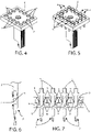
- the aforementioned boring machine according to the present invention also comprises a support 6 for housing the drill bit 3.
- This support 6 can be fixed, or anchored to the frame or to another fixed part of the boring machine, or mobile or mounted on a member or mobile device of the drilling machine itself.
- a plurality of through cavities 7 is formed in the support 6 to allow, each, the housing of a drill bit 3.
- each through cavity 7 there is provided a flared abutment portion 8 with a circular development, configured to realize precisely, an abutment with the threaded connection portion 5 of a drill bit 3.
- each flared portion 8 is covered with a layer of friction material 9, whose function will be better detailed later in this description.
- the aforementioned machine tool also comprises a control unit (not shown) for controlling the displacements of the operative head 1 and/or of the support 6.
- a drill bit 3 On a spindle 2 of the operative head 1, it is positioned above the support 6 carrying at least one drill bit 3 arranged in a respective through cavity 7, so that said spindle 2 is vertically aligned with the drill bit 3 (see fig. 8 ).
- the screwing of the threaded connection portion 5 of the drill bit 3 into the threaded seat 4 of the spindle 2 is made possible by the layer of friction material 9 provided in the contact area between the drill bit 3 and the support 6.
- the friction produced by the layer of friction material 9 generates, in fact, a resistance to the rotation, such as to keep the aforesaid drill bit 3 stationary until the screwing of the relative threaded connection portion 5 into the threaded seat 4 of the spindle 2 is completed; then allowing, once said screwing has been completed, the boring tip 3 itself to rotate together with the spindle 2.
- the operative head 1 is raised along the aforementioned vertical Z-axis to extract the same drill bit 3 from the respective through cavity 7 of the support 6 (see figure 13 ).
- this drill bit 3 from the relative spindle 2 is then necessary, in order to replace it or to interrupt the operating activity of the drilling machine, it is proceed by positioning the operative head 1 above the support 6 to obtain the vertical alignment between the spindle 2 having the drill tip 3, and a through cavity 7 of the support 6, and then controlling the lowering of the operative head 1 and/or of the spindle 1 along the vertical Z-axis up to arrange the drill tip 3 in this through cavity 7.
- the unscrewing of the threaded connection portion 5 of the boring tip 3 from the threaded seat 4 of the spindle 2 is made possible due to the resistance to the rotation determined by the layer of friction material 9, which allows keeping the drill bit 3, while the rotation of the spindle 2 is arranged to achieve the aforementioned unscrewing.
- Both the screwing and unscrewing operations described above could be performed simultaneously on two or more drill bits 3, as well as on a single drill bit 3 as indicated above; this allows increasing the advantages produced by the drilling machine according to the present invention, in terms of machine downtime reduction for the replacement of tools in the operative head.
- the aforesaid machine tool can also comprise two or more supports 6, positioned for example in a dedicated area of this machine (for example a magazine equipped with housings for such supports 6) or adjacent to it; in this case, the method according to the present invention can provide a first step, in which the operative head 1 drops off, according to the methods described above, the drill bits 3 mounted on the relative spindles 2 in an empty support 6 (i.e., with the relative through cavities 7 free), and a subsequent second step, in which the same operative head 1 moves towards a further support 6 carrying a plurality of drill bits 3 in the respective through cavities 7, to simultaneously pick-up said drill bits 3 through a single pick up operation.
- a first step in which the operative head 1 drops off, according to the methods described above, the drill bits 3 mounted on the relative spindles 2 in an empty support 6 (i.e., with the relative through cavities 7 free)
- a subsequent second step in which the same operative head 1 moves towards a further support 6 carrying a plurality of drill bits 3
- the machine tool according to this last constructive configuration has a particular flexibility of use and allows carrying out its tooling in a very short time.
- 6' indicates a second support for housing the drill bits 3.
- Said second support 6' comprises a plurality of rotatable driven gears 7', each around its own vertical rotation axis, in each of which a respective through cavity 8' is formed.
- the aforesaid driven gears 7' are meshed in series with each other and arranged in such a way as to form a closed path.
- the machine tool proposed here also comprises actuation means capable of placing said driving toothed wheel 9 'in rotation around the relative axis of vertical rotation, thus allowing the transmission of the rotary motion from the driving toothed wheel 9' to the driven gears 7'.
- This particular technical expedient allows achieving the screwing of the threaded connection portion 5 of the boring tip 3 into the threaded seat 4 of the spindle 2 by rotating the boring tip 3, instead of the spindle 2, by means of the aforementioned driven gears 7'.
- the aforesaid actuation means could be internal or external to said second support 6' and could comprise, for example, an electric motor or a compressed air system.
- the through cavities 7 are formed in respective support elements, which are also part of the support 6, rotatable around a respective vertical rotation axis and connected to an automatic friction device, configured in such a way as to keep these support elements stationary during the screwing and unscrewing operations of the drilling bits 3 and to allow the rotation of the same support elements once these operations have been completed, or as soon as the spindle detects a certain resistance to the rotation by the supporting elements.
- the aforementioned automatic friction device can be provided in the support 6, or in the operative head 1, or in another part of the machine tool.
- connection means can be provided to achieve a reciprocal connection between the spindles 2 and the drill bits 3 by means of a movement other than a rotation, such as for example a translational movement; in the latter case, snap connection means could be used, for example.
- the present invention is not intended to be limited to the use of drill bits 3, other types of tools may also be provided.
- the machine according to the present invention allows providing for the replacement of tools in the operative head in an automatic, fast, and safe way, with the direct consequence of reducing machine downtime to a minimum for changing the tools.
Landscapes
- Engineering & Computer Science (AREA)
- Mechanical Engineering (AREA)
- Automatic Tool Replacement In Machine Tools (AREA)
- Multi-Process Working Machines And Systems (AREA)
Abstract
Description
- The present invention relates to a machine tool with an automatic system for replacing tools.
- More specifically, the invention relates to a machine tool for machining workpieces comprising at least one operative head, equipped with at least one rotating spindle, and a system for allowing the automatic execution of the assembly and disassembly operations of the tools in said spindle.
- The invention proposed here also relates to a method for the automatic execution of tool changes.
- In the following, the description will be addressed to a drilling machine, but it is clear that it should not be considered limited to this specific use, as it can also be extended to machine tools of different types, that is, suitable for carrying out operations other than boring.
- To date, when the need arises to replace a tool mounted on the spindle of a machine tool with another tool due to operational needs, the operations for disassembling the tool in use and subsequent assembly of the new tool are normally carried out by an operator assigned to this task.
- This unavoidably involves rather a long downtime to allow the manual replacement of tools in the spindles, as well as the use of a human resource for this specific purpose.
- In addition to this, it must also be considered that the tool assembly operations may not be performed perfectly, just because they are carried out manually and not through an automatic system.
- In light of the above, it is therefore an object of the present invention to provide a machine tool that allows the replacement of tools in the relative spindles in an automatic way.
- Another object of the invention is to provide a machine tool that is such as to allow the replacement of the tools in the respective spindles in a quick and safe way, thus obtaining a significant reduction in the downtime normally required to allow the manual replacement of tools.
- A further object of the present invention is to provide a machine tool equipped with an automatic tool replacement system that is simple and effective.
- It is, therefore, specific object of the present invention a machine tool for machining workpieces, comprising: at least one operative head comprising a plurality of spindles rotatable about respective rotation axes which are parallel to one another and each provided with respective first coupling means being configured to provide, in use, a removable coupling with a respective tool for performing at least one machining operation on a workpiece; a supporting device where a plurality of seats is formed to removably house, in use, a plurality of tools; and a control unit for controlling the movement of said at least one operative head and/or said supporting device in such a way that when a spindle of said plurality of spindles is in contact with a tool of said plurality of tools which is placed in a seat of said supporting device, a removable mutual coupling between said spindle and said tool is achieved by said respective first coupling means.
- Preferably according to the invention, said respective first coupling means are configured to provide, in use, a removable coupling with a respective tool by a mutual rotation of said spindle and said tool.
- Preferably according to the invention, said control unit is able to command the movement of said at least one operative head and/or said supporting device in such a way as to simultaneously put a plurality of spindles into mutual contact with a plurality of tools.
- Advantageously according to the invention, said respective first coupling means may comprise a respective first thread.
- Further according to the invention, said respective first coupling means may comprise a respective seat, where said respective first thread is formed.
- Conveniently according to the invention, said machine may comprise at least one tool which is provided with second coupling means being configured to be removably coupled with said first coupling means of said at least one spindle.
- Still according to the invention, said second coupling means may comprise a second thread.
- Preferably according to the invention, the seats of said plurality of seats comprise holding means to prevent at least one tool placed in a seat from rotating relative to said seat when mutually coupling said first coupling means of a spindle and said at least one tool by a mutual rotation between said spindle and said at least one tool.
- Further according to the invention, said holding means may comprise friction means for providing, in use, a determined level of friction with said at least one tool.
- Still according to the invention, said holding means may comprise form-coupling means for providing, in use, a form coupling with at least one part of said at least one tool.
- Conveniently according to the invention, at least one seat of said supporting device may be rotatable about a respective rotation axis, and in that said machine tool comprises at least one clutch device, which is automatic, connected with said at least one seat being rotatable, and configured such that said at least one seat keeps stationary during the mutual coupling between a spindle and a tool placed in said at least one seat by rotating said spindle, and rotates about the respective rotation axis after the conclusion of mutual coupling between said spindle and said tool.
- Further according to the invention, said at least one clutch device may be comprised in said supporting device.
- Advantageously according to the invention, at least one seat of said supporting device may be rotatable about a respective rotation axis, and in that said machine tool comprises actuating means for rotating said at least one seat about said rotation axis.
- Still according to the invention, said machine may comprise a further supporting device where a plurality of seats is formed to removably house, in use, a plurality of tools.
- It is, also, object of the present invention a method for coupling a tool to a spindle of an operative head of a machine tool according to any one of preceding claims, wherein a plurality of tools is placed in a plurality of seats of said supporting device, said method comprising the steps of: moving said operative head and/or said supporting device in such a way as to put in mutual contact said plurality of spindles and said plurality of tools placed in said plurality of seats; and providing, by said first coupling means, a mutual removable coupling between said plurality of spindles and said plurality of tools.
- Preferably according to the invention, said mutual removable coupling between said plurality of spindles and said plurality of tools is executed simultaneously.
- Advantageously according to the invention, said mutual removable coupling between said plurality of spindles and said plurality of tools may be executed by a mutual rotation, according to a first rotation way, between each spindle and each tool placed in a seat.
- Further according to the invention, said method comprises the steps of: moving said operative head and/or said supporting device in such a way that a tool being mounted to a spindle is placed in a predetermined seat of said supporting device; and executing a mutual rotation, according to a second rotation way opposite with respect to said first rotation way, between said spindle and said predetermined seat such that said tool is decoupled from said spindle.
- Still according to the invention, said method may comprise the steps of: placing a plurality of tools mounted to a plurality of spindles in a plurality of seats of said supporting device; and coupling, to said plurality of spindles, a plurality of tools placed in a plurality of seats of said further supporting device.
- The present invention will be now described, for illustrative but not limitative purposes, according to its preferred embodiments, with particular reference to the figures of the enclosed drawings, wherein:
-
figure 1 is an axonometric view of an operative head of a machine tool according to the present invention; -
figure 2 is a side view of the operative head shown infigure 1 ; -
figure 3 is a bottom plan view of the operative head offigures 1 and 2 ; -
figure 4 is an axonometric view of a further component of a machine tool according to the present invention, in a first operating step of such machine tool; -
figure 5 is an axonometric view of the component shown infigure 4 associated with a plurality of tools for drilling, in a second operating step of the machine tool; -
figure 6 is a partial sectional view of a spindle of the operative head illustrated infigures 1-3 , associated with a drilling tool; -
figure 7 is a sectional view taken fromfigure 5 ; -
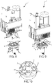
figure 8 shows the operative head offigures 1-3 and the component illustrated infigures 4-5 , in a first operating step; -
figure 9 shows the operative head offigures 1-3 and the component illustrated infigures 4-5 , in a second operating step; -
figure 10 is a detail view of the detail A indicated infigure 9 ; -
figure 11 shows the operative head offigures 1-3 and the component illustrated infigures 4-5 , in a third operating step; -
figure 12 is a detail view of detail B indicated infigure 11 ; -
figure 13 shows the operative head offigures 1-3 and the component illustrated infigures 4-5 , in a fourth operating step; -
figure 14 is an isometric view of a variant of the component shown infigure 4 ; -
figure 15 is a top view of what is shown infigure 14 ; -
figure 16 is an axonometric view of the component illustrated infigures 14 and 15 associated with a plurality of tools for drilling; -
figure 17 is a top view of what is shown infigure 16 ; and -
figure 18 is a sectional view taken fromfigure 17 . - In the various figures, similar parts will be indicated by the same reference numbers.
- With reference to the attached
figures, 1 indicates a mobile operative head of a drilling machine (not shown) according to the present invention. - Said
operative head 1 has, at the bottom, a plurality ofspindles 2 rotatable about respective rotation axes, parallel to each other. - In the
operative head 1 there is also a vertical movement system to move, independently, eachspindle 2 along the respective rotation axis, namely along a vertical Z-axis. - On the
spindles 2 are mounted, in a removable way, the tools necessary for the execution of the planned machining. - In the present case, illustrated in the figures attached hereto, these tools are
drill bits 3. - At the free end of each
spindle 2 there is a respective threadedseat 4 directed axially to thespindle 2 itself and configured to receive, in use, a corresponding threadedconnection portion 5 of adrill bit 3. - Each
drill bit 3 can therefore be disassembled from thecorresponding spindle 2 by unscrewing the relative threadedconnection portion 5 from the threadedseat 4 of thespindle 2 itself. - The aforementioned boring machine according to the present invention also comprises a
support 6 for housing thedrill bit 3. - This
support 6 can be fixed, or anchored to the frame or to another fixed part of the boring machine, or mobile or mounted on a member or mobile device of the drilling machine itself. - A plurality of through
cavities 7 is formed in thesupport 6 to allow, each, the housing of adrill bit 3. - In particular, in each through
cavity 7 there is provided a flaredabutment portion 8 with a circular development, configured to realize precisely, an abutment with the threadedconnection portion 5 of adrill bit 3. - Therefore, when a
drill bit 3 is housed in a throughcavity 7 of thesupport 6, saiddrill bit 3 completely passes through the throughcavity 7 remaining hanging on thesupport 6, or supported by this, due to the abutment made by the threadedconnection portion 5 of thedrill bit 3 on the flaredportion 8. - Furthermore, each flared
portion 8 is covered with a layer offriction material 9, whose function will be better detailed later in this description. - The aforementioned machine tool also comprises a control unit (not shown) for controlling the displacements of the
operative head 1 and/or of thesupport 6. - In case of, for operational requirements, it is necessary to mount a
drill bit 3 on aspindle 2 of theoperative head 1, it is positioned above thesupport 6 carrying at least onedrill bit 3 arranged in a respective throughcavity 7, so that saidspindle 2 is vertically aligned with the drill bit 3 (seefig. 8 ). - Subsequently, the lowering of the
spindle 2, and possibly also that of the entireoperative head 1, is arranged towards the underlying drill bit 3 (seefigures 9 and 10 ). - During this lowering step, when the
spindle 2, rotating around its own rotation axis, comes into contact with the threadedconnection portion 5 of thedrill bit 3, the progressive screwing of the same threadedconnection portion 5 into the threadedseat 4 occurs of thespindle 2, thus obtaining the coupling of thedrill bit 3 to the spindle 2 (seefigures 11 and 12 ). - The screwing of the threaded
connection portion 5 of thedrill bit 3 into the threadedseat 4 of thespindle 2 is made possible by the layer offriction material 9 provided in the contact area between thedrill bit 3 and thesupport 6. - The friction produced by the layer of
friction material 9 generates, in fact, a resistance to the rotation, such as to keep theaforesaid drill bit 3 stationary until the screwing of the relative threadedconnection portion 5 into the threadedseat 4 of thespindle 2 is completed; then allowing, once said screwing has been completed, theboring tip 3 itself to rotate together with thespindle 2. - This, therefore, avoids the need to keep under control the screwing step of the threaded
connection portion 5 of theboring tip 3 into the threadedseat 4 of thespindle 2, since the immediate interruption of the rotation of thespindle 2 is not required at the moment of the conclusion of this tightening step. - Once the threaded
connection portion 5 of theboring tip 3 has been screwed into the threadedseat 4 of thespindle 2, theoperative head 1 is raised along the aforementioned vertical Z-axis to extract thesame drill bit 3 from the respective throughcavity 7 of the support 6 (seefigure 13 ). - If disassembling this
drill bit 3 from therelative spindle 2 is then necessary, in order to replace it or to interrupt the operating activity of the drilling machine, it is proceed by positioning theoperative head 1 above thesupport 6 to obtain the vertical alignment between thespindle 2 having thedrill tip 3, and a throughcavity 7 of thesupport 6, and then controlling the lowering of theoperative head 1 and/or of thespindle 1 along the vertical Z-axis up to arrange thedrill tip 3 in this throughcavity 7. - At this point, to obtain the decoupling of the
drill tip 3 from thespindle 2, the rotation of the latter is arranged in the opposite direction to that necessary to achieve screwing. - Similarly to what has been indicated above, the unscrewing of the threaded
connection portion 5 of theboring tip 3 from the threadedseat 4 of thespindle 2 is made possible due to the resistance to the rotation determined by the layer offriction material 9, which allows keeping thedrill bit 3, while the rotation of thespindle 2 is arranged to achieve the aforementioned unscrewing. - Finally, once the threaded
connection portion 5 of thedrill bit 3 has been unscrewed from the threadedseat 4 of thespindle 2, theoperative head 1 is raised along the vertical Z-axis, leaving thedrill bit 3 in the throughcavity 7 of thesupport 6. - Both the screwing and unscrewing operations described above could be performed simultaneously on two or
more drill bits 3, as well as on asingle drill bit 3 as indicated above; this allows increasing the advantages produced by the drilling machine according to the present invention, in terms of machine downtime reduction for the replacement of tools in the operative head. - The aforesaid machine tool can also comprise two or
more supports 6, positioned for example in a dedicated area of this machine (for example a magazine equipped with housings for such supports 6) or adjacent to it; in this case, the method according to the present invention can provide a first step, in which theoperative head 1 drops off, according to the methods described above, thedrill bits 3 mounted on therelative spindles 2 in an empty support 6 (i.e., with the relative throughcavities 7 free), and a subsequent second step, in which the sameoperative head 1 moves towards afurther support 6 carrying a plurality ofdrill bits 3 in the respective throughcavities 7, to simultaneously pick-up saiddrill bits 3 through a single pick up operation. - The machine tool according to this last constructive configuration has a particular flexibility of use and allows carrying out its tooling in a very short time.
- With reference to a variant of the present invention, shown in
figures 14-18 , 6' indicates a second support for housing thedrill bits 3. - Said second support 6' comprises a plurality of rotatable driven gears 7', each around its own vertical rotation axis, in each of which a respective through cavity 8' is formed.
- The aforesaid driven gears 7' are meshed in series with each other and arranged in such a way as to form a closed path.
- In addition, in the second support 6 'there is a driving toothed wheel 9' meshed with a gear 7 'of the aforementioned plurality of driven gears 7'.
- The machine tool proposed here also comprises actuation means capable of placing said driving toothed wheel 9 'in rotation around the relative axis of vertical rotation, thus allowing the transmission of the rotary motion from the driving toothed wheel 9' to the driven gears 7'.
- This particular technical expedient allows achieving the screwing of the threaded
connection portion 5 of theboring tip 3 into the threadedseat 4 of thespindle 2 by rotating theboring tip 3, instead of thespindle 2, by means of the aforementioned driven gears 7'. - The aforesaid actuation means could be internal or external to said second support 6' and could comprise, for example, an electric motor or a compressed air system.
- In accordance with a further embodiment of the present invention, not illustrated in the attached figures, in place of the aforementioned layer of
friction material 9, it is possible to provide the throughcavities 7 of such a shape as to achieve a shape coupling with thedrill bits 3, in such a way that the latter remain stationary during the screwing and unscrewing operations performed by the rotation of thespindles 2. In this case, it is desirable that the throughcavities 7 are formed in respective support elements, which are also part of thesupport 6, rotatable around a respective vertical rotation axis and connected to an automatic friction device, configured in such a way as to keep these support elements stationary during the screwing and unscrewing operations of thedrilling bits 3 and to allow the rotation of the same support elements once these operations have been completed, or as soon as the spindle detects a certain resistance to the rotation by the supporting elements. - The aforementioned automatic friction device can be provided in the
support 6, or in theoperative head 1, or in another part of the machine tool. - According to further embodiments not shown in the figures, in the
spindles 2 of theoperative head 1, and also in the threadedconnection portion 5 of thedrill bits 3, connection means can be provided to achieve a reciprocal connection between thespindles 2 and thedrill bits 3 by means of a movement other than a rotation, such as for example a translational movement; in the latter case, snap connection means could be used, for example. - As highlighted above, the present invention is not intended to be limited to the use of
drill bits 3, other types of tools may also be provided. - It follows that the proposed invention relates, in a broad sense, to machine tools, and therefore not only to drilling machines.
- As can be seen from the above description, the machine according to the present invention allows providing for the replacement of tools in the operative head in an automatic, fast, and safe way, with the direct consequence of reducing machine downtime to a minimum for changing the tools.
- The present invention has been described for illustrative but not limitative purposes, according to its preferred embodiments, but it is to be understood that modifications and/or changes can be introduced by those skilled in the art without departing from the relevant scope as defined in the enclosed claims.
Claims (19)
- Machine tool for machining workpieces, comprising:- at least one operative head (1) comprising a plurality of spindles (2) rotatable about respective rotation axes which are parallel to one another and each provided with respective first coupling means (4) being configured to provide, in use, a removable coupling with a respective tool (3) for performing at least one machining operation on a workpiece;- a supporting device (6, 6') where a plurality of seats (7, 8') is formed to removably house, in use, a plurality of tools (3); and- a control unit for controlling the movement of said at least one operative head (1) and/or said supporting device (6, 6') in such a way that when a spindle (2) of said plurality of spindles (2) is in contact with a tool (3) of said plurality of tools (3) which is placed in a seat (7, 8') of said supporting device (6, 6'), a removable mutual coupling between said spindle (2) and said tool (3) is achieved by said respective first coupling means (4).
- Machine tool according to claim 1, characterised in that said respective first coupling means (4) are configured to provide, in use, a removable coupling with a respective tool (3) by a mutual rotation of said spindle (2) and said tool (3).
- Machine tool according to claim 1 or 2, characterised in that said control unit is able to command the movement of said at least one operative head (1) and/or said supporting device (6, 6') in such a way as to simultaneously put a plurality of spindles (2) into mutual contact with a plurality of tools (3).
- Machine tool according to claim 2, characterized in that said respective first coupling means (4) comprise a respective first thread.
- Machine tool according to claim 4, characterized in that said respective first coupling means comprise a respective seat (4) where said respective first thread is formed.
- Machine tool according to any one of preceding claims, characterized in that it comprises at least one tool (3) which is provided with second coupling means (5) being configured to be removably coupled with said first coupling means (4) of said at least one spindle (2).
- Machine tool according to claim 6, characterized in that said second coupling means (5) comprises a second thread.
- Machine tool according to any one of preceding claims, characterized in that the seats (7, 8') of said plurality of seats (7, 8') comprise holding means (9) to prevent at least one tool (3) placed in a seat (7, 8') from rotating relative to said seat (7, 8') when mutually coupling said first coupling means (4) of a spindle (2) and said at least one tool (3) by a mutual rotation between said spindle (2) and said at least one tool (3).
- Machine tool according to claim 8, characterized in that said holding means comprise friction means (9) for providing, in use, a determined level of friction with said at least one tool (3).
- Machine tool according to claim 8 or 9, characterized in that said holding means comprise form-coupling means for providing, in use, a form coupling with at least one part of said at least one tool (3).
- Machine tool according to claim 10, characterized in that at least one seat (8') of said supporting device (6') is rotatable about a respective rotation axis, and in that said machine tool comprises at least one clutch device, which is automatic, connected with said at least one seat (8') being rotatable, and configured such that said at least one seat (8') keeps stationary during the mutual coupling between a spindle (2) and a tool (3) placed in said at least one seat (8') by rotating said spindle (2), and rotates about the respective rotation axis after the conclusion of mutual coupling between said spindle (2) and said tool (3).
- Machine tool according to claim 11, characterized in that said at least one clutch device is comprised in said supporting device (6').
- Machine tool according to any one of preceding claims, characterized in that at least one seat (8') of said supporting device (6') is rotatable about a respective rotation axis, and in that said machine tool comprises actuating means for rotating said at least one seat (8') about said rotation axis.
- Machine tool according to any one of preceding claims, characterized in that it comprises a further supporting device (6, 6') where a plurality of seats (7, 8') is formed to removably house, in use, a plurality of tools (3).
- Method for coupling a tool (3) to a spindle (2) of an operative head (1) of a machine tool according to any one of preceding claims, wherein a plurality of tools (3) is placed in a plurality of seats (7, 8') of said supporting device (6, 6'), said method comprising the steps of:- moving said operative head (1) and/or said supporting device (6, 6') in such a way as to put in mutual contact said plurality of spindles (2) and said plurality of tools (3) placed in said plurality of seats (7, 8'); and- providing, by said first coupling means (4), a mutual removable coupling between said plurality of spindles (2) and said plurality of tools (3).
- Method according to claim 15, characterized in that said mutual removable coupling between said plurality of spindles (2) and said plurality of tools (3) is executed simultaneously.
- Method according to claim 15 or 16, characterized in that said mutual removable coupling between said plurality of spindles (2) and said plurality of tools (3) is executed by a mutual rotation, according to a first rotation way, between each spindle (2) and each tool (3) placed in a seat (7, 8').
- Method according to claim 17, characterized in that it comprises the steps of:- moving said operative head (1) and/or said supporting device (6, 6') in such a way that a tool (3) being mounted to a spindle (2) is placed in a predetermined seat (7, 8') of said supporting device (6, 6'); and- executing a mutual rotation, according to a second rotation way opposite with respect to said first rotation way, between said spindle (2) and said predetermined seat (7, 8') such that said tool (3) is decoupled from said spindle (2).
- Method according to any one of claims 15 to 18, said method being performable to couple a tool (3) to a spindle (2) of an operative head (1) of a machine tool according to claim 14, characterized in that it comprises the steps of:- placing a plurality of tools (3) mounted to a plurality of spindles (2) in a plurality of seats (7, 8') of said supporting device (6, 6'); and- coupling, to said plurality of spindles (2), a plurality of tools (3) placed in a plurality of seats (7, 8') of said further supporting device (6, 6').
Applications Claiming Priority (1)
| Application Number | Priority Date | Filing Date | Title |
|---|---|---|---|
| IT102020000032081A IT202000032081A1 (en) | 2020-12-23 | 2020-12-23 | MACHINE TOOL WITH AUTOMATIC SYSTEM FOR REPLACING TOOLS AND RELATED METHOD. |
Publications (1)
| Publication Number | Publication Date |
|---|---|
| EP4019175A1 true EP4019175A1 (en) | 2022-06-29 |
Family
ID=74875129
Family Applications (1)
| Application Number | Title | Priority Date | Filing Date |
|---|---|---|---|
| EP21213607.1A Pending EP4019175A1 (en) | 2020-12-23 | 2021-12-10 | Machine tool with an automatic system for replacing tools and related method |
Country Status (2)
| Country | Link |
|---|---|
| EP (1) | EP4019175A1 (en) |
| IT (1) | IT202000032081A1 (en) |
Citations (5)
| Publication number | Priority date | Publication date | Assignee | Title |
|---|---|---|---|---|
| DE2811357A1 (en) * | 1978-03-16 | 1979-09-27 | Norbert Ing Grad Ewertowski | Tool changer for multispindle drilling machine - has rotating arm to transfer sets of drills in particular configuration from magazine |
| DE3341252A1 (en) * | 1983-11-15 | 1985-05-30 | Otto Bilz, Werkzeugfabrik, 7302 Ostfildern | Automatic tool changer |
| DE20302387U1 (en) * | 2002-02-15 | 2003-04-24 | Biesse S.P.A., Pesaro | Drilling unit for parts made of wood or the like and associated tool spindle |
| EP1878549A1 (en) * | 2006-07-12 | 2008-01-16 | Weeke Bohrsysteme GmbH | Spindle unit |
| US20160368108A1 (en) * | 2015-06-18 | 2016-12-22 | Jorge Uriarte | Apparatus and a system for automatic tool change by threading engagement for a cnc milling machine |
-
2020
- 2020-12-23 IT IT102020000032081A patent/IT202000032081A1/en unknown
-
2021
- 2021-12-10 EP EP21213607.1A patent/EP4019175A1/en active Pending
Patent Citations (5)
| Publication number | Priority date | Publication date | Assignee | Title |
|---|---|---|---|---|
| DE2811357A1 (en) * | 1978-03-16 | 1979-09-27 | Norbert Ing Grad Ewertowski | Tool changer for multispindle drilling machine - has rotating arm to transfer sets of drills in particular configuration from magazine |
| DE3341252A1 (en) * | 1983-11-15 | 1985-05-30 | Otto Bilz, Werkzeugfabrik, 7302 Ostfildern | Automatic tool changer |
| DE20302387U1 (en) * | 2002-02-15 | 2003-04-24 | Biesse S.P.A., Pesaro | Drilling unit for parts made of wood or the like and associated tool spindle |
| EP1878549A1 (en) * | 2006-07-12 | 2008-01-16 | Weeke Bohrsysteme GmbH | Spindle unit |
| US20160368108A1 (en) * | 2015-06-18 | 2016-12-22 | Jorge Uriarte | Apparatus and a system for automatic tool change by threading engagement for a cnc milling machine |
Also Published As
| Publication number | Publication date |
|---|---|
| IT202000032081A1 (en) | 2022-06-23 |
Similar Documents
| Publication | Publication Date | Title |
|---|---|---|
| JP5284114B2 (en) | Mechanical apparatus for assembling and / or removing a laser nozzle, and laser processing machine equipped with such a mechanical apparatus | |
| KR101543791B1 (en) | Methods and systems for in-situ machine maintenance | |
| JP6025832B2 (en) | Electric spindle with tool changeable device | |
| CN111655411B (en) | Turret head for a machine tool | |
| KR20120006622A (en) | Multi Tapping Machine | |
| CN110948232A (en) | Automatic drilling and tapping equipment | |
| JP5843452B2 (en) | Robot and workpiece machining system | |
| JP2020049549A (en) | Robot unit | |
| KR101520264B1 (en) | Jig for caliper housing | |
| KR101972459B1 (en) | Cnc automatic feeder with maximized efficiency | |
| KR20130070245A (en) | Tool cleaning apparatus for a automatic tool changer | |
| CN120244675A (en) | A vertical rotary tool magazine, processing equipment and tool changing method | |
| CN117083141A (en) | Machine tool | |
| JP6415952B2 (en) | Machine Tools | |
| CN109890560A (en) | Computer Numerical Control Machining Device | |
| JP2008531300A (en) | Transfer machine for drill or drill bit production | |
| CN116475848B (en) | Multi-working-procedure integrated machine tool | |
| CN105784411A (en) | Automatic drill bit replacing device for indoor rock core drilling machine | |
| JPS6023936B2 (en) | Machine tools for flexible machining systems | |
| JP4805025B2 (en) | Rotary processing machine | |
| CN110625152B (en) | Precision machine tool flexible to operate | |
| KR102461865B1 (en) | Turret tool device of machine tool | |
| CN110449621B (en) | Safe type numerical control system of processing precision height | |
| EP0652074A1 (en) | Machining head for mechanically machining boards, in particular printed circuit boards | |
| CN116237794B (en) | Automatic tool changer |
Legal Events
| Date | Code | Title | Description |
|---|---|---|---|
| PUAI | Public reference made under article 153(3) epc to a published international application that has entered the european phase |
Free format text: ORIGINAL CODE: 0009012 |
|
| STAA | Information on the status of an ep patent application or granted ep patent |
Free format text: STATUS: THE APPLICATION HAS BEEN PUBLISHED |
|
| AK | Designated contracting states |
Kind code of ref document: A1 Designated state(s): AL AT BE BG CH CY CZ DE DK EE ES FI FR GB GR HR HU IE IS IT LI LT LU LV MC MK MT NL NO PL PT RO RS SE SI SK SM TR |
|
| STAA | Information on the status of an ep patent application or granted ep patent |
Free format text: STATUS: REQUEST FOR EXAMINATION WAS MADE |
|
| 17P | Request for examination filed |
Effective date: 20221223 |
|
| RBV | Designated contracting states (corrected) |
Designated state(s): AL AT BE BG CH CY CZ DE DK EE ES FI FR GB GR HR HU IE IS IT LI LT LU LV MC MK MT NL NO PL PT RO RS SE SI SK SM TR |
|
| P01 | Opt-out of the competence of the unified patent court (upc) registered |
Effective date: 20230518 |
|
| STAA | Information on the status of an ep patent application or granted ep patent |
Free format text: STATUS: EXAMINATION IS IN PROGRESS |
|
| 17Q | First examination report despatched |
Effective date: 20251015 |