EP4018167B1 - Messrohr eines coriolis-messaufnehmers, coriolis-messaufnehmer und coriolis-messgerät - Google Patents
Messrohr eines coriolis-messaufnehmers, coriolis-messaufnehmer und coriolis-messgerät Download PDFInfo
- Publication number
- EP4018167B1 EP4018167B1 EP20754186.3A EP20754186A EP4018167B1 EP 4018167 B1 EP4018167 B1 EP 4018167B1 EP 20754186 A EP20754186 A EP 20754186A EP 4018167 B1 EP4018167 B1 EP 4018167B1
- Authority
- EP
- European Patent Office
- Prior art keywords
- measuring tube
- measuring
- coriolis
- component
- tube wall
- Prior art date
- Legal status (The legal status is an assumption and is not a legal conclusion. Google has not performed a legal analysis and makes no representation as to the accuracy of the status listed.)
- Active
Links
Images
Classifications
-
- G—PHYSICS
- G01—MEASURING; TESTING
- G01F—MEASURING VOLUME, VOLUME FLOW, MASS FLOW OR LIQUID LEVEL; METERING BY VOLUME
- G01F1/00—Measuring the volume flow or mass flow of fluid or fluent solid material wherein the fluid passes through a meter in a continuous flow
- G01F1/76—Devices for measuring mass flow of a fluid or a fluent solid material
- G01F1/78—Direct mass flowmeters
- G01F1/80—Direct mass flowmeters operating by measuring pressure, force, momentum, or frequency of a fluid flow to which a rotational movement has been imparted
- G01F1/84—Coriolis or gyroscopic mass flowmeters
- G01F1/8409—Coriolis or gyroscopic mass flowmeters constructional details
- G01F1/8427—Coriolis or gyroscopic mass flowmeters constructional details detectors
-
- G—PHYSICS
- G01—MEASURING; TESTING
- G01F—MEASURING VOLUME, VOLUME FLOW, MASS FLOW OR LIQUID LEVEL; METERING BY VOLUME
- G01F1/00—Measuring the volume flow or mass flow of fluid or fluent solid material wherein the fluid passes through a meter in a continuous flow
- G01F1/76—Devices for measuring mass flow of a fluid or a fluent solid material
- G01F1/78—Direct mass flowmeters
- G01F1/80—Direct mass flowmeters operating by measuring pressure, force, momentum, or frequency of a fluid flow to which a rotational movement has been imparted
- G01F1/84—Coriolis or gyroscopic mass flowmeters
- G01F1/8409—Coriolis or gyroscopic mass flowmeters constructional details
- G01F1/8422—Coriolis or gyroscopic mass flowmeters constructional details exciters
-
- G—PHYSICS
- G01—MEASURING; TESTING
- G01F—MEASURING VOLUME, VOLUME FLOW, MASS FLOW OR LIQUID LEVEL; METERING BY VOLUME
- G01F1/00—Measuring the volume flow or mass flow of fluid or fluent solid material wherein the fluid passes through a meter in a continuous flow
- G01F1/76—Devices for measuring mass flow of a fluid or a fluent solid material
- G01F1/78—Direct mass flowmeters
- G01F1/80—Direct mass flowmeters operating by measuring pressure, force, momentum, or frequency of a fluid flow to which a rotational movement has been imparted
- G01F1/84—Coriolis or gyroscopic mass flowmeters
- G01F1/8409—Coriolis or gyroscopic mass flowmeters constructional details
- G01F1/844—Coriolis or gyroscopic mass flowmeters constructional details microfluidic or miniaturised flowmeters
-
- G—PHYSICS
- G01—MEASURING; TESTING
- G01F—MEASURING VOLUME, VOLUME FLOW, MASS FLOW OR LIQUID LEVEL; METERING BY VOLUME
- G01F15/00—Details of, or accessories for, apparatus of groups G01F1/00 - G01F13/00 insofar as such details or appliances are not adapted to particular types of such apparatus
- G01F15/006—Details of, or accessories for, apparatus of groups G01F1/00 - G01F13/00 insofar as such details or appliances are not adapted to particular types of such apparatus characterised by the use of a particular material, e.g. anti-corrosive material
-
- G—PHYSICS
- G01—MEASURING; TESTING
- G01N—INVESTIGATING OR ANALYSING MATERIALS BY DETERMINING THEIR CHEMICAL OR PHYSICAL PROPERTIES
- G01N9/00—Investigating density or specific gravity of materials; Analysing materials by determining density or specific gravity
- G01N9/002—Investigating density or specific gravity of materials; Analysing materials by determining density or specific gravity using variation of the resonant frequency of an element vibrating in contact with the material submitted to analysis
- G01N2009/006—Investigating density or specific gravity of materials; Analysing materials by determining density or specific gravity using variation of the resonant frequency of an element vibrating in contact with the material submitted to analysis vibrating tube, tuning fork
Definitions
- the invention relates to a measuring tube of a Coriolis sensor, such a Coriolis sensor and such a Coriolis measuring device.
- Coriolis measuring instruments such as those used in DE102015120087A1 shown, have measuring tubes through which a medium flows, the density or mass flow of which is to be measured.
- Such measuring devices have exciters for generating measuring tube vibrations and sensors for detecting measuring tube vibrations, whereby measured values for density and mass flow can be derived from vibration properties.
- These sensors and exciters comprise electrical/magnetic or electronic components, in many cases coils and magnets, which are attached to measuring tubes and are designed to vibrate against each other. For example, coils can be incorporated into LTCC ceramics. However, such components disturb the vibration behavior of measuring tubes, especially in the case of small measuring tubes.
- the object of the invention is therefore to propose a measuring tube as well as a Coriolis measuring sensor and a Coriolis measuring device in which the influence of sensor or excitation components on measuring tube vibrations is greatly reduced.
- the object is achieved by a measuring tube according to independent claim 1, by a Coriolis measuring sensor according to claim 7 and by a Coriolis measuring device according to claim 8.
- the measuring tube wall has a sintered ceramic or is made of a sintered ceramic.
- the ceramic is an LTCC ceramic and comprises at least one electrical or electronic component, wherein the component has a coil is.
- the coil can be part of an exciter or sensor, for example. If a coil is used as an exciter component, the coil is supplied with an electric current to form a magnetic field and can be caused to excite measuring tube vibrations using a further magnetic field. If a coil is used as a sensor component, the coil is moved relative to a magnetic field by measuring tube vibrations, thus inducing measurable electrical voltages that can be used to evaluate measuring tube vibrations.
- Temperature sensors for determining a media or measuring tube temperature can also be integrated into the measuring tube wall.
- electrical connections are provided for the electrical connection of the other components integrated into the measuring tube, which are arranged in an area with a low oscillation amplitude of the measuring tube oscillations.
- connections between electrical connections and electrical connections, for example connecting cables, are exposed to low mechanical stress.
- the components integrated into the measuring tube are electrically connected to conductor tracks integrated into the measuring tube.
- the component is applied to an outer surface of the measuring tube and/or integrated into the measuring tube wall and separated from the lumen by the measuring tube wall.
- the coil has a plurality of subsections and connecting pieces connecting adjacent subsections, wherein the subsections are arranged offset with respect to a coil axis and are separated from one another by LTCC ceramic, wherein subsections are formed as layers on or in the measuring tube wall.
- a cross-section of an outer surface of the measuring tube wall and/or a cross-section of an inner surface of the measuring tube wall delimiting the lumen follows one of the following geometric shapes: circle, ellipse, polygon with more than three corners, for example a rectangle or a square.
- the coil is made of a metal microparticle paste, wherein the metal is in particular silver and/or gold.
- the LTCC ceramic comprises, for example, at least one of the following materials: DuPont 948, DuPont 951, Ferro A6, Heraeus CT700, Heraeus CT800, Heraeus CT2000.
- a cross-sectional area of the lumen is less than 5 square millimeters, and in particular less than 3 square millimeters and preferably less than 2 square millimeters.
- the coil has two terminals for connecting electrical connecting lines.
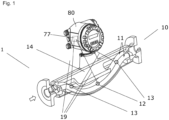
- Fig.1 outlines the structure of an exemplary schematic Coriolis measuring device 1 with an exemplary Coriolis measuring sensor 2 according to the invention, wherein the Coriolis measuring sensor has a vibration system with two measuring tubes 11, each with an inlet and an outlet, a carrier body 14 for carrying the measuring tubes, an exciter 12, and two sensors 13.
- the exciter is designed to excite the two measuring tubes to vibrate perpendicular to a measuring tube plane defined by the curved measuring tubes.
- the sensors are designed to detect the vibration imposed on the measuring tubes.
- the Coriolis sensor is connected to an electronic housing 80 of the Coriolis measuring device, which is designed to house an electronic measuring/operating circuit 77, which measuring/operating circuit is designed to operate the exciter and the sensors and to determine and provide flow measurement values and/or density measurement values based on vibration properties of the measuring tube measured by the sensors.
- the exciter and the sensors are connected to the electronic measuring/operating circuit by means of electrical connections 19.
- the electrical connections 19 can each be combined by cable guides.
- the Fig.1 The measuring tubes shown are exemplary and not according to the invention and serve purely to illustrate a Coriolis measuring device. Measuring tubes according to the invention are shown in Fig.2 It is no problem for the expert to Fig.1 shown measuring tubes with the in Fig. 2 to replace the measuring tubes shown and, if necessary, to adapt the carrier body and connections to a piping system.
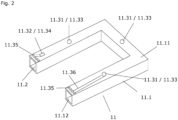
- Fig. 2 outlines an exemplary measuring tube 11 according to the invention, which has a measuring tube wall 11.1 and a measuring tube lumen 11.2, wherein the measuring tube wall has a sintered ceramic or is made of a sintered ceramic.
- Sintered measuring tubes have the advantage that a measuring tube geometry can be designed in a variety of ways.
- a cross-section of a measuring tube outer surface 11.11 of the measuring tube wall and a cross-section of a measuring tube inner surface 11.12 of the measuring tube wall delimiting the measuring tube lumen can be rectangular as shown here.
- the cross-sections can also each follow one of the following geometric shapes, for example: circle, ellipse, polygon with more than three corners such as a square.
- Green bodies i.e. sintered starting bodies
- Green bodies can be produced, for example, by means of 3D printing or by stacking and pressing several films of a starting material.
- Typical green bodies comprise at least one of the following materials: DuPont 948, DuPont 951, Ferro A6, Heraeus CT700, Heraeus CT800, Heraeus CT2000, whereby these materials contain, for example, Al 2 O 3 , CaAl 2 Si 2 O 8 or TiO 2 .
- Measuring tube production by sintering a ceramic is advantageous for measuring tubes in which the cross-sectional area of the measuring tube lumen is smaller than 5 square millimeters, and in particular smaller than 3 square millimeters and preferably smaller than 2 square millimeters.
- Such measuring tubes can only be manufactured using other methods in a more expensive and complicated way and allow less freedom in the choice of the geometric design of measuring tubes.
- the ceramic is designed as an LTCC ceramic and comprises the ceramic as in Fig.2 shown, at least one electrical or electronic component 11.3, wherein the component is a coil 11.31.
- the coil can be part of an exciter or sensor, for example. If a coil is used as an exciter component, the coil is supplied with an electric current to form a magnetic field and can be caused to excite measuring tube vibrations using a further magnetic field. If a coil is used as a sensor component, the coil is moved relative to a magnetic field by measuring tube vibrations, thus inducing measurable electrical voltages that can be used to evaluate measuring tube vibrations.
- Temperature sensors for determining a media or measuring tube temperature can also be integrated into the measuring tube wall.
- electrical connections are provided for the electrical connection of the other components integrated into the measuring tube, which are arranged, for example, in an area of low vibration amplitude of the measuring tube vibrations.
- connections between electrical connections and electrical connections for example connecting cables, are subjected to low mechanical loads.
- the components integrated into the measuring tube are electrically connected to conductor tracks 11.16 integrated into the measuring tube, whereby the conductor tracks can run on the measuring tube outer surface 11.11 or in the measuring tube wall.
- the expert selects the number and arrangement of such electrical connections according to his ideas and is not limited to the Fig. 2 shown design with 2 x 4 electrical connections.
- the electronic components or the coils 11.31 are each manufactured using a metal microparticle paste, whereby the metal microparticle paste comprises in particular silver and/or gold.
- Au5062D, Au5063D and Ag 5081 or Ag5082 are commercially available.
- the microparticle paste is applied to an area of the green compact corresponding to the outer surface of the measuring tube or is integrated into an area of the green compact corresponding to the wall of the measuring tube during the manufacture of the green compact.
- the microparticle paste can be applied to films before pressing. Sintering takes place after the green compact has been completed.
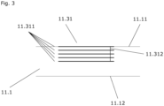
- a coil can be applied only to the outer surface of the measuring tube 11.11 or at least partially as in Fig.3 as sketched in the measuring tube wall 11.1.
- a Coriolis sensor or a Coriolis measuring device can have only one measuring tube according to the invention or several such measuring tubes. If there are several measuring tubes, two measuring tubes can be set up to oscillate against each other. In this case, electrical components of different measuring tubes of such a pair of measuring tubes can together form an exciter or a sensor, for example each comprising two capacitor plates or two coils. The electronic measuring/operating circuit is then set up to control the electronic components accordingly, or to read out and evaluate electrical currents and/or electrical voltages accordingly.
- Fig.3 outlines an arrangement of a coil 11.31, which is partially integrated into the measuring tube wall 11.1, whereby the coil has several sections 11.311 and connecting pieces 11.312 for the purpose of electrically connecting adjacent connecting pieces.
- the arrangement of the connecting pieces is purely schematic here; a specialist will set up connecting pieces and sections according to his ideas.
- a section can be applied to the measuring tube outer surface 11.11 as shown here. However, all sections can also be integrated into the measuring tube wall.
Landscapes
- Physics & Mathematics (AREA)
- General Physics & Mathematics (AREA)
- Fluid Mechanics (AREA)
- Chemical & Material Sciences (AREA)
- General Health & Medical Sciences (AREA)
- Biochemistry (AREA)
- Analytical Chemistry (AREA)
- Life Sciences & Earth Sciences (AREA)
- Immunology (AREA)
- Pathology (AREA)
- Health & Medical Sciences (AREA)
- Dispersion Chemistry (AREA)
- Measuring Volume Flow (AREA)
Description
- Die Erfindung betrifft ein Messrohr eines Coriolis-Messaufnehmers, einen solchen Coriolis-Messaufnehmer sowie ein solches Coriolis-Messgerät.
- Coriolis-Messgeräte wie beispielsweise in der
DE102015120087A1 gezeigt, weisen Messrohre auf, durch welche ein Medium strömt, dessen Dichte bzw. Massedurchfluss gemessen werden soll. Solche Messgeräte weisen Erreger zum Erzeugen von Messrohrschwingungen und Sensoren zum Erfassen von Messrohrschwingungen auf, wobei aus Schwingungseigenschaften Messwerte für Dichte und Massedurchfluss hergeleitet werden können. Diese Sensoren und Erreger umfassen elektrische/magnetische bzw. elektronische Bauteile, in vielen Fällen Spulen und Magnete, welche an Messrohren befestigt sind und dazu eingerichtet sind, gegeneinander zu schwingen. Beispielsweise können Spulen in LTCC-Keramiken eingearbeitet sein. Jedoch stören solche Bauteile das Schwingungsverhalten von Messrohren, insbesondere bei kleinen Messrohren. - Aufgabe der Erfindung ist es daher, ein Messrohr sowie ein Coriolis-Messaufnehmer sowie ein Coriolis-Messgerät vorzuschlagen, bei welchen der Einfluss von Sensor- bzw. Erregerbauteilen auf Messrohrschwingungen stark reduziert ist.
- Die Aufgabe wird gelöst durch ein Messrohr gemäß dem unabhängigen Anspruch 1, durch einen Coriolis-Messaufnehmer gemäß Anspruch 7 sowie durch ein Coriolis-Messgerät gemäß Anspruch 8.
- Bei einem erfindungsgemäßen Messrohr eines Coriolis-Messgeräts zum Messen einer Dichte bzw. eines Massedurchflusses eines durch das Messrohr strömenden Mediums mit einer Messrohrwandung und einem Messrohrlumen weist die Messrohrwandung eine gesinterte Keramik auf bzw. ist aus einer gesinterten Keramik gefertigt.
- Zudem ist die Keramik eine LTCC-Keramik und umfasst zumindest ein elektrisches oder elektronisches Bauteil, wobei das Bauteil eine
Spule ist. - Die Spule kann beispielsweise Bestandteil eines Erregers oder Sensors sein. Bei einer Spule als Erregerbestandteil wird die Spule mit einem elektrischen Strom zwecks Bildung eines Magnetfelds beaufschlagt und kann mittels eines weiteren Magnetfelds zur Anregung von Messrohrschwingungen veranlasst werden. Bei einer Spule als Sensorbestandteil wird die Spule durch Messrohrschwingungen relativ zu einem Magnetfeld bewegt und somit messbare elektrische Spannungen induziert, welche für eine Auswertung von Messrohrschwingungen verwendet werden können.
- Auch Temperatursensoren zwecks Bestimmung einer Medien- oder Messrohrtemperatur können in die Messrohrwand intergiert sein.
- Vorteilhafterweise sind elektrische Anschlüsse zur elektrischen Verbindung der weiteren in das Messrohr integrierten Bauteile vorgesehen, welche in einem Bereich geringer Schwingungsamplitude der Messrohrschwingungen angeordnet sind. Auf diese Weise sind Verbindungen zwischen elektrischen Anschlüssen und elektrischen Verbindungen, beispielsweise Verbindungskabeln geringen mechanischen Belastungen ausgesetzt. Die in das Messrohr integrierten Bauteile sind dabei mit in das Messrohr integrierten Leiterbahnen elektrisch verbunden.
- Das Bauteil ist auf eine Messrohraußenfläche aufgebracht und/oder in die Messrohrwandung integriert und vom Lumen durch die Messrohrwandung getrennt.
- Die Spule weist mehrere Teilabschnitte und benachbarte Teilabschnitte verbindende Verbindungsstücke auf, wobei die Teilabschnitte bzgl. einer Spulenachse versetzt angeordnet sind und durch LTCC-Keramik voneinander getrennt sind, wobei Teilabschnitte als Schichten auf oder in der Messrohrwandung ausgebildet sind.
- In einer Ausgestaltung folgt ein Querschnitt einer Außenfläche der Messrohrwandung und/oder ein Querschnitt einer das Lumen begrenzenden Innenfläche der Messrohrwandung einer der folgenden geometrischen Formen: Kreis, Ellipse, Vieleck mit mehr als drei Ecken beispielsweise ein Rechteck oder ein Quadrat.
- In einer Ausgestaltung ist die Spule aus einer Metall-Mikropartikelpaste gefertigt, wobei das Metall insbesondere Silber und/oder Gold ist.
- In einer Ausgestaltung weist die LTCC-Keramik beispielsweise zumindest eines der folgenden Materialien auf: DuPont 948, DuPont 951, Ferro A6, Heraeus CT700, Heraeus CT800, Heraeus CT2000.
- In einer Ausgestaltung ist eine Querschnittsfläche des Lumens kleiner als 5 Quadratmillimeter, und insbesondere kleiner als 3 Quadratmillimeter und bevorzugt kleiner als 2 Quadratmillimeter.
- In einer Ausgestaltung weist die Spule jeweils zwei Anschlüsse zum Anschließen von elektrischen Verbindungsleitungen auf.
- Ein erfindungsgemäßer Coriolis-Messaufnehmer eines Coriolis-Messgeräts zum Messen einer Dichte bzw. eines Massedurchflusses eines durch ein Messrohr strömenden Mediums umfasst:
- mindestens ein erfindungsgemäßes Messrohr,
- mindestens einen Erreger zum Erzeugen von Messrohrschwingungen,
- mindestens zwei Sensoren zum Erfassen von Messrohrschwingungen,
- einen Trägerkörper zum Tragen des Messrohrs,
- wobei ein Bauteil des Erregers und/oder jeweils mindestens ein Bauteil des Sensors Bestandteil des Messrohrs ist.
- Ein erfindungsgemäßes Coriolis-Messgerät zum Messen einer Dichte bzw. eines Massedurchflusses eines durch ein Messrohr strömenden Mediums umfasst:
- einen erfindungsgemäßen Coriolis-Messaufnehmer,
- eine elektronische Mess-/Betriebsschaltung eingerichtet zum Betreiben des Erregers sowie eingerichtet zum Bereitstellen von Messwerten der Dichte und/oder des Massedurchflusses auf Basis der durch die Sensoren erfassten
- Messrohrschwingungen,
- ein Elektronikgehäuse, in welchem die elektronische Mess-/Betriebsschaltung angeordnet ist.
- Im Folgenden wird die Erfindung anhand von Ausführungsbeispielen beschrieben.
-
Fig. 1 beschreibt einen Aufbau eines beispielhaften Coriolis-Messgeräts mit einem beispielhaften Coriolis-Messaufnehmer; -
Fig. 2 zeigt ein beispielhaftes erfindungsgemäßes Messrohr für ein Coriolis-Messgerät; -
Fig. 3 skizziert schematisch die Anordnung einer Spule in einer Messrohrwandung. -
Fig. 1 skizziert den Aufbau eines beispielhaften schematischen Coriolis-Messgeräts 1 mit einem beispielhaften erfindungsgemäßen Coriolis-Messaufnehmer 2, wobei der Coriolis-Messaufnehmer ein Schwingungssystem mit zwei Messrohren 11 mit jeweils einem Einlauf und einem Auslauf, einen Trägerkörper 14 zum Tragen der Messrohre, einen Erreger 12, und zwei Sensoren 13 aufweist. Der Erreger ist dazu eingerichtet, die beiden Messrohre senkrecht zu einer jeweils durch die bogenförmig ausgestalteten Messrohre definierten Messrohrebene zum Schwingen anzuregen. Die Sensoren sind dazu eingerichtet, die den Messrohren aufgeprägte Schwingung zu erfassen. Der Coriolis-Messaufnehmer ist mit einem Elektronikgehäuse 80 des Coriolis-Messgeräts verbunden, welches dazu eingerichtet ist, eine elektronische Mess-/Betriebsschaltung 77 zu behausen, welche Mess-/Betriebsschaltung dazu eingerichtet ist, den Erreger sowie die Sensoren zu betrieben und auf Basis von mittels der Sensoren gemessenen Schwingungseigenschaften des Messrohrs Durchflussmesswerte und/oder Dichtemesswerte zu ermitteln und bereitzustellen. Der Erreger sowie die Sensoren sind mittels elektrischer Verbindungen 19 mit der elektronischen Mess-/Betriebsschaltung verbunden. Die elektrischen Verbindungen 19 können jeweils durch Kabelführungen zusammengefasst sein. Die inFig. 1 gezeigten Messrohre sind beispielhaft und nicht erfindungsgemäß und dienen rein der Darstellung eines Coriolis-Messgeräts. Erfindungsgemäße Messrohre sind inFig. 2 gezeigt. Es stellt für den Fachmann kein Problem dar, die inFig. 1 gezeigten Messrohre mit den inFig. 2 gezeigten Messrohren auszutauschen und gegebenenfalls den Trägerkörper sowie Anbindungen an ein Rohrleitungssystem anzupassen. -
Fig. 2 skizziert ein beispielhaftes erfindungsgemäßes Messrohr 11, welches eine Messrohrwandung 11.1 und ein Messrohrlumen 11.2 aufweist, wobei die Messrohrwandung eine gesinterte Keramik aufweist bzw. aus einer gesinterten Keramik gefertigt ist. Gesinterte Messrohre weisen den Vorteil auf, dass eine Messrohrgeometrie vielfältig ausgestaltet werden kann. Ein Querschnitt einer Messrohraußenfläche 11.11 der Messrohrwandung und ein Querschnitt einer das Messrohrlumen begrenzenden Messrohrinnenfläche 11.12 der Messrohrwandung kann dabei wie hier gargestellt rechteckig sein. Die Querschnitte können jedoch auch jeweils beispielweise einer der folgenden geometrischen Formen folgen: Kreis, Ellipse, Vieleck mit mehr als drei Ecken wie beispielsweise ein Quadrat. Entlang einer Messrohrmittenlinie können solche Querschnitte auch variierend ausgestaltet sein, um beispielsweise eine Strömung des Mediums im Messrohr oder Schwingungseigenschaften des Messrohrs vorteilhaft auszugestalten. Grünkörper, also Sinterausgangskörper, können dabei beispielsweise mittels 3D-Druck oder durch Übereinanderstapeln und Verpressen mehrerer Folien eines Ausgangsmaterials hergestellt werden. Typische Grünkörper umfassen dabei zumindest eines der folgenden Materialien: DuPont 948, DuPont 951, Ferro A6, Heraeus CT700, Heraeus CT800, Heraeus CT2000, wobei diese Materialien beispielsweise Al2O3, CaAl2Si2O8 oder TiO2 aufweisen. - Vorteilhaft ist eine Messrohrherstellung mittels Sinterns einer Keramik bei Messrohren, bei welchen eine Querschnittsfläche des Messrohrlumens kleiner ist als 5 Quadratmillimeter, und insbesondere kleiner als 3 Quadratmillimeter und bevorzugt kleiner als 2 Quadratmillimeter. Solche Messrohre lassen sich mit anderen Verfahren nur auf eine teurere und kompliziertere Art und Weise fertigen und erlauben weniger Freiheit bei der Wahl der geometrischen Ausgestaltung von Messrohren.
- Erfindungsgemäß ist die Keramik als eine LTCC-Keramik ausgebildet und umfaßt die Keramik, wie in
Fig. 2 gezeigt, zumindest ein elektrisches oder elektronisches Bauteil 11.3 , wobei das Bauteil eine Spule 11.31 ist. - Die Spule kann beispielsweise Bestandteil eines Erregers oder Sensors sein. Bei einer Spule als Erregerbestandteil wird die Spule mit einem elektrischen Strom zwecks Bildung eines Magnetfelds beaufschlagt und kann mittels eines weiteren Magnetfelds zur Anregung von Messrohrschwingungen veranlasst werden. Bei einer Spule als Sensorbestandteil wird die Spule durch Messrohrschwingungen relativ zu einem Magnetfeld bewegt und somit messbare elektrische Spannungen induziert, welche für eine Auswertung von Messrohrschwingungen verwendet werden können.
- Auch Temperatursensoren zwecks Bestimmung einer Medien- oder Messrohrtemperatur können in die Messrohrwand intergiert sein.
- Vorteilhafterweise sind elektrische Anschlüsse zur elektrischen Verbindung der weiteren in das Messrohr integrierten Bauteile vorgesehen, welche beispielsweise in einem Bereich geringer Schwingungsamplitude der Messrohrschwingungen angeordnet sind. Auf diese Weise sind Verbindungen zwischen elektrischen Anschlüssen und elektrischen Verbindungen, beispielsweise Verbindungskabeln geringen mechanischen Belastungen ausgesetzt. Die in das Messrohr integrierten Bauteile sind dabei mit in das Messrohr integrierten Leiterbahnen 11.16 elektrisch verbunden, wobei die Leiterbahnen auf der Messrohraußenfläche 11.11 oder in der Messrohrwandung verlaufen können. Der Fachmann wählt Anzahl und Anordnung solcher elektrischen Anschlüsse gemäß seinen Vorstellungen und ist nicht auf die in
Fig. 2 gezeigte Ausgestaltung mit 2 mal 4 elektrischen Anschlüssen beschränkt. - Die elektronischen Bauteile bzw. die Spulen 11.31 sind jeweils mittels einer Metall-Mikropartikelpaste gefertigt, wobei die Metall-Mikropartikelpaste insbesondere Silber und/oder Gold umfasst. Handelsüblich sind dabei Au5062D, Au5063D sowie Ag 5081, oder Ag5082. Die Mikropartikelpaste ist dabei auf eine der Messrohraußenfläche entsprechenden Fläche des Grünlings aufgetragen oder während der Fertigung des Grünlings in einen der Messrohrwandung entsprechenden Bereich des Grünlings integriert. Beispielsweise kann die Mikropartikelpaste vor Verpressen auf Folien aufgebracht werden. Das Sintern findet nach Fertigstellung des Grünlings statt.
- Eine Spule können dabei nur auf der Messrohraußenfläche 11.11 aufgebracht oder auch zumindest teilweise wie in
Fig. 3 skizziert in die Messrohrwandung 11.1 integriert sein. - Ein Coriolis-Messaufnehmer bzw. ein Coriolis-Messgerät kann dabei nur ein erfindungsgemäßes Messrohr oder auch mehrere solcher Messrohre aufweisen. Bei Vorliegen mehrerer Messrohre können beispielsweise zwei Messrohre dazu eingerichtet sein, gegeneinander zu schwingen. In diesem Fall können elektrische Bauteile verschiedener Messrohre eines solchen Messrohrpaars gemeinsam einen Erreger oder einen Sensor, beispielsweise jeweils umfassend zwei Kondensatorplatten oder zwei Spulen, ausbilden. Die elektronische Mess-/Betriebsschaltung ist dann dazu eingerichtet, die elektronischen Bauteile entsprechend anzusteuern, bzw. elektrische Ströme und/oder elektrische Spannungen entsprechend auszulesen und auszuwerten.
-
Fig. 3 skizziert eine Anordnung einer Spule 11.31, welche teilweise in die Messrohrwandung 11.1 integriert ist, wobei die Spule mehrere Teilabschnitte 11.311 und Verbindungsstücke 11.312 zwecks elektrischer Verbindung von benachbarten Verbindungsstücken aufweist. Die Anordnung der Verbindungsstücke ist hierbei rein schematisch, ein Fachmann wird Verbindungsstücke und Teilabschnitte gemäß seinen Vorstellungen einrichten. Ein Teilabschnitt kann wie hier gezeigt auf der Messrohraußenfläche 11.11 aufgebracht sein. Es können aber auch sämtliche Teilabschnitte in die Messrohrwandung integriert sein. -
- 1
- Coriolis-Messgerät
- 10
- Coriolis-Messaufnehmer
- 11
- Messrohr
- 11.1
- Messrohrwandung
- 11.11
- Messrohraußenfläche
- 11.12
- Messrohrinnenfläche
- 11.2
- Messrohrlumen
- 11.3
- elektronisches Bauteil
- 11.31
- Spule
- 11.311
- Teilabschnitt
- 11.312
- Verbindungsstück
- 11.32
- Temperatursensor
- 11.33
- Kondensatorplatte
- 11.34
- Dehnungssensor
- 11.35
- elektrischer Anschluss
- 11.36
- elektrische Leiterbahn
- 12
- Erreger
- 13
- Sensor
- 14
- Trägerkörper
- 77
- elektronische Mess-/Betriebsschaltung
- 80
- Elektronikgehäuse
Claims (8)
- Messrohr (1) eines Coriolis-Messaufnehmers (10) zum Messen einer Dichte bzw. eines Massedurchflusses eines durch ein Messrohr strömenden Mediums,wobei das Messrohr (11) eine Messrohrwandung (11.1) und ein Messrohrlumen (11.2) aufweist,wobei die Messrohrwandung aus einer gesinterten Keramik gefertigt ist,wobei die Keramik eine LTCC-Keramik ist und zumindest ein elektrisches oder elektronisches Bauteil (11.3) umfasst, welches Bauteil auf eine Messrohraußenfläche (11.11) aufgebracht und/oder in die Messrohrwandung integriert ist und welches Bauteil vom Messrohrlumen durch die Messrohrwandung getrennt ist,wobei das Bauteil eine Spule (11.31) ist, die mehrere Teilabschnitte (11.311) und benachbarte Teilabschnitte verbindende Verbindungsstücke (11.312) aufweist,wobei die Teilabschnitte bzgl. einer Spulenachse versetzt angeordnet und durch LTCC-Keramik voneinander getrennt sind,und wobei Teilabschnitte als Schichten auf oder in der Messrohrwandung ausgebildet sind.
- Messrohr nach Anspruch 1, wobei ein Querschnitt einer Messrohraußenfläche (11.11) der Messrohrwandung und/oder ein Querschnitt einer das Messrohrlumen begrenzenden Messrohrinnenfläche (11.12) der Messrohrwandung einer der folgenden geometrischen Formen folgt: Kreis, Ellipse, Vieleck mit mehr als drei Ecken, insb. ein Rechteck oder ein Quadrat.
- Messrohr nach einem der vorigen Ansprüche, wobei das elektronische Bauteil aus einer Metall-Mikropartikelpaste gefertigt ist, wobei das Metall insbesondere Silber und/oder Gold ist.
- Messrohr nach einem der vorigen Ansprüche, wobei die LTCC-Keramik zumindest eines der folgenden Materialien aufweist: DuPont 948, DuPont 951, Ferro A6, Heraeus CT700, Heraeus CT800, Heraeus CT2000.
- Messrohr nach einem der vorigen Ansprüche, wobei eine Querschnittsfläche des Messrohrlumens (11.2) kleiner ist als 5 Quadratmillimeter, und insbesondere kleiner als 3 Quadratmillimeter und bevorzugt kleiner als 2 Quadratmillimeter.
- Messrohr nach einem der vorigen Ansprüche, wobei das Bauteil jeweils mit zwei elektrischen Anschlüssen (11.35) zum Anschließen von elektrischen Verbindungsleitungen verbunden ist.
- Coriolis-Messaufnehmer (10) eines Coriolis-Messgeräts (1) zum Messen einer Dichte bzw. eines Massedurchflusses eines durch ein Messrohr strömenden Mediums umfassend:mindestens ein Messrohr (11) nach einem der vorigen Ansprüche,mindestens einen Erreger (12) zum Erzeugen von Messrohrschwingungen,mindestens zwei Sensoren (13) zum Erfassen von Messrohrschwingungen,einen Trägerkörper (14) zum Tragen des Messrohrs,wobei mindestens ein Bauteil des Erregers und/oder jeweils mindestens ein Bauteil des Sensors Bestandteil des Messrohrs (11) ist.
- Coriolis-Messgerät (1) zum Messen einer Dichte bzw. eines Massedurchflusses eines durch ein Messrohr strömenden Mediums umfassend:einen Coriolis-Messaufnehmer (10) nach dem vorigen Anspruch,eine elektronische Mess-/Betriebsschaltung (77) eingerichtet zum Betreiben des Erregers sowie eingerichtet zum Bereitstellen von Messwerten der Dichte und/oder des Massedurchflusses auf Basis der durch die Sensoren erfassten Messrohrschwingungen,ein Elektronikgehäuse (80), in welchem die elektronische Mess-/Betriebsschaltung angeordnet ist.
Applications Claiming Priority (2)
| Application Number | Priority Date | Filing Date | Title |
|---|---|---|---|
| DE102019122210.9A DE102019122210B3 (de) | 2019-08-19 | 2019-08-19 | Messrohr eines Coriolis-Messaufnehmers mit einer LTCC-Keramik, Coriolis-Messaufnehmer mit einem solchen Messrohr und Coriolis-Messgerät mit einem solchen Coriolis-Messaufnehmer. |
| PCT/EP2020/071812 WO2021032454A1 (de) | 2019-08-19 | 2020-08-03 | Messrohr eines coriolis-messaufnehmers, coriolis-messaufnehmer und coriolis-messgerät |
Publications (2)
| Publication Number | Publication Date |
|---|---|
| EP4018167A1 EP4018167A1 (de) | 2022-06-29 |
| EP4018167B1 true EP4018167B1 (de) | 2024-07-31 |
Family
ID=72046852
Family Applications (1)
| Application Number | Title | Priority Date | Filing Date |
|---|---|---|---|
| EP20754186.3A Active EP4018167B1 (de) | 2019-08-19 | 2020-08-03 | Messrohr eines coriolis-messaufnehmers, coriolis-messaufnehmer und coriolis-messgerät |
Country Status (5)
| Country | Link |
|---|---|
| US (1) | US20220291031A1 (de) |
| EP (1) | EP4018167B1 (de) |
| CN (1) | CN114222900A (de) |
| DE (1) | DE102019122210B3 (de) |
| WO (1) | WO2021032454A1 (de) |
Family Cites Families (19)
| Publication number | Priority date | Publication date | Assignee | Title |
|---|---|---|---|---|
| US4803867A (en) * | 1987-04-28 | 1989-02-14 | Dahlin Erik B | Fluid measurement apparatus providing flow tube strain relief |
| US5373745A (en) * | 1991-02-05 | 1994-12-20 | Direct Measurement Corporation | Single path radial mode Coriolis mass flow rate meter |
| DE4445591C2 (de) * | 1994-10-07 | 1997-10-16 | Krohne Messtechnik Kg | Magnetisch-induktives Durchflußmeßgerät für strömende Medien |
| DE10003784B4 (de) * | 1999-12-27 | 2004-12-09 | Krohne Ag | Coriolis-Massendurchflußmeßgerät |
| AU2002330154A1 (en) * | 2001-09-28 | 2003-04-07 | Centre National De La Recherche Scientifique | Methods and compositions for treating hepatitis c virus using 4'-modified nucleosides |
| US7127952B2 (en) * | 2004-07-23 | 2006-10-31 | Endress + Hauser Flowtec Ag | Vibration-type measurement pickup for measuring media flowing in two medium-lines, and inline measuring device having such a pickup |
| US20090075129A1 (en) * | 2004-12-27 | 2009-03-19 | Integrated Sensing Systems, Inc. | Microfluidic device and method of use |
| US7228735B2 (en) * | 2005-02-03 | 2007-06-12 | Integrated Sensing Systems, Inc. | Fluid sensing device with integrated bypass and process therefor |
| US8447536B2 (en) * | 2007-06-30 | 2013-05-21 | Endress + Hauser Flowtec Ag | Medium density measuring system |
| DE102007062397A1 (de) * | 2007-12-20 | 2009-06-25 | Endress + Hauser Flowtec Ag | Meßwandler vom Vibrationstyp |
| DE102009012474A1 (de) * | 2009-03-12 | 2010-09-16 | Endress + Hauser Flowtec Ag | Meßsystem mit einem Messwandler vom Vibrationstyp |
| AU2009352333B2 (en) * | 2009-09-14 | 2013-06-13 | Micro Motion, Inc. | Corrosion-resistant coating for a vibratory flowmeter and method for forming the coating |
| DE102013021915A1 (de) * | 2013-12-27 | 2015-07-02 | Endress + Hauser Flowtec Ag | Meßaufnehmer vom Vibrationstyp |
| JP6395860B2 (ja) * | 2014-04-21 | 2018-09-26 | マイクロ モーション インコーポレイテッド | 位置割出し用のボスを備えた流量計のマニホールド |
| DE102014119073A1 (de) * | 2014-12-18 | 2016-06-23 | Endress+Hauser Flowtec Ag | Messaufnehmer vom Vibrationstyp |
| JP2018527578A (ja) * | 2015-09-15 | 2018-09-20 | マイクロ モーション インコーポレイテッド | 流量計用の衛生的なマニホールド |
| DE102015120087B4 (de) * | 2015-11-19 | 2025-12-24 | Endress + Hauser Flowtec Ag | Coriolis-Durchfluss- und/oder Coriolis-Dichtemessgerät mit einem Messaufnehmer vom Vibrationstyp und Verwendung des Coriolis-Durchfluss- und/oder Coriolis-Dichtemessgerätes |
| WO2019017891A1 (en) * | 2017-07-18 | 2019-01-24 | Micro Motion, Inc. | INTERCHANGEABLE FLOW METER FLOWMETER SENSOR AND CORRESPONDING METHOD |
| CN112088291A (zh) * | 2018-05-15 | 2020-12-15 | 高准公司 | 用于高温的线圈换能器 |
-
2019
- 2019-08-19 DE DE102019122210.9A patent/DE102019122210B3/de active Active
-
2020
- 2020-08-03 WO PCT/EP2020/071812 patent/WO2021032454A1/de not_active Ceased
- 2020-08-03 CN CN202080057372.1A patent/CN114222900A/zh active Pending
- 2020-08-03 US US17/636,126 patent/US20220291031A1/en not_active Abandoned
- 2020-08-03 EP EP20754186.3A patent/EP4018167B1/de active Active
Non-Patent Citations (1)
| Title |
|---|
| KEN A PETERSON ET AL: "SANDIA REPORT Macro-Meso-Microsystems Integration in LTCC: LDRD Report", 1 March 2007 (2007-03-01), pages 1 - 90, XP055360028, Retrieved from the Internet <URL:http://prod.sandia.gov/techlib/access-control.cgi/2007/071871.pdf> [retrieved on 20170329] * |
Also Published As
| Publication number | Publication date |
|---|---|
| EP4018167A1 (de) | 2022-06-29 |
| DE102019122210B3 (de) | 2021-01-28 |
| US20220291031A1 (en) | 2022-09-15 |
| CN114222900A (zh) | 2022-03-22 |
| WO2021032454A1 (de) | 2021-02-25 |
Similar Documents
| Publication | Publication Date | Title |
|---|---|---|
| EP3899444B1 (de) | Ultraschall-messgerät | |
| DE102015120087B4 (de) | Coriolis-Durchfluss- und/oder Coriolis-Dichtemessgerät mit einem Messaufnehmer vom Vibrationstyp und Verwendung des Coriolis-Durchfluss- und/oder Coriolis-Dichtemessgerätes | |
| DE4119903C5 (de) | Verfahren und Vorrichtung zur Messung dünner Schichten | |
| EP3999817B1 (de) | Coriolis-messaufnehmer und coriolis-messgerät mit coriolis-messaufnehmer | |
| EP3746750B1 (de) | Coriolis-messaufnehmer und coriolis-messgerät | |
| WO2015135739A1 (de) | Wandlervorrichtung sowie damit gebildetes messsystem | |
| EP3665445B1 (de) | Spule sowie messwandler mit einer solchen spule | |
| DE102010056279A1 (de) | Vortex-Durchflussmessgerät mit optimierter Temperaturerfassung | |
| EP3762689B1 (de) | Coriolismessgerät | |
| EP3837504B1 (de) | Messaufnehmer eines messgeräts und messgerät | |
| EP4018167B1 (de) | Messrohr eines coriolis-messaufnehmers, coriolis-messaufnehmer und coriolis-messgerät | |
| EP3833940B1 (de) | Messaufnehmer und messgerät | |
| EP4062129B1 (de) | Magnetisch-induktive durchflussmesssonde | |
| Krishnapriya et al. | Significance of non-spiral planar microcoils over spiral coils for biomedical applications: Design, simulation and comparison with spiral coil | |
| EP0737303B1 (de) | Magnetisch-induktives messgerät für strömende medien | |
| EP3833942B1 (de) | Spulenvorrichtung eines schwingungssensors oder schwingungserregers und messaufnehmer bzw. messgerät | |
| DE102005003398A1 (de) | Vorrichtung zur Bestimmung und/oder Überwachung des Volumen- und/oder Massendurchflusses | |
| DE102020211083A1 (de) | Sensorsystem und Verfahren zum Betrieb eines Sensorsystems | |
| DE4445591C2 (de) | Magnetisch-induktives Durchflußmeßgerät für strömende Medien | |
| WO2020120092A1 (de) | Coriolis-messaufnehmer eines coriolis-messgeräts und ein coriolis-messgerät | |
| DE102019122283A1 (de) | Messvorrichtung und Verfahren für ihre Herstellung | |
| DE102005040858B4 (de) | Vorrichtung zum Erfassen von elektromagnetischen Eigenschaften eines Prüfgegenstands | |
| WO2021052707A1 (de) | Coriolis-messaufnehmer und coriolis-messgerät | |
| DE102022133715A1 (de) | Modulares Coriolis-Durchflussmessgerät | |
| DE102019134600A1 (de) | Messaufnehmer und Coriolis-Messgerät |
Legal Events
| Date | Code | Title | Description |
|---|---|---|---|
| STAA | Information on the status of an ep patent application or granted ep patent |
Free format text: STATUS: UNKNOWN |
|
| STAA | Information on the status of an ep patent application or granted ep patent |
Free format text: STATUS: THE INTERNATIONAL PUBLICATION HAS BEEN MADE |
|
| PUAI | Public reference made under article 153(3) epc to a published international application that has entered the european phase |
Free format text: ORIGINAL CODE: 0009012 |
|
| STAA | Information on the status of an ep patent application or granted ep patent |
Free format text: STATUS: REQUEST FOR EXAMINATION WAS MADE |
|
| 17P | Request for examination filed |
Effective date: 20220127 |
|
| AK | Designated contracting states |
Kind code of ref document: A1 Designated state(s): AL AT BE BG CH CY CZ DE DK EE ES FI FR GB GR HR HU IE IS IT LI LT LU LV MC MK MT NL NO PL PT RO RS SE SI SK SM TR |
|
| DAV | Request for validation of the european patent (deleted) | ||
| DAX | Request for extension of the european patent (deleted) | ||
| STAA | Information on the status of an ep patent application or granted ep patent |
Free format text: STATUS: EXAMINATION IS IN PROGRESS |
|
| 17Q | First examination report despatched |
Effective date: 20231011 |
|
| GRAP | Despatch of communication of intention to grant a patent |
Free format text: ORIGINAL CODE: EPIDOSNIGR1 |
|
| STAA | Information on the status of an ep patent application or granted ep patent |
Free format text: STATUS: GRANT OF PATENT IS INTENDED |
|
| RIC1 | Information provided on ipc code assigned before grant |
Ipc: G01N 9/00 20060101ALI20240328BHEP Ipc: G01F 15/00 20060101ALI20240328BHEP Ipc: G01F 1/84 20060101AFI20240328BHEP |
|
| INTG | Intention to grant announced |
Effective date: 20240422 |
|
| GRAS | Grant fee paid |
Free format text: ORIGINAL CODE: EPIDOSNIGR3 |
|
| GRAA | (expected) grant |
Free format text: ORIGINAL CODE: 0009210 |
|
| STAA | Information on the status of an ep patent application or granted ep patent |
Free format text: STATUS: THE PATENT HAS BEEN GRANTED |
|
| AK | Designated contracting states |
Kind code of ref document: B1 Designated state(s): AL AT BE BG CH CY CZ DE DK EE ES FI FR GB GR HR HU IE IS IT LI LT LU LV MC MK MT NL NO PL PT RO RS SE SI SK SM TR |
|
| REG | Reference to a national code |
Ref country code: CH Ref legal event code: EP Ref country code: GB Ref legal event code: FG4D Free format text: NOT ENGLISH |
|
| REG | Reference to a national code |
Ref country code: DE Ref legal event code: R096 Ref document number: 502020008754 Country of ref document: DE |
|
| REG | Reference to a national code |
Ref country code: IE Ref legal event code: FG4D Free format text: LANGUAGE OF EP DOCUMENT: GERMAN |
|
| P01 | Opt-out of the competence of the unified patent court (upc) registered |
Free format text: CASE NUMBER: APP_48882/2024 Effective date: 20240827 |
|
| RAP4 | Party data changed (patent owner data changed or rights of a patent transferred) |
Owner name: ENDRESS+HAUSER FLOWTEC AG |
|
| PGFP | Annual fee paid to national office [announced via postgrant information from national office to epo] |
Ref country code: CH Payment date: 20240901 Year of fee payment: 5 |
|
| REG | Reference to a national code |
Ref country code: LT Ref legal event code: MG9D |
|
| REG | Reference to a national code |
Ref country code: NL Ref legal event code: MP Effective date: 20240731 |
|
| PG25 | Lapsed in a contracting state [announced via postgrant information from national office to epo] |
Ref country code: PT Free format text: LAPSE BECAUSE OF FAILURE TO SUBMIT A TRANSLATION OF THE DESCRIPTION OR TO PAY THE FEE WITHIN THE PRESCRIBED TIME-LIMIT Effective date: 20241202 |
|
| PG25 | Lapsed in a contracting state [announced via postgrant information from national office to epo] |
Ref country code: PT Free format text: LAPSE BECAUSE OF FAILURE TO SUBMIT A TRANSLATION OF THE DESCRIPTION OR TO PAY THE FEE WITHIN THE PRESCRIBED TIME-LIMIT Effective date: 20241202 |
|
| PG25 | Lapsed in a contracting state [announced via postgrant information from national office to epo] |
Ref country code: NO Free format text: LAPSE BECAUSE OF FAILURE TO SUBMIT A TRANSLATION OF THE DESCRIPTION OR TO PAY THE FEE WITHIN THE PRESCRIBED TIME-LIMIT Effective date: 20241031 |
|
| PG25 | Lapsed in a contracting state [announced via postgrant information from national office to epo] |
Ref country code: FI Free format text: LAPSE BECAUSE OF FAILURE TO SUBMIT A TRANSLATION OF THE DESCRIPTION OR TO PAY THE FEE WITHIN THE PRESCRIBED TIME-LIMIT Effective date: 20240731 Ref country code: NL Free format text: LAPSE BECAUSE OF FAILURE TO SUBMIT A TRANSLATION OF THE DESCRIPTION OR TO PAY THE FEE WITHIN THE PRESCRIBED TIME-LIMIT Effective date: 20240731 Ref country code: PL Free format text: LAPSE BECAUSE OF FAILURE TO SUBMIT A TRANSLATION OF THE DESCRIPTION OR TO PAY THE FEE WITHIN THE PRESCRIBED TIME-LIMIT Effective date: 20240731 Ref country code: GR Free format text: LAPSE BECAUSE OF FAILURE TO SUBMIT A TRANSLATION OF THE DESCRIPTION OR TO PAY THE FEE WITHIN THE PRESCRIBED TIME-LIMIT Effective date: 20241101 |
|
| PG25 | Lapsed in a contracting state [announced via postgrant information from national office to epo] |
Ref country code: BG Free format text: LAPSE BECAUSE OF FAILURE TO SUBMIT A TRANSLATION OF THE DESCRIPTION OR TO PAY THE FEE WITHIN THE PRESCRIBED TIME-LIMIT Effective date: 20240731 |
|
| PG25 | Lapsed in a contracting state [announced via postgrant information from national office to epo] |
Ref country code: LV Free format text: LAPSE BECAUSE OF FAILURE TO SUBMIT A TRANSLATION OF THE DESCRIPTION OR TO PAY THE FEE WITHIN THE PRESCRIBED TIME-LIMIT Effective date: 20240731 |
|
| PG25 | Lapsed in a contracting state [announced via postgrant information from national office to epo] |
Ref country code: IS Free format text: LAPSE BECAUSE OF FAILURE TO SUBMIT A TRANSLATION OF THE DESCRIPTION OR TO PAY THE FEE WITHIN THE PRESCRIBED TIME-LIMIT Effective date: 20241130 |
|
| PG25 | Lapsed in a contracting state [announced via postgrant information from national office to epo] |
Ref country code: HR Free format text: LAPSE BECAUSE OF FAILURE TO SUBMIT A TRANSLATION OF THE DESCRIPTION OR TO PAY THE FEE WITHIN THE PRESCRIBED TIME-LIMIT Effective date: 20240731 |
|
| PG25 | Lapsed in a contracting state [announced via postgrant information from national office to epo] |
Ref country code: ES Free format text: LAPSE BECAUSE OF FAILURE TO SUBMIT A TRANSLATION OF THE DESCRIPTION OR TO PAY THE FEE WITHIN THE PRESCRIBED TIME-LIMIT Effective date: 20240731 Ref country code: RS Free format text: LAPSE BECAUSE OF FAILURE TO SUBMIT A TRANSLATION OF THE DESCRIPTION OR TO PAY THE FEE WITHIN THE PRESCRIBED TIME-LIMIT Effective date: 20241031 |
|
| PG25 | Lapsed in a contracting state [announced via postgrant information from national office to epo] |
Ref country code: RS Free format text: LAPSE BECAUSE OF FAILURE TO SUBMIT A TRANSLATION OF THE DESCRIPTION OR TO PAY THE FEE WITHIN THE PRESCRIBED TIME-LIMIT Effective date: 20241031 Ref country code: PL Free format text: LAPSE BECAUSE OF FAILURE TO SUBMIT A TRANSLATION OF THE DESCRIPTION OR TO PAY THE FEE WITHIN THE PRESCRIBED TIME-LIMIT Effective date: 20240731 Ref country code: NO Free format text: LAPSE BECAUSE OF FAILURE TO SUBMIT A TRANSLATION OF THE DESCRIPTION OR TO PAY THE FEE WITHIN THE PRESCRIBED TIME-LIMIT Effective date: 20241031 Ref country code: NL Free format text: LAPSE BECAUSE OF FAILURE TO SUBMIT A TRANSLATION OF THE DESCRIPTION OR TO PAY THE FEE WITHIN THE PRESCRIBED TIME-LIMIT Effective date: 20240731 Ref country code: LV Free format text: LAPSE BECAUSE OF FAILURE TO SUBMIT A TRANSLATION OF THE DESCRIPTION OR TO PAY THE FEE WITHIN THE PRESCRIBED TIME-LIMIT Effective date: 20240731 Ref country code: IS Free format text: LAPSE BECAUSE OF FAILURE TO SUBMIT A TRANSLATION OF THE DESCRIPTION OR TO PAY THE FEE WITHIN THE PRESCRIBED TIME-LIMIT Effective date: 20241130 Ref country code: HR Free format text: LAPSE BECAUSE OF FAILURE TO SUBMIT A TRANSLATION OF THE DESCRIPTION OR TO PAY THE FEE WITHIN THE PRESCRIBED TIME-LIMIT Effective date: 20240731 Ref country code: GR Free format text: LAPSE BECAUSE OF FAILURE TO SUBMIT A TRANSLATION OF THE DESCRIPTION OR TO PAY THE FEE WITHIN THE PRESCRIBED TIME-LIMIT Effective date: 20241101 Ref country code: FI Free format text: LAPSE BECAUSE OF FAILURE TO SUBMIT A TRANSLATION OF THE DESCRIPTION OR TO PAY THE FEE WITHIN THE PRESCRIBED TIME-LIMIT Effective date: 20240731 Ref country code: ES Free format text: LAPSE BECAUSE OF FAILURE TO SUBMIT A TRANSLATION OF THE DESCRIPTION OR TO PAY THE FEE WITHIN THE PRESCRIBED TIME-LIMIT Effective date: 20240731 Ref country code: BG Free format text: LAPSE BECAUSE OF FAILURE TO SUBMIT A TRANSLATION OF THE DESCRIPTION OR TO PAY THE FEE WITHIN THE PRESCRIBED TIME-LIMIT Effective date: 20240731 |
|
| PG25 | Lapsed in a contracting state [announced via postgrant information from national office to epo] |
Ref country code: DK Free format text: LAPSE BECAUSE OF FAILURE TO SUBMIT A TRANSLATION OF THE DESCRIPTION OR TO PAY THE FEE WITHIN THE PRESCRIBED TIME-LIMIT Effective date: 20240731 Ref country code: RO Free format text: LAPSE BECAUSE OF FAILURE TO SUBMIT A TRANSLATION OF THE DESCRIPTION OR TO PAY THE FEE WITHIN THE PRESCRIBED TIME-LIMIT Effective date: 20240731 Ref country code: SM Free format text: LAPSE BECAUSE OF FAILURE TO SUBMIT A TRANSLATION OF THE DESCRIPTION OR TO PAY THE FEE WITHIN THE PRESCRIBED TIME-LIMIT Effective date: 20240731 |
|
| PG25 | Lapsed in a contracting state [announced via postgrant information from national office to epo] |
Ref country code: LU Free format text: LAPSE BECAUSE OF NON-PAYMENT OF DUE FEES Effective date: 20240803 |
|
| PG25 | Lapsed in a contracting state [announced via postgrant information from national office to epo] |
Ref country code: MC Free format text: LAPSE BECAUSE OF FAILURE TO SUBMIT A TRANSLATION OF THE DESCRIPTION OR TO PAY THE FEE WITHIN THE PRESCRIBED TIME-LIMIT Effective date: 20240731 Ref country code: EE Free format text: LAPSE BECAUSE OF FAILURE TO SUBMIT A TRANSLATION OF THE DESCRIPTION OR TO PAY THE FEE WITHIN THE PRESCRIBED TIME-LIMIT Effective date: 20240731 |
|
| PG25 | Lapsed in a contracting state [announced via postgrant information from national office to epo] |
Ref country code: CZ Free format text: LAPSE BECAUSE OF FAILURE TO SUBMIT A TRANSLATION OF THE DESCRIPTION OR TO PAY THE FEE WITHIN THE PRESCRIBED TIME-LIMIT Effective date: 20240731 |
|
| PG25 | Lapsed in a contracting state [announced via postgrant information from national office to epo] |
Ref country code: IT Free format text: LAPSE BECAUSE OF FAILURE TO SUBMIT A TRANSLATION OF THE DESCRIPTION OR TO PAY THE FEE WITHIN THE PRESCRIBED TIME-LIMIT Effective date: 20240731 Ref country code: SK Free format text: LAPSE BECAUSE OF FAILURE TO SUBMIT A TRANSLATION OF THE DESCRIPTION OR TO PAY THE FEE WITHIN THE PRESCRIBED TIME-LIMIT Effective date: 20240731 |
|
| REG | Reference to a national code |
Ref country code: DE Ref legal event code: R097 Ref document number: 502020008754 Country of ref document: DE |
|
| PLBE | No opposition filed within time limit |
Free format text: ORIGINAL CODE: 0009261 |
|
| STAA | Information on the status of an ep patent application or granted ep patent |
Free format text: STATUS: NO OPPOSITION FILED WITHIN TIME LIMIT |
|
| REG | Reference to a national code |
Ref country code: BE Ref legal event code: MM Effective date: 20240831 |
|
| 26N | No opposition filed |
Effective date: 20250501 |
|
| PG25 | Lapsed in a contracting state [announced via postgrant information from national office to epo] |
Ref country code: BE Free format text: LAPSE BECAUSE OF NON-PAYMENT OF DUE FEES Effective date: 20240831 |
|
| PG25 | Lapsed in a contracting state [announced via postgrant information from national office to epo] |
Ref country code: FR Free format text: LAPSE BECAUSE OF NON-PAYMENT OF DUE FEES Effective date: 20240930 |
|
| PG25 | Lapsed in a contracting state [announced via postgrant information from national office to epo] |
Ref country code: IE Free format text: LAPSE BECAUSE OF NON-PAYMENT OF DUE FEES Effective date: 20240803 |
|
| PG25 | Lapsed in a contracting state [announced via postgrant information from national office to epo] |
Ref country code: SE Free format text: LAPSE BECAUSE OF FAILURE TO SUBMIT A TRANSLATION OF THE DESCRIPTION OR TO PAY THE FEE WITHIN THE PRESCRIBED TIME-LIMIT Effective date: 20240731 |
|
| PGFP | Annual fee paid to national office [announced via postgrant information from national office to epo] |
Ref country code: DE Payment date: 20250820 Year of fee payment: 6 |
|
| PGFP | Annual fee paid to national office [announced via postgrant information from national office to epo] |
Ref country code: GB Payment date: 20250820 Year of fee payment: 6 |
|
| PGFP | Annual fee paid to national office [announced via postgrant information from national office to epo] |
Ref country code: AT Payment date: 20251020 Year of fee payment: 5 |
|
| PG25 | Lapsed in a contracting state [announced via postgrant information from national office to epo] |
Ref country code: CY Free format text: LAPSE BECAUSE OF FAILURE TO SUBMIT A TRANSLATION OF THE DESCRIPTION OR TO PAY THE FEE WITHIN THE PRESCRIBED TIME-LIMIT; INVALID AB INITIO Effective date: 20200803 |
|
| PG25 | Lapsed in a contracting state [announced via postgrant information from national office to epo] |
Ref country code: HU Free format text: LAPSE BECAUSE OF FAILURE TO SUBMIT A TRANSLATION OF THE DESCRIPTION OR TO PAY THE FEE WITHIN THE PRESCRIBED TIME-LIMIT; INVALID AB INITIO Effective date: 20200803 |
|
| REG | Reference to a national code |
Ref country code: CH Ref legal event code: H13 Free format text: ST27 STATUS EVENT CODE: U-0-0-H10-H13 (AS PROVIDED BY THE NATIONAL OFFICE) Effective date: 20260324 |