EP4018100B1 - Verbindungsbeschlag - Google Patents
Verbindungsbeschlag Download PDFInfo
- Publication number
- EP4018100B1 EP4018100B1 EP20824148.9A EP20824148A EP4018100B1 EP 4018100 B1 EP4018100 B1 EP 4018100B1 EP 20824148 A EP20824148 A EP 20824148A EP 4018100 B1 EP4018100 B1 EP 4018100B1
- Authority
- EP
- European Patent Office
- Prior art keywords
- bolt
- sleeve
- projection
- connection fitting
- opening
- Prior art date
- Legal status (The legal status is an assumption and is not a legal conclusion. Google has not performed a legal analysis and makes no representation as to the accuracy of the status listed.)
- Active
Links
Images
Classifications
-
- F—MECHANICAL ENGINEERING; LIGHTING; HEATING; WEAPONS; BLASTING
- F16—ENGINEERING ELEMENTS AND UNITS; GENERAL MEASURES FOR PRODUCING AND MAINTAINING EFFECTIVE FUNCTIONING OF MACHINES OR INSTALLATIONS; THERMAL INSULATION IN GENERAL
- F16B—DEVICES FOR FASTENING OR SECURING CONSTRUCTIONAL ELEMENTS OR MACHINE PARTS TOGETHER, e.g. NAILS, BOLTS, CIRCLIPS, CLAMPS, CLIPS OR WEDGES; JOINTS OR JOINTING
- F16B13/00—Dowels or other devices fastened in walls or the like by inserting them in holes made therein for that purpose
- F16B13/12—Separate metal or non-separate or non-metal dowel sleeves fastened by inserting the screw, nail or the like
- F16B13/126—Separate metal or non-separate or non-metal dowel sleeves fastened by inserting the screw, nail or the like fastened by inserting an unthreaded element, e.g. pin or nail
-
- F—MECHANICAL ENGINEERING; LIGHTING; HEATING; WEAPONS; BLASTING
- F16—ENGINEERING ELEMENTS AND UNITS; GENERAL MEASURES FOR PRODUCING AND MAINTAINING EFFECTIVE FUNCTIONING OF MACHINES OR INSTALLATIONS; THERMAL INSULATION IN GENERAL
- F16B—DEVICES FOR FASTENING OR SECURING CONSTRUCTIONAL ELEMENTS OR MACHINE PARTS TOGETHER, e.g. NAILS, BOLTS, CIRCLIPS, CLAMPS, CLIPS OR WEDGES; JOINTS OR JOINTING
- F16B12/00—Jointing of furniture or the like, e.g. hidden from exterior
- F16B12/10—Jointing of furniture or the like, e.g. hidden from exterior using pegs, bolts, tenons, clamps, clips, or the like
- F16B12/12—Jointing of furniture or the like, e.g. hidden from exterior using pegs, bolts, tenons, clamps, clips, or the like for non-metal furniture parts, e.g. made of wood, of plastics
- F16B12/24—Jointing of furniture or the like, e.g. hidden from exterior using pegs, bolts, tenons, clamps, clips, or the like for non-metal furniture parts, e.g. made of wood, of plastics using separate pins, dowels, or the like
-
- F—MECHANICAL ENGINEERING; LIGHTING; HEATING; WEAPONS; BLASTING
- F16—ENGINEERING ELEMENTS AND UNITS; GENERAL MEASURES FOR PRODUCING AND MAINTAINING EFFECTIVE FUNCTIONING OF MACHINES OR INSTALLATIONS; THERMAL INSULATION IN GENERAL
- F16B—DEVICES FOR FASTENING OR SECURING CONSTRUCTIONAL ELEMENTS OR MACHINE PARTS TOGETHER, e.g. NAILS, BOLTS, CIRCLIPS, CLAMPS, CLIPS OR WEDGES; JOINTS OR JOINTING
- F16B13/00—Dowels or other devices fastened in walls or the like by inserting them in holes made therein for that purpose
- F16B13/04—Dowels or other devices fastened in walls or the like by inserting them in holes made therein for that purpose with parts gripping in the hole or behind the reverse side of the wall after inserting from the front
- F16B13/08—Dowels or other devices fastened in walls or the like by inserting them in holes made therein for that purpose with parts gripping in the hole or behind the reverse side of the wall after inserting from the front with separate or non-separate gripping parts moved into their final position in relation to the body of the device without further manual operation
- F16B13/0816—Dowels or other devices fastened in walls or the like by inserting them in holes made therein for that purpose with parts gripping in the hole or behind the reverse side of the wall after inserting from the front with separate or non-separate gripping parts moved into their final position in relation to the body of the device without further manual operation with a wedging drive-pin
-
- F—MECHANICAL ENGINEERING; LIGHTING; HEATING; WEAPONS; BLASTING
- F16—ENGINEERING ELEMENTS AND UNITS; GENERAL MEASURES FOR PRODUCING AND MAINTAINING EFFECTIVE FUNCTIONING OF MACHINES OR INSTALLATIONS; THERMAL INSULATION IN GENERAL
- F16B—DEVICES FOR FASTENING OR SECURING CONSTRUCTIONAL ELEMENTS OR MACHINE PARTS TOGETHER, e.g. NAILS, BOLTS, CIRCLIPS, CLAMPS, CLIPS OR WEDGES; JOINTS OR JOINTING
- F16B13/00—Dowels or other devices fastened in walls or the like by inserting them in holes made therein for that purpose
- F16B13/04—Dowels or other devices fastened in walls or the like by inserting them in holes made therein for that purpose with parts gripping in the hole or behind the reverse side of the wall after inserting from the front
-
- F—MECHANICAL ENGINEERING; LIGHTING; HEATING; WEAPONS; BLASTING
- F16—ENGINEERING ELEMENTS AND UNITS; GENERAL MEASURES FOR PRODUCING AND MAINTAINING EFFECTIVE FUNCTIONING OF MACHINES OR INSTALLATIONS; THERMAL INSULATION IN GENERAL
- F16B—DEVICES FOR FASTENING OR SECURING CONSTRUCTIONAL ELEMENTS OR MACHINE PARTS TOGETHER, e.g. NAILS, BOLTS, CIRCLIPS, CLAMPS, CLIPS OR WEDGES; JOINTS OR JOINTING
- F16B9/00—Connections of rods or tubular parts to flat surfaces at an angle
- F16B9/07—Connections of rods or tubular parts to flat surfaces at an angle involving plastic or elastic deformation when assembling
Definitions
- the invention relates to a connecting fitting for connecting two parts, in particular two furniture panels made of chipboard, MDF or wood-like materials, according to the preamble of patent claim 1.
- the invention also relates to an associated furniture arrangement with such a connecting fitting.
- connection fitting is, for example, through DE 198 30 740 A1 known.
- DE 198 30 740 A1 serves to fasten railings for drawers and comprises an expansion dowel arranged in the front panel of the drawer and a fastening fitting which can be inserted into the dowel and which is connected to a railing tube.
- the fastening fitting has a head part with an expanding head, which can be inserted into the expansion anchor.
- Guides and/or detents are provided on the head part or expansion head, which interact with associated grooves or detent openings of the expansion dowel.
- the expansion anchor After the expansion head has been pushed in completely, the expansion anchor is caused to expand by pivoting the fastening fitting, as a result of which the guides or detents reach the corresponding locking positions, so that the fastening fitting is held securely in the expansion anchor and it is no longer possible to pull out the expansion head.
- a tightening bolt for a fitting for the detachable connection of two furniture parts is known.
- the tightening bolt has a shank to be arranged in a first bore of the first furniture part, which shank has at least one rib extending essentially over half the circumference of the shank.
- the fastening head tapers conically from its end on the side of the railing rod in the direction of its free end in such a way that the upper generatrice of the vertical central section drawn through the fastening head from the end on the side of the railing rod over most of its length is parallel to the upper boundary line of the railing rod and the lower generatrice of free end of the mounting head in a downward sloping direction for most of its length.
- the free end of the fastening head is provided with a projection which protrudes radially upwards and is sharpened in the manner of a cutting edge, the cutting edge of which extends in the circumferential direction
- WO 2018/020097 A1 discloses a furniture body formed from panels assembled by means of a tongue and groove arrangement.
- the present invention is based on the object of further developing a connecting fitting of the type mentioned at the outset such that the connecting effect is improved.
- connection fitting with the features of claim 1.
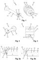
- the connecting fitting 1 shown is used to connect two components, in particular two furniture panels made of chipboard, MDF, wood or the like, and includes a connecting bolt 10 made of metal and a plastic sleeve 20.
- the connecting bolt 10 has a cylindrical bolt shank 11 and at the end a bolt head 12 with a bolt projection 13 projecting radially outwards, for example in the form of a claw or cutting edge.
- the bolt head 12 between the bolt shank 11 and the bolt projection 13 on the side opposite the bolt projection 13 has a latching projection 14 which is preferably convex, in particular spherical or hemispherical.
- the back of the bolt projection 13 facing the bolt shank 11 is designed as a sloping surface 15 , and the bolt side 16 opposite the bolt projection 13 is slanted.
- the bolt shank 11 merges into the bolt head 12 via a step 17 directed radially outward.
- the connecting bolt 10 also has a hemispherical bolt head 18 here.
- the sleeve 20 has a front sleeve opening 21 and inside the sleeve 20 both a sleeve transverse surface 22 directed away from the sleeve opening 21, here inclined, and a locking recess 23 arranged between the sleeve opening 21 and the sleeve transverse surface 22 on the side opposite the sleeve transverse surface 22.
- the latching recess 23 can be formed by a latching trough or, as shown in the exemplary embodiment, by a transverse opening.
- the sleeve transverse surface 22 forms the wall of a lateral sleeve opening 24 which is open on the casing side and which, as shown, can be designed, for example, as a slot which is open on the back can.
- the sleeve 20 is provided with a plurality of barb-like ribs 25 on its outside.
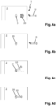
- connection fitting 1 on a furniture panel 2 is shown.
- the sleeve 20 is pressed with the sleeve opening 24 upwards into a bore 3 in the furniture panel 2 ( Figs. 4a, 4b ), whereby the ribs 25 dig into the bore wall.
- the sleeve 20 is preferably additionally glued in the bore 3 .
- the bolt head 12 of the connecting bolt 10 which is tilted at an angle ⁇ (here only by way of example approx. 45°), is inserted by the operator into the socket opening 21 without tools ( Figure 4c ) until the slanted bolt side 16 rests on the opening edge 26 of the socket opening 21.
- the connecting bolt 10 is pressed or tilted downwards by the angle ⁇ into its end position at right angles to the furniture panel 2 ( Figure 4d ), whereby on the one hand the bolt projection 13 with its inclined surface 15 engages behind the inclined transverse surface 22 and on the other hand the inclined bolt side 16 slides further into the socket 20 on the opening edge 26 .
- the tilting movement pulls the bolt head 12 further into the sleeve 20 until the locking projection 14 is locked in the locking recess 23 ( Figs. 5a , 5b ).
- the bolt shank 11 then runs coaxially to the socket axis and thus at right angles to the furniture panel 2, and the step 17 of the connecting bolt 10 is flush with the socket end face.
- a second furniture panel 4 can be fastened to the first furniture panel 2 via the other bolt head 18 .
- the bolt head 12 at its transition to the bolt shank 11 and the socket opening 21 have complementary cross sections, so that the connecting bolt 10 is accommodated in the socket opening 21 without a gap.
- Figure 5a shows the mounted connection fitting 1 with a sleeve 20 that is so narrow that the bolt projection 13 protrudes outwards from the sleeve opening 24 and penetrates into the wall of the bore 3 with its claw-shaped or blade-shaped end. This increases the pull-out values of the connecting bolt 10.
- Figure 5a shows the mounted connection fitting 1 with a socket 20 that is as wide as that the bolt projection 13 does not protrude from the sleeve opening 24 to the outside.
Landscapes
- Engineering & Computer Science (AREA)
- General Engineering & Computer Science (AREA)
- Mechanical Engineering (AREA)
- Connection Of Plates (AREA)
- Furniture Connections (AREA)
Description
- Die Erfindung betrifft einen Verbindungsbeschlag zur Verbindung zweier Teile, insbesondere zweier Möbelplatten aus Span-, MDF- oder holzähnlichen Materialien, gemäß Oberbegriff von Patentanspruch 1. Die Erfindung betrifft weiter eine zugehörige Möbelanordnung mit einem solchen Verbindungsbeschlag.
- Ein derartiger Verbindungsbeschlag ist beispielsweise durch
DE 198 30 740 A1 bekannt geworden. -
DE 198 30 740 A1 dient zur Relingbefestigung für Schubladen und umfasst einen in der Frontblende der Schublade angeordneten Spreizdübel und einen in den Dübel einführbaren Befestigungsbeschlag, der mit einem Relingrohr verbunden ist. Der Befestigungsbeschlag weist ein Kopfteil mit Spreizkopf auf, welcher in den Spreizdübel einführbar ist. Am Kopfteil bzw. Spreizkopf sind Führungen und/oder Rastungen vorgesehen, die mit zugeordneten Nuten bzw. Rastöffnungen des Spreizdübels zusammenwirken. Nach vollständigem Einschieben des Spreizkopfs wird durch Schwenken des Befestigungsbeschlags ein Spreizen des Spreizdübels bewirkt, wodurch die Führungen bzw. Rastungen in entsprechende Sperrstellungen gelangen, so dass der Befestigungsbeschlag sicher im Spreizdübel gehalten wird und ein Herausziehen des Spreizkopfs nicht mehr möglich ist. - Aus
DE 203 12 613 U1 ist ein Anzugsbolzen für einen Beschlag zur lösbaren Verbindung zweier Möbelteile bekannt. Der Anzugsbolzen weist einen in einer ersten Bohrung des ersten Möbelteils anzuordnenden Schaft auf, der mindestens eine sich im Wesentlichen über den halben Umfang des Schafts erstreckende Rippe aufweist. - Aus
DE 295 07 834 U1 ist die Befestigung einer hohlen Relingstange einer Schubladen-Reling an der Frontblende einer Schublade bekannt. Die Frontblende weist im Befestigungsbereich der Relingstange eine in ihrer ins Schubladeninnere weisenden Fläche offen mündende, als Sackbohrung ausgebildete Befestigungsbohrung auf. In die frontblendenzugewandte Stirnseite der Relingstange ist ein Gewindeschaft eines Befestigungsbeschlags eingeschraubt, der einen am Gewindeschaft angesetzten, in die Befestigungsbohrung einführbaren, gegenüber dem Gewindeschaft im Durchmesser vergrößerten Befestigungskopf aufweist. Der Befestigungskopf verjüngt sich von seinem relingstangenseitigen Ende aus in Richtung auf sein freies Ende derart konisch, dass die obere Mantellinie des durch den Befestigungskopf gelegten senkrechten Mittelschnitt vom relingstangenseitigen Ende aus über den größten Teil seiner Länge parallel zur oberen Begrenzungslinie der Relingstange und die untere Mantellinie vom freien Ende des Befestigungskopfs aus über den größten Teil seiner Länge schräg in Abwärtsrichtung verläuft. Im Bereich des freien Endes des Befestigungskopfs ist ein radial nach oben vorspringender, schneidenartig zugeschärfter Vorsprung vorgesehen, dessen Schneide sich in Umfangsrichtung erstreckt -
WO 2018/020097 A1 offenbart einen Möbelkorpus, der aus Platten gebildet ist, welche mittels einer Anordnung aus Nut und Feder zusammengesetzt sind. - In der
DE 20 2018 106 278 U1 wird ein Verbindungsbolzen beschrieben, der mit seinem Bolzenschaft in dem ersten Teil verankert wird. Dann wird der Bolzenkopf mit seinem schneidenförmigen Vorsprung in eine Bohrung des zweiten Teils eingeschwenkt, wodurch der Vorsprung in die Bohrungswandung des zweiten Teils dringt und der Verbindungsbolzen in der Bohrung verankert wird. - Der vorliegenden Erfindung liegt die Aufgabe zugrunde, einen Verbindungsbeschlag der eingangs genannten Art dahingehend weiterzubilden, dass die Verbindungswirkung verbessert wird.
- Die Aufgabe wird erfindungsgemäß durch einen Verbindungsbeschlag mit den Merkmalen von Patentanspruch 1 gelöst.
- Weitere Vorteile der Erfindung ergeben sich aus der Beschreibung, den Ansprüchen und der Zeichnung. Die gezeigten und beschriebenen Ausführungsformen sind nicht als abschließende Aufzählung zu verstehen, sondern haben vielmehr beispielhaften Charakter für die Schilderung der Erfindung.
- Es zeigen:
- Fig. 1
- eine perspektivische Ansicht des erfindungsgemäßen Verbindungsbeschlags mit einem Verbindungsbolzen und mit einer Muffe;
- Fig. 2
- eine andere perspektivische Ansicht des Verbindungsbolzens;
- Fig. 3
- eine Seitenansicht der Muffe;
- Fign. 4a-4d
- die Montage des erfindungsgemäßen Verbindungsbeschlags an einer Möbelwand; und
- Fign. 5a, 5b
- einen Schnitt durch den in
Fig. 4d gezeigten, montierten Verbindungsbeschlag mit einer schmalen Muffe (Fig. 5a ) und mit einer breiten Muffe (Fig. 5b ). - Der in
Fig. 1 gezeigte Verbindungsbeschlag 1 dient zum Verbinden zweier Bauteile, insbesondere zweier Möbelplatten aus Pressspan, MDF, Holz oder ähnlichem, und umfasst einen Verbindungsbolzen 10 aus Metall und eine Kunststoff-Muffe 20. - Der Verbindungsbolzen 10 weist einen zylinderförmigen Bolzenschaft 11 und endseitig einen Bolzenkopf 12 mit einem einen radial nach außen vorstehenden, z.B. krallen- oder schneidenförmigen Bolzenvorsprung 13 auf. Wie in
Fig. 2 gezeigt, weist der Bolzenkopf 12 zwischen Bolzenschaft 11 und Bolzenvorsprung 13 auf der dem Bolzenvorsprung 13 gegenüberliegenden Seite einen Rastvorsprung 14 auf, der bevorzugt konvex, insbesondere kalotten- oder halbkugelförmig ausgebildet ist. Die dem Bolzenschaft 11 zugewandte Rückseite des Bolzenvorsprungs 13 ist als Schrägfläche 15 ausgebildet, und die dem Bolzenvorsprung 13 gegenüberliegende Bolzenseite 16 ist abgeschrägt. Auf der Seite des Bolzenvorsprungs 13 geht der Bolzenschaft 11 über eine radial nach außen gerichtete Stufe 17 in den Bolzenkopf 12 über. An seinem anderen Ende weist der Verbindungsbolzen 10 ebenfalls einen hier halbkugelförmigen Bolzenkopf 18 auf. - Die Muffe 20 weist eine vorderseitige Muffenöffnung 21 und im Innern der Muffe 20 sowohl eine in Richtung fort von der Muffenöffnung 21 gerichtete, hier schräge Muffenquerfläche 22 als auch eine zwischen Muffenöffnung 21 und Muffenquerfläche 22 auf der der Muffenquerfläche 22 gegenüberliegenden Seite angeordnete Rastaussparung 23 auf. Die Rastaussparung 23 kann durch eine Rastmulde oder, wie im Ausführungsbeispiel gezeigt, durch eine Queröffnung gebildet sein. Die Muffenquerfläche 22 bildet die Wand einer mantelseitig offenen, seitlichen Muffenöffnung 24, die wie gezeigt z.B. als ein rückseitig offener Schlitz ausgeführt sein kann. An ihrer Außenseite ist die Muffe 20 mit mehreren widerhakenähnliche Rippen 25 versehen.
- In den
Fign. 4a-4d ist die Montage des Verbindungsbeschlags 1 an einer Möbelplatte 2 gezeigt. - Zunächst wird die Muffe 20, mit der Muffenöffnung 24 nach oben, in eine Bohrung 3 in der Möbelplatte 2 eingepresst (
Fign. 4a, 4b ), wobei sich die Rippen 25 in die Bohrungswand eingraben. Bevorzugt ist die Muffe 20 noch zusätzlich in der Bohrung 3 verleimt. - Dann wird der Bolzenkopf 12 des unter einem Winkel α (hier lediglich beispielhaft ca. 45°) angekippten Verbindungsbolzens 10 vom Bediener werkzeuglos in die Muffenöffnung 21 eingeführt (
Fig. 4c ), bis die abgeschrägte Bolzenseite 16 auf dem Öffnungsrand 26 der Muffenöffnung 21 aufliegt. - Abschließend wird der Verbindungsbolzen 10 um den Winkel α nach unten in seine zur Möbelplatte2 rechtwinklige Endlage gedrückt bzw. verkippt (
Fig. 4d ), wodurch einerseits der Bolzenvorsprung 13 mit seiner Schrägfläche 15 die schräge Querfläche 22 hintergreift und andererseits die abgeschrägte Bolzenseite 16 auf dem Öffnungsrand 26 weiter in die Muffe 20 hineingleitet. Durch die Kippbewegung wird der Bolzenkopf 12 weiter in die Muffe 20 hineingezogen, bis der Rastvorsprung 14 in der Rastaussparung 23 verrastet ist (Fign. 5a, 5b ). Der Bolzenschaft 11 verläuft dann koaxial zur Muffenachse und somit rechtwinklig zur Möbelplatte 2, und die Stufe 17 des Verbindungsbolzens 10 schließt bündig mit der Muffenstirnseite ab. Über den anderen Bolzenkopf 18 kann eine zweite Möbelplatte 4 an der ersten Möbelplatte 2 befestigt werden. Der Bolzenkopf 12 an seinem Übergang zum Bolzenschaft 11 und die Muffenöffnung 21 weisen komplementäre Querschnitte auf, so dass der Verbindungsbolzen 10 spaltfrei in der Muffenöffnung 21 aufgenommen ist. -
Fig. 5a zeigt den montierten Verbindungsbeschlag 1 mit einer so schmalen Muffe 20, dass der Bolzenvorsprung 13 aus der Muffenöffnung 24 nach außen übersteht und mit seinem krallen- oder schneidenförmigen Ende in die Wandung der Bohrung 3 eindringt. Dies erhöht die Auszugswerte des Verbindungsbolzens 10.Fig. 5a zeigt den montierten Verbindungsbeschlag 1 mit einer so breiten Muffe 20, dass der Bolzenvorsprung 13 nicht aus der Muffenöffnung 24 nach außen übersteht.
Claims (10)
- Verbindungsbeschlag (1) aufweisend:- einen Verbindungsbolzen (10) mit einem Bolzenschaft (11) und mit einem Bolzenkopf (12), der einen radial nach außen vorstehenden Bolzenvorsprung (13) und zwischen Bolzenschaft (11) und Bolzenvorsprung (13) auf der dem Bolzenvorsprung (13) gegenüberliegenden Seite einen Rastvorsprung (14) aufweist, wobei die dem Bolzenschaft (11) zugewandte Rückseite des Bolzenvorsprungs (13) als eine in Bezug auf die Längsachse des Bolzenschafts (11) schräg verlaufende Schrägfläche (15) ausgebildet ist, und- eine Muffe (20), die eine vorderseitige Muffenöffnung (21) und im Innern der Muffe (20) sowohl eine in Richtung fort von der Muffenöffnung (21) gerichtete, schräge Muffenquerfläche (22) als auch eine zwischen Muffenöffnung (21) und Muffenquerfläche (22) auf der der schrägen Muffenquerfläche (22) gegenüberliegenden Seite angeordnete Rastaussparung (23) aufweist, wobei die Muffenquerfläche (22) die Wand einer mantelseitig offenen, seitlichen Muffenöffnung (24) bildet,wobei im montierten Zustand des Verbindungsbeschlags (1) der Bolzenkopf (12) in die Muffenöffnung (21) eingeführt ist und sowohl der Bolzenvorsprung (13) mit seiner Schrägfläche (15) die schräge Muffenquerfläche (22) in Einführrichtung des Verbindungsbolzens (10) hintergreift als auch der Rastvorsprung (14) in die Rastaussparung (23) eingerastet ist.
- Verbindungsbeschlag nach Anspruch 1, dadurch gekennzeichnet, dass die Muffenöffnung (21) und der Bolzenkopf (12) am Übergang zum Bolzenschaft (11) komplementäre Querschnitte aufweisen.
- Verbindungsbeschlag nach Anspruch 1 oder 2, dadurch gekennzeichnet, dass im montierten Zustand des Verbindungsbeschlags (1) der Bolzenvorsprung (13) radial nach außen über die Muffe (20) vorsteht.
- Verbindungsbeschlag nach einem der vorhergehenden Ansprüche, dadurch gekennzeichnet, dass auf der Seite des Bolzenvorsprungs (13) der Bolzenschaft (11) über eine radial nach außen gerichtete Stufe (17) in den Bolzenkopf (12) übergeht und im montierten Zustand des Verbindungsbeschlags (1) die Stufe (17) bündig mit der Muffenstirnseite abschließt.
- Verbindungsbeschlag nach einem der vorhergehenden Ansprüche, dadurch gekennzeichnet, dass die Muffe (20) eine sich in radialer Richtung nach außen an die Muffenquerfläche (22) anschließende Öffnung (24) aufweist.
- Verbindungsbeschlag nach einem der vorhergehenden Ansprüche, dadurch gekennzeichnet, dass der Rastvorsprung (14) konvex, insbesondere kalotten- oder halbkugelförmig, ausgebildet ist.
- Verbindungsbeschlag nach einem der vorhergehenden Ansprüche, dadurch gekennzeichnet, dass die dem Bolzenvorsprung (13) gegenüberliegende Bolzenseite (16) abgeschrägt ist.
- Verbindungsbeschlag nach einem der vorhergehenden Ansprüche, dadurch gekennzeichnet, dass auf der Seite des Bolzenvorsprungs (13) der Bolzenschaft (11) über eine radial nach außen gerichtete Stufe (17) in den Bolzenkopf (12) übergeht.
- Möbelanordnung mit zwei Möbelplatten (2, 4) und mit einem Verbindungsbeschlag (1) nach einem der vorhergehenden Ansprüche, wobei die Muffe (20) in einer Bohrung (3) der einen Möbelplatte (2) und der Verbindungsbolzen (10) an der anderen Möbelplatte (4) abgestützt ist.
- Möbelanordnung nach Anspruch 9, dadurch gekennzeichnet, dass der Bolzenvorsprung (13) durch die Muffenöffnung (24) hindurch in die Wandung der Bohrung (3) eingreift.
Applications Claiming Priority (2)
| Application Number | Priority Date | Filing Date | Title |
|---|---|---|---|
| DE202019106842.6U DE202019106842U1 (de) | 2019-12-09 | 2019-12-09 | Verbindungsbolzen und zugehöriger Verbindungsbeschlag |
| PCT/EP2020/084898 WO2021116023A1 (de) | 2019-12-09 | 2020-12-07 | Verbindungsbolzen und zugehöriger verbindungsbeschlag |
Publications (2)
| Publication Number | Publication Date |
|---|---|
| EP4018100A1 EP4018100A1 (de) | 2022-06-29 |
| EP4018100B1 true EP4018100B1 (de) | 2023-08-09 |
Family
ID=69147932
Family Applications (1)
| Application Number | Title | Priority Date | Filing Date |
|---|---|---|---|
| EP20824148.9A Active EP4018100B1 (de) | 2019-12-09 | 2020-12-07 | Verbindungsbeschlag |
Country Status (6)
| Country | Link |
|---|---|
| US (1) | US11512727B2 (de) |
| EP (1) | EP4018100B1 (de) |
| CN (1) | CN114787522B (de) |
| DE (1) | DE202019106842U1 (de) |
| PL (1) | PL4018100T3 (de) |
| WO (1) | WO2021116023A1 (de) |
Families Citing this family (2)
| Publication number | Priority date | Publication date | Assignee | Title |
|---|---|---|---|---|
| DE202021100322U1 (de) | 2021-01-25 | 2021-02-09 | Häfele Berlin Gmbh & Co Kg | Anbindungsbeschlag und zugehörige Anordnung |
| FR3141733B1 (fr) * | 2022-11-09 | 2024-10-25 | Inovame | Système d’assemblage mécanique de type cheville notamment pour la menuiserie |
Family Cites Families (18)
| Publication number | Priority date | Publication date | Assignee | Title |
|---|---|---|---|---|
| US1955353A (en) * | 1931-11-16 | 1934-04-17 | William R Wiley | Bolt |
| US2098997A (en) * | 1935-10-28 | 1937-11-16 | Anderson Co | Stud |
| GB8611689D0 (en) * | 1986-05-13 | 1986-06-18 | Phelps L G | Support system |
| US5069588A (en) * | 1990-09-13 | 1991-12-03 | Illinois Tool Works Inc. | Anchoring device |
| DE29507834U1 (de) * | 1995-05-17 | 1995-07-13 | Mepla-Werke Lautenschläger GmbH & Co KG, 64354 Reinheim | Reling-Befestigungsanordnung an Schubladen |
| DE19703536C1 (de) * | 1997-01-31 | 1998-08-20 | Waterlandse Beheermaatschappij | Vielzweck-Wandhalterung |
| EP0941680A1 (de) * | 1998-03-13 | 1999-09-15 | Fehlbaum & Co. | Tragstangenanordnung für Handels- und Dienstleistungseinrichtungen |
| DE19830740B4 (de) * | 1998-07-09 | 2004-02-19 | Grass Gmbh | Relingbefestigung für Schubladen |
| DE20312613U1 (de) * | 2003-08-14 | 2003-11-06 | Häfele GmbH & Co., 72202 Nagold | Anzugsbolzen |
| DE202005002740U1 (de) * | 2005-02-19 | 2005-06-02 | Visplay International Ag | Vorrichtung zum Aufhängen von Artikeln oder zur Halterung einer Ablage und Aufbau damit |
| DE102010051372B4 (de) | 2010-11-13 | 2012-05-24 | Amer Khodabandeh | Verbindungselement mit integrierter Schnappverbindung |
| DE102011079136A1 (de) * | 2011-07-14 | 2013-01-17 | Robert Bosch Gmbh | Direktsteckelement mit integrierter Verriegelung |
| US8348210B1 (en) * | 2011-11-29 | 2013-01-08 | Chia-Hung Lee | Positioning device for shelves |
| DE202015008847U1 (de) | 2015-12-22 | 2017-03-23 | Grass Gmbh | Befestigungsvorrichtung |
| FR3054419B1 (fr) * | 2016-07-26 | 2018-12-07 | Inovame | Caisson de meuble |
| AT518790B1 (de) * | 2017-02-21 | 2018-01-15 | Blum Gmbh Julius | Verbindungsstift für Möbelteile |
| DE202018106278U1 (de) | 2018-11-05 | 2018-11-16 | Häfele Berlin Gmbh & Co Kg | Verbindungsbolzen zur werkzeuglosen Stoßverbindung zweier Möbelplatten |
| CN109654097A (zh) * | 2019-02-12 | 2019-04-19 | 郑志建 | 一种开放式榫卯结构 |
-
2019
- 2019-12-09 DE DE202019106842.6U patent/DE202019106842U1/de not_active Expired - Lifetime
-
2020
- 2020-12-07 CN CN202080085541.2A patent/CN114787522B/zh active Active
- 2020-12-07 PL PL20824148.9T patent/PL4018100T3/pl unknown
- 2020-12-07 EP EP20824148.9A patent/EP4018100B1/de active Active
- 2020-12-07 WO PCT/EP2020/084898 patent/WO2021116023A1/de not_active Ceased
-
2022
- 2022-06-03 US US17/805,287 patent/US11512727B2/en active Active
Also Published As
| Publication number | Publication date |
|---|---|
| PL4018100T3 (pl) | 2024-02-19 |
| WO2021116023A1 (de) | 2021-06-17 |
| DE202019106842U1 (de) | 2019-12-18 |
| CN114787522B (zh) | 2023-04-18 |
| EP4018100A1 (de) | 2022-06-29 |
| US11512727B2 (en) | 2022-11-29 |
| CN114787522A (zh) | 2022-07-22 |
| US20220290709A1 (en) | 2022-09-15 |
Similar Documents
| Publication | Publication Date | Title |
|---|---|---|
| DE19505311C2 (de) | Befestigungsanordnung von Beschlägen, insbesondere Möbelbeschlägen an Möbelstücken | |
| DE4124727C2 (de) | Befestigungselement mit einer dübelartigen Buchse | |
| EP3585211B1 (de) | Anordnung mit möbelteile und verbindungsstift | |
| EP3184828B1 (de) | Befestigungsvorrichtung | |
| DE19527600C5 (de) | Möbelbeschlag | |
| DE202016008130U1 (de) | Verbindungsvorrichtung zwischen den Komponenten eines Möbels | |
| EP2145133B1 (de) | Befestigungsvorrichtung zur befestigung von gegenständen an einer grundfläche | |
| EP3821142A1 (de) | VERBINDUNGSBOLZEN ZUR WERKZEUGLOSEN STOßVERBINDUNG ZWEIER MÖBELPLATTEN | |
| EP3692267B1 (de) | Verbinder zum stossverbinden zweier bauteile | |
| EP3404151A1 (de) | Vorrichtung zum befestigen eines sanitärgegenstandes und verwendung einer solchen vorrichtung | |
| WO1996014513A1 (de) | Verbindungsbeschlag | |
| DE602004005630T2 (de) | Schraubdübel | |
| EP3962325B1 (de) | Wandhaken, befestigungsanordnung mit dem wandhaken und verfahren zum befestigen des wandhakens | |
| EP4018100A1 (de) | Verbindungsbolzen und zugehöriger verbindungsbeschlag | |
| EP3404152A1 (de) | Befestigungsset zum befestigen eines montagegestells für sanitärobjekte und verwendung eines solchen befestigungssets | |
| DE20312075U1 (de) | Vorrichtung mit zwei durch eine Verbindungsschraube zusammengehaltenen Hohlprofilen sowie Werkzeug dazu | |
| WO2018162090A1 (de) | Spannverbinder und befestigungsanordnung mit einem solchen | |
| EP3388691B1 (de) | Rückwandverbinder | |
| DE102022102238B4 (de) | Wandbauteil für eine Schublade, Schublade und Möbel | |
| EP1134170B1 (de) | Modulartig zusammensetzbare Struktur für Lagerregale | |
| EP4569236A1 (de) | Verbindungsbeschlag sowie zugehörige anordnung mit zwei miteinander verbundenen komponenten | |
| DE102010055808A1 (de) | Befestigungsvorrichtung | |
| WO2008080703A2 (de) | Verbindungsbeschlag zum verbinden zweier möbelplatten | |
| DE20300574U1 (de) | Verbindungsbeschlag für Möbel-Bauteile | |
| EP3269903B1 (de) | Rosettengarnitur für drücker bei türen oder fenstern |
Legal Events
| Date | Code | Title | Description |
|---|---|---|---|
| STAA | Information on the status of an ep patent application or granted ep patent |
Free format text: STATUS: UNKNOWN |
|
| STAA | Information on the status of an ep patent application or granted ep patent |
Free format text: STATUS: THE INTERNATIONAL PUBLICATION HAS BEEN MADE |
|
| PUAI | Public reference made under article 153(3) epc to a published international application that has entered the european phase |
Free format text: ORIGINAL CODE: 0009012 |
|
| STAA | Information on the status of an ep patent application or granted ep patent |
Free format text: STATUS: REQUEST FOR EXAMINATION WAS MADE |
|
| 17P | Request for examination filed |
Effective date: 20220323 |
|
| AK | Designated contracting states |
Kind code of ref document: A1 Designated state(s): AL AT BE BG CH CY CZ DE DK EE ES FI FR GB GR HR HU IE IS IT LI LT LU LV MC MK MT NL NO PL PT RO RS SE SI SK SM TR |
|
| DAV | Request for validation of the european patent (deleted) | ||
| DAX | Request for extension of the european patent (deleted) | ||
| GRAP | Despatch of communication of intention to grant a patent |
Free format text: ORIGINAL CODE: EPIDOSNIGR1 |
|
| STAA | Information on the status of an ep patent application or granted ep patent |
Free format text: STATUS: GRANT OF PATENT IS INTENDED |
|
| INTG | Intention to grant announced |
Effective date: 20230327 |
|
| GRAS | Grant fee paid |
Free format text: ORIGINAL CODE: EPIDOSNIGR3 |
|
| GRAA | (expected) grant |
Free format text: ORIGINAL CODE: 0009210 |
|
| STAA | Information on the status of an ep patent application or granted ep patent |
Free format text: STATUS: THE PATENT HAS BEEN GRANTED |
|
| AK | Designated contracting states |
Kind code of ref document: B1 Designated state(s): AL AT BE BG CH CY CZ DE DK EE ES FI FR GB GR HR HU IE IS IT LI LT LU LV MC MK MT NL NO PL PT RO RS SE SI SK SM TR |
|
| P01 | Opt-out of the competence of the unified patent court (upc) registered |
Effective date: 20230630 |
|
| REG | Reference to a national code |
Ref country code: GB Ref legal event code: FG4D Free format text: NOT ENGLISH |
|
| REG | Reference to a national code |
Ref country code: CH Ref legal event code: EP |
|
| REG | Reference to a national code |
Ref country code: DE Ref legal event code: R096 Ref document number: 502020004678 Country of ref document: DE |
|
| REG | Reference to a national code |
Ref country code: IE Ref legal event code: FG4D Free format text: LANGUAGE OF EP DOCUMENT: GERMAN |
|
| REG | Reference to a national code |
Ref country code: LT Ref legal event code: MG9D |
|
| REG | Reference to a national code |
Ref country code: NL Ref legal event code: MP Effective date: 20230809 |
|
| PG25 | Lapsed in a contracting state [announced via postgrant information from national office to epo] |
Ref country code: GR Free format text: LAPSE BECAUSE OF FAILURE TO SUBMIT A TRANSLATION OF THE DESCRIPTION OR TO PAY THE FEE WITHIN THE PRESCRIBED TIME-LIMIT Effective date: 20231110 |
|
| PG25 | Lapsed in a contracting state [announced via postgrant information from national office to epo] |
Ref country code: IS Free format text: LAPSE BECAUSE OF FAILURE TO SUBMIT A TRANSLATION OF THE DESCRIPTION OR TO PAY THE FEE WITHIN THE PRESCRIBED TIME-LIMIT Effective date: 20231209 |
|
| PG25 | Lapsed in a contracting state [announced via postgrant information from national office to epo] |
Ref country code: SE Free format text: LAPSE BECAUSE OF FAILURE TO SUBMIT A TRANSLATION OF THE DESCRIPTION OR TO PAY THE FEE WITHIN THE PRESCRIBED TIME-LIMIT Effective date: 20230809 Ref country code: RS Free format text: LAPSE BECAUSE OF FAILURE TO SUBMIT A TRANSLATION OF THE DESCRIPTION OR TO PAY THE FEE WITHIN THE PRESCRIBED TIME-LIMIT Effective date: 20230809 Ref country code: PT Free format text: LAPSE BECAUSE OF FAILURE TO SUBMIT A TRANSLATION OF THE DESCRIPTION OR TO PAY THE FEE WITHIN THE PRESCRIBED TIME-LIMIT Effective date: 20231211 Ref country code: NO Free format text: LAPSE BECAUSE OF FAILURE TO SUBMIT A TRANSLATION OF THE DESCRIPTION OR TO PAY THE FEE WITHIN THE PRESCRIBED TIME-LIMIT Effective date: 20231109 Ref country code: NL Free format text: LAPSE BECAUSE OF FAILURE TO SUBMIT A TRANSLATION OF THE DESCRIPTION OR TO PAY THE FEE WITHIN THE PRESCRIBED TIME-LIMIT Effective date: 20230809 Ref country code: LV Free format text: LAPSE BECAUSE OF FAILURE TO SUBMIT A TRANSLATION OF THE DESCRIPTION OR TO PAY THE FEE WITHIN THE PRESCRIBED TIME-LIMIT Effective date: 20230809 Ref country code: LT Free format text: LAPSE BECAUSE OF FAILURE TO SUBMIT A TRANSLATION OF THE DESCRIPTION OR TO PAY THE FEE WITHIN THE PRESCRIBED TIME-LIMIT Effective date: 20230809 Ref country code: IS Free format text: LAPSE BECAUSE OF FAILURE TO SUBMIT A TRANSLATION OF THE DESCRIPTION OR TO PAY THE FEE WITHIN THE PRESCRIBED TIME-LIMIT Effective date: 20231209 Ref country code: HR Free format text: LAPSE BECAUSE OF FAILURE TO SUBMIT A TRANSLATION OF THE DESCRIPTION OR TO PAY THE FEE WITHIN THE PRESCRIBED TIME-LIMIT Effective date: 20230809 Ref country code: GR Free format text: LAPSE BECAUSE OF FAILURE TO SUBMIT A TRANSLATION OF THE DESCRIPTION OR TO PAY THE FEE WITHIN THE PRESCRIBED TIME-LIMIT Effective date: 20231110 Ref country code: FI Free format text: LAPSE BECAUSE OF FAILURE TO SUBMIT A TRANSLATION OF THE DESCRIPTION OR TO PAY THE FEE WITHIN THE PRESCRIBED TIME-LIMIT Effective date: 20230809 |
|
| PG25 | Lapsed in a contracting state [announced via postgrant information from national office to epo] |
Ref country code: ES Free format text: LAPSE BECAUSE OF FAILURE TO SUBMIT A TRANSLATION OF THE DESCRIPTION OR TO PAY THE FEE WITHIN THE PRESCRIBED TIME-LIMIT Effective date: 20230809 |
|
| PG25 | Lapsed in a contracting state [announced via postgrant information from national office to epo] |
Ref country code: SM Free format text: LAPSE BECAUSE OF FAILURE TO SUBMIT A TRANSLATION OF THE DESCRIPTION OR TO PAY THE FEE WITHIN THE PRESCRIBED TIME-LIMIT Effective date: 20230809 Ref country code: RO Free format text: LAPSE BECAUSE OF FAILURE TO SUBMIT A TRANSLATION OF THE DESCRIPTION OR TO PAY THE FEE WITHIN THE PRESCRIBED TIME-LIMIT Effective date: 20230809 Ref country code: ES Free format text: LAPSE BECAUSE OF FAILURE TO SUBMIT A TRANSLATION OF THE DESCRIPTION OR TO PAY THE FEE WITHIN THE PRESCRIBED TIME-LIMIT Effective date: 20230809 Ref country code: EE Free format text: LAPSE BECAUSE OF FAILURE TO SUBMIT A TRANSLATION OF THE DESCRIPTION OR TO PAY THE FEE WITHIN THE PRESCRIBED TIME-LIMIT Effective date: 20230809 Ref country code: DK Free format text: LAPSE BECAUSE OF FAILURE TO SUBMIT A TRANSLATION OF THE DESCRIPTION OR TO PAY THE FEE WITHIN THE PRESCRIBED TIME-LIMIT Effective date: 20230809 Ref country code: CZ Free format text: LAPSE BECAUSE OF FAILURE TO SUBMIT A TRANSLATION OF THE DESCRIPTION OR TO PAY THE FEE WITHIN THE PRESCRIBED TIME-LIMIT Effective date: 20230809 Ref country code: SK Free format text: LAPSE BECAUSE OF FAILURE TO SUBMIT A TRANSLATION OF THE DESCRIPTION OR TO PAY THE FEE WITHIN THE PRESCRIBED TIME-LIMIT Effective date: 20230809 |
|
| REG | Reference to a national code |
Ref country code: DE Ref legal event code: R097 Ref document number: 502020004678 Country of ref document: DE |
|
| PG25 | Lapsed in a contracting state [announced via postgrant information from national office to epo] |
Ref country code: IT Free format text: LAPSE BECAUSE OF FAILURE TO SUBMIT A TRANSLATION OF THE DESCRIPTION OR TO PAY THE FEE WITHIN THE PRESCRIBED TIME-LIMIT Effective date: 20230809 |
|
| PLBE | No opposition filed within time limit |
Free format text: ORIGINAL CODE: 0009261 |
|
| STAA | Information on the status of an ep patent application or granted ep patent |
Free format text: STATUS: NO OPPOSITION FILED WITHIN TIME LIMIT |
|
| 26N | No opposition filed |
Effective date: 20240513 |
|
| PG25 | Lapsed in a contracting state [announced via postgrant information from national office to epo] |
Ref country code: SI Free format text: LAPSE BECAUSE OF FAILURE TO SUBMIT A TRANSLATION OF THE DESCRIPTION OR TO PAY THE FEE WITHIN THE PRESCRIBED TIME-LIMIT Effective date: 20230809 |
|
| REG | Reference to a national code |
Ref country code: CH Ref legal event code: PL |
|
| PG25 | Lapsed in a contracting state [announced via postgrant information from national office to epo] |
Ref country code: LU Free format text: LAPSE BECAUSE OF NON-PAYMENT OF DUE FEES Effective date: 20231207 |
|
| PG25 | Lapsed in a contracting state [announced via postgrant information from national office to epo] |
Ref country code: MC Free format text: LAPSE BECAUSE OF FAILURE TO SUBMIT A TRANSLATION OF THE DESCRIPTION OR TO PAY THE FEE WITHIN THE PRESCRIBED TIME-LIMIT Effective date: 20230809 |
|
| REG | Reference to a national code |
Ref country code: BE Ref legal event code: MM Effective date: 20231231 |
|
| PG25 | Lapsed in a contracting state [announced via postgrant information from national office to epo] |
Ref country code: MC Free format text: LAPSE BECAUSE OF FAILURE TO SUBMIT A TRANSLATION OF THE DESCRIPTION OR TO PAY THE FEE WITHIN THE PRESCRIBED TIME-LIMIT Effective date: 20230809 Ref country code: LU Free format text: LAPSE BECAUSE OF NON-PAYMENT OF DUE FEES Effective date: 20231207 |
|
| REG | Reference to a national code |
Ref country code: IE Ref legal event code: MM4A |
|
| PG25 | Lapsed in a contracting state [announced via postgrant information from national office to epo] |
Ref country code: IE Free format text: LAPSE BECAUSE OF NON-PAYMENT OF DUE FEES Effective date: 20231207 |
|
| PG25 | Lapsed in a contracting state [announced via postgrant information from national office to epo] |
Ref country code: BE Free format text: LAPSE BECAUSE OF NON-PAYMENT OF DUE FEES Effective date: 20231231 |
|
| PG25 | Lapsed in a contracting state [announced via postgrant information from national office to epo] |
Ref country code: FR Free format text: LAPSE BECAUSE OF NON-PAYMENT OF DUE FEES Effective date: 20231231 |
|
| PG25 | Lapsed in a contracting state [announced via postgrant information from national office to epo] |
Ref country code: CH Free format text: LAPSE BECAUSE OF NON-PAYMENT OF DUE FEES Effective date: 20231231 |
|
| PG25 | Lapsed in a contracting state [announced via postgrant information from national office to epo] |
Ref country code: IE Free format text: LAPSE BECAUSE OF NON-PAYMENT OF DUE FEES Effective date: 20231207 Ref country code: FR Free format text: LAPSE BECAUSE OF NON-PAYMENT OF DUE FEES Effective date: 20231231 Ref country code: CH Free format text: LAPSE BECAUSE OF NON-PAYMENT OF DUE FEES Effective date: 20231231 Ref country code: BE Free format text: LAPSE BECAUSE OF NON-PAYMENT OF DUE FEES Effective date: 20231231 |
|
| PG25 | Lapsed in a contracting state [announced via postgrant information from national office to epo] |
Ref country code: BG Free format text: LAPSE BECAUSE OF FAILURE TO SUBMIT A TRANSLATION OF THE DESCRIPTION OR TO PAY THE FEE WITHIN THE PRESCRIBED TIME-LIMIT Effective date: 20230809 |
|
| PG25 | Lapsed in a contracting state [announced via postgrant information from national office to epo] |
Ref country code: BG Free format text: LAPSE BECAUSE OF FAILURE TO SUBMIT A TRANSLATION OF THE DESCRIPTION OR TO PAY THE FEE WITHIN THE PRESCRIBED TIME-LIMIT Effective date: 20230809 |
|
| PGFP | Annual fee paid to national office [announced via postgrant information from national office to epo] |
Ref country code: TR Payment date: 20241127 Year of fee payment: 5 |
|
| PG25 | Lapsed in a contracting state [announced via postgrant information from national office to epo] |
Ref country code: CY Free format text: LAPSE BECAUSE OF FAILURE TO SUBMIT A TRANSLATION OF THE DESCRIPTION OR TO PAY THE FEE WITHIN THE PRESCRIBED TIME-LIMIT; INVALID AB INITIO Effective date: 20201207 |
|
| PG25 | Lapsed in a contracting state [announced via postgrant information from national office to epo] |
Ref country code: HU Free format text: LAPSE BECAUSE OF FAILURE TO SUBMIT A TRANSLATION OF THE DESCRIPTION OR TO PAY THE FEE WITHIN THE PRESCRIBED TIME-LIMIT; INVALID AB INITIO Effective date: 20201207 |
|
| GBPC | Gb: european patent ceased through non-payment of renewal fee |
Effective date: 20241207 |
|
| PG25 | Lapsed in a contracting state [announced via postgrant information from national office to epo] |
Ref country code: GB Free format text: LAPSE BECAUSE OF NON-PAYMENT OF DUE FEES Effective date: 20241207 |
|
| PGFP | Annual fee paid to national office [announced via postgrant information from national office to epo] |
Ref country code: AT Payment date: 20260113 Year of fee payment: 5 |
|
| PGFP | Annual fee paid to national office [announced via postgrant information from national office to epo] |
Ref country code: PL Payment date: 20251121 Year of fee payment: 6 |
|
| PGFP | Annual fee paid to national office [announced via postgrant information from national office to epo] |
Ref country code: DE Payment date: 20251218 Year of fee payment: 6 |