EP4018082B1 - A refiner device for refining of a liquid - Google Patents
A refiner device for refining of a liquid Download PDFInfo
- Publication number
- EP4018082B1 EP4018082B1 EP20835725.1A EP20835725A EP4018082B1 EP 4018082 B1 EP4018082 B1 EP 4018082B1 EP 20835725 A EP20835725 A EP 20835725A EP 4018082 B1 EP4018082 B1 EP 4018082B1
- Authority
- EP
- European Patent Office
- Prior art keywords
- liquid
- air
- receiving plate
- liquid receiving
- refiner
- Prior art date
- Legal status (The legal status is an assumption and is not a legal conclusion. Google has not performed a legal analysis and makes no representation as to the accuracy of the status listed.)
- Active
Links
Images

Classifications
-
- F—MECHANICAL ENGINEERING; LIGHTING; HEATING; WEAPONS; BLASTING
- F01—MACHINES OR ENGINES IN GENERAL; ENGINE PLANTS IN GENERAL; STEAM ENGINES
- F01M—LUBRICATING OF MACHINES OR ENGINES IN GENERAL; LUBRICATING INTERNAL COMBUSTION ENGINES; CRANKCASE VENTILATING
- F01M1/00—Pressure lubrication
- F01M1/10—Lubricating systems characterised by the provision therein of lubricant venting or purifying means, e.g. of filters
-
- B—PERFORMING OPERATIONS; TRANSPORTING
- B01—PHYSICAL OR CHEMICAL PROCESSES OR APPARATUS IN GENERAL
- B01D—SEPARATION
- B01D3/00—Distillation or related exchange processes in which liquids are contacted with gaseous media, e.g. stripping
- B01D3/34—Distillation or related exchange processes in which liquids are contacted with gaseous media, e.g. stripping with one or more auxiliary substances
- B01D3/343—Distillation or related exchange processes in which liquids are contacted with gaseous media, e.g. stripping with one or more auxiliary substances the substance being a gas
- B01D3/346—Distillation or related exchange processes in which liquids are contacted with gaseous media, e.g. stripping with one or more auxiliary substances the substance being a gas the gas being used for removing vapours, e.g. transport gas
-
- B—PERFORMING OPERATIONS; TRANSPORTING
- B01—PHYSICAL OR CHEMICAL PROCESSES OR APPARATUS IN GENERAL
- B01D—SEPARATION
- B01D1/00—Evaporating
- B01D1/0011—Heating features
-
- B—PERFORMING OPERATIONS; TRANSPORTING
- B01—PHYSICAL OR CHEMICAL PROCESSES OR APPARATUS IN GENERAL
- B01D—SEPARATION
- B01D1/00—Evaporating
- B01D1/22—Evaporating by bringing a thin layer of the liquid into contact with a heated surface
-
- B—PERFORMING OPERATIONS; TRANSPORTING
- B01—PHYSICAL OR CHEMICAL PROCESSES OR APPARATUS IN GENERAL
- B01D—SEPARATION
- B01D1/00—Evaporating
- B01D1/22—Evaporating by bringing a thin layer of the liquid into contact with a heated surface
- B01D1/222—In rotating vessels; vessels with movable parts
-
- B—PERFORMING OPERATIONS; TRANSPORTING
- B01—PHYSICAL OR CHEMICAL PROCESSES OR APPARATUS IN GENERAL
- B01D—SEPARATION
- B01D3/00—Distillation or related exchange processes in which liquids are contacted with gaseous media, e.g. stripping
- B01D3/34—Distillation or related exchange processes in which liquids are contacted with gaseous media, e.g. stripping with one or more auxiliary substances
- B01D3/343—Distillation or related exchange processes in which liquids are contacted with gaseous media, e.g. stripping with one or more auxiliary substances the substance being a gas
-
- F—MECHANICAL ENGINEERING; LIGHTING; HEATING; WEAPONS; BLASTING
- F01—MACHINES OR ENGINES IN GENERAL; ENGINE PLANTS IN GENERAL; STEAM ENGINES
- F01M—LUBRICATING OF MACHINES OR ENGINES IN GENERAL; LUBRICATING INTERNAL COMBUSTION ENGINES; CRANKCASE VENTILATING
- F01M5/00—Heating, cooling, or controlling temperature of lubricant; Lubrication means facilitating engine starting
- F01M5/001—Heating
-
- F—MECHANICAL ENGINEERING; LIGHTING; HEATING; WEAPONS; BLASTING
- F02—COMBUSTION ENGINES; HOT-GAS OR COMBUSTION-PRODUCT ENGINE PLANTS
- F02M—SUPPLYING COMBUSTION ENGINES IN GENERAL WITH COMBUSTIBLE MIXTURES OR CONSTITUENTS THEREOF
- F02M37/00—Apparatus or systems for feeding liquid fuel from storage containers to carburettors or fuel-injection apparatus; Arrangements for purifying liquid fuel specially adapted for, or arranged on, internal-combustion engines
- F02M37/22—Arrangements for purifying liquid fuel specially adapted for, or arranged on, internal-combustion engines, e.g. arrangements in the feeding system
- F02M37/30—Arrangements for purifying liquid fuel specially adapted for, or arranged on, internal-combustion engines, e.g. arrangements in the feeding system characterised by heating means
-
- F—MECHANICAL ENGINEERING; LIGHTING; HEATING; WEAPONS; BLASTING
- F02—COMBUSTION ENGINES; HOT-GAS OR COMBUSTION-PRODUCT ENGINE PLANTS
- F02M—SUPPLYING COMBUSTION ENGINES IN GENERAL WITH COMBUSTIBLE MIXTURES OR CONSTITUENTS THEREOF
- F02M37/00—Apparatus or systems for feeding liquid fuel from storage containers to carburettors or fuel-injection apparatus; Arrangements for purifying liquid fuel specially adapted for, or arranged on, internal-combustion engines
- F02M37/22—Arrangements for purifying liquid fuel specially adapted for, or arranged on, internal-combustion engines, e.g. arrangements in the feeding system
- F02M37/32—Arrangements for purifying liquid fuel specially adapted for, or arranged on, internal-combustion engines, e.g. arrangements in the feeding system characterised by filters or filter arrangements
- F02M37/38—Arrangements for purifying liquid fuel specially adapted for, or arranged on, internal-combustion engines, e.g. arrangements in the feeding system characterised by filters or filter arrangements with regeneration means
-
- F—MECHANICAL ENGINEERING; LIGHTING; HEATING; WEAPONS; BLASTING
- F16—ENGINEERING ELEMENTS AND UNITS; GENERAL MEASURES FOR PRODUCING AND MAINTAINING EFFECTIVE FUNCTIONING OF MACHINES OR INSTALLATIONS; THERMAL INSULATION IN GENERAL
- F16N—LUBRICATING
- F16N39/00—Arrangements for conditioning of lubricants in the lubricating system
- F16N39/002—Arrangements for conditioning of lubricants in the lubricating system by deaeration
-
- F—MECHANICAL ENGINEERING; LIGHTING; HEATING; WEAPONS; BLASTING
- F16—ENGINEERING ELEMENTS AND UNITS; GENERAL MEASURES FOR PRODUCING AND MAINTAINING EFFECTIVE FUNCTIONING OF MACHINES OR INSTALLATIONS; THERMAL INSULATION IN GENERAL
- F16N—LUBRICATING
- F16N39/00—Arrangements for conditioning of lubricants in the lubricating system
- F16N39/005—Arrangements for conditioning of lubricants in the lubricating system by evaporating or purifying
-
- F—MECHANICAL ENGINEERING; LIGHTING; HEATING; WEAPONS; BLASTING
- F16—ENGINEERING ELEMENTS AND UNITS; GENERAL MEASURES FOR PRODUCING AND MAINTAINING EFFECTIVE FUNCTIONING OF MACHINES OR INSTALLATIONS; THERMAL INSULATION IN GENERAL
- F16N—LUBRICATING
- F16N39/00—Arrangements for conditioning of lubricants in the lubricating system
- F16N39/04—Arrangements for conditioning of lubricants in the lubricating system by heating
-
- F—MECHANICAL ENGINEERING; LIGHTING; HEATING; WEAPONS; BLASTING
- F24—HEATING; RANGES; VENTILATING
- F24H—FLUID HEATERS, e.g. WATER OR AIR HEATERS, HAVING HEAT-GENERATING MEANS, e.g. HEAT PUMPS, IN GENERAL
- F24H1/00—Water heaters, e.g. boilers, continuous-flow heaters or water-storage heaters
- F24H1/0018—Water heaters, e.g. boilers, continuous-flow heaters or water-storage heaters using electric energy supply
-
- F—MECHANICAL ENGINEERING; LIGHTING; HEATING; WEAPONS; BLASTING
- F01—MACHINES OR ENGINES IN GENERAL; ENGINE PLANTS IN GENERAL; STEAM ENGINES
- F01M—LUBRICATING OF MACHINES OR ENGINES IN GENERAL; LUBRICATING INTERNAL COMBUSTION ENGINES; CRANKCASE VENTILATING
- F01M1/00—Pressure lubrication
- F01M1/10—Lubricating systems characterised by the provision therein of lubricant venting or purifying means, e.g. of filters
- F01M2001/1007—Lubricating systems characterised by the provision therein of lubricant venting or purifying means, e.g. of filters characterised by the purification means combined with other functions
- F01M2001/1021—Lubricating systems characterised by the provision therein of lubricant venting or purifying means, e.g. of filters characterised by the purification means combined with other functions comprising self cleaning systems
-
- F—MECHANICAL ENGINEERING; LIGHTING; HEATING; WEAPONS; BLASTING
- F02—COMBUSTION ENGINES; HOT-GAS OR COMBUSTION-PRODUCT ENGINE PLANTS
- F02M—SUPPLYING COMBUSTION ENGINES IN GENERAL WITH COMBUSTIBLE MIXTURES OR CONSTITUENTS THEREOF
- F02M31/00—Apparatus for thermally treating combustion-air, fuel, or fuel-air mixture
- F02M31/02—Apparatus for thermally treating combustion-air, fuel, or fuel-air mixture for heating
- F02M31/16—Other apparatus for heating fuel
- F02M31/18—Other apparatus for heating fuel to vaporise fuel
- F02M31/186—Other apparatus for heating fuel to vaporise fuel with simultaneous mixing of secondary air
-
- F—MECHANICAL ENGINEERING; LIGHTING; HEATING; WEAPONS; BLASTING
- F24—HEATING; RANGES; VENTILATING
- F24H—FLUID HEATERS, e.g. WATER OR AIR HEATERS, HAVING HEAT-GENERATING MEANS, e.g. HEAT PUMPS, IN GENERAL
- F24H2250/00—Electrical heat generating means
- F24H2250/04—Positive temperature coefficients [PTC]; Negative temperature coefficients [NTC]
Definitions
- the device may include a particle filter that initially cleans the oil from particles and a liquid separation part intended for separating liquid in the form of water and fuel from the particle free oil.
- the liquid separation part can be provided in several different ways, e.g. as a substantially dome shaped heating plate.
- the heat plate may typically be shaped and arranged so that the oil remains on the heating plate for a certain period of time. In this manner, the complete oil film is brought to a temperature, by the heating plate, where the liquid can evaporate from the oil which remains on the plate.
- Another problem relates to the fact that the outdoor temperature often differs in different climates and in different parts of the world, which affects the temperature of the oil entering the liquid separation part. Cold conditions give colder oil and further energy is therefore required in order for the oil to reach the right temperature. Warm conditions, on the other hand, give warmer oil requiring the heat from the heat plate to be regulated to compensate the heat increase in order for the oil not to reach too high temperature.
- a properly working regulating arrangement for the heat plate is thus necessary for making the system work properly.
- Such a regulating arrangement comprises thermostats and other regulators comprising moving parts which in this context is a possible cause for malfunction, causing limited useful life and often undesired high oil temperatures. Such a regulating arrangement is also expensive and hard to install.
- WO2017093470A1 discloses an oil refinery device where oil or fuel is fed to a heated plate arranged in a housing and where air is fed to and from the housing so as to transport away contaminates evaporated from the oil or fuel.
- the plate is heated by point heat sources.
- US2785109A discloses a refiner device according to the pre-amble of claim 1.
- An object of this invention is to provide a refinery device that exhibit an improved refinery efficiency compared to conventional refinery devices, but that still provides for easy installation and use in existing systems. This object is achieved by the device defined by the technical features contained in claim 1.
- the dependent claims contain advantageous embodiments, further developments and variants of the invention.
- the invention concerns a refiner device for refining of a liquid, such as oil or fuel
- the refiner device comprises a housing provided with a liquid inlet for unrefined oil or fuel, a liquid outlet for refined oil or fuel, an air inlet for supplying a flow of air into the housing, and an air outlet for discharging air and contaminants removed from the liquid.
- the refiner device further comprises a liquid receiving plate arranged inside the housing, wherein the refiner device is arranged such that when liquid has passed through the liquid inlet during operation of the device, the liquid is contacted with an upper side of the liquid receiving plate before it reaches the liquid outlet.
- the refiner device further comprises at least one heating element arranged to directly or indirectly heat the liquid while the liquid is in contact with the liquid receiving plate.
- the refiner device may be of the type exemplified in, for instance, WO2017093470A1 where unrefined oil or fuel liquid is deposited onto and allowed to flow over a substantially horizontal, or at least not too inclined, heated plate or similar before it flows further down to an outlet.
- the expression "the liquid is contacted with an upper side of the liquid receiving plate” thus relates to the situation when the device has been properly oriented for being operated.
- the at least one air passage thus provides a flow communication between the air outlet inside the hollow air-guiding member and the air inlet outside of said member. And the air passage is arranged in association with the liquid receiving plate so as to force the air flow closer to the plate.
- An advantageous effect of such a design is that the air flow, preferably the entire air flow, is forced to pass closer to the heated liquid located on the liquid receiving plate on its way towards the air outlet. This makes the transfer of (evaporated) contaminants from the liquid to the air much more efficient compared to e.g. the device of WO2017093470A1 where the air flow is not forced to pass along the plate but instead can take almost any path inside the housing from the air inlet to the air outlet and thus might pass through the housing without coming into contact with the heated liquid.
- the device is arranged so that liquid that enters the housing via the liquid inlet during operation of the device is deposited onto a first point of the liquid receiving plate and so that the deposited liquid flows upon the liquid receiving plate in a direction towards a second point of the liquid receiving plate, and wherein the at least one air passage is arranged at the second point of the liquid receiving plate so as to, during operation of the device, force air to flow in a general direction towards the first point of the liquid receiving plate, i.e. in a direction generally opposite to that of the liquid flow.
- a main effect of such an embodiment is that a counter-current flow is obtained at the liquid receiving plate during operation of the device in that the liquid flows on the plate in one direction and the air flows above the plate in the opposite direction.
- a counter-current flow further increases the transfer of contaminants from the liquid to the air flow and thus further increases the refining efficiency.
- a counter-current flow of this type can be obtained by directing the incoming liquid towards a certain point of the liquid receiving plate, adapting the plate so that the liquid flows from that point in a certain direction, such as towards an edge of the plate, and locating the air passage leading into the hollow air-guiding member so that the air flows in the opposite direction in relation to the liquid.
- the liquid receiving plate may have another shape than a circular disc, and the air passage(s) may have another design.
- the liquid receiving plate may have a rectangular shape, in which case the liquid may be deposited at a first end of the plate and the air passage may be arranged at a second opposite end of the plate (where the device is arranged so that the liquid flows from the first to the second end of the plate during operation).
- the hollow air-guiding member comprises a funnel shaped element having a wide side and an opposite narrow side, wherein the funnel shaped element is arranged at the liquid receiving plate with its wide side facing the liquid receiving plate.
- a funnel shaped air-guiding member is well adapted for a liquid receiving plate have the shape of a circular disc.
- the at least one air passage is distributed around a perimeter of the liquid receiving plate.
- the air passage may be a single opening that extends along the perimeter or a plurality of openings distributed along the perimeter. Such a plurality of openings may or may not be evenly distributed along the perimeter depending on the design of the liquid receiving plate.
- liquid receiving plate and the hollow air-guiding member are separate components arranged at a distance from each other, wherein said distance forms the at least one air passage.
- the plate and the air-guiding member may or may not be connected directly to each other.
- liquid inlet is arranged inside of the hollow air-guiding member. This facilitates depositing the liquid properly onto the liquid receiving plate.
- liquid inlet thus here refers to the position where the liquid is introduced into the housing of the device, i.e. "the outlet of the liquid inlet”.
- the at least one heating element is a PTC ceramic element.
- PTC elements positive thermal coefficient of resistance
- PTC ceramic heating elements are well known as such.
- the at least one heating element is arranged to heat the liquid receiving plate.
- the heating element(s) thus heat(s) the liquid indirectly, via the plate.
- the device comprises a plurality of distributed heating elements. This provides for an even distribution of the temperature, in particular where the heating elements heat the liquid receiving plate (that in turn heats the liquid).
- the device comprises an air flow control system configured to control supply and/or quality of the air fed to the air inlet during operation of the device. In most applications it is important to control the mass flow rate of the air properly.
- the control system may also control e.g. pre-drying of the air.
- the liquid inlet is arranged in an upper part of the housing.
- the liquid outlet is arranged in a lower part of the housing. The liquid may thus flow through the device downwardly using only gravity as the driving force.
- the refiner device 1 comprises a housing 2 provided with a liquid inlet 3 for unrefined oil or fuel, a liquid outlet 4 for refined oil or fuel, an air inlet 5 for supplying a flow of air into the housing 2, and an air outlet 6 for discharging air and contaminants removed from the liquid.
- the liquid outlet 4 is arranged on a lower side 2b of the housing 2, whereas the air outlet 6 and the two inlets 3, 5 are arranged on an upper side 2a of the housing 2.
- An electric connection 25 for supplying electric power to heating elements 9 arranged inside the housing 2 is also provided on the upper side 2a of the housing 2.
- the electric connection 25 is also arranged to provide for control of the heating elements 9.
- the liquid receiving plate 7 and the funnel shaped element 10 are connected to each other by means of screws 13 and nuts 14.
- Distance elements 15 are provided between the liquid receiving plate 7 and the funnel shaped element 10 so as to create the annular air passage 11.
Landscapes
- Engineering & Computer Science (AREA)
- General Engineering & Computer Science (AREA)
- Mechanical Engineering (AREA)
- Chemical & Material Sciences (AREA)
- Chemical Kinetics & Catalysis (AREA)
- Combustion & Propulsion (AREA)
- Physics & Mathematics (AREA)
- Thermal Sciences (AREA)
- Vaporization, Distillation, Condensation, Sublimation, And Cold Traps (AREA)
- Production Of Liquid Hydrocarbon Mixture For Refining Petroleum (AREA)
- Physical Or Chemical Processes And Apparatus (AREA)
Description
- This invention relates to a refiner device for refining of a liquid, such as oil or fuel, according to the preamble of claim 1.
- Operation of internal combustion engines and hydraulic-mechanical devices involves the use of lubricating oil and hydraulic oil, respectively. Further, internal combustion engines are usually powered by energy-dense liquid fuel such as e.g. mineral fuel, petrol, diesel oil, i.e. liquids derived from fossil fuels, and/or bio fuels. Such oil and fuel liquids get contaminated and needs to be refined.
- When the internal combustion engine is operated, the lubricating oil becomes contaminated with non-combusted fuel, water, cooling agents such as glycol and/or substances from the fuel combustion. Hydraulic oil is generally not subject to any combustion process but becomes typically contaminated in a similar way as lubrication oil. In these types of applications, the oil absorbs water from air humidity and condensation in the tank, or from water penetrating the system at change-overs or when cleaning. Thus, there is a desire to refine or clean the oil from unwanted substances without replacing the oil in the device.
- In some oil cleaning devices the device may include a particle filter that initially cleans the oil from particles and a liquid separation part intended for separating liquid in the form of water and fuel from the particle free oil. The liquid separation part can be provided in several different ways, e.g. as a substantially dome shaped heating plate. The heat plate may typically be shaped and arranged so that the oil remains on the heating plate for a certain period of time. In this manner, the complete oil film is brought to a temperature, by the heating plate, where the liquid can evaporate from the oil which remains on the plate.
-
US8377263B2 discloses one example of a device for regenerating oil, in which the device comprises a heat source, a support substrate and a transportation device. This type of device is based on the principle of heating e.g. hydraulic oil within a period of time to ensure that an appropriate level of evaporation of water can occur at a high flow rate. This device thus makes use of the fact that oil and water have different boiling temperatures. - Another problem relates to the fact that the outdoor temperature often differs in different climates and in different parts of the world, which affects the temperature of the oil entering the liquid separation part. Cold conditions give colder oil and further energy is therefore required in order for the oil to reach the right temperature. Warm conditions, on the other hand, give warmer oil requiring the heat from the heat plate to be regulated to compensate the heat increase in order for the oil not to reach too high temperature. A properly working regulating arrangement for the heat plate is thus necessary for making the system work properly. Such a regulating arrangement comprises thermostats and other regulators comprising moving parts which in this context is a possible cause for malfunction, causing limited useful life and often undesired high oil temperatures. Such a regulating arrangement is also expensive and hard to install.
-
WO2017093470A1 discloses an oil refinery device where oil or fuel is fed to a heated plate arranged in a housing and where air is fed to and from the housing so as to transport away contaminates evaporated from the oil or fuel. The plate is heated by point heat sources. - Although the device of
WO2017093470A1 appears to provide for relatively efficient refining and easy installation and use in existing systems such as industrial applications, hydraulic applications or the like, there is still a need for improvements. -
US2785109A discloses a refiner device according to the pre-amble of claim 1. - An object of this invention is to provide a refinery device that exhibit an improved refinery efficiency compared to conventional refinery devices, but that still provides for easy installation and use in existing systems. This object is achieved by the device defined by the technical features contained in claim 1. The dependent claims contain advantageous embodiments, further developments and variants of the invention.
- The invention concerns a refiner device for refining of a liquid, such as oil or fuel, wherein the refiner device comprises a housing provided with a liquid inlet for unrefined oil or fuel, a liquid outlet for refined oil or fuel, an air inlet for supplying a flow of air into the housing, and an air outlet for discharging air and contaminants removed from the liquid. The refiner device further comprises a liquid receiving plate arranged inside the housing, wherein the refiner device is arranged such that when liquid has passed through the liquid inlet during operation of the device, the liquid is contacted with an upper side of the liquid receiving plate before it reaches the liquid outlet. The refiner device further comprises at least one heating element arranged to directly or indirectly heat the liquid while the liquid is in contact with the liquid receiving plate.
- The refiner device may be of the type exemplified in, for instance,
WO2017093470A1 where unrefined oil or fuel liquid is deposited onto and allowed to flow over a substantially horizontal, or at least not too inclined, heated plate or similar before it flows further down to an outlet. The expression "the liquid is contacted with an upper side of the liquid receiving plate" thus relates to the situation when the device has been properly oriented for being operated. - The invention is characterized in that the refiner device comprises a hollow air-guiding member arranged at the liquid receiving plate, wherein the hollow air-guiding member has an open side facing the upper surface of the liquid receiving plate, wherein the air inlet is located outside of the hollow air-guiding member, wherein the air outlet is located inside of the hollow air-guiding member, wherein at least one air passage into the hollow air-guiding member is arranged at the liquid receiving plate so as to, when air is fed through the housing from the air inlet to the air outlet, force air to flow along at least a part of the liquid receiving plate when passing through the air passage and/or when flowing further into the hollow air-guiding member towards the air outlet.
- The at least one air passage thus provides a flow communication between the air outlet inside the hollow air-guiding member and the air inlet outside of said member. And the air passage is arranged in association with the liquid receiving plate so as to force the air flow closer to the plate.
- An advantageous effect of such a design is that the air flow, preferably the entire air flow, is forced to pass closer to the heated liquid located on the liquid receiving plate on its way towards the air outlet. This makes the transfer of (evaporated) contaminants from the liquid to the air much more efficient compared to e.g. the device of
WO2017093470A1 where the air flow is not forced to pass along the plate but instead can take almost any path inside the housing from the air inlet to the air outlet and thus might pass through the housing without coming into contact with the heated liquid. - In an embodiment the device is arranged so that liquid that enters the housing via the liquid inlet during operation of the device is deposited onto a first point of the liquid receiving plate and so that the deposited liquid flows upon the liquid receiving plate in a direction towards a second point of the liquid receiving plate, and wherein the at least one air passage is arranged at the second point of the liquid receiving plate so as to, during operation of the device, force air to flow in a general direction towards the first point of the liquid receiving plate, i.e. in a direction generally opposite to that of the liquid flow.
- A main effect of such an embodiment is that a counter-current flow is obtained at the liquid receiving plate during operation of the device in that the liquid flows on the plate in one direction and the air flows above the plate in the opposite direction. Such a counter-current flow further increases the transfer of contaminants from the liquid to the air flow and thus further increases the refining efficiency.
- A counter-current flow of this type can be obtained by directing the incoming liquid towards a certain point of the liquid receiving plate, adapting the plate so that the liquid flows from that point in a certain direction, such as towards an edge of the plate, and locating the air passage leading into the hollow air-guiding member so that the air flows in the opposite direction in relation to the liquid.
- In an embodiment, the first point (at which incoming unrefined liquid is deposited onto the liquid receiving plate) is a central point of the liquid receiving plate, wherein the device is arranged so that the liquid deposited onto the first, central point flows radially outwards from the first, central point towards a perimeter of the liquid receiving plate, wherein the second point is located at said perimeter. The air passage leading into the hollow air-guiding member may in such a case have the form of an opening that extends along the perimeter edge of the plate (or have the form of a plurality of openings distributed along said perimeter edge). If the liquid receiving plate is a circular disc the air passage may thus have the form of an annular opening (or have the form of a plurality of openings distributed along the circumference of the circular plate).
- In other embodiments the liquid receiving plate may have another shape than a circular disc, and the air passage(s) may have another design. In one embodiment the liquid receiving plate may have a rectangular shape, in which case the liquid may be deposited at a first end of the plate and the air passage may be arranged at a second opposite end of the plate (where the device is arranged so that the liquid flows from the first to the second end of the plate during operation).
- In an embodiment the hollow air-guiding member comprises a funnel shaped element having a wide side and an opposite narrow side, wherein the funnel shaped element is arranged at the liquid receiving plate with its wide side facing the liquid receiving plate. Such a funnel shaped air-guiding member is well adapted for a liquid receiving plate have the shape of a circular disc.
- In an embodiment the at least one air passage is distributed around a perimeter of the liquid receiving plate. As mentioned above, this means that the air passage may be a single opening that extends along the perimeter or a plurality of openings distributed along the perimeter. Such a plurality of openings may or may not be evenly distributed along the perimeter depending on the design of the liquid receiving plate.
- In an embodiment the liquid receiving plate and the hollow air-guiding member are separate components arranged at a distance from each other, wherein said distance forms the at least one air passage. In such a case the plate and the air-guiding member may or may not be connected directly to each other.
- In an embodiment the liquid inlet is arranged inside of the hollow air-guiding member. This facilitates depositing the liquid properly onto the liquid receiving plate. The term "liquid inlet" thus here refers to the position where the liquid is introduced into the housing of the device, i.e. "the outlet of the liquid inlet".
- In an embodiment the at least one heating element is a PTC ceramic element. PTC elements (positive thermal coefficient of resistance) are suitable for heating as they can be controlled properly. It is important to keep the temperature within a set interval during operation of the device since a too low temperature leads to a poor refining efficiency and since a too high temperature may deteriorate the oil or fuel to be refined. Which temperature to be used depends on the particular application. PTC ceramic heating elements are well known as such.
- In an embodiment the at least one heating element is arranged to heat the liquid receiving plate. The heating element(s) thus heat(s) the liquid indirectly, via the plate.
- In an embodiment the device comprises a plurality of distributed heating elements. This provides for an even distribution of the temperature, in particular where the heating elements heat the liquid receiving plate (that in turn heats the liquid).
- In an embodiment the device comprises an air flow control system configured to control supply and/or quality of the air fed to the air inlet during operation of the device. In most applications it is important to control the mass flow rate of the air properly. The control system may also control e.g. pre-drying of the air.
- In an embodiment the liquid inlet is arranged in an upper part of the housing. Preferably, the liquid outlet is arranged in a lower part of the housing. The liquid may thus flow through the device downwardly using only gravity as the driving force.
- In the description of the invention given below reference is made to the following figure, in which:
-
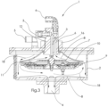
Figure 1 shows, in a perspective view, an example embodiment of a refiner device according to this disclosure. -
Figure 2 shows, in a side view, the embodiment offigure 1 . -
Figure 3 shows, in a sectional view, the embodiment offigure 1 . -
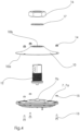
Figure 4 shows, in an exploded view, some parts of the embodiment offig. 1 . -
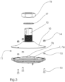
Figure 5 shows the parts offigure 4 in another exploded view. - An example embodiment of a refiner device 1 for refining of a liquid, such as oil or fuel, will now be described with reference to
figures 1-5 . - The refiner device 1 comprises a
housing 2 provided with aliquid inlet 3 for unrefined oil or fuel, aliquid outlet 4 for refined oil or fuel, anair inlet 5 for supplying a flow of air into thehousing 2, and an air outlet 6 for discharging air and contaminants removed from the liquid. Theliquid outlet 4 is arranged on alower side 2b of thehousing 2, whereas the air outlet 6 and the twoinlets upper side 2a of thehousing 2. Anelectric connection 25 for supplying electric power to heating elements 9 arranged inside thehousing 2 is also provided on theupper side 2a of thehousing 2. Theelectric connection 25 is also arranged to provide for control of the heating elements 9. - The refiner device 1 further comprises a liquid receiving plate 7 arranged inside the
housing 2. The refiner device 1 is arranged such that when liquid (solid arrows 8 infigure 3 ) has passed through theliquid inlet 3 during operation of the device 1, theliquid 8 is contacted with an upper side 7a (seefigures 4 and5 ) of the liquid receiving plate 7 before it flows over an circumferential edge of the liquid receiving plate 7 downwards a bottom of thehousing 2 and reaches theliquid outlet 4. The liquid receiving plate 7 has in this example the general shape of a circular disc. - The device 1 is arranged so that liquid that enters the
housing 2 via theliquid inlet 3 during operation of the device 1 is deposited onto afirst point 7b of the liquid receiving plate 7. In this case thisfirst point 7b is a central point of the circular liquid receiving plate 7. A dome shaped part is arranged at thiscentral point 7b. Liquid deposited onto this first,central point 7b will then flow upon the liquid receiving plate 7 radially outwards in a direction towards a second point of the liquid receiving plate 7, wherein this second point in this example is a perimeter or edge of the liquid receiving plate 7. Anair passage 11 is arranged along the edge of the liquid receiving plate 7 (see further explanation below). - The refiner device 1 further comprises a plurality of heating elements in the form of controllable PTC ceramic elements 9 arranged under and adjacent to an outer, lower section of the liquid receiving plate 7. The heating elements 9 are arranged to heat the liquid receiving plate 7 and thus to indirectly heat the
liquid 8 while the liquid is in contact with, i.e. flows over, the liquid receiving plate 7. - The refiner device 1 further comprises a hollow air-guiding
member 10 arranged at the liquid receiving plate 7. In this example the hollow air-guiding member has the general form of a funnel shapedelement 10 having a wide, open,lower side 10a and an opposite narrow,upper side 10b (seefigure 4 ). The funnel shapedelement 10 is arranged at the liquid receiving plate 7 with its wide,open side 10a facing downwards towards the upper surface 7a of the liquid receiving plate 7. The hollow air-guiding member/funnel shapedelement 10 is in this example circular and the size and shape of the wide,open side 10a generally corresponds to the size and shape of the liquid receiving plate 7. - A
component 12 comprising ducts forming part of theliquid inlet 3 and the air outlet 6 is arranged at the narrow,upper side 10b of the funnel shapedelement 10. - As shown in
figure 3 , theair inlet 5 is located outside of the hollow air-guiding member/funnel shapedelement 10, i.e. the air fed to the device 1 enters thehousing 2 outside of the hollow air-guiding member/funnel shapedelement 10. As further shown infigure 3 , the air outlet 6 is located inside of the hollow air-guiding member/funnel shaped element 10 (in the component 12), which means that air (and contaminants) that is fed away from the device 1 exits thehousing 2 inside of the hollow air-guiding member/funnel shapedelement 10. - Besides the air outlet 6, also the
liquid inlet 3 is arranged inside of the hollow air-guiding member/funnel shaped element 10 (in the component 12), i.e. unrefined liquid that is fed to the device 1 enters thehousing 2 inside of the hollow air-guiding member/funnel shapedelement 10. - The
air passage 11 mentioned above is arranged at the liquid receiving plate 7 and is arranged to allow air to flow into the hollow air-guiding member/funnel shapedelement 10 is. In this example theair passage 11 has the form of an annular opening extending between the outer perimeters of the lower,wide side 10a of the funnel shapedelement 10 and of the (upper surface 7a of the) liquid receiving plate 7. The liquid receiving plate 7 and the hollow air-guiding member/funnel shapedelement 10 are here separate components arranged at a distance from each other, and this distance forms theannular air passage 11. - As shown in
figures 3-5 , the liquid receiving plate 7 and the funnel shapedelement 10 are connected to each other by means ofscrews 13 and nuts 14. Distanceelements 15 are provided between the liquid receiving plate 7 and the funnel shapedelement 10 so as to create theannular air passage 11. - The
component 12 fits into an opening in thenarrow side 10b of the funnel shapedelement 10 has a flange at its lower side that fits below a corresponding flange of the funnel shapedelement 10 so as to hold the funnel shaped element 10 (and the liquid receiving plate 7 connected thereto) in place. The lower side of thecomponent 12 closes thenarrow side 10b of the funnel shapedelement 10. An upper portion of thecomponent 12 protrudes through an opening in theupper side 2a of thehousing 2 and is connected to theupper side 2a of thehousing 2 by means of a nut 16 (and a washer 17) arranged on the outer,upper side 2a of thehousing 2, wherein thenut 16 is threaded onto threads arranged on thecomponent 12. - When air is fed through the
housing 2 from theair inlet 5 to the air outlet 6, the air (see dashedarrows 18 infigure 3 ) is forced to flow through theannular air passage 11 radially inwards along at least a part of the liquid receiving plate 7 when passing through theair passage 11 and flowing further into the hollow air-guidingmember 10 towards the air outlet 6. Since the oil or fuel liquid flows in the opposite radial direction over the liquid receiving plate 7 a counter-current flow is created between the (heated)liquid flow 8 and theair flow 18. Besides that the air is forced to flow close the surface of the liquid, the air is thus forced to create a counter-current flow. Together this provides for a very efficient transfer of (evaporated) contaminants from the liquid to the air and thus for a very efficient refining of the liquid. - The refiner device 1 further comprises an air flow control system (not shown) configured to control supply (mass flow rate) of the air fed to the
air inlet 5 during operation of the device 1. The air flow control system also comprises a drying unit for drying air fed to the device 1 in order to further increase transfer of water (vapour) from the liquid to the air. - The invention is not limited by the embodiments described above but can be modified in various ways within the scope of the claims. For instance, the liquid receiving plate 7 may have another shape than a circular disc and the incoming liquid does not necessarily have to be deposited onto a centrally located point of the liquid receiving plate 7. Moreover, the hollow
air guiding member 10 does not necessarily have to comprise a funnel shaped element but can have another shape.
Claims (13)
- A refiner device (1) for refining of a liquid, such as oil or fuel, wherein the refiner device comprises a housing (2) provided with a liquid inlet (3) for unrefined oil or fuel, a liquid outlet (4) for refined oil or fuel, an air inlet (5) for supplying a flow of air into the housing, and an air outlet (6) for discharging air and contaminants removed from the liquid,wherein the refiner device (1) further comprises a liquid receiving plate (7) arranged inside the housing (2),wherein the refiner device (1) is arranged such that when liquid has passed through the liquid inlet (3) during operation of the device, the liquid is contacted with an upper surface (7a) of the liquid receiving plate (7) before it reaches the liquid outlet (4),wherein the refiner device (1) further comprises at least one heating element (9) arranged to directly or indirectly heat the liquid while the liquid is in contact with the liquid receiving plate (7),characterized inthat the refiner device (1) comprises a hollow air-guiding member (10) arranged at the liquid receiving plate (7),wherein the hollow air-guiding member (10) has an open side (10a) facing the upper surface (7a) of the liquid receiving plate (7),wherein the air inlet (5) is located outside of the hollow air-guiding member (10),wherein the air outlet (6) is located inside of the hollow air-guiding member (10),wherein at least one air passage (11) into the hollow air-guiding member (10) is arranged at the liquid receiving plate (7) so as to, when air is fed through the housing (2) from the air inlet (5) to the air outlet (6), force air to flow along at least a part of the liquid receiving plate (7) when passing through the air passage (11) and/or when flowing further into the hollow air-guiding member (10) towards the air outlet (6).
- The refiner device according to claim 1, wherein the device is arranged so that liquid that enters the housing via the liquid inlet during operation of the device is deposited onto a first point of the liquid receiving plate and so that the deposited liquid flows upon the liquid receiving plate in a direction towards a second point of the liquid receiving plate, and wherein the at least one air passage is arranged at the second point of the liquid receiving plate so as to, during operation of the device, force air to flow in a general direction towards the first point of the liquid receiving plate, i.e. in a direction generally opposite to that of the liquid flow.
- The refiner device according to claim 2, wherein the first point is a central point of the liquid receiving plate, wherein the device is arranged so that the liquid deposited onto the first, central point flows radially outwards from the first, central point towards a perimeter, wherein the second point is located at said perimeter.
- The refiner device according to any of the above claims, wherein the hollow air-guiding member comprises a funnel shaped element having a wide side and an opposite narrow side, wherein the funnel shaped element is arranged at the liquid receiving plate with its wide side facing the liquid receiving plate.
- The refiner device according to any of the above claims, wherein the at least one air passage is distributed around a perimeter of the liquid receiving plate.
- The refiner device according to any of the above claims, wherein the liquid receiving plate and the hollow air-guiding member are separate components arranged at a distance from each other, wherein said distance forms the at least one air passage.
- The refiner device according to any of the above claims, wherein the liquid inlet is arranged inside of the hollow air-guiding member.
- The refiner device according to any of the above claims, wherein the at least one heating element is a PTC ceramic element.
- The refiner device according to any of the above claims, wherein the at least one heating element is arranged to heat the liquid receiving plate.
- The refiner device according to any of the above claims, wherein the device comprises a plurality of distributed heating elements.
- The refiner device according to any of the above claims, wherein the device comprises an air flow control system configured to control supply and/or quality of the air fed to the air inlet during operation of the device.
- The refiner device according to any of the above claims, wherein the liquid inlet is arranged in an upper part of the housing.
- The refiner device according to any of the above claims, wherein the liquid outlet is arranged in a lower part of the housing.
Applications Claiming Priority (2)
| Application Number | Priority Date | Filing Date | Title |
|---|---|---|---|
| SE2050467 | 2020-04-24 | ||
| PCT/EP2020/086240 WO2021213694A1 (en) | 2020-04-24 | 2020-12-15 | A refiner device for refining of a liquid |
Publications (3)
| Publication Number | Publication Date |
|---|---|
| EP4018082A1 EP4018082A1 (en) | 2022-06-29 |
| EP4018082B1 true EP4018082B1 (en) | 2024-05-22 |
| EP4018082C0 EP4018082C0 (en) | 2024-05-22 |
Family
ID=74125163
Family Applications (1)
| Application Number | Title | Priority Date | Filing Date |
|---|---|---|---|
| EP20835725.1A Active EP4018082B1 (en) | 2020-04-24 | 2020-12-15 | A refiner device for refining of a liquid |
Country Status (6)
| Country | Link |
|---|---|
| US (1) | US11969676B2 (en) |
| EP (1) | EP4018082B1 (en) |
| CA (1) | CA3184346A1 (en) |
| CL (1) | CL2022000863A1 (en) |
| PL (1) | PL4018082T3 (en) |
| WO (1) | WO2021213694A1 (en) |
Family Cites Families (13)
| Publication number | Priority date | Publication date | Assignee | Title |
|---|---|---|---|---|
| US2307954A (en) | 1941-07-28 | 1943-01-12 | John T Radke | Magnetic oil cleaner |
| US2785109A (en) * | 1955-03-14 | 1957-03-12 | William C Schwalge | Oil reclaimer |
| US3771656A (en) * | 1972-02-28 | 1973-11-13 | R Leaming | Oil cleaning device for automotive engines |
| DE3739929A1 (en) * | 1987-11-25 | 1989-06-08 | Geier Henninger Kurt | Oil-sulphur cooling boiler OCB |
| US7244353B2 (en) | 2002-11-15 | 2007-07-17 | Oil Purification Systems, Inc. | Method of and system for fluid purification |
| SE527777C2 (en) | 2005-10-10 | 2006-06-07 | Cot Clean Oil Techology Ab | Oil purification device for e.g. vehicle engine oil contaminated with water, contains spot heat source for heating contaminant |
| US7976702B2 (en) * | 2007-11-30 | 2011-07-12 | Next Generation Filtration Systems, Lp | Fluid purification systems and methods |
| US8318023B2 (en) * | 2009-09-28 | 2012-11-27 | GM Global Technology Operations LLC | Heated air assisted membrane separation of water and fuel from engine oil in an internal combustion engine |
| US9988956B2 (en) | 2011-01-14 | 2018-06-05 | New Jersey Institute Of Technology | System and method for continuous removal of water from oil via membrane separation |
| US9995433B2 (en) * | 2012-02-27 | 2018-06-12 | John Arthur Harris | Oil cleaner with heated evaporation surface, to remove water and volatiles |
| SE1551594A1 (en) | 2015-12-04 | 2017-06-05 | Cot-Clean Oil Tech Ab | Refiner device for oil or fuel and system |
| KR20180075814A (en) * | 2016-12-27 | 2018-07-05 | 한화케미칼 주식회사 | distillation |
| US10619793B2 (en) | 2018-04-06 | 2020-04-14 | John Ostgaard | Oil conditioner for removing fluid impurities |
-
2020
- 2020-12-15 EP EP20835725.1A patent/EP4018082B1/en active Active
- 2020-12-15 CA CA3184346A patent/CA3184346A1/en active Pending
- 2020-12-15 PL PL20835725.1T patent/PL4018082T3/en unknown
- 2020-12-15 WO PCT/EP2020/086240 patent/WO2021213694A1/en not_active Ceased
- 2020-12-15 US US17/769,500 patent/US11969676B2/en active Active
-
2022
- 2022-04-05 CL CL2022000863A patent/CL2022000863A1/en unknown
Also Published As
| Publication number | Publication date |
|---|---|
| US11969676B2 (en) | 2024-04-30 |
| US20230330558A1 (en) | 2023-10-19 |
| CA3184346A1 (en) | 2021-10-28 |
| PL4018082T3 (en) | 2024-09-09 |
| EP4018082A1 (en) | 2022-06-29 |
| CL2022000863A1 (en) | 2022-11-11 |
| EP4018082C0 (en) | 2024-05-22 |
| WO2021213694A1 (en) | 2021-10-28 |
Similar Documents
| Publication | Publication Date | Title |
|---|---|---|
| US4372260A (en) | Engine fluid heater | |
| US4676895A (en) | Fluid flow baffle for fuel processor | |
| EP0168160B1 (en) | Filter block mounted fuel processor apparatus | |
| US5855772A (en) | Fuel filter and water separator apparatus with heater | |
| US4006084A (en) | Oil reclaiming device | |
| US4289583A (en) | Oil reclamation device | |
| US5242034A (en) | Oil reclamation device | |
| US4338907A (en) | Gasoline fume generator and mixer | |
| US20120006725A1 (en) | Device for regeneration of oils | |
| EP4018082B1 (en) | A refiner device for refining of a liquid | |
| US6818046B1 (en) | Liquid purifying device | |
| EP1807167B1 (en) | Reclamation unit for a liquid including a filter unit and a heating unit | |
| CN102438720B (en) | Fluid reforming system | |
| WO2017093470A1 (en) | Refiner device for oil or fuel and refiner device assembly | |
| WO1996025996A2 (en) | An oil recycler | |
| RU2285867C1 (en) | Plenum chamber of conditioner with rotor heat exchanger | |
| CA1183744A (en) | Engine fluid heater | |
| US20100084255A1 (en) | Liquid purifying device | |
| MX2008004646A (en) | Device for regeneration of oils | |
| HU192281B (en) | Oil filtering and regenerating device for internal combustion engines |
Legal Events
| Date | Code | Title | Description |
|---|---|---|---|
| STAA | Information on the status of an ep patent application or granted ep patent |
Free format text: STATUS: UNKNOWN |
|
| STAA | Information on the status of an ep patent application or granted ep patent |
Free format text: STATUS: THE INTERNATIONAL PUBLICATION HAS BEEN MADE |
|
| PUAI | Public reference made under article 153(3) epc to a published international application that has entered the european phase |
Free format text: ORIGINAL CODE: 0009012 |
|
| STAA | Information on the status of an ep patent application or granted ep patent |
Free format text: STATUS: REQUEST FOR EXAMINATION WAS MADE |
|
| 17P | Request for examination filed |
Effective date: 20220325 |
|
| AK | Designated contracting states |
Kind code of ref document: A1 Designated state(s): AL AT BE BG CH CY CZ DE DK EE ES FI FR GB GR HR HU IE IS IT LI LT LU LV MC MK MT NL NO PL PT RO RS SE SI SK SM TR |
|
| DAV | Request for validation of the european patent (deleted) | ||
| DAX | Request for extension of the european patent (deleted) | ||
| GRAP | Despatch of communication of intention to grant a patent |
Free format text: ORIGINAL CODE: EPIDOSNIGR1 |
|
| STAA | Information on the status of an ep patent application or granted ep patent |
Free format text: STATUS: GRANT OF PATENT IS INTENDED |
|
| INTG | Intention to grant announced |
Effective date: 20231113 |
|
| GRAJ | Information related to disapproval of communication of intention to grant by the applicant or resumption of examination proceedings by the epo deleted |
Free format text: ORIGINAL CODE: EPIDOSDIGR1 |
|
| STAA | Information on the status of an ep patent application or granted ep patent |
Free format text: STATUS: REQUEST FOR EXAMINATION WAS MADE |
|
| INTC | Intention to grant announced (deleted) | ||
| GRAP | Despatch of communication of intention to grant a patent |
Free format text: ORIGINAL CODE: EPIDOSNIGR1 |
|
| STAA | Information on the status of an ep patent application or granted ep patent |
Free format text: STATUS: GRANT OF PATENT IS INTENDED |
|
| INTG | Intention to grant announced |
Effective date: 20240219 |
|
| GRAS | Grant fee paid |
Free format text: ORIGINAL CODE: EPIDOSNIGR3 |
|
| GRAA | (expected) grant |
Free format text: ORIGINAL CODE: 0009210 |
|
| STAA | Information on the status of an ep patent application or granted ep patent |
Free format text: STATUS: THE PATENT HAS BEEN GRANTED |
|
| AK | Designated contracting states |
Kind code of ref document: B1 Designated state(s): AL AT BE BG CH CY CZ DE DK EE ES FI FR GB GR HR HU IE IS IT LI LT LU LV MC MK MT NL NO PL PT RO RS SE SI SK SM TR |
|
| REG | Reference to a national code |
Ref country code: GB Ref legal event code: FG4D |
|
| REG | Reference to a national code |
Ref country code: CH Ref legal event code: EP |
|
| REG | Reference to a national code |
Ref country code: DE Ref legal event code: R096 Ref document number: 602020031403 Country of ref document: DE |
|
| REG | Reference to a national code |
Ref country code: IE Ref legal event code: FG4D |
|
| U01 | Request for unitary effect filed |
Effective date: 20240605 |
|
| U07 | Unitary effect registered |
Designated state(s): AT BE BG DE DK EE FI FR IT LT LU LV MT NL PT SE SI Effective date: 20240620 |
|
| PG25 | Lapsed in a contracting state [announced via postgrant information from national office to epo] |
Ref country code: IS Free format text: LAPSE BECAUSE OF FAILURE TO SUBMIT A TRANSLATION OF THE DESCRIPTION OR TO PAY THE FEE WITHIN THE PRESCRIBED TIME-LIMIT Effective date: 20240922 |
|
| PG25 | Lapsed in a contracting state [announced via postgrant information from national office to epo] |
Ref country code: HR Free format text: LAPSE BECAUSE OF FAILURE TO SUBMIT A TRANSLATION OF THE DESCRIPTION OR TO PAY THE FEE WITHIN THE PRESCRIBED TIME-LIMIT Effective date: 20240522 |
|
| PG25 | Lapsed in a contracting state [announced via postgrant information from national office to epo] |
Ref country code: GR Free format text: LAPSE BECAUSE OF FAILURE TO SUBMIT A TRANSLATION OF THE DESCRIPTION OR TO PAY THE FEE WITHIN THE PRESCRIBED TIME-LIMIT Effective date: 20240823 |
|
| PG25 | Lapsed in a contracting state [announced via postgrant information from national office to epo] |
Ref country code: ES Free format text: LAPSE BECAUSE OF FAILURE TO SUBMIT A TRANSLATION OF THE DESCRIPTION OR TO PAY THE FEE WITHIN THE PRESCRIBED TIME-LIMIT Effective date: 20240522 |
|
| PG25 | Lapsed in a contracting state [announced via postgrant information from national office to epo] |
Ref country code: IS Free format text: LAPSE BECAUSE OF FAILURE TO SUBMIT A TRANSLATION OF THE DESCRIPTION OR TO PAY THE FEE WITHIN THE PRESCRIBED TIME-LIMIT Effective date: 20240922 Ref country code: HR Free format text: LAPSE BECAUSE OF FAILURE TO SUBMIT A TRANSLATION OF THE DESCRIPTION OR TO PAY THE FEE WITHIN THE PRESCRIBED TIME-LIMIT Effective date: 20240522 Ref country code: GR Free format text: LAPSE BECAUSE OF FAILURE TO SUBMIT A TRANSLATION OF THE DESCRIPTION OR TO PAY THE FEE WITHIN THE PRESCRIBED TIME-LIMIT Effective date: 20240823 Ref country code: ES Free format text: LAPSE BECAUSE OF FAILURE TO SUBMIT A TRANSLATION OF THE DESCRIPTION OR TO PAY THE FEE WITHIN THE PRESCRIBED TIME-LIMIT Effective date: 20240522 Ref country code: RS Free format text: LAPSE BECAUSE OF FAILURE TO SUBMIT A TRANSLATION OF THE DESCRIPTION OR TO PAY THE FEE WITHIN THE PRESCRIBED TIME-LIMIT Effective date: 20240822 |
|
| U20 | Renewal fee for the european patent with unitary effect paid |
Year of fee payment: 5 Effective date: 20241028 |
|
| PG25 | Lapsed in a contracting state [announced via postgrant information from national office to epo] |
Ref country code: CZ Free format text: LAPSE BECAUSE OF FAILURE TO SUBMIT A TRANSLATION OF THE DESCRIPTION OR TO PAY THE FEE WITHIN THE PRESCRIBED TIME-LIMIT Effective date: 20240522 |
|
| PG25 | Lapsed in a contracting state [announced via postgrant information from national office to epo] |
Ref country code: SK Free format text: LAPSE BECAUSE OF FAILURE TO SUBMIT A TRANSLATION OF THE DESCRIPTION OR TO PAY THE FEE WITHIN THE PRESCRIBED TIME-LIMIT Effective date: 20240522 Ref country code: RO Free format text: LAPSE BECAUSE OF FAILURE TO SUBMIT A TRANSLATION OF THE DESCRIPTION OR TO PAY THE FEE WITHIN THE PRESCRIBED TIME-LIMIT Effective date: 20240522 |
|
| PG25 | Lapsed in a contracting state [announced via postgrant information from national office to epo] |
Ref country code: SK Free format text: LAPSE BECAUSE OF FAILURE TO SUBMIT A TRANSLATION OF THE DESCRIPTION OR TO PAY THE FEE WITHIN THE PRESCRIBED TIME-LIMIT Effective date: 20240522 Ref country code: RO Free format text: LAPSE BECAUSE OF FAILURE TO SUBMIT A TRANSLATION OF THE DESCRIPTION OR TO PAY THE FEE WITHIN THE PRESCRIBED TIME-LIMIT Effective date: 20240522 Ref country code: CZ Free format text: LAPSE BECAUSE OF FAILURE TO SUBMIT A TRANSLATION OF THE DESCRIPTION OR TO PAY THE FEE WITHIN THE PRESCRIBED TIME-LIMIT Effective date: 20240522 |
|
| REG | Reference to a national code |
Ref country code: DE Ref legal event code: R097 Ref document number: 602020031403 Country of ref document: DE |
|
| PLBE | No opposition filed within time limit |
Free format text: ORIGINAL CODE: 0009261 |
|
| STAA | Information on the status of an ep patent application or granted ep patent |
Free format text: STATUS: NO OPPOSITION FILED WITHIN TIME LIMIT |
|
| 26N | No opposition filed |
Effective date: 20250225 |
|
| PG25 | Lapsed in a contracting state [announced via postgrant information from national office to epo] |
Ref country code: MC Free format text: LAPSE BECAUSE OF FAILURE TO SUBMIT A TRANSLATION OF THE DESCRIPTION OR TO PAY THE FEE WITHIN THE PRESCRIBED TIME-LIMIT Effective date: 20240522 |
|
| REG | Reference to a national code |
Ref country code: CH Ref legal event code: PL |
|
| PG25 | Lapsed in a contracting state [announced via postgrant information from national office to epo] |
Ref country code: CH Free format text: LAPSE BECAUSE OF NON-PAYMENT OF DUE FEES Effective date: 20241231 |
|
| PG25 | Lapsed in a contracting state [announced via postgrant information from national office to epo] |
Ref country code: IE Free format text: LAPSE BECAUSE OF NON-PAYMENT OF DUE FEES Effective date: 20241215 |
|
| U20 | Renewal fee for the european patent with unitary effect paid |
Year of fee payment: 6 Effective date: 20251022 |
|
| PGFP | Annual fee paid to national office [announced via postgrant information from national office to epo] |
Ref country code: GB Payment date: 20251014 Year of fee payment: 6 |
|
| PGFP | Annual fee paid to national office [announced via postgrant information from national office to epo] |
Ref country code: NO Payment date: 20251118 Year of fee payment: 6 |
|
| PGFP | Annual fee paid to national office [announced via postgrant information from national office to epo] |
Ref country code: PL Payment date: 20251029 Year of fee payment: 6 |
|
| PG25 | Lapsed in a contracting state [announced via postgrant information from national office to epo] |
Ref country code: SM Free format text: LAPSE BECAUSE OF FAILURE TO SUBMIT A TRANSLATION OF THE DESCRIPTION OR TO PAY THE FEE WITHIN THE PRESCRIBED TIME-LIMIT; INVALID AB INITIO Effective date: 20201215 |