US4676895A - Fluid flow baffle for fuel processor - Google Patents
Fluid flow baffle for fuel processor Download PDFInfo
- Publication number
- US4676895A US4676895A US06/769,567 US76956785A US4676895A US 4676895 A US4676895 A US 4676895A US 76956785 A US76956785 A US 76956785A US 4676895 A US4676895 A US 4676895A
- Authority
- US
- United States
- Prior art keywords
- fuel
- baffle
- filtering
- housing
- filtering unit
- Prior art date
- Legal status (The legal status is an assumption and is not a legal conclusion. Google has not performed a legal analysis and makes no representation as to the accuracy of the status listed.)
- Expired - Lifetime
Links
- 239000000446 fuel Substances 0.000 title claims abstract description 175
- 239000012530 fluid Substances 0.000 title abstract description 14
- XLYOFNOQVPJJNP-UHFFFAOYSA-N water Substances O XLYOFNOQVPJJNP-UHFFFAOYSA-N 0.000 claims abstract description 22
- 238000001914 filtration Methods 0.000 claims description 41
- 238000010438 heat treatment Methods 0.000 claims description 22
- 238000012545 processing Methods 0.000 claims description 22
- 239000012535 impurity Substances 0.000 claims description 14
- 239000002283 diesel fuel Substances 0.000 claims description 4
- 239000013049 sediment Substances 0.000 claims 4
- 230000004888 barrier function Effects 0.000 abstract description 3
- 238000011109 contamination Methods 0.000 abstract description 3
- 239000000356 contaminant Substances 0.000 abstract description 2
- 230000008901 benefit Effects 0.000 description 3
- 239000000295 fuel oil Substances 0.000 description 3
- 230000035508 accumulation Effects 0.000 description 2
- 238000009825 accumulation Methods 0.000 description 2
- 238000011161 development Methods 0.000 description 2
- 230000018109 developmental process Effects 0.000 description 2
- 239000013618 particulate matter Substances 0.000 description 2
- 239000004215 Carbon black (E152) Substances 0.000 description 1
- 238000010521 absorption reaction Methods 0.000 description 1
- 230000015572 biosynthetic process Effects 0.000 description 1
- 230000008859 change Effects 0.000 description 1
- 150000001875 compounds Chemical class 0.000 description 1
- 230000003750 conditioning effect Effects 0.000 description 1
- 230000008014 freezing Effects 0.000 description 1
- 238000007710 freezing Methods 0.000 description 1
- 229930195733 hydrocarbon Natural products 0.000 description 1
- 150000002430 hydrocarbons Chemical class 0.000 description 1
- 230000006872 improvement Effects 0.000 description 1
- 238000009434 installation Methods 0.000 description 1
- 239000003350 kerosene Substances 0.000 description 1
- 238000012423 maintenance Methods 0.000 description 1
- 238000004519 manufacturing process Methods 0.000 description 1
- 238000000034 method Methods 0.000 description 1
- 230000004048 modification Effects 0.000 description 1
- 238000012986 modification Methods 0.000 description 1
- 238000000465 moulding Methods 0.000 description 1
- 239000012188 paraffin wax Substances 0.000 description 1
- 230000002265 prevention Effects 0.000 description 1
- 230000008569 process Effects 0.000 description 1
- 238000007789 sealing Methods 0.000 description 1
- 238000000926 separation method Methods 0.000 description 1
- 238000004904 shortening Methods 0.000 description 1
- 239000007787 solid Substances 0.000 description 1
- 238000003860 storage Methods 0.000 description 1
- 239000001993 wax Substances 0.000 description 1
Images

Classifications
-
- B—PERFORMING OPERATIONS; TRANSPORTING
- B01—PHYSICAL OR CHEMICAL PROCESSES OR APPARATUS IN GENERAL
- B01D—SEPARATION
- B01D17/00—Separation of liquids, not provided for elsewhere, e.g. by thermal diffusion
- B01D17/08—Thickening liquid suspensions by filtration
- B01D17/10—Thickening liquid suspensions by filtration with stationary filtering elements
-
- B—PERFORMING OPERATIONS; TRANSPORTING
- B01—PHYSICAL OR CHEMICAL PROCESSES OR APPARATUS IN GENERAL
- B01D—SEPARATION
- B01D17/00—Separation of liquids, not provided for elsewhere, e.g. by thermal diffusion
- B01D17/02—Separation of non-miscible liquids
- B01D17/0208—Separation of non-miscible liquids by sedimentation
- B01D17/0211—Separation of non-miscible liquids by sedimentation with baffles
-
- B—PERFORMING OPERATIONS; TRANSPORTING
- B01—PHYSICAL OR CHEMICAL PROCESSES OR APPARATUS IN GENERAL
- B01D—SEPARATION
- B01D17/00—Separation of liquids, not provided for elsewhere, e.g. by thermal diffusion
- B01D17/02—Separation of non-miscible liquids
- B01D17/0208—Separation of non-miscible liquids by sedimentation
- B01D17/0214—Separation of non-miscible liquids by sedimentation with removal of one of the phases
-
- B—PERFORMING OPERATIONS; TRANSPORTING
- B01—PHYSICAL OR CHEMICAL PROCESSES OR APPARATUS IN GENERAL
- B01D—SEPARATION
- B01D17/00—Separation of liquids, not provided for elsewhere, e.g. by thermal diffusion
- B01D17/02—Separation of non-miscible liquids
- B01D17/04—Breaking emulsions
- B01D17/042—Breaking emulsions by changing the temperature
-
- B—PERFORMING OPERATIONS; TRANSPORTING
- B01—PHYSICAL OR CHEMICAL PROCESSES OR APPARATUS IN GENERAL
- B01D—SEPARATION
- B01D35/00—Filtering devices having features not specifically covered by groups B01D24/00 - B01D33/00, or for applications not specifically covered by groups B01D24/00 - B01D33/00; Auxiliary devices for filtration; Filter housing constructions
- B01D35/18—Heating or cooling the filters
-
- B—PERFORMING OPERATIONS; TRANSPORTING
- B01—PHYSICAL OR CHEMICAL PROCESSES OR APPARATUS IN GENERAL
- B01D—SEPARATION
- B01D36/00—Filter circuits or combinations of filters with other separating devices
- B01D36/003—Filters in combination with devices for the removal of liquids
-
- B—PERFORMING OPERATIONS; TRANSPORTING
- B01—PHYSICAL OR CHEMICAL PROCESSES OR APPARATUS IN GENERAL
- B01D—SEPARATION
- B01D36/00—Filter circuits or combinations of filters with other separating devices
- B01D36/003—Filters in combination with devices for the removal of liquids
- B01D36/006—Purge means
-
- F—MECHANICAL ENGINEERING; LIGHTING; HEATING; WEAPONS; BLASTING
- F02—COMBUSTION ENGINES; HOT-GAS OR COMBUSTION-PRODUCT ENGINE PLANTS
- F02M—SUPPLYING COMBUSTION ENGINES IN GENERAL WITH COMBUSTIBLE MIXTURES OR CONSTITUENTS THEREOF
- F02M37/00—Apparatus or systems for feeding liquid fuel from storage containers to carburettors or fuel-injection apparatus; Arrangements for purifying liquid fuel specially adapted for, or arranged on, internal-combustion engines
- F02M37/22—Arrangements for purifying liquid fuel specially adapted for, or arranged on, internal-combustion engines, e.g. arrangements in the feeding system
- F02M37/24—Arrangements for purifying liquid fuel specially adapted for, or arranged on, internal-combustion engines, e.g. arrangements in the feeding system characterised by water separating means
- F02M37/26—Arrangements for purifying liquid fuel specially adapted for, or arranged on, internal-combustion engines, e.g. arrangements in the feeding system characterised by water separating means with water detection means
-
- F—MECHANICAL ENGINEERING; LIGHTING; HEATING; WEAPONS; BLASTING
- F02—COMBUSTION ENGINES; HOT-GAS OR COMBUSTION-PRODUCT ENGINE PLANTS
- F02M—SUPPLYING COMBUSTION ENGINES IN GENERAL WITH COMBUSTIBLE MIXTURES OR CONSTITUENTS THEREOF
- F02M37/00—Apparatus or systems for feeding liquid fuel from storage containers to carburettors or fuel-injection apparatus; Arrangements for purifying liquid fuel specially adapted for, or arranged on, internal-combustion engines
- F02M37/22—Arrangements for purifying liquid fuel specially adapted for, or arranged on, internal-combustion engines, e.g. arrangements in the feeding system
- F02M37/30—Arrangements for purifying liquid fuel specially adapted for, or arranged on, internal-combustion engines, e.g. arrangements in the feeding system characterised by heating means
-
- F—MECHANICAL ENGINEERING; LIGHTING; HEATING; WEAPONS; BLASTING
- F02—COMBUSTION ENGINES; HOT-GAS OR COMBUSTION-PRODUCT ENGINE PLANTS
- F02M—SUPPLYING COMBUSTION ENGINES IN GENERAL WITH COMBUSTIBLE MIXTURES OR CONSTITUENTS THEREOF
- F02M37/00—Apparatus or systems for feeding liquid fuel from storage containers to carburettors or fuel-injection apparatus; Arrangements for purifying liquid fuel specially adapted for, or arranged on, internal-combustion engines
- F02M37/22—Arrangements for purifying liquid fuel specially adapted for, or arranged on, internal-combustion engines, e.g. arrangements in the feeding system
- F02M37/32—Arrangements for purifying liquid fuel specially adapted for, or arranged on, internal-combustion engines, e.g. arrangements in the feeding system characterised by filters or filter arrangements
- F02M37/42—Installation or removal of filters
-
- F—MECHANICAL ENGINEERING; LIGHTING; HEATING; WEAPONS; BLASTING
- F02—COMBUSTION ENGINES; HOT-GAS OR COMBUSTION-PRODUCT ENGINE PLANTS
- F02B—INTERNAL-COMBUSTION PISTON ENGINES; COMBUSTION ENGINES IN GENERAL
- F02B3/00—Engines characterised by air compression and subsequent fuel addition
- F02B3/06—Engines characterised by air compression and subsequent fuel addition with compression ignition
-
- F—MECHANICAL ENGINEERING; LIGHTING; HEATING; WEAPONS; BLASTING
- F02—COMBUSTION ENGINES; HOT-GAS OR COMBUSTION-PRODUCT ENGINE PLANTS
- F02M—SUPPLYING COMBUSTION ENGINES IN GENERAL WITH COMBUSTIBLE MIXTURES OR CONSTITUENTS THEREOF
- F02M37/00—Apparatus or systems for feeding liquid fuel from storage containers to carburettors or fuel-injection apparatus; Arrangements for purifying liquid fuel specially adapted for, or arranged on, internal-combustion engines
- F02M37/22—Arrangements for purifying liquid fuel specially adapted for, or arranged on, internal-combustion engines, e.g. arrangements in the feeding system
- F02M37/32—Arrangements for purifying liquid fuel specially adapted for, or arranged on, internal-combustion engines, e.g. arrangements in the feeding system characterised by filters or filter arrangements
- F02M37/36—Arrangements for purifying liquid fuel specially adapted for, or arranged on, internal-combustion engines, e.g. arrangements in the feeding system characterised by filters or filter arrangements with bypass means
-
- Y—GENERAL TAGGING OF NEW TECHNOLOGICAL DEVELOPMENTS; GENERAL TAGGING OF CROSS-SECTIONAL TECHNOLOGIES SPANNING OVER SEVERAL SECTIONS OF THE IPC; TECHNICAL SUBJECTS COVERED BY FORMER USPC CROSS-REFERENCE ART COLLECTIONS [XRACs] AND DIGESTS
- Y02—TECHNOLOGIES OR APPLICATIONS FOR MITIGATION OR ADAPTATION AGAINST CLIMATE CHANGE
- Y02T—CLIMATE CHANGE MITIGATION TECHNOLOGIES RELATED TO TRANSPORTATION
- Y02T10/00—Road transport of goods or passengers
- Y02T10/10—Internal combustion engine [ICE] based vehicles
- Y02T10/12—Improving ICE efficiencies
Definitions
- This invention relates to an improved fuel processor device and particularly a baffle particularly suited for fuel processor devices having closely adjacent fuel inlet and outlet ports.
- the present invention is related to an improvement in the form of a fluid flow baffle, particularly suited for fuel processors of the type described in the parent application which have closely adjacent fuel inlets and outlets.
- the fluid flow baffle according to this invention acts as a barrier to separate incoming fuel from fuel flowing out of the processor to thereby enhance performance and extend the operational lifespan of the processor filter element.
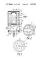
- FIG. 1 is a cross-sectional view of a fuel processor device adapted for replacing a fuel filter and further showing a fluid flow baffle in accordance with a first embodiment of this invention
- FIG. 2 is a bottom view of the fuel processor shown in FIG. 1 with certain components removed;
- FIG. 3 is a top view of the fuel processor shown in FIG. 1;
- FIG. 4 is a side elevational view of the fluid flow baffle shown in FIG. 1 removed from the associated fuel processor;
- FIG. 5 is a bottom view of the fuel processor shown in FIG. 4.
- FIG. 6 is a cross-sectional view of a fuel processor device incorporating a fluid flow baffle in accordance with a second embodiment of this invention.
- fluid flow baffle 10 is shown incorporated into fuel processor 12 in FIG. 1, and is shown separately in FIGS. 4 and 5.
- Fuel processor 12 like the remainder of those described within the parent application, is adapted for replacing an existing fuel filter device.
- Fuel processor 12 is particularly designed to replace a throwaway type fuel filter and, for the sake of illustration purposes only, is generally similar to the fuel processor depicted in FIG. 12 of the parent patent application.
- Fuel processor 12, shown herein, differs principally from that shown in FIG. 12 of the parent application in that it does not require a through bolt for attaching the processor to the filter mounting pad and employs alternate means for supporting the filter element.
- Fuel processor 12 includes canister 14 having an upper plate 16 which defines a plurality of angularly spaced fuel inlet ports 18, and a central threaded fuel outlet port 20.
- canister 14 is shown having a cylindrical shape, it could be formed in any number of desired shapes, e.g. conical, square, prism, pyramidal, etc.
- Upper plate 16 and fuel inlet and outlet ports 18 and 20 are positioned to mate with the associated surfaces and structures of a filter mounting block (not shown) which would include a central hollow threaded boss.
- Upper seal 22 provides a fluidtight seal between fuel processor 12 and the associated filter mounting block.
- Canister 14 preferably defines a radially inwardly deformed rib 24 and has internally threaded ring 26 attached to the perimeter of its lower opened end.
- Particulate filter element 28 is disposed within canister 14 and is a generally spool-shaped filter having a cylindrical outer surface 30 and a cylindrical inner surface 32, preferably defined by rigid perforated tube 34. Inner and outer surfaces 30 and 32 of filter 28 may, however, have any desired shape.
- the lower end of filter element 28 is enclosed by bottom plate 36, whereas the upper end has an opened center defined by top plate 38.
- Seal member 40 is provided which creates a fluidtight seal around the inside opening of top plate 38, so that fuel entering through fuel inlet ports 18 cannot flow directly to outlet port 20 thereby bypassing filter element 28.
- Particulate filter element 28 is held in position within canister 14 by formed wire retainer 54 which engages rib 24 and urges plug 56, and consequently filter element 28, into tight sealing engagement with seal member 40.
- Lower plate 42 is provided having external threads 44 which mesh with the internal threads of lower plate 42, and a fluid seal is provided by element 46. As discussed in the parent patent application, a number of various elements can be provided within a lower plate structure. As shown by FIG. 1 for illustration purposes only, lower plate 42 includes water sensor 48, drain valve 50, and electrical resistance heater 52.
- Fuel processor 12 operates generally as described by the parent patent application in that fuel enters through inlet ports 18 and flows downwardly into the lower chamber area 60 of canister 14 defined between particulate filter element 28 and lower plate 42. High density impurities and water are removed from the fuel as it passes into lower chamber area 60. If necessary, heater 52 is energized to elevate the temperature of the fuel within chamber area 60. Thereafter, fuel flows through particulate filter element 28 in a radially inward direction to the chamber defined within perforated tube 34 and exits processor 12 through fuel outlet port 20. Once particulate filter element 28 has become contaminated, it may be easily removed by detaching fuel processor 12 from the associated mounting structure and/or removing lower plate 42, enabling retainer 54 to be released and filter element 28 to be replaced.
- fluid flow baffle 10 is incorporated into fuel processor 12.
- Fluid flow baffle 10 is generally cup-shaped and has top 62 with a central port 64, and sides 66 preferably having a corrugated form.
- Baffle sides 66 are shaped to be positioned between filter 28 and canister 14.
- the corrugations of baffle 10 are formed along lines generally parallel to the longitudinal axis of the baffle.
- Baffle sides 66 may, however, have a number of other configurations such as a cylindrical or conical shape. Further, sides 66 could be corrugated in a different manner than that shown herein, for example, by providing different sizes and spacing of corrugations.
- Baffle 10 surrounds filter 28 and its lower edge 96 extends slightly below filter element lower plate 36 and defines an opened bottom end.
- baffle sides 66 preferably have a slight taper or draft angle. Corrugating sides 66 of baffle 10, in addition to other advantages, enable the baffle to have a diameter at its lower edge 96 before it is installed which is greater than the inside diameter of canister 14. During installation, baffle 10 becomes radially compressed to firmly retain it in canister 14 and further positions the baffle away from direct contact with filter element 28 which may have a fragile outer surface 30.
- Fluid flow baffle 10 is installed within fuel processor 12 as shown in FIG. 1 by trapping top 62 between filter element top plate 38 and seal member 40.
- fuel flowing into the fuel processor from fuel inlets 18 flows downwardly along channels defined by the corrugations on the radially outer side surface of baffle 10.
- the fuel then flows into chamber area 60 where heavy particulates, water, and other high density impurities become separated from the fuel and settle out. Thereafter, fuel flows upwardly along channels defined by the inside corrugated surface of baffle 10 and then through particulate filter element 28.
- Baffle 10 prevents incoming fuel from directly contacting filter element 28 prior to its flow into lower chamber area 60.
- Baffle 10 in addition to extending the useful life of filter element 28, also enhances the thermal efficiency of fuel processor 12 when it is operating in a fuel heating mode.
- baffle 10 in conjunction with heating element 52, direct contact between cold incoming fuel and filter media element 28 is prevented. Therefore, only warmed fuel directly contacts filter element 28, thereby aiding in the prevention of an accumulation of waxed fuel and ice from developing on the outer surface of the filter element which can cause fuel flow stoppage.
- baffle 10 improves the thermal efficiency of fuel processor 12 by separating the cold incoming fuel from warmed fuel. As shown in FIG.
- Baffle 10 and cold fuel flowing downwardly along the exterior surface of the baffle act as insulating layers which reduce heat loss by fuel warmed by heating element 52.
- Baffle 10 also provides a surface which is relatively "slippery" to accumulate solid masses of waxed fuel and ice such that these masses quickly separate from baffle 10 and fall to the lower portion of fuel processor 12 where they become heated and melted.
- FIG. 6 illustrates an alternate embodiment of a fuel processor 68 and baffle 70 according to this invention.
- Fuel processor 68 incorporates a modified filter mounting heat 72 which provides a flow direction of fuel opposite to that previously described, i.e. fuel enters fuel processor 68 through a central inlet port 74 and exits through one or more radially outwardly positioned outlet ports 76. This placement of ports 74 and 76 provides a direction of fuel flow through filter element 78 from its center in a radially outer direction.
- Fuel processor 68 includes lower plate 80 which threadingly engages canister 82 and includes heater element 84, water sensor 86, and drain valve 88. Any means of attaching canister 82 to filter mounting head 72 can be employed such as threaded fasteners, etc.
- fuel processor 68 depicted in FIG. 6 further includes fluid flow baffle 70 which performs a function similar to that of baffle 10 in that it separates incoming fuel from fuel which has flowed into lower chamber area 94. Due to the opposite direction of fuel flow provided by fuel processor 68 as compared with the previously described embodiment, fuel flow baffle 70 is positioned within the cylindrical inside surface 90 of filter element 78. Baffle 70 includes a radially outwardly extending flange 92 which becomes clamped or otherwise sealed between filter mounting head 72 and filter element 78.
- Fuel flowing into inlet port 74 is prevented from direct contact with the inside surface of filter element 78 until it flows into lower chamber area 94 where water and heavy particulate matter become separated therefrom and the fuel becomes heated (if needed) by heater element 84. Once exposed to lower chamber area 94, fuel is permitted to flow along the outer surface of baffle 70 and penetrates filter element 74.
Landscapes
- Chemical & Material Sciences (AREA)
- Engineering & Computer Science (AREA)
- Chemical Kinetics & Catalysis (AREA)
- Physics & Mathematics (AREA)
- Thermal Sciences (AREA)
- Combustion & Propulsion (AREA)
- Mechanical Engineering (AREA)
- General Engineering & Computer Science (AREA)
- Filtration Of Liquid (AREA)
- Cooling, Air Intake And Gas Exhaust, And Fuel Tank Arrangements In Propulsion Units (AREA)
- Feeding And Controlling Fuel (AREA)
- Supplying Secondary Fuel Or The Like To Fuel, Air Or Fuel-Air Mixtures (AREA)
Abstract
Description
Claims (19)
Priority Applications (4)
| Application Number | Priority Date | Filing Date | Title |
|---|---|---|---|
| US06/769,567 US4676895A (en) | 1984-06-25 | 1985-08-26 | Fluid flow baffle for fuel processor |
| EP86306459A EP0213889A3 (en) | 1985-08-26 | 1986-08-20 | Fluid flow baffle for fuel processor |
| JP61198791A JPS6273007A (en) | 1985-08-26 | 1986-08-25 | Fuel treater device and baffle thereof |
| ES8601324A ES2001884A6 (en) | 1985-08-26 | 1986-08-25 | Fluid flow baffle for fuel processor. |
Applications Claiming Priority (2)
| Application Number | Priority Date | Filing Date | Title |
|---|---|---|---|
| US06/624,413 US4680110A (en) | 1984-01-23 | 1984-06-25 | Filter block mounted fuel processor apparatus |
| US06/769,567 US4676895A (en) | 1984-06-25 | 1985-08-26 | Fluid flow baffle for fuel processor |
Related Parent Applications (1)
| Application Number | Title | Priority Date | Filing Date |
|---|---|---|---|
| US06/624,413 Continuation-In-Part US4680110A (en) | 1984-01-23 | 1984-06-25 | Filter block mounted fuel processor apparatus |
Publications (1)
| Publication Number | Publication Date |
|---|---|
| US4676895A true US4676895A (en) | 1987-06-30 |
Family
ID=25085836
Family Applications (1)
| Application Number | Title | Priority Date | Filing Date |
|---|---|---|---|
| US06/769,567 Expired - Lifetime US4676895A (en) | 1984-06-25 | 1985-08-26 | Fluid flow baffle for fuel processor |
Country Status (4)
| Country | Link |
|---|---|
| US (1) | US4676895A (en) |
| EP (1) | EP0213889A3 (en) |
| JP (1) | JPS6273007A (en) |
| ES (1) | ES2001884A6 (en) |
Cited By (17)
| Publication number | Priority date | Publication date | Assignee | Title |
|---|---|---|---|---|
| US4855041A (en) * | 1987-04-24 | 1989-08-08 | Parker Hannifin Corporation | Fluid filter drain assembly |
| US4898668A (en) * | 1988-09-30 | 1990-02-06 | Stanadyne Automotive Corp. | Fuel filter with heater |
| US4933093A (en) * | 1989-04-20 | 1990-06-12 | Keller Russel D | Fuel filter |
| US4944343A (en) * | 1987-08-29 | 1990-07-31 | Mueller Fritz | Apparatus for heating fuel |
| DE4131353A1 (en) * | 1991-03-28 | 1992-10-01 | Knecht Filterwerke Gmbh | Fluid filter with annular element - has only element interchangeable |
| US5249623A (en) * | 1987-08-29 | 1993-10-05 | Mueller Fritz | Rubber heat exchanger |
| US5378358A (en) * | 1993-05-10 | 1995-01-03 | Park; Robert | Fuel processing unit |
| US5589060A (en) * | 1991-03-28 | 1996-12-31 | Knecht Filterwerke Gmbh | Filter for liquids, in particular internal-combustion engine lubricant oils |
| US5667678A (en) * | 1995-04-13 | 1997-09-16 | Advanced Performance Technology, Inc. | Plastic fluid filter and method for assembling same |
| US5682661A (en) * | 1993-12-30 | 1997-11-04 | Hurner; Erwin E. | Fuel system with sight-glass |
| US5783078A (en) * | 1996-10-12 | 1998-07-21 | Dana Corporation | Fuel/water separator filter without flow diverters and method of making same |
| US5817234A (en) * | 1995-04-13 | 1998-10-06 | Advanced Performance Technology, Inc. | Fluid filter and method for assembling same |
| US20040188346A1 (en) * | 2003-03-28 | 2004-09-30 | Cline L. Steven | Filter apparatus and associated method |
| US20060006124A1 (en) * | 2004-07-12 | 2006-01-12 | Yates Brian G | Filter cartridge and method and apparatus for replacing same |
| US20060102548A1 (en) * | 2004-11-15 | 2006-05-18 | Nishaj Attassery | Fluid filter assembly with notched case |
| US20070208662A1 (en) * | 2006-02-10 | 2007-09-06 | The Western Union Company | Biometric based authorization systems for electronic fund transfers |
| US20080149550A1 (en) * | 2006-12-20 | 2008-06-26 | Carlos Del Pino Suarez | Filter fuel assembly |
Families Citing this family (10)
| Publication number | Priority date | Publication date | Assignee | Title |
|---|---|---|---|---|
| US4740299A (en) * | 1985-05-14 | 1988-04-26 | Parker Hannifin Corporation | Filter assembly with threaded collection bowl |
| US4997555A (en) * | 1985-05-14 | 1991-03-05 | Parker Hannifin Corporation | Fuel filter assembly with heater |
| CA1312018C (en) * | 1987-03-30 | 1992-12-29 | John F. Church | Fuel filter assembly with heater |
| IT1233224B (en) * | 1989-07-21 | 1992-03-20 | Gilardini Spa | PRE DECANTER FILTER FOR DIESEL ENGINE FUEL |
| DE4134367A1 (en) * | 1991-10-17 | 1993-04-22 | Bosch Gmbh Robert | LIQUID FILTER |
| JPH06135677A (en) * | 1992-01-16 | 1994-05-17 | Hitoshi Mori | Horizontal suspending-up device for pca plate |
| US5547565A (en) * | 1994-12-05 | 1996-08-20 | Baldwin Filters, Inc. | Fuel/water separator with adaptor plate for drain valve and water detector |
| DE29602330U1 (en) * | 1996-02-10 | 1996-05-30 | Ing. Walter Hengst GmbH & Co KG, 48147 Münster | Filter drain with spring lock |
| EP0946249A4 (en) * | 1996-10-02 | 2000-10-11 | David Paul Goodrich | Filter assembly |
| GB0216115D0 (en) | 2002-07-11 | 2002-08-21 | Parker Hannifin U K Ltd | Self-venting solenoid drain valves |
Citations (8)
| Publication number | Priority date | Publication date | Assignee | Title |
|---|---|---|---|---|
| US2294107A (en) * | 1941-02-18 | 1942-08-25 | Albert J Beck | Gas filter |
| US3568835A (en) * | 1968-07-01 | 1971-03-09 | Int Marketing Corp The | Liquid separator and filter unit |
| US3762467A (en) * | 1970-10-26 | 1973-10-02 | Dewandre Co Ltd C | Heat exchangers |
| US3883428A (en) * | 1973-09-14 | 1975-05-13 | Robert W Waring | Filter |
| US4091265A (en) * | 1975-08-06 | 1978-05-23 | Racor Industries, Inc. | Fuel filter heating assembly |
| US4298465A (en) * | 1979-06-07 | 1981-11-03 | Racor Industries, Inc. | Fuel filter and water separator apparatus |
| US4389310A (en) * | 1977-12-26 | 1983-06-21 | Hitachi, Ltd. | Cold trap |
| US4476028A (en) * | 1983-04-25 | 1984-10-09 | Stant Inc. | Heater and water probe |
Family Cites Families (2)
| Publication number | Priority date | Publication date | Assignee | Title |
|---|---|---|---|---|
| US4470301A (en) * | 1982-09-22 | 1984-09-11 | Fram Corporation | Probe and drain assembly for fuel oil/water separator |
| US4680110A (en) * | 1984-01-23 | 1987-07-14 | Davco Manufacturing Corporation | Filter block mounted fuel processor apparatus |
-
1985
- 1985-08-26 US US06/769,567 patent/US4676895A/en not_active Expired - Lifetime
-
1986
- 1986-08-20 EP EP86306459A patent/EP0213889A3/en not_active Withdrawn
- 1986-08-25 JP JP61198791A patent/JPS6273007A/en active Pending
- 1986-08-25 ES ES8601324A patent/ES2001884A6/en not_active Expired
Patent Citations (8)
| Publication number | Priority date | Publication date | Assignee | Title |
|---|---|---|---|---|
| US2294107A (en) * | 1941-02-18 | 1942-08-25 | Albert J Beck | Gas filter |
| US3568835A (en) * | 1968-07-01 | 1971-03-09 | Int Marketing Corp The | Liquid separator and filter unit |
| US3762467A (en) * | 1970-10-26 | 1973-10-02 | Dewandre Co Ltd C | Heat exchangers |
| US3883428A (en) * | 1973-09-14 | 1975-05-13 | Robert W Waring | Filter |
| US4091265A (en) * | 1975-08-06 | 1978-05-23 | Racor Industries, Inc. | Fuel filter heating assembly |
| US4389310A (en) * | 1977-12-26 | 1983-06-21 | Hitachi, Ltd. | Cold trap |
| US4298465A (en) * | 1979-06-07 | 1981-11-03 | Racor Industries, Inc. | Fuel filter and water separator apparatus |
| US4476028A (en) * | 1983-04-25 | 1984-10-09 | Stant Inc. | Heater and water probe |
Cited By (22)
| Publication number | Priority date | Publication date | Assignee | Title |
|---|---|---|---|---|
| US4855041A (en) * | 1987-04-24 | 1989-08-08 | Parker Hannifin Corporation | Fluid filter drain assembly |
| US4944343A (en) * | 1987-08-29 | 1990-07-31 | Mueller Fritz | Apparatus for heating fuel |
| US5249623A (en) * | 1987-08-29 | 1993-10-05 | Mueller Fritz | Rubber heat exchanger |
| US4898668A (en) * | 1988-09-30 | 1990-02-06 | Stanadyne Automotive Corp. | Fuel filter with heater |
| US4933093A (en) * | 1989-04-20 | 1990-06-12 | Keller Russel D | Fuel filter |
| DE4131353A1 (en) * | 1991-03-28 | 1992-10-01 | Knecht Filterwerke Gmbh | Fluid filter with annular element - has only element interchangeable |
| US5589060A (en) * | 1991-03-28 | 1996-12-31 | Knecht Filterwerke Gmbh | Filter for liquids, in particular internal-combustion engine lubricant oils |
| US5378358A (en) * | 1993-05-10 | 1995-01-03 | Park; Robert | Fuel processing unit |
| US5776332A (en) * | 1993-12-30 | 1998-07-07 | Hurner; Erwin E. | Fuel system with sight-glass |
| US5682661A (en) * | 1993-12-30 | 1997-11-04 | Hurner; Erwin E. | Fuel system with sight-glass |
| US5837132A (en) * | 1993-12-30 | 1998-11-17 | Hurner; Erwin E. | Fuel system with sight-glass |
| US5667678A (en) * | 1995-04-13 | 1997-09-16 | Advanced Performance Technology, Inc. | Plastic fluid filter and method for assembling same |
| US5817234A (en) * | 1995-04-13 | 1998-10-06 | Advanced Performance Technology, Inc. | Fluid filter and method for assembling same |
| US5783078A (en) * | 1996-10-12 | 1998-07-21 | Dana Corporation | Fuel/water separator filter without flow diverters and method of making same |
| US6896803B2 (en) | 2003-03-28 | 2005-05-24 | Arvin Technologies, Inc. | Filter apparatus and associated method |
| US20040188346A1 (en) * | 2003-03-28 | 2004-09-30 | Cline L. Steven | Filter apparatus and associated method |
| US20060006124A1 (en) * | 2004-07-12 | 2006-01-12 | Yates Brian G | Filter cartridge and method and apparatus for replacing same |
| US20060102548A1 (en) * | 2004-11-15 | 2006-05-18 | Nishaj Attassery | Fluid filter assembly with notched case |
| US7708147B2 (en) | 2004-11-15 | 2010-05-04 | Purolator Filters Na Llc | Fluid filter assembly with notched case |
| US20070208662A1 (en) * | 2006-02-10 | 2007-09-06 | The Western Union Company | Biometric based authorization systems for electronic fund transfers |
| US20080149550A1 (en) * | 2006-12-20 | 2008-06-26 | Carlos Del Pino Suarez | Filter fuel assembly |
| US7857971B2 (en) | 2006-12-20 | 2010-12-28 | Del Pino Suarez Carlos | Filter fuel assembly |
Also Published As
| Publication number | Publication date |
|---|---|
| JPS6273007A (en) | 1987-04-03 |
| EP0213889A2 (en) | 1987-03-11 |
| ES2001884A6 (en) | 1988-07-01 |
| EP0213889A3 (en) | 1988-12-14 |
Similar Documents
| Publication | Publication Date | Title |
|---|---|---|
| US4676895A (en) | Fluid flow baffle for fuel processor | |
| EP0168160B1 (en) | Filter block mounted fuel processor apparatus | |
| US5017285A (en) | Fuel filter and cartridge assembly | |
| EP0593434B1 (en) | Fuel filter | |
| US4470301A (en) | Probe and drain assembly for fuel oil/water separator | |
| US4477345A (en) | Filter separator with heater | |
| EP0106736A2 (en) | Separating device and cartridge therefor | |
| US4372847A (en) | Fuel filter assembly and cartridge | |
| US3931011A (en) | Fluid separation apparatus | |
| US4976852A (en) | Fuel filter | |
| US4298465A (en) | Fuel filter and water separator apparatus | |
| US4579653A (en) | Side-by-side fuel processor apparatus | |
| GB2078536A (en) | Fuel filter assembly and cartridge | |
| CA1160917A (en) | Fuel processor apparatus for diesel engine powered vehicles | |
| US4732671A (en) | Diesel fuel filter/water separator | |
| US5240593A (en) | Apparatus for the purification of fluids | |
| GB2106002A (en) | Fuel processor apparatus | |
| US5174892A (en) | Permanent fuel filter | |
| US20040140271A1 (en) | Method of and system for fluid purification | |
| US3065854A (en) | Centrifuging and liquid-purifying device | |
| US20020117441A1 (en) | Fuel processing and filtering apparatus | |
| RU2806743C2 (en) | Filter assembly with bypass cap | |
| US1680716A (en) | Oil purifier |
Legal Events
| Date | Code | Title | Description |
|---|---|---|---|
| AS | Assignment |
Owner name: DAVCO MANUFACTURING CORPORATION 4601 PLATT ROAD AN Free format text: ASSIGNMENT OF ASSIGNORS INTEREST.;ASSIGNOR:DAVIS, LELAND L.;REEL/FRAME:004449/0676 Effective date: 19850816 |
|
| STCF | Information on status: patent grant |
Free format text: PATENTED CASE |
|
| CC | Certificate of correction | ||
| FEPP | Fee payment procedure |
Free format text: PAYOR NUMBER ASSIGNED (ORIGINAL EVENT CODE: ASPN); ENTITY STATUS OF PATENT OWNER: LARGE ENTITY |
|
| FPAY | Fee payment |
Year of fee payment: 4 |
|
| FPAY | Fee payment |
Year of fee payment: 8 |
|
| AS | Assignment |
Owner name: DAVCO MANUFACTURING ACQUISITION, L.L.C., MICHIGAN Free format text: ASSIGNMENT OF ASSIGNORS INTEREST;ASSIGNOR:DAVCO MANUFACTURING CORPORATION;REEL/FRAME:007470/0070 Effective date: 19950314 |
|
| AS | Assignment |
Owner name: DAVCO MANUFACTURING, L.L.C., MICHIGAN Free format text: CHANGE OF NAME;ASSIGNOR:DAVCO MANUFACTURING ACQUISITION, L.L.C.;REEL/FRAME:008604/0074 Effective date: 19961220 |
|
| FEPP | Fee payment procedure |
Free format text: PAT HLDR NO LONGER CLAIMS SMALL ENT STAT AS SMALL BUSINESS (ORIGINAL EVENT CODE: LSM2); ENTITY STATUS OF PATENT OWNER: LARGE ENTITY |
|
| AS | Assignment |
Owner name: GENERAL ELECTRICAL CAPITAL CORPORATION, CONNECTICU Free format text: SECURITY AGREEMENT;ASSIGNOR:DAVCO MANUFACTURING, LLC;REEL/FRAME:009245/0110 Effective date: 19980213 |
|
| FPAY | Fee payment |
Year of fee payment: 12 |
|
| AS | Assignment |
Owner name: BANK ONE, MICHIGAN, MICHIGAN Free format text: ASSIGNMENT OF SECURITY AGREEMENT;ASSIGNOR:GENERAL ELECTRIC CAPITAL CORPORATION;REEL/FRAME:010977/0211 Effective date: 20000606 |
|
| AS | Assignment |
Owner name: DAVCO TECHNOLOGY, LLC, MICHIGAN Free format text: ASSIGNMENT OF ASSIGNORS INTEREST;ASSIGNOR:DAVCO MANUFACTURING L.L.C.;REEL/FRAME:011923/0090 Effective date: 20010508 |
|
| AS | Assignment |
Owner name: DAVCO MANUFACTURING, L.L.C., NEW YORK Free format text: TERMINATION OF ASSIGNMENT FOR SECURITY;ASSIGNOR:BANK ONE NA;REEL/FRAME:015418/0283 Effective date: 20041028 |