EP4018043B1 - Method and system for treating a road surface using an industrial vehicle - Google Patents
Method and system for treating a road surface using an industrial vehicle Download PDFInfo
- Publication number
- EP4018043B1 EP4018043B1 EP20775064.7A EP20775064A EP4018043B1 EP 4018043 B1 EP4018043 B1 EP 4018043B1 EP 20775064 A EP20775064 A EP 20775064A EP 4018043 B1 EP4018043 B1 EP 4018043B1
- Authority
- EP
- European Patent Office
- Prior art keywords
- road surface
- subarea
- industrial vehicle
- treatment parameters
- vehicle
- Prior art date
- Legal status (The legal status is an assumption and is not a legal conclusion. Google has not performed a legal analysis and makes no representation as to the accuracy of the status listed.)
- Active
Links
Images


Classifications
-
- E—FIXED CONSTRUCTIONS
- E01—CONSTRUCTION OF ROADS, RAILWAYS, OR BRIDGES
- E01H—STREET CLEANING; CLEANING OF PERMANENT WAYS; CLEANING BEACHES; DISPERSING OR PREVENTING FOG IN GENERAL CLEANING STREET OR RAILWAY FURNITURE OR TUNNEL WALLS
- E01H10/00—Improving gripping of ice-bound or other slippery traffic surfaces, e.g. using gritting or thawing materials ; Roadside storage of gritting or solid thawing materials; Permanently installed devices for applying gritting or thawing materials; Mobile apparatus specially adapted for treating wintry roads by applying liquid, semi-liquid or granular materials
- E01H10/007—Mobile apparatus specially adapted for preparing or applying liquid or semi-liquid thawing material or spreading granular material on wintry roads
-
- E—FIXED CONSTRUCTIONS
- E01—CONSTRUCTION OF ROADS, RAILWAYS, OR BRIDGES
- E01H—STREET CLEANING; CLEANING OF PERMANENT WAYS; CLEANING BEACHES; DISPERSING OR PREVENTING FOG IN GENERAL CLEANING STREET OR RAILWAY FURNITURE OR TUNNEL WALLS
- E01H5/00—Removing snow or ice from roads or like surfaces; Grading or roughening snow or ice
- E01H5/04—Apparatus propelled by animal or engine power; Apparatus propelled by hand with driven dislodging or conveying levelling elements, conveying pneumatically for the dislodged material
- E01H5/06—Apparatus propelled by animal or engine power; Apparatus propelled by hand with driven dislodging or conveying levelling elements, conveying pneumatically for the dislodged material dislodging essentially by non-driven elements, e.g. scraper blades, snow-plough blades, scoop blades
Definitions
- This invention relates to a method and to a system for treating a road surface using an industrial vehicle.
- known vehicles of the type mentioned above the operation of which is managed by electronic control devices adapted to control product spreading parameters (e.g. the quantity of product spread per square metre, the width and symmetry of spreading, etc.) in a predetermined manner.
- product spreading parameters e.g. the quantity of product spread per square metre, the width and symmetry of spreading, etc.
- known electronic control devices comprise a memory containing spreading parameters selected for the specific morphological and/or environmental and/or meteorological conditions of the route where the vehicle is supposed to operate.
- User interface means are provided inside the vehicle, for selecting the most suitable program for the route taken by the vehicle itself, so as to determine the quantity of product to deliver and the delivery methods.
- changes in the morphological/environmental conditions of the route may occur while the vehicle is moving from a central area of a city where it is operating (typically warmer and with low humidity values) to a peripheral area, e.g. A river area (typically colder and more humid). If the vehicle is operating in cold conditions (e.g. after a snowfall), it is highly likely that the central area of the city will have wet or partially melted snow, while the river area will have icy portions along the route.
- Patent document US2014/136023 relates generally to vehicle mounted spreading systems and more particularly to a system for controlling vehicle mounted spreaders.
- Patent document EP0853708 relates to methods, apparatus and control systems for dispensing salt, grit or other substances on surfaces, for example for spreading salt or grit over icy roads.
- Patent document WO97/13926 relates to methods, apparatus and control systems for dispensing salt, grit or other substances on surfaces, for example for spreading salt or grit over icy roads.
- Patent document EP3412833 relates to the field of intelligent control, and in particular to an automatic moving snow removal device.
- Patent document EP3067469 relates to an antifreezing agent automatic spray control apparatus, an antifreezing agent automatic spray control program, and an antifreezing agent automatic spray control method for automatically spraying an antifreezing agent according to the surface condition of the road.
- the purpose of this invention is to provide a method and a system for treating a road surface using an industrial vehicle, which makes it possible to overcome, at least partially, the drawbacks of the prior art.
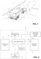
- Figure 1 shows a vehicle, indicated as a whole with the number 1, in particular an industrial vehicle, equipped with a tractor 2, a tank 3 for housing one or more products 7 (solid or liquid) for treating a road surface 9, and delivery means 5, fitted, for example, to the rear of the tractor 2, and adapted to spread the product 7 on the road surface 9 of a road route P along which the vehicle 1 is moving.
- the vehicle 1 is adapted to deliver antifreeze products (e.g., melting or abrasive chlorides, both liquid and solid).
- antifreeze products e.g., melting or abrasive chlorides, both liquid and solid.
- the delivery means 5 can be controlled automatically to perform one or more of the following operations:
- the spreading mode can be defined by one or more spreading parameters, including:
- the vehicle 1 also comprises a snow plough blade 4 equipped with a support arm and attachment of the blade 4 to the tractor 2 and a blade handling unit 6, which is itself known and partially illustrated.
- the blade 4 comprises, in a known way, a rolling body 4a, a removal knife, or scraper knife, 4b permanently attached to a lower portion of the rolling body 4a and protruding downwards to remove at least some of the snow on the road surface 9.
- the knife 4b is made of metal or polymer material.
- the handling unit 6 can be controlled automatically to perform one or more of the following operations:
- the handling unit 6 and the delivery means 5 can be controlled automatically to perform the above-mentioned operations, as a function of the operating parameters, including (but not limited to) one or more of the following:
- vehicle 1 may spread other products on the road surface, such as granular abrasive products (such as gravel or sand) or liquid-type antifreeze products (such as salt solutions or melting solutions in general) designed to hinder (or reduce) the formation of ice and/or the deposit of snow on the road surface.
- granular abrasive products such as gravel or sand
- liquid-type antifreeze products such as salt solutions or melting solutions in general
- the vehicle 1 is also equipped with an electronic control device or system 10 adapted to control the delivery means 5 to adjust, in a known way, the quantity of product delivered and the delivery modes as a function of a number of spreading parameters.
- the electronic control device 10 is also adapted to control the snow plough blade 4, activating the handling unit 6 of the blade 4.
- the electronic control device 10 comprises: a GPS receiver 15 for the purpose of generating an output signal S related to the position and forward direction of the vehicle 1; a processing unit 17 cooperating with the GPS receiver 15; and a memory 19 communicating with the processing unit 17.
- the handling unit 6 is controllable by the processing unit 17 as a function of one or more of the above-mentioned operating parameters.
- the vehicle 1 also comprises a transceiver unit 18, either integrated into the device 10 or external to it, and operationally coupled to it.
- the transceiver unit 18 is configured to receive data signals using a known protocol.
- the transceiver unit 18 is configured to receive data over a wireless channel (e.g. Wi-Fi or cellular network, including 3G, 4G and/or 5G), or via a cable, using a public or private network, as required.
- a wireless channel e.g. Wi-Fi or cellular network, including 3G, 4G and/or 5G
- the transceiver unit 18 communicates with the processing unit 17 to transfer the data received to it so that the data can be processed and interpreted.
- the device 10 optionally comprises an interface unit 21 communicating with the processing unit 17 and adapted to be used by an operator (not shown) in the passenger compartment of the vehicle 1 for monitoring and controlling salt-spreading/snow-removal operations and/or to detect any abnormalities or alarms.
- the interface unit 21 can also be integrated with the processing unit 17.
- the processing unit 17 is adapted to send control signals D to an interface 5a of the delivery means 5 to control the quantity of salt delivered and the spreading methods. For example, by means of the control signals D, the quantity of salt delivered per square meter, the width of spreading, the symmetry of spreading (lateral, central), the percentage humidification of the salt that is spread, etc. can be adjusted (in a known way).
- the processing unit 17 is also adapted to send control signals L towards the handling unit 6 of the blade 4 to control, in a known way, blade 4 operating parameters (pressure on the ground, approach angle, etc.).
- the GPS receiver 15 cooperates with a GPS satellite tracking system to detect the absolute position of the vehicle 1 on the earth's surface.
- the invention uses the GPS satellite tracking system to determine the position and direction of the vehicle 1 and control the delivery means 5 and the handling unit 6 accordingly, based on the geographical position detected (as detailed below).
- the set of spreading parameters and operating parameters of the blade relating to a route that can be taken by the vehicle 1, define the salt-spreading/snow-removal methods suitable for specific morphological conditions of the route and/or particular weather and/or environmental conditions of the road surface (presence and type of snow, ice, water, hail, etc.).
- the data representing these spreading/snow-removal methods are contained in the memory 19, which communicates with the processing unit 17 to generate the control signal D of the delivery means 5.
- the different salt-spreading methods are automatically selected according to the position of the vehicle along the road route detected by the GPS receiver.
- the different methods for adjusting the handling unit 6 of the blade 4 are also automatically selected based on the position of the vehicle along the road route detected by the GPS receiver.
- Figure 3 shows a method of acquiring environmental data and/or information for an area where the vehicle 1 is supposed to operate.
- Figure 4 illustrates a method implemented on board the vehicle 1 for operating the systems for spreading salt and handling the blade 4.
- a digital map 20 of a geographical area is provided in which the vehicle 1 is supposed to perform the cleaning/securing of the roads (e.g. spreading of antifreeze and/or abrasive products, removal of snow and/or ice, etc.).
- Figure 5 is an illustrative graphic representation of the digital map 20.
- This digital map 20 includes, for example, the detailed planimetric representation of a city, province, region, etc., or part thereof.
- the digital map 20 is divided into a plurality of subareas 20a-20e covering the territorial extension of the city, or part thereof, in which the vehicle 1 is supposed to operate.
- Each subarea 20a-20e is bounded by sides of a polygon, or other geometric shape, and is chosen in such a way that the portion of territory enclosed within it has uniform features. These features include, but are not limited to: morphological, environmental, estimated or predicted temperature, climatic, and estimated or predicted traffic features.
- one or more of the above-mentioned features are shared (or estimated to be so, or believed so by an operator) for each point inside the corresponding subarea 20a-20e (or for a majority of points inside the corresponding subarea 20a-20e), and, consequently, differ between one subarea 20a-20e and another subarea 20a-20e.
- the significant features taken into account for the subarea division include: altitude, estimated temperatures, environmental humidity, wind direction, estimated traffic, presence of activities that may induce local heating, type of road paving, presence of side barriers, or cut routes, etc.
- subareas 20a-20e are, in itself, a known procedure in the state of the art and may be performed by an operator in a known way and, thus, is described no further.
- one or more patrolling vehicles 40 are sent along routes that cross, even only partially, all the subareas 20a-20e, to acquire information relating to the environmental conditions of the road surface (presence and type of snow, ice, hail, water, etc.) and/or temperature and/or weather conditions (or other information still) in each corresponding subarea 20a-20e.
- the patrolling vehicles may also be vehicles that habitually run along tracts of the subareas 20a-20e, such as buses or taxis.
- the routes may be random or pre-set.
- the division into subareas 20a-20e is performed by taking into consideration features that are shared by each point (or a majority of points) belonging to the same subarea 20a-20e, it is enough that the patrolling vehicles 40 run along even only a portion of the corresponding subarea 20a-20e, each portion having a size or spatial extension (e.g. area) that is less than the total size or spatial extension (e.g. area) of the corresponding subarea 20a-20e.
- the portion of the corresponding subarea 20a-20e traversed by the patrolling vehicles 40 preferably has a minimum length chosen so that the environmental information acquired has a general and not a point value.
- the portion of the corresponding subarea 20a-20e traversed by the patrolling vehicles 40 is chosen from a length ranging from 0.5 km to 1 km. Lengths or distances greater than 1km are, however, possible.
- the information acquired is, therefore, associated with the whole subarea 20a-20e.
- the patrolling vehicles 40 may be private vehicles equipped for the purpose, or public vehicles (e.g. buses, trams, etc.) conveniently chosen based on the route programmed.
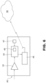
- each patrolling vehicle 40 is equipped with a sensor device (transducer) 42 for measuring the physical or chemical features, or physiochemical properties, of the road surface, and is adapted to provide knowledge on the state of the road, including the formation of ice or the accumulation of snow/hail/water.
- the sensor device 42 enables, therefore, the acquisition of information relating to the state of the road surface, distinguishing between dry, humid, wet, ice, snow, salt-residue.
- the device 42 also provides, optionally, a "grip" value for the tyres on the road surface, as a function of the quantity of water, snow, and ice detected.
- the sensor device 42 is configured to acquire additional types of information such as, for example, the environmental and/or road surface temperature, the environmental humidity, and/or the presence of obstacles or works that are underway.
- a sensor device adapted for this purpose is well known, for example, from US 2017/0131723 .
- sensors that are commercially available and can be used in the context of this invention, which is not, thus, limited to the choice of a specific one of these.
- a respective sensor device 42 is, thus, mounted on each patrolling vehicle 40, in a position so as to enable the acquisition of the above-mentioned information. If the sensor device 42 used does not enable the acquisition of all the above-mentioned information, it is possible to mount several sensors on the patrolling vehicles 40, each of which is equipped to acquire one piece, or a plurality of pieces, of information.
- the above-mentioned environmental information may also derive from transducers or sensors of various types already present on the road section.
- step 104 the information thus acquired (transduced) are sent to a processing unit 44, provided with, or coupled to, a memory 46, for storing such information.
- the vehicle 40 is provided with a geolocation system 47, via which the geographical position of the patrolling vehicles 40 is monitored.
- a geolocation system 47 via which the geographical position of the patrolling vehicles 40 is monitored.
- the patrolling vehicle 40 is also provided with a transmission unit 48 configured to acquire information from the memory 46 and to send it to a remote server 50 (e.g. a cloud-based platform).
- the information may be sent in real time, or at pre-set times (e.g. periodically) or at the end of the route, when the corresponding patrolling vehicle 40 re-enters the base, or according to additional timing methods.
- This information can be sent by using a wireless connection, freely chosen as required.
- a Wi-Fi network can be used, a cellular network (e.g. 3G, 4G, 5G, or another technology), a satellite transceiver network, etc.
- a cabled connection can also be used, or portable storage devices such as "hard-disks", “pen drives”, SD cards, etc.
- the transmission unit 48 also sends GPS data relating to the position of the patrolling vehicle 40 during use.
- the processing unit 44 associates the spatial position (GPS data) of the patrolling vehicle 40 and the data/information acquired via the sensor device 42, so that at each acquisition time the data and information transduced are uniquely associated, via the sensor device 42, with GPS coordinates of the patrolling vehicle 40 in the environment (subarea) under analysis. It is, thus, possible to identify the actual position of the patrolling vehicle 40 in the digital map 20 and, in particular, in relation to each subarea 20a-20e, and to know the road conditions in this position.
- GPS data GPS data
- the processing unit 44 associates the spatial position (GPS data) of the patrolling vehicle 40 and the data/information acquired via the sensor device 42, so that at each acquisition time the data and information transduced are uniquely associated, via the sensor device 42, with GPS coordinates of the patrolling vehicle 40 in the environment (subarea) under analysis. It is, thus, possible to identify the actual position of the patrolling vehicle 40 in the digital map 20 and, in particular, in relation to each subarea 20a-20e, and to know the road conditions in this position.
- the data and the information transmitted to the remote server 50 are associated with spreading parameters and/or control parameters of the blade 4 adapted to the environmental conditions detected (parameterisation step). This association is performed at the level of the remote server 50.
- the remote server 50 is provided with a data base by means of which it is possible to associate each piece of environmental information with a corresponding spreading parameter and/or operating method for the blade 4.
- the digital map 20 is stored at the level of the remote server 50 and the identification of the actual position of the patrolling vehicle 40 in the digital map 20 and, in particular, in relation to each subarea 20a-20e, is also performed at the level of the remote server 50.
- Other embodiments are possible, as is clear to a person skilled in the art.
- the database may be designed so as to associate, for corresponding environmental conditions detected by the sensor device 42, specific treatment parameters of the road surface including, but not only, the spreading of salt.
- specific treatment parameters of the road surface including, but not only, the spreading of salt.
- each macro-condition including:
- the thickness of the layer of snow (and/or snow mixed with water), or ice, or water, measured in millimetres on the road surface, is also taken into account.
- treatment values are automatically set, e.g. dosage of salt to be spread, measured in grams per square metre.
- Known sensor devices 42 that can be used in the context of this invention also provide a "grip" value for the tyres on the road surface, in the various conditions detected on the road surface, including: dry, with snow, with snow mixed with water, with water only, or with ice.
- the grip information is not provided directly by the sensor device 42 used, this information can, however, be inferred from the quantity of water, snow, or ice present on the road surface. As the quantity increases, the grip reduces (i.e. the grip value is inversely proportional to the thickness of water, snow, or ice detected).
- the treatment parameters for the road surface are changed. For example, if the grip is below the threshold, the quantity of salt spread is increased. This increase can be a fixed quantity or proportional or dependent on the shift of the actual grip in relation to the threshold. For example, the spreading of salt is increased by a percentage value (e.g. by 10%) for each corresponding reduction in percentage (e.g. by 10%) of the grip value detected.
- the quantity of salt spread is reduced. This decrease can be a fixed quantity or proportional or dependent on the shift of the actual grip in relation to the threshold. For example, the spreading of salt is reduced by a percentage value (e.g. by 10%) for each corresponding reduction in percentage (e.g. by 10%) of the grip value detected.
- subareas 20a-20e are chosen in such a way that they group together zones or points that are uniform from a morphological/environmental point of view, as previously discussed, it may happen that the patrolling vehicle 40 detects, in the same subarea 20a-20e environmental and/or grip conditions that are not uniform.
- the treatment parameters for treating these majority environmental and/or grip conditions are set for the whole subarea 20a-20e.
- the treatment parameters of the whole subarea 20a-20e are chosen at an intermediate value from the values expected for the different environmental conditions detected, or at a value included between the values expected for the different environmental conditions detected. For example, the choice of this value for the treatment parameters can be made using a weighted average. In this way, it is possible to provide adequate treatment for the few points with irregular environmental conditions and a non-oversized treatment for the other points with uniform environmental conditions.
- the updated treatment parameters of the road surface are, thus, transmitted from the remote server 50 to the vehicle 1, which implements them for treating the corresponding subarea 20a-20e.
- the updated treatment parameters of the road surface are transmitted from the remote server 50 to the vehicle 1 first and/or during the treatment of the road surface, in particular as a function of the route that the vehicle 1 will have to take or is taking.
- Figure 6 is only illustrative of a possible embodiment and is non-limiting of this invention; in fact, the memory 46 can be omitted if the data and information acquired, such as the GPS position, are sent in real time to the remote server 50.
- the sensor device 42, the processing unit 44, the GPS sensor device and/or the transmission unit 48 may be either integrated inside the same container or distributed on board the vehicle 40, and conveniently connected to each other.
- the environmental and road data and information are "real” or “actual” data, i.e. data acquired on the reference territory and not estimated using weather forecasts.
- step 200 the vehicle 1 acquires from the remote server 50 the environmental and road data and information stored and parameterised in it (to step 106 of Figure 3 ), together with the position indications (GPS coordinates) to which such environmental information refers.
- the position indications GPS coordinates
- the vehicle 1 sends the GPS data relating to its position (acquired via the GPS receiver 15) to the remote server 50 (via the processing unit 17 and the transceiver unit 18), and the remote server 50 sends commands relating to the spreading and handling parameters of the blade 4, associated with that specific geographical position, to the vehicle 1.
- step 202 the vehicle 1, after having received these commands via the transceiver unit 18, implements the delivery means 5, in accordance with the commands received (automatically and without the manual intervention of the operator), via the processing unit 17.
- step 204 the processing unit 17 continuously monitors, or at regular intervals, the position signal S provided by the GPS receiver, and checks if the route on which these parameter acquisition operations are being carried out is still included in the subarea 20a-20e, for which the current commands have been received, or whether there has been a change in subarea 20a-20e. This operation can be performed on board the vehicle 1 if the memory 19 stores the digital map 20. Conversely, the vehicle 1 continuously sends, or at time intervals, its GPS position to the remote server 50, which performs this check. If the subarea 20a-20e changes, the processing unit 17 acquires from the remote server 50 the new spreading parameters for the subarea 20a-20e that the vehicle 1 has entered, and implements the delivery means 5 in accordance with these new parameters (step 206).
- the vehicle 1 maintains the same spreading parameters and only changes them when it enters a different subarea 20a-20e.
- the memory 19 stores the latency values relating to the various mechanical implementations, so that the processing unit 17 is able to estimate, based on the position, direction, and speed values of the vehicle 1, when to implement the mechanical parts of the same with new spreading parameters.
- this invention applies in a self-evident manner to vehicles 1 configured to perform even one of the following operations: spreading and mechanical snow/ice removal using the blade 4.
- the operations performed remotely, by the server 50, and at a local level by the industrial vehicle 1 can be performed totally at the level of the industrial vehicle 1, if provided with processing and storage means that are powerful enough.
- the information acquired by the patrolling vehicles 40 during use are directly transferred to the industrial vehicle 1.
- this invention is applied, therefore, in a self-evident manner, to a situation in which the processing means of the remote server 50 and of the industrial vehicle 1 are either of the distributed or centralised type.
Landscapes
- Engineering & Computer Science (AREA)
- Architecture (AREA)
- Civil Engineering (AREA)
- Structural Engineering (AREA)
- Traffic Control Systems (AREA)
- Road Repair (AREA)
- Cleaning Of Streets, Tracks, Or Beaches (AREA)
Priority Applications (1)
| Application Number | Priority Date | Filing Date | Title |
|---|---|---|---|
| HRP20240651TT HRP20240651T1 (hr) | 2019-08-20 | 2020-08-20 | Metoda i sustav za obradu cestovne površine industrijskim vozilom |
Applications Claiming Priority (2)
| Application Number | Priority Date | Filing Date | Title |
|---|---|---|---|
| IT102019000014871A IT201900014871A1 (it) | 2019-08-20 | 2019-08-20 | Metodo e sistema per il trattamento di un manto stradale mediante un veicolo industriale |
| PCT/IB2020/057826 WO2021033157A1 (en) | 2019-08-20 | 2020-08-20 | Method and system for treating a road surface using an industrial vehicle |
Publications (2)
| Publication Number | Publication Date |
|---|---|
| EP4018043A1 EP4018043A1 (en) | 2022-06-29 |
| EP4018043B1 true EP4018043B1 (en) | 2024-05-08 |
Family
ID=69106057
Family Applications (1)
| Application Number | Title | Priority Date | Filing Date |
|---|---|---|---|
| EP20775064.7A Active EP4018043B1 (en) | 2019-08-20 | 2020-08-20 | Method and system for treating a road surface using an industrial vehicle |
Country Status (8)
| Country | Link |
|---|---|
| EP (1) | EP4018043B1 (pl) |
| DK (1) | DK4018043T3 (pl) |
| ES (1) | ES2982076T3 (pl) |
| FI (1) | FI4018043T3 (pl) |
| HR (1) | HRP20240651T1 (pl) |
| IT (1) | IT201900014871A1 (pl) |
| PL (1) | PL4018043T3 (pl) |
| WO (1) | WO2021033157A1 (pl) |
Families Citing this family (2)
| Publication number | Priority date | Publication date | Assignee | Title |
|---|---|---|---|---|
| GB2608138A (en) * | 2021-06-23 | 2022-12-28 | Illinois Tool Works | Method and system for communicating road treatment data |
| CN120197788A (zh) * | 2025-03-07 | 2025-06-24 | 中环洁集团股份有限公司 | 一种城市道路的路面保洁方案规划方法及装置 |
Citations (1)
| Publication number | Priority date | Publication date | Assignee | Title |
|---|---|---|---|---|
| EP0853708B1 (en) * | 1995-10-06 | 2004-09-22 | Brian Williams | Gritting systems and methods |
Family Cites Families (4)
| Publication number | Priority date | Publication date | Assignee | Title |
|---|---|---|---|---|
| US20140136023A1 (en) * | 2012-11-14 | 2014-05-15 | Sensible Spreader Technologies, LLC | Automated control of spreading systems |
| JP5709144B1 (ja) * | 2013-11-06 | 2015-04-30 | 株式会社ネクスコ・エンジニアリング北海道 | 凍結防止剤自動散布制御装置、凍結防止剤自動散布制御プログラムおよび凍結防止剤自動散布制御方法 |
| EP3155174B1 (de) | 2014-06-16 | 2019-08-21 | G. Lufft Mess- und Regeltechnik GmbH | Steuerungsvorrichtung für ein streufahrzeug |
| EP3412833B1 (en) * | 2016-02-06 | 2022-05-18 | Positec Power Tools (Suzhou) Co., Ltd | Automatic walking snow removal apparatus |
-
2019
- 2019-08-20 IT IT102019000014871A patent/IT201900014871A1/it unknown
-
2020
- 2020-08-20 PL PL20775064.7T patent/PL4018043T3/pl unknown
- 2020-08-20 ES ES20775064T patent/ES2982076T3/es active Active
- 2020-08-20 EP EP20775064.7A patent/EP4018043B1/en active Active
- 2020-08-20 FI FIEP20775064.7T patent/FI4018043T3/fi active
- 2020-08-20 WO PCT/IB2020/057826 patent/WO2021033157A1/en not_active Ceased
- 2020-08-20 DK DK20775064.7T patent/DK4018043T3/da active
- 2020-08-20 HR HRP20240651TT patent/HRP20240651T1/hr unknown
Patent Citations (1)
| Publication number | Priority date | Publication date | Assignee | Title |
|---|---|---|---|---|
| EP0853708B1 (en) * | 1995-10-06 | 2004-09-22 | Brian Williams | Gritting systems and methods |
Also Published As
| Publication number | Publication date |
|---|---|
| FI4018043T3 (fi) | 2024-06-24 |
| HRP20240651T1 (hr) | 2024-08-02 |
| EP4018043A1 (en) | 2022-06-29 |
| DK4018043T3 (da) | 2024-05-21 |
| ES2982076T3 (es) | 2024-10-14 |
| WO2021033157A1 (en) | 2021-02-25 |
| PL4018043T3 (pl) | 2024-08-19 |
| IT201900014871A1 (it) | 2021-02-20 |
Similar Documents
| Publication | Publication Date | Title |
|---|---|---|
| US20250089606A1 (en) | Controlling robotic lawnmowers | |
| EP0853708B2 (en) | Gritting method, Gritting control arrangement and Gritting Vehicle | |
| US8044823B2 (en) | Systems and method for monitoring and controlling a vehicle travel surface | |
| US7164365B2 (en) | Vehicle mounted travel surface and weather condition monitoring system | |
| US8902081B2 (en) | Distributed maintenance decision and support system and method | |
| EP4018043B1 (en) | Method and system for treating a road surface using an industrial vehicle | |
| US9235214B2 (en) | Distributed knowledge base method for vehicular localization and work-site management | |
| KR102380852B1 (ko) | 제설작업 의사 결정 시스템 및 방법 | |
| US20160299511A1 (en) | Systems and methods for identifying undue dust conditions | |
| KR101365634B1 (ko) | 눈이 내리거나 도로 결빙시 자동으로 살포재를 살포하는 무인 살포시스템 | |
| WO2013025884A1 (en) | V-foot tire management at fleet level | |
| US20170131723A1 (en) | Control device for a spreading vehicle | |
| JPH11229311A (ja) | 路面の凍結防止方法および路面情報移動収集システム並びに路面凍結防止装置 | |
| KR102545809B1 (ko) | 제설제 살포차량과 연계된 자동 염수 분사 시스템 및 그 방법 | |
| US20160299111A1 (en) | Systems and methods for assessing environmental conditions | |
| KR102475003B1 (ko) | IoT(internet of things)를 이용한 제설 작업 관리 시스템 | |
| JP7385262B2 (ja) | 路面状態予測プログラム及び情報処理装置 | |
| EP4227463B1 (en) | Apparatus and method for improving treatment material deployment | |
| JP2024093322A (ja) | 路面凍結推定システム | |
| Juran | Incorporation of Infrastructure Condition and Operation Events within Urban and Rural ITS |
Legal Events
| Date | Code | Title | Description |
|---|---|---|---|
| STAA | Information on the status of an ep patent application or granted ep patent |
Free format text: STATUS: UNKNOWN |
|
| STAA | Information on the status of an ep patent application or granted ep patent |
Free format text: STATUS: THE INTERNATIONAL PUBLICATION HAS BEEN MADE |
|
| PUAI | Public reference made under article 153(3) epc to a published international application that has entered the european phase |
Free format text: ORIGINAL CODE: 0009012 |
|
| STAA | Information on the status of an ep patent application or granted ep patent |
Free format text: STATUS: REQUEST FOR EXAMINATION WAS MADE |
|
| 17P | Request for examination filed |
Effective date: 20220218 |
|
| AK | Designated contracting states |
Kind code of ref document: A1 Designated state(s): AL AT BE BG CH CY CZ DE DK EE ES FI FR GB GR HR HU IE IS IT LI LT LU LV MC MK MT NL NO PL PT RO RS SE SI SK SM TR |
|
| DAV | Request for validation of the european patent (deleted) | ||
| DAX | Request for extension of the european patent (deleted) | ||
| P01 | Opt-out of the competence of the unified patent court (upc) registered |
Effective date: 20230524 |
|
| GRAP | Despatch of communication of intention to grant a patent |
Free format text: ORIGINAL CODE: EPIDOSNIGR1 |
|
| STAA | Information on the status of an ep patent application or granted ep patent |
Free format text: STATUS: GRANT OF PATENT IS INTENDED |
|
| INTG | Intention to grant announced |
Effective date: 20231102 |
|
| GRAJ | Information related to disapproval of communication of intention to grant by the applicant or resumption of examination proceedings by the epo deleted |
Free format text: ORIGINAL CODE: EPIDOSDIGR1 |
|
| STAA | Information on the status of an ep patent application or granted ep patent |
Free format text: STATUS: REQUEST FOR EXAMINATION WAS MADE |
|
| GRAP | Despatch of communication of intention to grant a patent |
Free format text: ORIGINAL CODE: EPIDOSNIGR1 |
|
| STAA | Information on the status of an ep patent application or granted ep patent |
Free format text: STATUS: GRANT OF PATENT IS INTENDED |
|
| INTG | Intention to grant announced |
Effective date: 20240202 |
|
| GRAS | Grant fee paid |
Free format text: ORIGINAL CODE: EPIDOSNIGR3 |
|
| GRAA | (expected) grant |
Free format text: ORIGINAL CODE: 0009210 |
|
| STAA | Information on the status of an ep patent application or granted ep patent |
Free format text: STATUS: THE PATENT HAS BEEN GRANTED |
|
| AK | Designated contracting states |
Kind code of ref document: B1 Designated state(s): AL AT BE BG CH CY CZ DE DK EE ES FI FR GB GR HR HU IE IS IT LI LT LU LV MC MK MT NL NO PL PT RO RS SE SI SK SM TR |
|
| REG | Reference to a national code |
Ref country code: GB Ref legal event code: FG4D |
|
| RIN1 | Information on inventor provided before grant (corrected) |
Inventor name: GILETTA, ENZO |
|
| REG | Reference to a national code |
Ref country code: CH Ref legal event code: EP |
|
| REG | Reference to a national code |
Ref country code: DK Ref legal event code: T3 Effective date: 20240514 |
|
| REG | Reference to a national code |
Ref country code: DE Ref legal event code: R096 Ref document number: 602020030675 Country of ref document: DE |
|
| REG | Reference to a national code |
Ref country code: IE Ref legal event code: FG4D |
|
| REG | Reference to a national code |
Ref country code: FI Ref legal event code: FGE |
|
| REG | Reference to a national code |
Ref country code: NL Ref legal event code: FP |
|
| REG | Reference to a national code |
Ref country code: SE Ref legal event code: TRGR |
|
| REG | Reference to a national code |
Ref country code: HR Ref legal event code: T1PR Ref document number: P20240651 Country of ref document: HR |
|
| REG | Reference to a national code |
Ref country code: AT Ref legal event code: UEP Ref document number: 1685080 Country of ref document: AT Kind code of ref document: T Effective date: 20240508 |
|
| REG | Reference to a national code |
Ref country code: LT Ref legal event code: MG9D |
|
| REG | Reference to a national code |
Ref country code: HR Ref legal event code: ODRP Ref document number: P20240651 Country of ref document: HR Payment date: 20240806 Year of fee payment: 5 |
|
| PG25 | Lapsed in a contracting state [announced via postgrant information from national office to epo] |
Ref country code: IS Free format text: LAPSE BECAUSE OF FAILURE TO SUBMIT A TRANSLATION OF THE DESCRIPTION OR TO PAY THE FEE WITHIN THE PRESCRIBED TIME-LIMIT Effective date: 20240908 |
|
| PG25 | Lapsed in a contracting state [announced via postgrant information from national office to epo] |
Ref country code: BG Free format text: LAPSE BECAUSE OF FAILURE TO SUBMIT A TRANSLATION OF THE DESCRIPTION OR TO PAY THE FEE WITHIN THE PRESCRIBED TIME-LIMIT Effective date: 20240508 |
|
| PG25 | Lapsed in a contracting state [announced via postgrant information from national office to epo] |
Ref country code: GR Free format text: LAPSE BECAUSE OF FAILURE TO SUBMIT A TRANSLATION OF THE DESCRIPTION OR TO PAY THE FEE WITHIN THE PRESCRIBED TIME-LIMIT Effective date: 20240809 |
|
| PG25 | Lapsed in a contracting state [announced via postgrant information from national office to epo] |
Ref country code: PT Free format text: LAPSE BECAUSE OF FAILURE TO SUBMIT A TRANSLATION OF THE DESCRIPTION OR TO PAY THE FEE WITHIN THE PRESCRIBED TIME-LIMIT Effective date: 20240909 |
|
| REG | Reference to a national code |
Ref country code: ES Ref legal event code: FG2A Ref document number: 2982076 Country of ref document: ES Kind code of ref document: T3 Effective date: 20241014 |
|
| PG25 | Lapsed in a contracting state [announced via postgrant information from national office to epo] |
Ref country code: LV Free format text: LAPSE BECAUSE OF FAILURE TO SUBMIT A TRANSLATION OF THE DESCRIPTION OR TO PAY THE FEE WITHIN THE PRESCRIBED TIME-LIMIT Effective date: 20240508 |
|
| PG25 | Lapsed in a contracting state [announced via postgrant information from national office to epo] |
Ref country code: PT Free format text: LAPSE BECAUSE OF FAILURE TO SUBMIT A TRANSLATION OF THE DESCRIPTION OR TO PAY THE FEE WITHIN THE PRESCRIBED TIME-LIMIT Effective date: 20240909 Ref country code: LV Free format text: LAPSE BECAUSE OF FAILURE TO SUBMIT A TRANSLATION OF THE DESCRIPTION OR TO PAY THE FEE WITHIN THE PRESCRIBED TIME-LIMIT Effective date: 20240508 Ref country code: IS Free format text: LAPSE BECAUSE OF FAILURE TO SUBMIT A TRANSLATION OF THE DESCRIPTION OR TO PAY THE FEE WITHIN THE PRESCRIBED TIME-LIMIT Effective date: 20240908 Ref country code: GR Free format text: LAPSE BECAUSE OF FAILURE TO SUBMIT A TRANSLATION OF THE DESCRIPTION OR TO PAY THE FEE WITHIN THE PRESCRIBED TIME-LIMIT Effective date: 20240809 Ref country code: BG Free format text: LAPSE BECAUSE OF FAILURE TO SUBMIT A TRANSLATION OF THE DESCRIPTION OR TO PAY THE FEE WITHIN THE PRESCRIBED TIME-LIMIT Effective date: 20240508 Ref country code: RS Free format text: LAPSE BECAUSE OF FAILURE TO SUBMIT A TRANSLATION OF THE DESCRIPTION OR TO PAY THE FEE WITHIN THE PRESCRIBED TIME-LIMIT Effective date: 20240808 |
|
| PG25 | Lapsed in a contracting state [announced via postgrant information from national office to epo] |
Ref country code: EE Free format text: LAPSE BECAUSE OF FAILURE TO SUBMIT A TRANSLATION OF THE DESCRIPTION OR TO PAY THE FEE WITHIN THE PRESCRIBED TIME-LIMIT Effective date: 20240508 |
|
| PG25 | Lapsed in a contracting state [announced via postgrant information from national office to epo] |
Ref country code: SK Free format text: LAPSE BECAUSE OF FAILURE TO SUBMIT A TRANSLATION OF THE DESCRIPTION OR TO PAY THE FEE WITHIN THE PRESCRIBED TIME-LIMIT Effective date: 20240508 Ref country code: RO Free format text: LAPSE BECAUSE OF FAILURE TO SUBMIT A TRANSLATION OF THE DESCRIPTION OR TO PAY THE FEE WITHIN THE PRESCRIBED TIME-LIMIT Effective date: 20240508 |
|
| PG25 | Lapsed in a contracting state [announced via postgrant information from national office to epo] |
Ref country code: SM Free format text: LAPSE BECAUSE OF FAILURE TO SUBMIT A TRANSLATION OF THE DESCRIPTION OR TO PAY THE FEE WITHIN THE PRESCRIBED TIME-LIMIT Effective date: 20240508 |
|
| PG25 | Lapsed in a contracting state [announced via postgrant information from national office to epo] |
Ref country code: SM Free format text: LAPSE BECAUSE OF FAILURE TO SUBMIT A TRANSLATION OF THE DESCRIPTION OR TO PAY THE FEE WITHIN THE PRESCRIBED TIME-LIMIT Effective date: 20240508 Ref country code: SK Free format text: LAPSE BECAUSE OF FAILURE TO SUBMIT A TRANSLATION OF THE DESCRIPTION OR TO PAY THE FEE WITHIN THE PRESCRIBED TIME-LIMIT Effective date: 20240508 Ref country code: RO Free format text: LAPSE BECAUSE OF FAILURE TO SUBMIT A TRANSLATION OF THE DESCRIPTION OR TO PAY THE FEE WITHIN THE PRESCRIBED TIME-LIMIT Effective date: 20240508 Ref country code: EE Free format text: LAPSE BECAUSE OF FAILURE TO SUBMIT A TRANSLATION OF THE DESCRIPTION OR TO PAY THE FEE WITHIN THE PRESCRIBED TIME-LIMIT Effective date: 20240508 |
|
| REG | Reference to a national code |
Ref country code: DE Ref legal event code: R097 Ref document number: 602020030675 Country of ref document: DE |
|
| PLBE | No opposition filed within time limit |
Free format text: ORIGINAL CODE: 0009261 |
|
| STAA | Information on the status of an ep patent application or granted ep patent |
Free format text: STATUS: NO OPPOSITION FILED WITHIN TIME LIMIT |
|
| 26N | No opposition filed |
Effective date: 20250211 |
|
| PG25 | Lapsed in a contracting state [announced via postgrant information from national office to epo] |
Ref country code: LU Free format text: LAPSE BECAUSE OF NON-PAYMENT OF DUE FEES Effective date: 20240820 |
|
| PG25 | Lapsed in a contracting state [announced via postgrant information from national office to epo] |
Ref country code: SI Free format text: LAPSE BECAUSE OF FAILURE TO SUBMIT A TRANSLATION OF THE DESCRIPTION OR TO PAY THE FEE WITHIN THE PRESCRIBED TIME-LIMIT Effective date: 20240508 Ref country code: MC Free format text: LAPSE BECAUSE OF FAILURE TO SUBMIT A TRANSLATION OF THE DESCRIPTION OR TO PAY THE FEE WITHIN THE PRESCRIBED TIME-LIMIT Effective date: 20240508 |
|
| REG | Reference to a national code |
Ref country code: HR Ref legal event code: ODRP Ref document number: P20240651 Country of ref document: HR Payment date: 20250801 Year of fee payment: 6 |
|
| PGFP | Annual fee paid to national office [announced via postgrant information from national office to epo] |
Ref country code: NL Payment date: 20250825 Year of fee payment: 6 |
|
| PGFP | Annual fee paid to national office [announced via postgrant information from national office to epo] |
Ref country code: FI Payment date: 20250825 Year of fee payment: 6 Ref country code: ES Payment date: 20250916 Year of fee payment: 6 |
|
| PGFP | Annual fee paid to national office [announced via postgrant information from national office to epo] |
Ref country code: DE Payment date: 20250827 Year of fee payment: 6 Ref country code: DK Payment date: 20250825 Year of fee payment: 6 |
|
| PGFP | Annual fee paid to national office [announced via postgrant information from national office to epo] |
Ref country code: NO Payment date: 20250819 Year of fee payment: 6 |
|
| PGFP | Annual fee paid to national office [announced via postgrant information from national office to epo] |
Ref country code: TR Payment date: 20250801 Year of fee payment: 6 Ref country code: PL Payment date: 20250725 Year of fee payment: 6 Ref country code: IT Payment date: 20250708 Year of fee payment: 6 |
|
| PGFP | Annual fee paid to national office [announced via postgrant information from national office to epo] |
Ref country code: BE Payment date: 20250825 Year of fee payment: 6 Ref country code: GB Payment date: 20250826 Year of fee payment: 6 |
|
| PGFP | Annual fee paid to national office [announced via postgrant information from national office to epo] |
Ref country code: HR Payment date: 20250801 Year of fee payment: 6 |
|
| PGFP | Annual fee paid to national office [announced via postgrant information from national office to epo] |
Ref country code: AT Payment date: 20250819 Year of fee payment: 6 Ref country code: FR Payment date: 20250825 Year of fee payment: 6 |
|
| PGFP | Annual fee paid to national office [announced via postgrant information from national office to epo] |
Ref country code: CH Payment date: 20250901 Year of fee payment: 6 Ref country code: SE Payment date: 20250825 Year of fee payment: 6 |
|
| PGFP | Annual fee paid to national office [announced via postgrant information from national office to epo] |
Ref country code: IE Payment date: 20250819 Year of fee payment: 6 Ref country code: CZ Payment date: 20250731 Year of fee payment: 6 |
|
| PG25 | Lapsed in a contracting state [announced via postgrant information from national office to epo] |
Ref country code: CY Free format text: LAPSE BECAUSE OF FAILURE TO SUBMIT A TRANSLATION OF THE DESCRIPTION OR TO PAY THE FEE WITHIN THE PRESCRIBED TIME-LIMIT; INVALID AB INITIO Effective date: 20200820 |
|
| PG25 | Lapsed in a contracting state [announced via postgrant information from national office to epo] |
Ref country code: HU Free format text: LAPSE BECAUSE OF FAILURE TO SUBMIT A TRANSLATION OF THE DESCRIPTION OR TO PAY THE FEE WITHIN THE PRESCRIBED TIME-LIMIT; INVALID AB INITIO Effective date: 20200820 |