EP4017674B1 - Verfahren zum brennschneiden mittels eines laserstrahls - Google Patents
Verfahren zum brennschneiden mittels eines laserstrahls Download PDFInfo
- Publication number
- EP4017674B1 EP4017674B1 EP20739602.9A EP20739602A EP4017674B1 EP 4017674 B1 EP4017674 B1 EP 4017674B1 EP 20739602 A EP20739602 A EP 20739602A EP 4017674 B1 EP4017674 B1 EP 4017674B1
- Authority
- EP
- European Patent Office
- Prior art keywords
- cutting
- laser beam
- workpiece
- laser
- nozzle
- Prior art date
- Legal status (The legal status is an assumption and is not a legal conclusion. Google has not performed a legal analysis and makes no representation as to the accuracy of the status listed.)
- Active
Links
Images

Classifications
-
- B—PERFORMING OPERATIONS; TRANSPORTING
- B23—MACHINE TOOLS; METAL-WORKING NOT OTHERWISE PROVIDED FOR
- B23K—SOLDERING OR UNSOLDERING; WELDING; CLADDING OR PLATING BY SOLDERING OR WELDING; CUTTING BY APPLYING HEAT LOCALLY, e.g. FLAME CUTTING; WORKING BY LASER BEAM
- B23K26/00—Working by laser beam, e.g. welding, cutting or boring
- B23K26/02—Positioning or observing the workpiece, e.g. with respect to the point of impact; Aligning, aiming or focusing the laser beam
- B23K26/04—Automatically aligning, aiming or focusing the laser beam, e.g. using the back-scattered light
-
- B—PERFORMING OPERATIONS; TRANSPORTING
- B23—MACHINE TOOLS; METAL-WORKING NOT OTHERWISE PROVIDED FOR
- B23K—SOLDERING OR UNSOLDERING; WELDING; CLADDING OR PLATING BY SOLDERING OR WELDING; CUTTING BY APPLYING HEAT LOCALLY, e.g. FLAME CUTTING; WORKING BY LASER BEAM
- B23K26/00—Working by laser beam, e.g. welding, cutting or boring
- B23K26/08—Devices involving relative movement between laser beam and workpiece
- B23K26/0869—Devices involving movement of the laser head in at least one axial direction
- B23K26/0876—Devices involving movement of the laser head in at least one axial direction in at least two axial directions
-
- B—PERFORMING OPERATIONS; TRANSPORTING
- B23—MACHINE TOOLS; METAL-WORKING NOT OTHERWISE PROVIDED FOR
- B23K—SOLDERING OR UNSOLDERING; WELDING; CLADDING OR PLATING BY SOLDERING OR WELDING; CUTTING BY APPLYING HEAT LOCALLY, e.g. FLAME CUTTING; WORKING BY LASER BEAM
- B23K26/00—Working by laser beam, e.g. welding, cutting or boring
- B23K26/02—Positioning or observing the workpiece, e.g. with respect to the point of impact; Aligning, aiming or focusing the laser beam
- B23K26/04—Automatically aligning, aiming or focusing the laser beam, e.g. using the back-scattered light
- B23K26/046—Automatically focusing the laser beam
-
- B—PERFORMING OPERATIONS; TRANSPORTING
- B23—MACHINE TOOLS; METAL-WORKING NOT OTHERWISE PROVIDED FOR
- B23K—SOLDERING OR UNSOLDERING; WELDING; CLADDING OR PLATING BY SOLDERING OR WELDING; CUTTING BY APPLYING HEAT LOCALLY, e.g. FLAME CUTTING; WORKING BY LASER BEAM
- B23K26/00—Working by laser beam, e.g. welding, cutting or boring
- B23K26/36—Removing material
- B23K26/38—Removing material by boring or cutting
-
- B—PERFORMING OPERATIONS; TRANSPORTING
- B23—MACHINE TOOLS; METAL-WORKING NOT OTHERWISE PROVIDED FOR
- B23K—SOLDERING OR UNSOLDERING; WELDING; CLADDING OR PLATING BY SOLDERING OR WELDING; CUTTING BY APPLYING HEAT LOCALLY, e.g. FLAME CUTTING; WORKING BY LASER BEAM
- B23K2101/00—Articles made by soldering, welding or cutting
- B23K2101/18—Sheet panels
Definitions
- the invention relates to a method for flame cutting a particularly plate-shaped workpiece with a thickness of at least 10 mm using a laser beam with a power of more than 10 kW and with oxygen as the cutting gas.
- the laser beam is typically moved along a (usually variable) cutting direction relative to the workpiece, with a cutting gap forming in the workpiece counter to the cutting direction.
- a comparatively large focus diameter of the processing laser beam is usually required he wishes.
- the cutting gap should be wide enough so that any liquefied workpiece material and/or slag produced during cutting can be blown out.
- a comparatively small focus diameter is desired.
- the focus position of the laser beam should be arranged above the sheet metal surface, in particular at a distance of approximately 4-5 mm from the sheet metal surface.
- a distance between the sheet metal surface and a processing nozzle is between approx. 1 mm and approx. 2 mm.
- the US 2007/119834 A1 discloses a method to increase the cutting speed when laser cutting thick workpieces, but this does not happen via a special adjustment of the focus position. Furthermore, the distance of the cutting nozzle from the workpiece surface is not taken into account.
- the object of the present invention is to provide a method for flame cutting using a laser beam with a laser power of more than 10 kW, in which an increase in the cutting speed can be achieved.
- This task is solved by a method of the type mentioned at the beginning, in which a focus position in the beam direction of the laser beam is in the workpiece is located or positioned at a depth that is greater than half the thickness of the workpiece and at which the laser beam emerges together with the cutting gas from a nozzle opening of a cutting gas nozzle, with a distance between a workpiece-side nozzle end face and the workpiece surface being at least 2 mm, preferably at least 3 mm, particularly preferably at least 5 mm.
- the focus position of the laser beam has a distance with respect to the workpiece surface at which the laser beam enters the workpiece that is greater than half the thickness of the workpiece. If the laser beam hits the workpiece at the top, as is generally the case, the focus position, i.e. the position of the beam waist of the laser beam, is below the center of the workpiece. The focus position is typically not below the workpiece, i.e. the laser beam is focused at a focus position that lies between half the workpiece thickness and the entire workpiece thickness. The greater the thickness of the workpiece, the greater the distance of the focus position from the workpiece surface.
- Such an adjustment of the focus position differs significantly from the previously used settings, in which the focus position was at the top of the workpiece, slightly below the top of the workpiece or above the workpiece (cf. the WO 2009 007708 A2 ) is arranged.
- the focus position is very deep in the workpiece.
- This extremely deep focus position leads to a defocusing of the laser beam on the workpiece surface and thus to a reduction in the power density on the workpiece surface. This is accompanied by a widening of the cutting gap.
- a significant, continuous increase in cutting speed can be achieved while at the same time having good cutting edge quality and process reliability.
- a 50% higher laser power with less than 20% increase in feed.
- a feed increase of 50% can surprisingly also be achieved.
- the inventors have recognized that it is also advantageous for carrying out the method if a very large distance is set between the cutting gas nozzle, more precisely the nozzle end face, and the workpiece surface, since in this way the desired effect, namely an increase in the feed speed, is achieved increasing the power of the laser beam.
- the choice of a large distance between the cutting gas nozzle and the workpiece surface is also contrary to the teaching of WO 2009 007708 A2 , which states that a distance between the nozzle and the top of the workpiece should be between 1 mm and 2 mm.
- the laser beam is generated in a laser beam generator which is connected via an optical fiber to a cutting head to which the cutting gas nozzle is attached, the optical fiber being designed as a single-core fiber or as a multiple-core fiber.
- the optical fiber can be as in the WO 2011 124671 A1 described, that is, it can be designed as a multiple clad fiber with an inner fiber core and with at least one toroidal core.
- the multiple core fiber can also be used as in the WO 2014 060091 A1 described is to be trained.
- the single core fiber has a core diameter between 50 ⁇ m and 150 ⁇ m.
- a core diameter of this size has proven to be advantageous for flame cutting.
- the laser beam emerging from the optical fiber is typically guided by one in the cutting head arranged focusing device, for example in the form of a focusing optics, for example a focusing lens, focused on the workpiece.
- the laser beam has a Gaussian intensity profile on the top side of the workpiece.
- Such an intensity profile has proven to be favorable for flame cutting with the parameters described above.
- the Gaussian intensity profile is typically present when the laser beam emerges from a single core fiber, so that when using such an optical fiber, no additional optical elements are required to generate the Gaussian intensity profile.
- the focus diameter of the laser beam at the focus position is between 150 ⁇ m and 300 ⁇ m, preferably 200 ⁇ m.
- Such a focus diameter has proven to be advantageous for the flame cutting of thick plate-shaped workpieces, especially sheet metal, when the focus position is in the lower half of the workpiece.
- the laser beam is generated using a solid-state laser or using a diode laser as a laser beam generator.
- Solid-state and diode lasers have proven to be beneficial for fast cutting, especially of thin workpieces, and have better energy efficiency than CO2 lasers.
- the area of application of solid-state or diode lasers is sensibly expanded to include flame cutting processes.
- the excess pressure (boiler pressure) of the cutting gas (oxygen) before it exits the nozzle opening is between 0.4 and 1 bar. Due to the higher laser power available of more than 10 kW, less oxygen is required to realize a balanced exothermic combustion process. Too high an oxygen volume would lead to uncontrolled burning out of the cutting gap.
- the object on which the invention is based is further achieved by a laser cutting machine according to claim 8, which is set up to carry out the method according to one of the variants described above.
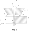
- Figure 1 shows a cutting gas nozzle 1 for laser cutting a plate-shaped metallic workpiece 2 (a sheet) with a thickness D of at least 10 mm using a laser beam 3 and a cutting gas 24 (cf. Fig. 3 ).
- the cutting gas 24 and the laser beam 3 both emerge together from a nozzle opening 5 of the cutting gas nozzle 1.
- the laser beam 3 has a beam direction 6 , which runs along the negative Z direction of an XYZ coordinate system.
- the laser cutting process is a flame cutting process in which oxygen is used as the cutting gas.
- the cutting gas nozzle 1 is moved over the workpiece 2 in the cutting direction 7 , which corresponds to the X direction of the XYZ coordinate system, in order to create a cutting gap in the workpiece 2.
- a distance A of a workpiece-side nozzle end face 8 to the workpiece surface 9 facing the cutting gas nozzle 1 is at least 2 mm, preferably at least 3 mm, in particular at least 5 mm.
- a focus position F in the beam direction 6 of the laser beam 3 is located within the thickness D of the workpiece 2, more precisely in the lower half of the workpiece 2, further away from the cutting gas nozzle 1.
- the focus position F of the laser beam 3 is located in the beam direction 6 in the workpiece 2 at a depth that is greater than half D/2 of the thickness D of the workpiece 2.
- a focus diameter d F at the focus position F in the workpiece 2 is between 150 ⁇ m and 300 ⁇ m, preferably approximately 200 ⁇ m.
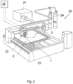
- Figure 3 shows a laser cutting machine 20 suitable for carrying out the flame cutting method described above.
- the laser cutting machine 20 has a solid-state laser or a diode laser as a laser beam generator 21 .
- the laser cutting machine 20 further has a movable (laser) cutting head 22 and a workpiece support 23 on which the workpiece 2 is arranged.
- the laser beam 3 is generated in the laser beam generator 21, which comes from the laser beam generator by means of an optical fiber (not shown). 21 is guided to the cutting head 22.
- the optical fiber is a single-core fiber, ie the optical fiber has only one core in which the laser beam 3 or the laser radiation from the laser beam generator 21 propagates.
- the single core fiber has a core diameter that is between 50 ⁇ m and 150 ⁇ m.
- a multiple core fiber can also be used to guide the laser beam 3 from the laser beam generator 21 to the cutting head 22.
- the laser beam 3 is directed onto the workpiece 2 by means of focusing optics arranged in the cutting head 22.
- the laser beam 3, which emerges from the single core fiber, has a Gaussian intensity profile and maintains this when focusing on the workpiece 2, i.e. the laser beam 3 also has a Gaussian intensity profile on the workpiece surface 9.
- the laser cutting machine 20 is also supplied with cutting gas 24, oxygen or nitrogen shown here as an example.
- oxygen is supplied as cutting gas 24 to the cutting gas nozzle 1 of the cutting head 22, at an overpressure of approximately 0.4-1.0 bar before the cutting gas 24 emerges from the cutting gas nozzle 1.
- the laser cutting machine 20 also includes a machine control 25, which is programmed to move the cutting head 22 together with its cutting gas nozzle 1 relative to the stationary workpiece 2 according to a cutting contour.
- the machine control 25 also controls the power of the laser beam generator 21, which is more than 10 kW in the flame cutting process described above and which can possibly be up to 20 kW or more. In this way, for example, a cutting speed (feed) of 3.1 m/min can be achieved with a workpiece thickness of 15 mm and a cutting speed of 1.75 m/min with a workpiece thickness of 25 mm, with the cutting speed increasing with increasing laser power.
Landscapes
- Physics & Mathematics (AREA)
- Optics & Photonics (AREA)
- Engineering & Computer Science (AREA)
- Plasma & Fusion (AREA)
- Mechanical Engineering (AREA)
- Laser Beam Processing (AREA)
Applications Claiming Priority (2)
| Application Number | Priority Date | Filing Date | Title |
|---|---|---|---|
| DE102019212360.0A DE102019212360A1 (de) | 2019-08-19 | 2019-08-19 | Verfahren zum Brennschneiden mittels eines Laserstrahls |
| PCT/EP2020/069043 WO2021032355A1 (de) | 2019-08-19 | 2020-07-06 | Verfahren zum brennschneiden mittels eines laserstrahls |
Publications (2)
| Publication Number | Publication Date |
|---|---|
| EP4017674A1 EP4017674A1 (de) | 2022-06-29 |
| EP4017674B1 true EP4017674B1 (de) | 2023-11-22 |
Family
ID=71579565
Family Applications (1)
| Application Number | Title | Priority Date | Filing Date |
|---|---|---|---|
| EP20739602.9A Active EP4017674B1 (de) | 2019-08-19 | 2020-07-06 | Verfahren zum brennschneiden mittels eines laserstrahls |
Country Status (6)
| Country | Link |
|---|---|
| US (1) | US20220168841A1 (pl) |
| EP (1) | EP4017674B1 (pl) |
| CN (1) | CN114269508B (pl) |
| DE (1) | DE102019212360A1 (pl) |
| PL (1) | PL4017674T3 (pl) |
| WO (1) | WO2021032355A1 (pl) |
Families Citing this family (7)
| Publication number | Priority date | Publication date | Assignee | Title |
|---|---|---|---|---|
| EP4201576B1 (en) | 2021-12-22 | 2025-03-05 | Bystronic Laser AG | Method for laser reactive cutting a thick metal workpiece; corresponding machine |
| CN114985974A (zh) * | 2022-06-16 | 2022-09-02 | 西北工业大学太仓长三角研究院 | 一种厚板万瓦级激光亮面切割方法 |
| CN114871593A (zh) * | 2022-06-16 | 2022-08-09 | 西北工业大学太仓长三角研究院 | 一种厚板万瓦级光纤激光双组分气体辅助切割方法 |
| CN115519259B (zh) * | 2022-10-22 | 2024-05-24 | 长沙大科激光科技有限公司 | 一种高频电流辅助双光束激光切割方法 |
| CN117283140A (zh) * | 2022-12-14 | 2023-12-26 | 江苏乐希激光装备有限公司 | 一种火焰辅助多焦点激光切割方法及装置 |
| DE102023108555A1 (de) * | 2023-04-04 | 2024-10-10 | TRUMPF Werkzeugmaschinen SE + Co. KG | Düse für eine laserschneideinrichtung sowie verfahren zum laserschneiden eines werkstücks |
| CN116551231B (zh) * | 2023-07-05 | 2023-09-26 | 岗春激光科技(江苏)有限公司 | 一种激光-火焰复合切割装置 |
Citations (8)
| Publication number | Priority date | Publication date | Assignee | Title |
|---|---|---|---|---|
| DE4215561A1 (de) | 1991-11-19 | 1993-05-27 | Fraunhofer Ges Forschung | Verfahren zum abtragen von werkstoff von relativbewegten metallenen werkstuecken |
| US7283714B1 (en) | 2006-12-15 | 2007-10-16 | Ipg Photonics Corporation | Large mode area fiber for low-loss transmission and amplification of single mode lasers |
| WO2009007708A2 (en) | 2007-07-09 | 2009-01-15 | The University Of Manchester | Laser cutting |
| US20090218326A1 (en) | 2006-02-03 | 2009-09-03 | L'air Liquide Societe Anonyme Pour L'eploitation Des Procedes Georges Cladue | Cutting method using a laser having at least one ytterbium-based fiber, in which at least the power of the laser source, the diameter of the focused beam and the beam quality factor are controlled |
| WO2011027065A1 (fr) | 2009-09-01 | 2011-03-10 | L'air Liquide, Societe Anonyme Pour L'etude Et L'exploitation Des Procedes Georges Claude | Tete de focalisation laser avec des lentilles en zns ayant une epaisseur aux bords d'au moins 5 mm; installation et procede de coupage laser employant une telle tete de focalisation |
| EP2399703A1 (en) | 2009-02-23 | 2011-12-28 | Koike Sanso Kogyo Co., Ltd. | Laser cutting method and laser cutting equipment |
| DE102018000443A1 (de) | 2017-01-19 | 2018-07-19 | Fanuc Corporation | Düse für einen Laserbearbeitungskopf |
| US20190176270A1 (en) | 2016-05-18 | 2019-06-13 | Amada Holdings Co., Ltd. | Laser cutting and machining method for plated steel plate, laser cut-and-machined product, thermal cutting and machining method, thermal cut-and-machined product, surface-treated steel plate, laser cutting method, and laser machining head |
Family Cites Families (13)
| Publication number | Priority date | Publication date | Assignee | Title |
|---|---|---|---|---|
| FR2893873B1 (fr) * | 2005-11-25 | 2008-12-12 | Air Liquide | Procede de coupage avec un laser a fibre d'acier inoxydable |
| DE102008053397B4 (de) * | 2008-05-20 | 2012-12-27 | Fraunhofer-Gesellschaft zur Förderung der angewandten Forschung e.V. | Verfahren zum Schmelzschneiden von Werkstücken mit Laserstrahlung |
| JP5361999B2 (ja) * | 2009-05-25 | 2013-12-04 | 三菱電機株式会社 | レーザ加工装置およびレーザ加工方法 |
| DE102009060908A1 (de) * | 2009-12-31 | 2011-07-07 | Volkswagen AG, 38440 | Laserschneiden eines metallischen Werkstücks |
| DE102010003750A1 (de) | 2010-04-08 | 2011-10-13 | Trumpf Laser- Und Systemtechnik Gmbh | Verfahren und Anordnung zum Verändern der Strahlprofilcharakteristik eines Laserstrahls mittels einer Mehrfachclad-Faser |
| DE102010029791A1 (de) * | 2010-06-08 | 2011-12-08 | Trumpf Werkzeugmaschinen Gmbh + Co. Kg | Verfahren zur Lasermaterialbearbeitung eines Werkstücks |
| CN102145412B (zh) * | 2011-03-24 | 2013-08-21 | 湖南泰嘉新材料科技股份有限公司 | 激光切割双金属带锯齿无磨削一次成形方法 |
| DE102012219074A1 (de) | 2012-10-19 | 2014-04-24 | Trumpf Werkzeugmaschinen Gmbh + Co. Kg | Laserschneidmaschine und Verfahren zum Schneiden von Werkstücken unterschiedlicher Dicke |
| JP5364856B1 (ja) * | 2013-02-27 | 2013-12-11 | 三菱重工業株式会社 | 加工装置、加工方法 |
| CN205684910U (zh) * | 2016-04-28 | 2016-11-16 | 北京万恒镭特机电设备有限公司 | 一种内部多层激光切划装置 |
| DE102016215019C5 (de) * | 2016-08-11 | 2023-04-06 | Trumpf Werkzeugmaschinen Gmbh + Co. Kg | Verfahren zum Laserschneiden mit optimierter Gasdynamik |
| DE102016220807B3 (de) * | 2016-10-24 | 2018-03-29 | Trumpf Werkzeugmaschinen Gmbh + Co. Kg | Verfahren zum Schneiden eines Werkstücks mittels eines Laserstrahls |
| JP6577110B2 (ja) * | 2017-10-06 | 2019-09-18 | 株式会社アマダホールディングス | レーザ加工方法及びレーザ加工装置 |
-
2019
- 2019-08-19 DE DE102019212360.0A patent/DE102019212360A1/de active Pending
-
2020
- 2020-07-06 WO PCT/EP2020/069043 patent/WO2021032355A1/de not_active Ceased
- 2020-07-06 CN CN202080058983.8A patent/CN114269508B/zh active Active
- 2020-07-06 PL PL20739602.9T patent/PL4017674T3/pl unknown
- 2020-07-06 EP EP20739602.9A patent/EP4017674B1/de active Active
-
2022
- 2022-02-18 US US17/675,621 patent/US20220168841A1/en active Pending
Patent Citations (8)
| Publication number | Priority date | Publication date | Assignee | Title |
|---|---|---|---|---|
| DE4215561A1 (de) | 1991-11-19 | 1993-05-27 | Fraunhofer Ges Forschung | Verfahren zum abtragen von werkstoff von relativbewegten metallenen werkstuecken |
| US20090218326A1 (en) | 2006-02-03 | 2009-09-03 | L'air Liquide Societe Anonyme Pour L'eploitation Des Procedes Georges Cladue | Cutting method using a laser having at least one ytterbium-based fiber, in which at least the power of the laser source, the diameter of the focused beam and the beam quality factor are controlled |
| US7283714B1 (en) | 2006-12-15 | 2007-10-16 | Ipg Photonics Corporation | Large mode area fiber for low-loss transmission and amplification of single mode lasers |
| WO2009007708A2 (en) | 2007-07-09 | 2009-01-15 | The University Of Manchester | Laser cutting |
| EP2399703A1 (en) | 2009-02-23 | 2011-12-28 | Koike Sanso Kogyo Co., Ltd. | Laser cutting method and laser cutting equipment |
| WO2011027065A1 (fr) | 2009-09-01 | 2011-03-10 | L'air Liquide, Societe Anonyme Pour L'etude Et L'exploitation Des Procedes Georges Claude | Tete de focalisation laser avec des lentilles en zns ayant une epaisseur aux bords d'au moins 5 mm; installation et procede de coupage laser employant une telle tete de focalisation |
| US20190176270A1 (en) | 2016-05-18 | 2019-06-13 | Amada Holdings Co., Ltd. | Laser cutting and machining method for plated steel plate, laser cut-and-machined product, thermal cutting and machining method, thermal cut-and-machined product, surface-treated steel plate, laser cutting method, and laser machining head |
| DE102018000443A1 (de) | 2017-01-19 | 2018-07-19 | Fanuc Corporation | Düse für einen Laserbearbeitungskopf |
Also Published As
| Publication number | Publication date |
|---|---|
| DE102019212360A1 (de) | 2021-02-25 |
| PL4017674T3 (pl) | 2024-04-15 |
| EP4017674A1 (de) | 2022-06-29 |
| US20220168841A1 (en) | 2022-06-02 |
| WO2021032355A1 (de) | 2021-02-25 |
| CN114269508B (zh) | 2025-09-09 |
| CN114269508A (zh) | 2022-04-01 |
Similar Documents
| Publication | Publication Date | Title |
|---|---|---|
| EP4017674B1 (de) | Verfahren zum brennschneiden mittels eines laserstrahls | |
| EP3315243B1 (de) | Verfahren zum laserschneiden mit optimierter gasdynamik | |
| EP4035823B1 (de) | Prozess zur strahlbearbeitung eines platten- oder rohrförmigen werkstücks | |
| EP4200101B1 (de) | Verfahren zur herstellung mindestens eines werkstückteils und eines restwerkstücks aus einem werkstück | |
| EP3965990B1 (de) | Verfahren und strahlbearbeitungsvorrichtung zur strahlbearbeitung eines werkstücks | |
| EP0993345B1 (de) | Verfahren zum biegen mit laserunterstützung | |
| WO2021228829A1 (de) | Laserschneidverfahren und laserschneidanlage | |
| EP4526076A1 (de) | Technik zum erzeugen einer kantenverrundung | |
| WO2023072568A1 (de) | Verfahren zur herstellung von werkstückteilen mit angefasten schnittkanten | |
| DE102013210845B4 (de) | Verfahren zum Einstechen in metallische Werkstücke mittels eines Laserstrahls | |
| DE102022101092A1 (de) | Verfahren zur Laserbearbeitung eines Werkstücks mit verringerter Intensitätslücke | |
| WO2023061831A1 (de) | Verfahren zur laserbearbeitung eines werkstücks mit verringerter intensitätslücke | |
| DE102022112050A1 (de) | Düse für die Laserbearbeitung mit hohen Fokuslagen | |
| WO2022063647A1 (de) | Verfahren zum laserschneiden | |
| WO2023036898A1 (de) | Laserschneidverfahren zum erzeugen von nanojoints | |
| DE102021126755A1 (de) | Verfahren zur Laserbearbeitung eines Werkstücks, mit verringerter Intensitätslücke | |
| EP4215308B1 (de) | Laserschneideverfahren mit fokuslage innerhalb einer schneiddüse mit kleinem mündungsdurchmesser | |
| DE102021119750A1 (de) | Verfahren zum Laserschneiden eines Werkstücks, mit über die Dicke des Werkstücks ausgedehntem Intensitätsminimum im Zentrum des Intensitätsprofils des Laserstrahls | |
| EP3736074A1 (de) | Verfahren zum trennenden schneiden einer mehrzahl von werkstückteilen | |
| DE102024112208A1 (de) | Verfahren und Laserschneidevorrichtung zum Erzeugen einer Fase an einem Schnittspalt in einem Werkstück mittels eines Laserschneidkopfes | |
| DE102023113667A1 (de) | Technik zum Erzeugen eines Haltestegs beim Laserbrennschneiden | |
| WO2025099150A1 (de) | Verfahren und vorrichtung zum schneiden eines werkstücks mittels eines laserstrahls | |
| DE102022128170A1 (de) | Technik zum Verrunden einer Werkstückkante | |
| DE10128609A1 (de) | Anordnung zur Verstellung des Fokusradius und der Rayleighlänge für die Laserstrahlbearbeitung, insbesonere in einer Laserschneidmaschine | |
| DE102022125138A1 (de) | Verfahren zum Laserschneiden plattenförmiger Werkstücke und zugehöriges Computerprogrammprodukt |
Legal Events
| Date | Code | Title | Description |
|---|---|---|---|
| STAA | Information on the status of an ep patent application or granted ep patent |
Free format text: STATUS: UNKNOWN |
|
| STAA | Information on the status of an ep patent application or granted ep patent |
Free format text: STATUS: THE INTERNATIONAL PUBLICATION HAS BEEN MADE |
|
| PUAI | Public reference made under article 153(3) epc to a published international application that has entered the european phase |
Free format text: ORIGINAL CODE: 0009012 |
|
| STAA | Information on the status of an ep patent application or granted ep patent |
Free format text: STATUS: REQUEST FOR EXAMINATION WAS MADE |
|
| 17P | Request for examination filed |
Effective date: 20220316 |
|
| AK | Designated contracting states |
Kind code of ref document: A1 Designated state(s): AL AT BE BG CH CY CZ DE DK EE ES FI FR GB GR HR HU IE IS IT LI LT LU LV MC MK MT NL NO PL PT RO RS SE SI SK SM TR |
|
| DAV | Request for validation of the european patent (deleted) | ||
| DAX | Request for extension of the european patent (deleted) | ||
| RAP3 | Party data changed (applicant data changed or rights of an application transferred) |
Owner name: TRUMPF WERKZEUGMASCHINEN SE + CO. KG |
|
| GRAP | Despatch of communication of intention to grant a patent |
Free format text: ORIGINAL CODE: EPIDOSNIGR1 |
|
| STAA | Information on the status of an ep patent application or granted ep patent |
Free format text: STATUS: GRANT OF PATENT IS INTENDED |
|
| INTG | Intention to grant announced |
Effective date: 20230626 |
|
| GRAS | Grant fee paid |
Free format text: ORIGINAL CODE: EPIDOSNIGR3 |
|
| GRAA | (expected) grant |
Free format text: ORIGINAL CODE: 0009210 |
|
| STAA | Information on the status of an ep patent application or granted ep patent |
Free format text: STATUS: THE PATENT HAS BEEN GRANTED |
|
| AK | Designated contracting states |
Kind code of ref document: B1 Designated state(s): AL AT BE BG CH CY CZ DE DK EE ES FI FR GB GR HR HU IE IS IT LI LT LU LV MC MK MT NL NO PL PT RO RS SE SI SK SM TR |
|
| REG | Reference to a national code |
Ref country code: GB Ref legal event code: FG4D Free format text: NOT ENGLISH |
|
| REG | Reference to a national code |
Ref country code: CH Ref legal event code: EP Ref country code: DE Ref legal event code: R096 Ref document number: 502020006138 Country of ref document: DE |
|
| REG | Reference to a national code |
Ref country code: IE Ref legal event code: FG4D Free format text: LANGUAGE OF EP DOCUMENT: GERMAN |
|
| REG | Reference to a national code |
Ref country code: LT Ref legal event code: MG9D |
|
| REG | Reference to a national code |
Ref country code: NL Ref legal event code: MP Effective date: 20231122 |
|
| PG25 | Lapsed in a contracting state [announced via postgrant information from national office to epo] |
Ref country code: GR Free format text: LAPSE BECAUSE OF FAILURE TO SUBMIT A TRANSLATION OF THE DESCRIPTION OR TO PAY THE FEE WITHIN THE PRESCRIBED TIME-LIMIT Effective date: 20240223 |
|
| PG25 | Lapsed in a contracting state [announced via postgrant information from national office to epo] |
Ref country code: IS Free format text: LAPSE BECAUSE OF FAILURE TO SUBMIT A TRANSLATION OF THE DESCRIPTION OR TO PAY THE FEE WITHIN THE PRESCRIBED TIME-LIMIT Effective date: 20240322 |
|
| PG25 | Lapsed in a contracting state [announced via postgrant information from national office to epo] |
Ref country code: LT Free format text: LAPSE BECAUSE OF FAILURE TO SUBMIT A TRANSLATION OF THE DESCRIPTION OR TO PAY THE FEE WITHIN THE PRESCRIBED TIME-LIMIT Effective date: 20231122 |
|
| PG25 | Lapsed in a contracting state [announced via postgrant information from national office to epo] |
Ref country code: NL Free format text: LAPSE BECAUSE OF FAILURE TO SUBMIT A TRANSLATION OF THE DESCRIPTION OR TO PAY THE FEE WITHIN THE PRESCRIBED TIME-LIMIT Effective date: 20231122 |
|
| PG25 | Lapsed in a contracting state [announced via postgrant information from national office to epo] |
Ref country code: ES Free format text: LAPSE BECAUSE OF FAILURE TO SUBMIT A TRANSLATION OF THE DESCRIPTION OR TO PAY THE FEE WITHIN THE PRESCRIBED TIME-LIMIT Effective date: 20231122 |
|
| PG25 | Lapsed in a contracting state [announced via postgrant information from national office to epo] |
Ref country code: NL Free format text: LAPSE BECAUSE OF FAILURE TO SUBMIT A TRANSLATION OF THE DESCRIPTION OR TO PAY THE FEE WITHIN THE PRESCRIBED TIME-LIMIT Effective date: 20231122 Ref country code: LT Free format text: LAPSE BECAUSE OF FAILURE TO SUBMIT A TRANSLATION OF THE DESCRIPTION OR TO PAY THE FEE WITHIN THE PRESCRIBED TIME-LIMIT Effective date: 20231122 Ref country code: IS Free format text: LAPSE BECAUSE OF FAILURE TO SUBMIT A TRANSLATION OF THE DESCRIPTION OR TO PAY THE FEE WITHIN THE PRESCRIBED TIME-LIMIT Effective date: 20240322 Ref country code: GR Free format text: LAPSE BECAUSE OF FAILURE TO SUBMIT A TRANSLATION OF THE DESCRIPTION OR TO PAY THE FEE WITHIN THE PRESCRIBED TIME-LIMIT Effective date: 20240223 Ref country code: ES Free format text: LAPSE BECAUSE OF FAILURE TO SUBMIT A TRANSLATION OF THE DESCRIPTION OR TO PAY THE FEE WITHIN THE PRESCRIBED TIME-LIMIT Effective date: 20231122 Ref country code: BG Free format text: LAPSE BECAUSE OF FAILURE TO SUBMIT A TRANSLATION OF THE DESCRIPTION OR TO PAY THE FEE WITHIN THE PRESCRIBED TIME-LIMIT Effective date: 20240222 Ref country code: PT Free format text: LAPSE BECAUSE OF FAILURE TO SUBMIT A TRANSLATION OF THE DESCRIPTION OR TO PAY THE FEE WITHIN THE PRESCRIBED TIME-LIMIT Effective date: 20240322 |
|
| PG25 | Lapsed in a contracting state [announced via postgrant information from national office to epo] |
Ref country code: SE Free format text: LAPSE BECAUSE OF FAILURE TO SUBMIT A TRANSLATION OF THE DESCRIPTION OR TO PAY THE FEE WITHIN THE PRESCRIBED TIME-LIMIT Effective date: 20231122 Ref country code: RS Free format text: LAPSE BECAUSE OF FAILURE TO SUBMIT A TRANSLATION OF THE DESCRIPTION OR TO PAY THE FEE WITHIN THE PRESCRIBED TIME-LIMIT Effective date: 20231122 Ref country code: NO Free format text: LAPSE BECAUSE OF FAILURE TO SUBMIT A TRANSLATION OF THE DESCRIPTION OR TO PAY THE FEE WITHIN THE PRESCRIBED TIME-LIMIT Effective date: 20240222 Ref country code: LV Free format text: LAPSE BECAUSE OF FAILURE TO SUBMIT A TRANSLATION OF THE DESCRIPTION OR TO PAY THE FEE WITHIN THE PRESCRIBED TIME-LIMIT Effective date: 20231122 Ref country code: HR Free format text: LAPSE BECAUSE OF FAILURE TO SUBMIT A TRANSLATION OF THE DESCRIPTION OR TO PAY THE FEE WITHIN THE PRESCRIBED TIME-LIMIT Effective date: 20231122 |
|
| PG25 | Lapsed in a contracting state [announced via postgrant information from national office to epo] |
Ref country code: DK Free format text: LAPSE BECAUSE OF FAILURE TO SUBMIT A TRANSLATION OF THE DESCRIPTION OR TO PAY THE FEE WITHIN THE PRESCRIBED TIME-LIMIT Effective date: 20231122 |
|
| PG25 | Lapsed in a contracting state [announced via postgrant information from national office to epo] |
Ref country code: CZ Free format text: LAPSE BECAUSE OF FAILURE TO SUBMIT A TRANSLATION OF THE DESCRIPTION OR TO PAY THE FEE WITHIN THE PRESCRIBED TIME-LIMIT Effective date: 20231122 |
|
| PG25 | Lapsed in a contracting state [announced via postgrant information from national office to epo] |
Ref country code: SK Free format text: LAPSE BECAUSE OF FAILURE TO SUBMIT A TRANSLATION OF THE DESCRIPTION OR TO PAY THE FEE WITHIN THE PRESCRIBED TIME-LIMIT Effective date: 20231122 |
|
| PG25 | Lapsed in a contracting state [announced via postgrant information from national office to epo] |
Ref country code: SM Free format text: LAPSE BECAUSE OF FAILURE TO SUBMIT A TRANSLATION OF THE DESCRIPTION OR TO PAY THE FEE WITHIN THE PRESCRIBED TIME-LIMIT Effective date: 20231122 Ref country code: SK Free format text: LAPSE BECAUSE OF FAILURE TO SUBMIT A TRANSLATION OF THE DESCRIPTION OR TO PAY THE FEE WITHIN THE PRESCRIBED TIME-LIMIT Effective date: 20231122 Ref country code: RO Free format text: LAPSE BECAUSE OF FAILURE TO SUBMIT A TRANSLATION OF THE DESCRIPTION OR TO PAY THE FEE WITHIN THE PRESCRIBED TIME-LIMIT Effective date: 20231122 Ref country code: EE Free format text: LAPSE BECAUSE OF FAILURE TO SUBMIT A TRANSLATION OF THE DESCRIPTION OR TO PAY THE FEE WITHIN THE PRESCRIBED TIME-LIMIT Effective date: 20231122 Ref country code: DK Free format text: LAPSE BECAUSE OF FAILURE TO SUBMIT A TRANSLATION OF THE DESCRIPTION OR TO PAY THE FEE WITHIN THE PRESCRIBED TIME-LIMIT Effective date: 20231122 Ref country code: CZ Free format text: LAPSE BECAUSE OF FAILURE TO SUBMIT A TRANSLATION OF THE DESCRIPTION OR TO PAY THE FEE WITHIN THE PRESCRIBED TIME-LIMIT Effective date: 20231122 |
|
| REG | Reference to a national code |
Ref country code: DE Ref legal event code: R026 Ref document number: 502020006138 Country of ref document: DE |
|
| PLBI | Opposition filed |
Free format text: ORIGINAL CODE: 0009260 |
|
| PLAX | Notice of opposition and request to file observation + time limit sent |
Free format text: ORIGINAL CODE: EPIDOSNOBS2 |
|
| 26 | Opposition filed |
Opponent name: BYSTRONIC LASER AG Effective date: 20240821 |
|
| PG25 | Lapsed in a contracting state [announced via postgrant information from national office to epo] |
Ref country code: SI Free format text: LAPSE BECAUSE OF FAILURE TO SUBMIT A TRANSLATION OF THE DESCRIPTION OR TO PAY THE FEE WITHIN THE PRESCRIBED TIME-LIMIT Effective date: 20231122 |
|
| PG25 | Lapsed in a contracting state [announced via postgrant information from national office to epo] |
Ref country code: SI Free format text: LAPSE BECAUSE OF FAILURE TO SUBMIT A TRANSLATION OF THE DESCRIPTION OR TO PAY THE FEE WITHIN THE PRESCRIBED TIME-LIMIT Effective date: 20231122 |
|
| PLBP | Opposition withdrawn |
Free format text: ORIGINAL CODE: 0009264 |
|
| PLBD | Termination of opposition procedure: decision despatched |
Free format text: ORIGINAL CODE: EPIDOSNOPC1 |
|
| REG | Reference to a national code |
Ref country code: DE Ref legal event code: R100 Ref document number: 502020006138 Country of ref document: DE |
|
| PG25 | Lapsed in a contracting state [announced via postgrant information from national office to epo] |
Ref country code: MC Free format text: LAPSE BECAUSE OF FAILURE TO SUBMIT A TRANSLATION OF THE DESCRIPTION OR TO PAY THE FEE WITHIN THE PRESCRIBED TIME-LIMIT Effective date: 20231122 |
|
| REG | Reference to a national code |
Ref country code: CH Ref legal event code: PL |
|
| PG25 | Lapsed in a contracting state [announced via postgrant information from national office to epo] |
Ref country code: LU Free format text: LAPSE BECAUSE OF NON-PAYMENT OF DUE FEES Effective date: 20240706 |
|
| GBPC | Gb: european patent ceased through non-payment of renewal fee |
Effective date: 20240706 |
|
| PG25 | Lapsed in a contracting state [announced via postgrant information from national office to epo] |
Ref country code: LU Free format text: LAPSE BECAUSE OF NON-PAYMENT OF DUE FEES Effective date: 20240706 |
|
| PG25 | Lapsed in a contracting state [announced via postgrant information from national office to epo] |
Ref country code: CH Free format text: LAPSE BECAUSE OF NON-PAYMENT OF DUE FEES Effective date: 20240731 Ref country code: BE Free format text: LAPSE BECAUSE OF NON-PAYMENT OF DUE FEES Effective date: 20240731 |
|
| PG25 | Lapsed in a contracting state [announced via postgrant information from national office to epo] |
Ref country code: FR Free format text: LAPSE BECAUSE OF NON-PAYMENT OF DUE FEES Effective date: 20240731 |
|
| PLBM | Termination of opposition procedure: date of legal effect published |
Free format text: ORIGINAL CODE: 0009276 |
|
| PG25 | Lapsed in a contracting state [announced via postgrant information from national office to epo] |
Ref country code: GB Free format text: LAPSE BECAUSE OF NON-PAYMENT OF DUE FEES Effective date: 20240706 |
|
| 27C | Opposition proceedings terminated |
Effective date: 20250120 |
|
| REG | Reference to a national code |
Ref country code: BE Ref legal event code: MM Effective date: 20240731 |
|
| PGFP | Annual fee paid to national office [announced via postgrant information from national office to epo] |
Ref country code: PL Payment date: 20250620 Year of fee payment: 6 |
|
| PG25 | Lapsed in a contracting state [announced via postgrant information from national office to epo] |
Ref country code: IE Free format text: LAPSE BECAUSE OF NON-PAYMENT OF DUE FEES Effective date: 20240706 |
|
| PG25 | Lapsed in a contracting state [announced via postgrant information from national office to epo] |
Ref country code: FI Free format text: LAPSE BECAUSE OF FAILURE TO SUBMIT A TRANSLATION OF THE DESCRIPTION OR TO PAY THE FEE WITHIN THE PRESCRIBED TIME-LIMIT Effective date: 20231122 |
|
| PGFP | Annual fee paid to national office [announced via postgrant information from national office to epo] |
Ref country code: DE Payment date: 20250722 Year of fee payment: 6 |
|
| PGFP | Annual fee paid to national office [announced via postgrant information from national office to epo] |
Ref country code: IT Payment date: 20250724 Year of fee payment: 6 |
|
| PGFP | Annual fee paid to national office [announced via postgrant information from national office to epo] |
Ref country code: AT Payment date: 20251020 Year of fee payment: 5 |
|
| PG25 | Lapsed in a contracting state [announced via postgrant information from national office to epo] |
Ref country code: CY Free format text: LAPSE BECAUSE OF FAILURE TO SUBMIT A TRANSLATION OF THE DESCRIPTION OR TO PAY THE FEE WITHIN THE PRESCRIBED TIME-LIMIT; INVALID AB INITIO Effective date: 20200706 |
|
| PG25 | Lapsed in a contracting state [announced via postgrant information from national office to epo] |
Ref country code: HU Free format text: LAPSE BECAUSE OF FAILURE TO SUBMIT A TRANSLATION OF THE DESCRIPTION OR TO PAY THE FEE WITHIN THE PRESCRIBED TIME-LIMIT; INVALID AB INITIO Effective date: 20200706 |