EP4017674B1 - Method for flame cutting by means of a laser beam - Google Patents
Method for flame cutting by means of a laser beam Download PDFInfo
- Publication number
- EP4017674B1 EP4017674B1 EP20739602.9A EP20739602A EP4017674B1 EP 4017674 B1 EP4017674 B1 EP 4017674B1 EP 20739602 A EP20739602 A EP 20739602A EP 4017674 B1 EP4017674 B1 EP 4017674B1
- Authority
- EP
- European Patent Office
- Prior art keywords
- cutting
- laser beam
- workpiece
- laser
- nozzle
- Prior art date
- Legal status (The legal status is an assumption and is not a legal conclusion. Google has not performed a legal analysis and makes no representation as to the accuracy of the status listed.)
- Active
Links
- 238000005520 cutting process Methods 0.000 title claims description 91
- 238000000034 method Methods 0.000 title claims description 23
- 239000007789 gas Substances 0.000 claims description 35
- 239000000835 fiber Substances 0.000 claims description 19
- 238000003698 laser cutting Methods 0.000 claims description 15
- 239000013307 optical fiber Substances 0.000 claims description 13
- QVGXLLKOCUKJST-UHFFFAOYSA-N atomic oxygen Chemical compound [O] QVGXLLKOCUKJST-UHFFFAOYSA-N 0.000 claims description 10
- 239000001301 oxygen Substances 0.000 claims description 10
- 229910052760 oxygen Inorganic materials 0.000 claims description 10
- 239000002184 metal Substances 0.000 description 7
- IJGRMHOSHXDMSA-UHFFFAOYSA-N Atomic nitrogen Chemical compound N#N IJGRMHOSHXDMSA-UHFFFAOYSA-N 0.000 description 2
- OKTJSMMVPCPJKN-UHFFFAOYSA-N Carbon Chemical compound [C] OKTJSMMVPCPJKN-UHFFFAOYSA-N 0.000 description 1
- 230000009286 beneficial effect Effects 0.000 description 1
- 238000002485 combustion reaction Methods 0.000 description 1
- 230000000694 effects Effects 0.000 description 1
- 230000002349 favourable effect Effects 0.000 description 1
- 239000000463 material Substances 0.000 description 1
- 229910052757 nitrogen Inorganic materials 0.000 description 1
- 230000003287 optical effect Effects 0.000 description 1
- 230000005855 radiation Effects 0.000 description 1
- 239000002893 slag Substances 0.000 description 1
Images

Classifications
-
- B—PERFORMING OPERATIONS; TRANSPORTING
- B23—MACHINE TOOLS; METAL-WORKING NOT OTHERWISE PROVIDED FOR
- B23K—SOLDERING OR UNSOLDERING; WELDING; CLADDING OR PLATING BY SOLDERING OR WELDING; CUTTING BY APPLYING HEAT LOCALLY, e.g. FLAME CUTTING; WORKING BY LASER BEAM
- B23K26/00—Working by laser beam, e.g. welding, cutting or boring
- B23K26/02—Positioning or observing the workpiece, e.g. with respect to the point of impact; Aligning, aiming or focusing the laser beam
- B23K26/04—Automatically aligning, aiming or focusing the laser beam, e.g. using the back-scattered light
-
- B—PERFORMING OPERATIONS; TRANSPORTING
- B23—MACHINE TOOLS; METAL-WORKING NOT OTHERWISE PROVIDED FOR
- B23K—SOLDERING OR UNSOLDERING; WELDING; CLADDING OR PLATING BY SOLDERING OR WELDING; CUTTING BY APPLYING HEAT LOCALLY, e.g. FLAME CUTTING; WORKING BY LASER BEAM
- B23K26/00—Working by laser beam, e.g. welding, cutting or boring
- B23K26/08—Devices involving relative movement between laser beam and workpiece
- B23K26/0869—Devices involving movement of the laser head in at least one axial direction
- B23K26/0876—Devices involving movement of the laser head in at least one axial direction in at least two axial directions
-
- B—PERFORMING OPERATIONS; TRANSPORTING
- B23—MACHINE TOOLS; METAL-WORKING NOT OTHERWISE PROVIDED FOR
- B23K—SOLDERING OR UNSOLDERING; WELDING; CLADDING OR PLATING BY SOLDERING OR WELDING; CUTTING BY APPLYING HEAT LOCALLY, e.g. FLAME CUTTING; WORKING BY LASER BEAM
- B23K26/00—Working by laser beam, e.g. welding, cutting or boring
- B23K26/02—Positioning or observing the workpiece, e.g. with respect to the point of impact; Aligning, aiming or focusing the laser beam
- B23K26/04—Automatically aligning, aiming or focusing the laser beam, e.g. using the back-scattered light
- B23K26/046—Automatically focusing the laser beam
-
- B—PERFORMING OPERATIONS; TRANSPORTING
- B23—MACHINE TOOLS; METAL-WORKING NOT OTHERWISE PROVIDED FOR
- B23K—SOLDERING OR UNSOLDERING; WELDING; CLADDING OR PLATING BY SOLDERING OR WELDING; CUTTING BY APPLYING HEAT LOCALLY, e.g. FLAME CUTTING; WORKING BY LASER BEAM
- B23K26/00—Working by laser beam, e.g. welding, cutting or boring
- B23K26/36—Removing material
- B23K26/38—Removing material by boring or cutting
-
- B—PERFORMING OPERATIONS; TRANSPORTING
- B23—MACHINE TOOLS; METAL-WORKING NOT OTHERWISE PROVIDED FOR
- B23K—SOLDERING OR UNSOLDERING; WELDING; CLADDING OR PLATING BY SOLDERING OR WELDING; CUTTING BY APPLYING HEAT LOCALLY, e.g. FLAME CUTTING; WORKING BY LASER BEAM
- B23K2101/00—Articles made by soldering, welding or cutting
- B23K2101/18—Sheet panels
Definitions
- the invention relates to a method for flame cutting a particularly plate-shaped workpiece with a thickness of at least 10 mm using a laser beam with a power of more than 10 kW and with oxygen as the cutting gas.
- the laser beam is typically moved along a (usually variable) cutting direction relative to the workpiece, with a cutting gap forming in the workpiece counter to the cutting direction.
- a comparatively large focus diameter of the processing laser beam is usually required he wishes.
- the cutting gap should be wide enough so that any liquefied workpiece material and/or slag produced during cutting can be blown out.
- a comparatively small focus diameter is desired.
- the focus position of the laser beam should be arranged above the sheet metal surface, in particular at a distance of approximately 4-5 mm from the sheet metal surface.
- a distance between the sheet metal surface and a processing nozzle is between approx. 1 mm and approx. 2 mm.
- the US 2007/119834 A1 discloses a method to increase the cutting speed when laser cutting thick workpieces, but this does not happen via a special adjustment of the focus position. Furthermore, the distance of the cutting nozzle from the workpiece surface is not taken into account.
- the object of the present invention is to provide a method for flame cutting using a laser beam with a laser power of more than 10 kW, in which an increase in the cutting speed can be achieved.
- This task is solved by a method of the type mentioned at the beginning, in which a focus position in the beam direction of the laser beam is in the workpiece is located or positioned at a depth that is greater than half the thickness of the workpiece and at which the laser beam emerges together with the cutting gas from a nozzle opening of a cutting gas nozzle, with a distance between a workpiece-side nozzle end face and the workpiece surface being at least 2 mm, preferably at least 3 mm, particularly preferably at least 5 mm.
- the focus position of the laser beam has a distance with respect to the workpiece surface at which the laser beam enters the workpiece that is greater than half the thickness of the workpiece. If the laser beam hits the workpiece at the top, as is generally the case, the focus position, i.e. the position of the beam waist of the laser beam, is below the center of the workpiece. The focus position is typically not below the workpiece, i.e. the laser beam is focused at a focus position that lies between half the workpiece thickness and the entire workpiece thickness. The greater the thickness of the workpiece, the greater the distance of the focus position from the workpiece surface.
- Such an adjustment of the focus position differs significantly from the previously used settings, in which the focus position was at the top of the workpiece, slightly below the top of the workpiece or above the workpiece (cf. the WO 2009 007708 A2 ) is arranged.
- the focus position is very deep in the workpiece.
- This extremely deep focus position leads to a defocusing of the laser beam on the workpiece surface and thus to a reduction in the power density on the workpiece surface. This is accompanied by a widening of the cutting gap.
- a significant, continuous increase in cutting speed can be achieved while at the same time having good cutting edge quality and process reliability.
- a 50% higher laser power with less than 20% increase in feed.
- a feed increase of 50% can surprisingly also be achieved.
- the inventors have recognized that it is also advantageous for carrying out the method if a very large distance is set between the cutting gas nozzle, more precisely the nozzle end face, and the workpiece surface, since in this way the desired effect, namely an increase in the feed speed, is achieved increasing the power of the laser beam.
- the choice of a large distance between the cutting gas nozzle and the workpiece surface is also contrary to the teaching of WO 2009 007708 A2 , which states that a distance between the nozzle and the top of the workpiece should be between 1 mm and 2 mm.
- the laser beam is generated in a laser beam generator which is connected via an optical fiber to a cutting head to which the cutting gas nozzle is attached, the optical fiber being designed as a single-core fiber or as a multiple-core fiber.
- the optical fiber can be as in the WO 2011 124671 A1 described, that is, it can be designed as a multiple clad fiber with an inner fiber core and with at least one toroidal core.
- the multiple core fiber can also be used as in the WO 2014 060091 A1 described is to be trained.
- the single core fiber has a core diameter between 50 ⁇ m and 150 ⁇ m.
- a core diameter of this size has proven to be advantageous for flame cutting.
- the laser beam emerging from the optical fiber is typically guided by one in the cutting head arranged focusing device, for example in the form of a focusing optics, for example a focusing lens, focused on the workpiece.
- the laser beam has a Gaussian intensity profile on the top side of the workpiece.
- Such an intensity profile has proven to be favorable for flame cutting with the parameters described above.
- the Gaussian intensity profile is typically present when the laser beam emerges from a single core fiber, so that when using such an optical fiber, no additional optical elements are required to generate the Gaussian intensity profile.
- the focus diameter of the laser beam at the focus position is between 150 ⁇ m and 300 ⁇ m, preferably 200 ⁇ m.
- Such a focus diameter has proven to be advantageous for the flame cutting of thick plate-shaped workpieces, especially sheet metal, when the focus position is in the lower half of the workpiece.
- the laser beam is generated using a solid-state laser or using a diode laser as a laser beam generator.
- Solid-state and diode lasers have proven to be beneficial for fast cutting, especially of thin workpieces, and have better energy efficiency than CO2 lasers.
- the area of application of solid-state or diode lasers is sensibly expanded to include flame cutting processes.
- the excess pressure (boiler pressure) of the cutting gas (oxygen) before it exits the nozzle opening is between 0.4 and 1 bar. Due to the higher laser power available of more than 10 kW, less oxygen is required to realize a balanced exothermic combustion process. Too high an oxygen volume would lead to uncontrolled burning out of the cutting gap.
- the object on which the invention is based is further achieved by a laser cutting machine according to claim 8, which is set up to carry out the method according to one of the variants described above.
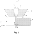
- Figure 1 shows a cutting gas nozzle 1 for laser cutting a plate-shaped metallic workpiece 2 (a sheet) with a thickness D of at least 10 mm using a laser beam 3 and a cutting gas 24 (cf. Fig. 3 ).
- the cutting gas 24 and the laser beam 3 both emerge together from a nozzle opening 5 of the cutting gas nozzle 1.
- the laser beam 3 has a beam direction 6 , which runs along the negative Z direction of an XYZ coordinate system.
- the laser cutting process is a flame cutting process in which oxygen is used as the cutting gas.
- the cutting gas nozzle 1 is moved over the workpiece 2 in the cutting direction 7 , which corresponds to the X direction of the XYZ coordinate system, in order to create a cutting gap in the workpiece 2.
- a distance A of a workpiece-side nozzle end face 8 to the workpiece surface 9 facing the cutting gas nozzle 1 is at least 2 mm, preferably at least 3 mm, in particular at least 5 mm.
- a focus position F in the beam direction 6 of the laser beam 3 is located within the thickness D of the workpiece 2, more precisely in the lower half of the workpiece 2, further away from the cutting gas nozzle 1.
- the focus position F of the laser beam 3 is located in the beam direction 6 in the workpiece 2 at a depth that is greater than half D/2 of the thickness D of the workpiece 2.
- a focus diameter d F at the focus position F in the workpiece 2 is between 150 ⁇ m and 300 ⁇ m, preferably approximately 200 ⁇ m.
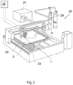
- Figure 3 shows a laser cutting machine 20 suitable for carrying out the flame cutting method described above.
- the laser cutting machine 20 has a solid-state laser or a diode laser as a laser beam generator 21 .
- the laser cutting machine 20 further has a movable (laser) cutting head 22 and a workpiece support 23 on which the workpiece 2 is arranged.
- the laser beam 3 is generated in the laser beam generator 21, which comes from the laser beam generator by means of an optical fiber (not shown). 21 is guided to the cutting head 22.
- the optical fiber is a single-core fiber, ie the optical fiber has only one core in which the laser beam 3 or the laser radiation from the laser beam generator 21 propagates.
- the single core fiber has a core diameter that is between 50 ⁇ m and 150 ⁇ m.
- a multiple core fiber can also be used to guide the laser beam 3 from the laser beam generator 21 to the cutting head 22.
- the laser beam 3 is directed onto the workpiece 2 by means of focusing optics arranged in the cutting head 22.
- the laser beam 3, which emerges from the single core fiber, has a Gaussian intensity profile and maintains this when focusing on the workpiece 2, i.e. the laser beam 3 also has a Gaussian intensity profile on the workpiece surface 9.
- the laser cutting machine 20 is also supplied with cutting gas 24, oxygen or nitrogen shown here as an example.
- oxygen is supplied as cutting gas 24 to the cutting gas nozzle 1 of the cutting head 22, at an overpressure of approximately 0.4-1.0 bar before the cutting gas 24 emerges from the cutting gas nozzle 1.
- the laser cutting machine 20 also includes a machine control 25, which is programmed to move the cutting head 22 together with its cutting gas nozzle 1 relative to the stationary workpiece 2 according to a cutting contour.
- the machine control 25 also controls the power of the laser beam generator 21, which is more than 10 kW in the flame cutting process described above and which can possibly be up to 20 kW or more. In this way, for example, a cutting speed (feed) of 3.1 m/min can be achieved with a workpiece thickness of 15 mm and a cutting speed of 1.75 m/min with a workpiece thickness of 25 mm, with the cutting speed increasing with increasing laser power.
Description
Die Erfindung betrifft ein Verfahren zum Brennschneiden eines insbesondere plattenförmigen Werkstücks mit einer Dicke von mindestens 10 mm mittels eines Laserstrahls mit einer Leistung von mehr als 10 kW und mit Sauerstoff als Schneidgas. Bei einem solchen Verfahren zum Brennschneiden wird der Laserstrahl typischerweise entlang einer (in der Regel veränderlichen) Schneidrichtung relativ zum Werkstück bewegt, wobei sich entgegen der Schneidrichtung ein Schnittspalt in dem Werkstück ausbildet.The invention relates to a method for flame cutting a particularly plate-shaped workpiece with a thickness of at least 10 mm using a laser beam with a power of more than 10 kW and with oxygen as the cutting gas. In such a method for flame cutting, the laser beam is typically moved along a (usually variable) cutting direction relative to the workpiece, with a cutting gap forming in the workpiece counter to the cutting direction.
Zum Schneiden eines Werkstücks mit einer vergleichsweise großen Dicke ist in der Regel ein vergleichsweise großer Fokusdurchmesser des Bearbeitungslaserstrahls erwünscht. Der Schnittspalt sollte so breit sein, dass beim Schneiden entstehendes verflüssigtes Werkstückmaterial und/oder Schlacke ausgeblasen werden kann. Hingegen ist bei der Bearbeitung von Werkstücken mit vergleichsweise geringen Dicken, insbesondere zum schnellen Laserschneiden, ein vergleichsweise kleiner Fokusdurchmesser erwünscht.For cutting a workpiece with a comparatively large thickness, a comparatively large focus diameter of the processing laser beam is usually required he wishes. The cutting gap should be wide enough so that any liquefied workpiece material and/or slag produced during cutting can be blown out. On the other hand, when processing workpieces with comparatively small thicknesses, especially for fast laser cutting, a comparatively small focus diameter is desired.
Aus
In der
Die
Aufgabe der vorliegenden Erfindung ist es, ein Verfahren zum Brennschneiden mittels eines Laserstrahls mit einer Laserleistung von mehr als 10 kW anzugeben, bei dem eine Steigerung der Schneidgeschwindigkeit erreicht werden kann. Diese Aufgabe wird gelöst durch ein Verfahren der eingangs genannten Art, bei dem eine Fokusposition in Strahlrichtung des Laserstrahls sich in dem Werkstück in einer Tiefe befindet bzw. positioniert wird, die größer ist als die Hälfte der Dicke des Werkstücks und bei dem der Laserstrahl gemeinsam mit dem Schneidgas aus einer Düsenöffnung einer Schneidgasdüse austritt, wobei ein Abstand einer werkstückseitigen Düsenstirnfläche von der Werkstückoberfläche mindestens 2 mm, vorzugsweise mindestens 3 mm, besonders bevorzugt mindestens 5 mm beträgt.The object of the present invention is to provide a method for flame cutting using a laser beam with a laser power of more than 10 kW, in which an increase in the cutting speed can be achieved. This task is solved by a method of the type mentioned at the beginning, in which a focus position in the beam direction of the laser beam is in the workpiece is located or positioned at a depth that is greater than half the thickness of the workpiece and at which the laser beam emerges together with the cutting gas from a nozzle opening of a cutting gas nozzle, with a distance between a workpiece-side nozzle end face and the workpiece surface being at least 2 mm, preferably at least 3 mm, particularly preferably at least 5 mm.
Mit anderen Worten weist die Fokusposition des Laserstrahls in Bezug auf die Werkstückoberfläche, an welcher der Laserstahl in das Werkstück eintritt, einen Abstand auf, der größer ist als die halbe Dicke des Werkstücks. Trifft der Laserstrahl wie allgemein üblich an der Oberseite auf das Werkstück auf, so befindet sich die Fokusposition, d.h. die Position der Strahltaille des Laserstrahls, unterhalb der Werkstückmitte. Die Fokusposition liegt typischerweise nicht unterhalb des Werkstücks, d.h. der Laserstrahl wird an einer Fokusposition fokussiert, die zwischen der halben Werkstückdicke und der ganzen Werkstückdicke liegt. Je größer die Dicke des Werkstücks ist, desto größer ist auch der Abstand der Fokusposition von der Werkstückoberfläche.In other words, the focus position of the laser beam has a distance with respect to the workpiece surface at which the laser beam enters the workpiece that is greater than half the thickness of the workpiece. If the laser beam hits the workpiece at the top, as is generally the case, the focus position, i.e. the position of the beam waist of the laser beam, is below the center of the workpiece. The focus position is typically not below the workpiece, i.e. the laser beam is focused at a focus position that lies between half the workpiece thickness and the entire workpiece thickness. The greater the thickness of the workpiece, the greater the distance of the focus position from the workpiece surface.
Eine solche Einstellung der Fokusposition weicht erheblich von den bisher verwendeten Einstellungen ab, bei welcher die Fokusposition an der Oberseite des Werkstücks, geringfügig unterhalb der Oberseite des Werkstücks oder oberhalb des Werkstücks (vgl. die
Durch die erfindungsgemäße Art der Fokussierung befindet sich die Fokuslage sehr tief im Werkstück. Diese extrem tiefe Fokuslage führt zu einer Defokussierung des Laserstrahls an der Werkstückoberfläche und damit zu einer Reduzierung der Leistungsdichte an der Werkstückoberfläche. Damit einher geht eine Verbreiterung des Schnittspaltes. Auf diese Weise kann überraschend bei einer Steigerung der Laserleistung im Bereich zwischen 10 kW und 20 kW eine deutliche kontinuierliche Steigerung der Schneidgeschwindigkeit bei gleichzeitig guter Schnittkantenqualität und Prozesssicherheit erreicht werden. Zum Beispiel führte bei bisher üblichen Schneidparametern beim Brennschneiden von Werkstücken hoher Dicke eine um 50 % höhere Laserleistung zu weniger als 20 % Vorschubsteigerung. Mit dem erfindungsgemäßen Verfahren kann bei einer Leistungssteigerung um 50 % hingegen auch überraschenderweise eine Vorschubsteigerung von 50 % erreicht werden.Due to the type of focusing according to the invention, the focus position is very deep in the workpiece. This extremely deep focus position leads to a defocusing of the laser beam on the workpiece surface and thus to a reduction in the power density on the workpiece surface. This is accompanied by a widening of the cutting gap. In this way, surprisingly, with an increase in laser power in the range between 10 kW and 20 kW, a significant, continuous increase in cutting speed can be achieved while at the same time having good cutting edge quality and process reliability. For example, with previously common cutting parameters when flame cutting workpieces high thickness a 50% higher laser power with less than 20% increase in feed. With the method according to the invention, however, with an increase in performance of 50%, a feed increase of 50% can surprisingly also be achieved.
Die Erfinder haben erkannt, dass es für die Durchführung des Verfahrens zudem günstig ist, wenn ein sehr großer Abstand zwischen der Schneidgasdüse, genauer gesagt der Düsenstirnfläche, und der Werkstückoberfläche eingestellt wird, da auf diese Weise die gewünschte Wirkung, nämlich die Steigerung der Vorschubgeschwindigkeit mit der Steigerung der Leistung des Laserstrahls, unterstützt wird. Die Wahl eines großen Abstands zwischen der Schneidgasdüse und der Werkstückoberfläche steht ebenfalls im Gegensatz zur Lehre der
Bei einer weiteren Variante wird der Laserstrahl in einem Laserstrahlerzeuger erzeugt, der über eine Lichtleitfaser mit einem Schneidkopf verbunden ist, an dem die Schneidgasdüse angebracht ist, wobei die Lichtleitfaser als Einfachkernfaser oder als Mehrfachkernfaser ausgebildet ist. Die Lichtleitfaser kann wie in der
Bei einer weiteren Variante weist die Einfachkernfaser einen Kerndurchmesser zwischen 50 µm und 150 µm auf. Ein Kerndurchmesser in dieser Größenordnung hat sich für das Brennschneiden als vorteilhaft erwiesen. Der aus der Lichtleitfaser austretende Laserstrahl wird typischerweise von einer in dem Schneidkopf angeordneten Fokussiereinrichtung, beispielsweise in Form einer Fokussieroptik, z.B. einer Fokussierlinse, auf das Werkstück fokussiert.In a further variant, the single core fiber has a core diameter between 50 µm and 150 µm. A core diameter of this size has proven to be advantageous for flame cutting. The laser beam emerging from the optical fiber is typically guided by one in the cutting head arranged focusing device, for example in the form of a focusing optics, for example a focusing lens, focused on the workpiece.
Bei einer Variante weist der Laserstrahl auf der Werkstückoberseite ein gaußförmiges Intensitätsprofil auf. Ein solches Intensitätsprofil hat sich für das Brennschneiden mit den oben beschriebenen Parametern als günstig erwiesen. Das gaußförmige Intensitätsprofil liegt typischerweise beim Austritt des Laserstrahls aus einer Einfachkernfaser vor, so dass bei der Verwendung einer solchen Lichtleitfaser keine zusätzlichen optischen Elemente erforderlich sind, um das gaußförmige Intensitätsprofil zu erzeugen.In one variant, the laser beam has a Gaussian intensity profile on the top side of the workpiece. Such an intensity profile has proven to be favorable for flame cutting with the parameters described above. The Gaussian intensity profile is typically present when the laser beam emerges from a single core fiber, so that when using such an optical fiber, no additional optical elements are required to generate the Gaussian intensity profile.
Bei einer weiteren Variante beträgt der Fokusdurchmesser des Laserstrahls an der Fokusposition zwischen 150 µm und 300 µm, bevorzugt 200 µm. Ein solcher Fokusdurchmesser hat sich für das Brennschneiden von dicken plattenförmigen Werkstücken, insbesondere von Blechen, als günstig herausgestellt, wenn die Fokusposition sich in der unteren Hälfte des Werkstücks befindet.In a further variant, the focus diameter of the laser beam at the focus position is between 150 µm and 300 µm, preferably 200 µm. Such a focus diameter has proven to be advantageous for the flame cutting of thick plate-shaped workpieces, especially sheet metal, when the focus position is in the lower half of the workpiece.
Bei einer weiteren Variante wird der Laserstrahl mittels eines Festkörperlasers oder mittels eines Diodenlasers als Laserstrahlerzeuger erzeugt. Festkörper- und Diodenlaser haben sich als günstig für schnelle Schneiden vor allem dünner Werkstücke erwiesen und weisen eine bessere Energieeffizienz auf als CO2-Laser. Durch das erfindungsgemäße Verfahren wird das Anwendungsgebiet der Festkörper- bzw. Diodenlaser sinnvoll auf Brennschneidprozesse erweitert.In a further variant, the laser beam is generated using a solid-state laser or using a diode laser as a laser beam generator. Solid-state and diode lasers have proven to be beneficial for fast cutting, especially of thin workpieces, and have better energy efficiency than CO2 lasers. Through the method according to the invention, the area of application of solid-state or diode lasers is sensibly expanded to include flame cutting processes.
Bei einer weiteren Variante beträgt der Überdruck (Kesseldruck) des Schneidgases (Sauerstoff) vor dem Austritt aus der Düsenöffnung zwischen 0,4 und 1 bar. Durch die zur Verfügung stehende höhere Laserleistung von mehr als 10 kW wird weniger Sauerstoff benötigt, um einen ausgeglichenen exothermen Verbrennungsprozess zu realisieren. Ein zu hohes Sauerstoffvolumen würde zu einem unkontrollierten Ausbrennen des Schnittspaltes führen.In a further variant, the excess pressure (boiler pressure) of the cutting gas (oxygen) before it exits the nozzle opening is between 0.4 and 1 bar. Due to the higher laser power available of more than 10 kW, less oxygen is required to realize a balanced exothermic combustion process. Too high an oxygen volume would lead to uncontrolled burning out of the cutting gap.
Die der Erfindung zugrundeliegende Aufgabe wird ferner durch eine Laserschneidmaschine nach Anspruch 8 gelöst, die zur Durchführung des Verfahrens nach einer der oben beschriebenen Varianten eingerichtet ist.The object on which the invention is based is further achieved by a laser cutting machine according to
Weitere Vorteile und vorteilhafte Ausgestaltungen des Gegenstands der Erfindung ergeben sich aus der Beschreibung, den Ansprüchen und der Zeichnung. Ebenso können die vorstehend genannten und die noch weiter aufgeführten Merkmale je für sich oder zu mehreren in beliebigen Kombinationen Verwendung finden. Die gezeigten und beschriebenen Ausführungsformen sind nicht als abschließende Aufzählung zu verstehen, sondern haben vielmehr beispielhaften Charakter für die Schilderung der Erfindung.Further advantages and advantageous refinements of the subject matter of the invention result from the description, the claims and the drawing. Likewise, the features mentioned above and those listed further can be used individually or in combination in any combination. The embodiments shown and described are not to be understood as an exhaustive list, but rather have an exemplary character for describing the invention.
Es zeigen:
-
Fig. 1 einen Längsschnitt durch eine Schneidgasdüse und durch ein plattenförmiges Werkstück beim Brennschneiden mittels eines Laserstrahls; -
Fig. 2 einen Graphen einer Fokusposition des Laserstrahls in Abhängigkeit von einer Werkstückdicke; -
Fig. 3 eine Laserschneidmaschine zum Durchführen eines Verfahrens zum Brennschneiden.
-
Fig. 1 a longitudinal section through a cutting gas nozzle and through a plate-shaped workpiece during flame cutting using a laser beam; -
Fig. 2 a graph of a focus position of the laser beam depending on a workpiece thickness; -
Fig. 3 a laser cutting machine for performing a flame cutting process.
In der folgenden Beschreibung der Figuren werden für gleiche bzw. funktionsgleiche Bauteile identische Bezugszeichen verwendet.In the following description of the figures, identical reference numbers are used for identical or functionally identical components.
Die Schneidgasdüse 1 wird über das Werkstück 2 in Schneidrichtung 7 bewegt, die der X-Richtung des XYZ-Koordinatensystems entspricht, um im Werkstück 2 einen Schnittspalt zu erzeugen. Ein Abstand A einer werkstückseitigen Düsenstirnfläche 8 zur der der Schneidgasdüse 1 zugewandten Werkstückoberfläche 9 beträgt im gezeigten Beispiel mindestens 2 mm, bevorzugt mindestens 3 mm, insbesondere mindestens 5 mm. Eine Fokusposition F in Strahlrichtung 6 des Laserstrahls 3 befindet sich innerhalb der Dicke D des Werkstücks 2, genauer gesagt in der unteren, weiter von der Schneidgasdüse 1 entfernten Hälfte des Werkstücks 2. Mit anderen Worten befindet sich die Fokusposition F des Laserstrahls 3 in Strahlrichtung 6 in dem Werkstück 2 in einer Tiefe, die größer ist als die Hälfte D/2 der Dicke D des Werkstücks 2. Ein Fokusdurchmesser dF an der Fokusposition F im Werkstück 2 beträgt dabei zwischen 150 µm und 300 µm, bevorzugt ungefähr 200 µm.The cutting
In
Die Laserschneidmaschine 20 weist einen Festkörperlaser oder einen Diodenlaser als Laserstrahlerzeuger 21 auf. Die Laserschneidmaschine 20 weist weiter einen verfahrbaren (Laser-)Schneidkopf 22 und eine Werkstückauflage 23 auf, auf der das Werkstück 2 angeordnet ist. Im Laserstrahlerzeuger 21 wird der Laserstrahl 3 erzeugt, der mittels einer Lichtleitfaser (nicht gezeigt) vom Laserstrahlerzeuger 21 zum Schneidkopf 22 geführt wird. Bei der Lichtleitfaser handelt es sich im gezeigten Beispiel um eine Einfachkernfaser, d.h. die Lichtleitfaser weist nur einen Kern auf, in dem der Laserstrahl 3 bzw. die Laserstrahlung des Laserstrahlerzeugers 21 propagiert. Die Einfachkernfaser weist im gezeigten Beispiel einen Kerndurchmesser auf, der zwischen 50 µm und 150 µm liegt. Alternativ kann zur Führung des Laserstrahls 3 vom Laserstrahlerzeuger 21 zum Schneidkopf 22 auch eine Mehrfachkernfaser verwendet werden.The
Der Laserstrahl 3 wird mittels einer im Schneidkopf 22 angeordneten Fokussieroptik auf das Werkstück 2 gerichtet. Der Laserstrahl 3, der aus der Einfachkernfaser austritt, weist ein gaußförmiges Intensitätsprofil auf und behält dieses bei der Fokussierung auf das Werkstück 2 bei, d.h. der Laserstrahl 3 weist an der Werkstückoberfläche 9 ebenfalls ein gaußförmiges Intensitätsprofil auf.The
Die Laserschneidmaschine 20 wird darüber hinaus mit Schneidgas 24, hier als Beispiel gezeigt Sauerstoff oder Stickstoff, versorgt. Für die Durchführung des oben beschriebenen Brennschneidverfahrens wird der Schneidgasdüse 1 des Schneidkopfs 22 Sauerstoff als Schneidgas 24 zugeführt, und zwar bei einem Überdruck von ca. 0,4-1,0 bar vor dem Austritt des Schneidgases 24 aus der Schneidgasdüse 1.The
Die Laserschneidmaschine 20 umfasst ferner eine Maschinensteuerung 25, die programmiert ist, den Schneidkopf 22 samt seiner Schneidgasdüse 1 entsprechend einer Schneidkontur relativ zum ruhenden Werkstück 2 zu verfahren. Die Maschinensteuerung 25 steuert auch die Leistung des Laserstrahlerzeugers 21, die beim weiter oben beschriebenen Brennschneidprozess bei mehr als 10 kW liegt und die ggf. bei bis zu 20 kW oder darüber liegen kann. Auf diese Weise kann beispielsweise bei einer Werkstückdicke von 15 mm eine Schneidgeschwindigkeit (Vorschub) von 3,1 m/min und bei einer Werkstückdicke von 25 mm eine Schneidgeschwindigkeit von 1,75 m/min erreicht werden, wobei die Schneidgeschwindigkeit mit zunehmender Laserleistung steigt.The
- 11
- Schneidgasdüsecutting gas nozzle
- 22
- Werkstückworkpiece
- 33
- Laserstrahllaser beam
- 55
- Düsenöffnungnozzle opening
- 66
- Strahlrichtung des LaserstrahlsBeam direction of the laser beam
- 77
- Schneidrichtungcutting direction
- 88th
- DüsenstirnflächeNozzle face
- 99
- Werkstückoberflächeworkpiece surface
- 2020
- LaserschneidmaschineLaser cutting machine
- 2121
- LaserstrahlerzeugerLaser beam generator
- 2222
- Schneidkopfcutting head
- 2323
- WerkstückauflageWorkpiece support
- 2424
- Schneidgascutting gas
- 2525
- MaschinensteuerungMachine control
- FF
- FokuspositionFocus position
- DD
- WerkstückdickeWorkpiece thickness
- AA
- AbstandDistance
- dFdF
- Durchmesser LaserstrahlLaser beam diameter
Claims (8)
- A method for flame-cutting a workpiece (2), in particular a planar workpiece, having a thickness (D) of at least 10 mm using a laser beam (3) having a power of more than 10 kW and using oxygen as a cutting gas (24),wherein the laser beam (3) exits, together with the cutting gas (24), a nozzle opening (5) of a cutting-gas nozzle (1),characterized in that a distance (A) of a workpiece-side nozzle end face (8) from the workpiece surface (9) is at least 2 mm, preferably at least 3 mm, more preferably at least 5 mm, andin that a focus position (F) in the beam direction (6) of the laser beam (3) is located in the workpiece (2) at a depth that is greater than half (D/2) of the thickness (D) of the workpiece (2).
- The method according to Claim 1, characterized in that the laser beam (3) is generated in a laser beam generator (21) connected via an optical fiber to a cutting head (22) to which the cutting gas nozzle (1) is attached, wherein the optical fiber is designed as a single-core fiber or as a multi-core fiber.
- The method according to Claim 2, characterized in that the single-core fiber has a core diameter of between 50 µm and 150 µm.
- The method according to one of the preceding claims, characterized in that the laser beam (3) has a Gaussian intensity profile on the workpiece surface (9).
- The method according to one of the preceding claims, characterized in that a focus diameter (dF) of the laser beam (3) is between 150 µm and 300 µm, preferably 200 µm, at the focus position (F).
- The method according to one of the preceding claims, characterized in that the laser beam (3) is generated using a solid-state laser or using a diode laser as the laser beam generator (21).
- The method according to one of the preceding claims, characterized in that the overpressure of the cutting gas (24) is between 0.4 bar and 1 bar prior to the gas exiting the cutting gas nozzle (1).
- A laser cutting machine (20) for cutting a workpiece (2), the laser cutting machine (20) comprising:a solid-state laser or a diode laser as a laser beam generator (21);a movable cutting head (22) having a focusing lens;an optical fiber in the form of a single-core fiber or a multi-core fiber for guiding a laser beam (3) from the laser beam generator (21) to the cutting head (22);a workpiece support (23) on which the workpiece (2) can be arranged;wherein the laser beam (3) can be directed by the focusing lens to the workpiece (2), along with oxygen as the cutting gas (24) via a cutting gas nozzle (1) of the cutting head (22); anda machine controller (25) programmed to move the cutting head (22) and the cutting gas nozzle (1) thereof according to a cutting contour relative to the workpiece (2) and to control the power of the laser beam generator (21),characterized in that the laser cutting machine (20), together with the machine controller (25), is adapted to carry out the method according to one of claims 1 to 7.
Applications Claiming Priority (2)
| Application Number | Priority Date | Filing Date | Title |
|---|---|---|---|
| DE102019212360.0A DE102019212360A1 (en) | 2019-08-19 | 2019-08-19 | Method of flame cutting by means of a laser beam |
| PCT/EP2020/069043 WO2021032355A1 (en) | 2019-08-19 | 2020-07-06 | Method for flame cutting by means of a laser beam |
Publications (2)
| Publication Number | Publication Date |
|---|---|
| EP4017674A1 EP4017674A1 (en) | 2022-06-29 |
| EP4017674B1 true EP4017674B1 (en) | 2023-11-22 |
Family
ID=71579565
Family Applications (1)
| Application Number | Title | Priority Date | Filing Date |
|---|---|---|---|
| EP20739602.9A Active EP4017674B1 (en) | 2019-08-19 | 2020-07-06 | Method for flame cutting by means of a laser beam |
Country Status (6)
| Country | Link |
|---|---|
| US (1) | US20220168841A1 (en) |
| EP (1) | EP4017674B1 (en) |
| CN (1) | CN114269508A (en) |
| DE (1) | DE102019212360A1 (en) |
| PL (1) | PL4017674T3 (en) |
| WO (1) | WO2021032355A1 (en) |
Families Citing this family (4)
| Publication number | Priority date | Publication date | Assignee | Title |
|---|---|---|---|---|
| EP4201576A1 (en) | 2021-12-22 | 2023-06-28 | Bystronic Laser AG | Laser reactive cutting method and apparatus for cutting a thick metal workpiece |
| CN114871593A (en) * | 2022-06-16 | 2022-08-09 | 西北工业大学太仓长三角研究院 | Thick plate myriawatt-level optical fiber laser double-component gas-assisted cutting method |
| CN114985974A (en) * | 2022-06-16 | 2022-09-02 | 西北工业大学太仓长三角研究院 | Thick plate myriawatt-level laser bright surface cutting method |
| CN116551231B (en) * | 2023-07-05 | 2023-09-26 | 岗春激光科技(江苏)有限公司 | Laser-flame composite cutting device |
Family Cites Families (11)
| Publication number | Priority date | Publication date | Assignee | Title |
|---|---|---|---|---|
| FR2893873B1 (en) * | 2005-11-25 | 2008-12-12 | Air Liquide | PROCESS FOR CUTTING WITH A STAINLESS STEEL FIBER LASER |
| FR2897007B1 (en) * | 2006-02-03 | 2008-04-11 | Air Liquide | METHOD OF CUTTING WITH A FIBER LASER WITH BEAM PARAMETER CONTROL |
| US7283714B1 (en) * | 2006-12-15 | 2007-10-16 | Ipg Photonics Corporation | Large mode area fiber for low-loss transmission and amplification of single mode lasers |
| WO2009007708A2 (en) | 2007-07-09 | 2009-01-15 | The University Of Manchester | Laser cutting |
| JP5358216B2 (en) * | 2009-02-23 | 2013-12-04 | 小池酸素工業株式会社 | Laser cutting device |
| CN102448660B (en) * | 2009-05-25 | 2016-03-02 | 三菱电机株式会社 | Laser processing device and laser processing |
| FR2949618B1 (en) * | 2009-09-01 | 2011-10-28 | Air Liquide | LASER FOCUSING HEAD FOR SOLID LASER INSTALLATION |
| DE102010003750A1 (en) | 2010-04-08 | 2011-10-13 | Trumpf Laser- Und Systemtechnik Gmbh | Method and arrangement for changing the beam profile characteristic of a laser beam by means of a multiple-clad fiber |
| DE102012219074A1 (en) | 2012-10-19 | 2014-04-24 | Trumpf Werkzeugmaschinen Gmbh + Co. Kg | Laser cutting machine and method for cutting workpieces of different thickness |
| DE102016220807B3 (en) * | 2016-10-24 | 2018-03-29 | Trumpf Werkzeugmaschinen Gmbh + Co. Kg | Method for cutting a workpiece by means of a laser beam |
| JP6450783B2 (en) * | 2017-01-19 | 2019-01-09 | ファナック株式会社 | Nozzle for laser processing head |
-
2019
- 2019-08-19 DE DE102019212360.0A patent/DE102019212360A1/en active Pending
-
2020
- 2020-07-06 WO PCT/EP2020/069043 patent/WO2021032355A1/en unknown
- 2020-07-06 PL PL20739602.9T patent/PL4017674T3/en unknown
- 2020-07-06 CN CN202080058983.8A patent/CN114269508A/en active Pending
- 2020-07-06 EP EP20739602.9A patent/EP4017674B1/en active Active
-
2022
- 2022-02-18 US US17/675,621 patent/US20220168841A1/en active Pending
Also Published As
| Publication number | Publication date |
|---|---|
| US20220168841A1 (en) | 2022-06-02 |
| DE102019212360A1 (en) | 2021-02-25 |
| CN114269508A (en) | 2022-04-01 |
| PL4017674T3 (en) | 2024-04-15 |
| WO2021032355A1 (en) | 2021-02-25 |
| EP4017674A1 (en) | 2022-06-29 |
Similar Documents
| Publication | Publication Date | Title |
|---|---|---|
| EP4017674B1 (en) | Method for flame cutting by means of a laser beam | |
| EP2908976B1 (en) | Laser cutting machine for cutting workpieces of different thicknesses | |
| EP4035823B1 (en) | Process for beam processing of a plate or tubular workpiece | |
| EP3315243B1 (en) | Method for laser cutting with optimized gas dynamics | |
| EP0993345B1 (en) | Laser-assisted bending method | |
| EP2152463A1 (en) | Method for machining material using laser radiation and apparatus for carrying out the method | |
| WO2022037797A1 (en) | Method for producing at least one workpiece part and a residual workpiece from a workpiece | |
| EP1660269B1 (en) | Method and device for drilling holes using co2 laser pulses | |
| EP3983168A1 (en) | Process for beam machining a plate-like or tubular workpiece | |
| DE102013210845B4 (en) | Method for piercing into metallic workpieces by means of a laser beam | |
| EP4149711A1 (en) | Laser-cutting method and laser-cutting installation | |
| EP4217141A1 (en) | Method for laser cutting | |
| DE3121555C2 (en) | Process for processing steel using laser radiation | |
| WO2023072641A1 (en) | Method for machining countersunk holes by means of a laser beam | |
| EP3736074B1 (en) | Method of separating a plurality of workpiece parts by means of cutting | |
| DE102021005297A1 (en) | Method of creating countersunk holes | |
| DE102022101092A1 (en) | Process for laser processing a workpiece with a reduced intensity gap | |
| DE102022112212A1 (en) | Technique for creating an edge rounding | |
| EP4215308A1 (en) | Laser cutting method with focal position inside a cutting nozzle having a small opening diameter | |
| DE102021126755A1 (en) | Process for laser processing a workpiece with a reduced intensity gap | |
| DE102021123659A1 (en) | Laser cutting process for creating nanojoints | |
| WO2023061831A1 (en) | Method for the laser processing of a workpiece with reduced intensity gap | |
| DE102022112050A1 (en) | Nozzle for laser processing with high focus positions | |
| DE102021119750A1 (en) | Process for laser cutting of a workpiece, with an intensity minimum extending over the thickness of the workpiece in the center of the intensity profile of the laser beam | |
| DE102022127956A1 (en) | METHOD FOR MACHINING A METAL WORKPIECE AND LASER DEVICE |
Legal Events
| Date | Code | Title | Description |
|---|---|---|---|
| STAA | Information on the status of an ep patent application or granted ep patent |
Free format text: STATUS: UNKNOWN |
|
| STAA | Information on the status of an ep patent application or granted ep patent |
Free format text: STATUS: THE INTERNATIONAL PUBLICATION HAS BEEN MADE |
|
| PUAI | Public reference made under article 153(3) epc to a published international application that has entered the european phase |
Free format text: ORIGINAL CODE: 0009012 |
|
| STAA | Information on the status of an ep patent application or granted ep patent |
Free format text: STATUS: REQUEST FOR EXAMINATION WAS MADE |
|
| 17P | Request for examination filed |
Effective date: 20220316 |
|
| AK | Designated contracting states |
Kind code of ref document: A1 Designated state(s): AL AT BE BG CH CY CZ DE DK EE ES FI FR GB GR HR HU IE IS IT LI LT LU LV MC MK MT NL NO PL PT RO RS SE SI SK SM TR |
|
| DAV | Request for validation of the european patent (deleted) | ||
| DAX | Request for extension of the european patent (deleted) | ||
| RAP3 | Party data changed (applicant data changed or rights of an application transferred) |
Owner name: TRUMPF WERKZEUGMASCHINEN SE + CO. KG |
|
| GRAP | Despatch of communication of intention to grant a patent |
Free format text: ORIGINAL CODE: EPIDOSNIGR1 |
|
| STAA | Information on the status of an ep patent application or granted ep patent |
Free format text: STATUS: GRANT OF PATENT IS INTENDED |
|
| INTG | Intention to grant announced |
Effective date: 20230626 |
|
| GRAS | Grant fee paid |
Free format text: ORIGINAL CODE: EPIDOSNIGR3 |
|
| GRAA | (expected) grant |
Free format text: ORIGINAL CODE: 0009210 |
|
| STAA | Information on the status of an ep patent application or granted ep patent |
Free format text: STATUS: THE PATENT HAS BEEN GRANTED |
|
| AK | Designated contracting states |
Kind code of ref document: B1 Designated state(s): AL AT BE BG CH CY CZ DE DK EE ES FI FR GB GR HR HU IE IS IT LI LT LU LV MC MK MT NL NO PL PT RO RS SE SI SK SM TR |
|
| REG | Reference to a national code |
Ref country code: GB Ref legal event code: FG4D Free format text: NOT ENGLISH |
|
| REG | Reference to a national code |
Ref country code: CH Ref legal event code: EP Ref country code: DE Ref legal event code: R096 Ref document number: 502020006138 Country of ref document: DE |
|
| REG | Reference to a national code |
Ref country code: IE Ref legal event code: FG4D Free format text: LANGUAGE OF EP DOCUMENT: GERMAN |
|
| REG | Reference to a national code |
Ref country code: LT Ref legal event code: MG9D |
|
| REG | Reference to a national code |
Ref country code: NL Ref legal event code: MP Effective date: 20231122 |
|
| PG25 | Lapsed in a contracting state [announced via postgrant information from national office to epo] |
Ref country code: GR Free format text: LAPSE BECAUSE OF FAILURE TO SUBMIT A TRANSLATION OF THE DESCRIPTION OR TO PAY THE FEE WITHIN THE PRESCRIBED TIME-LIMIT Effective date: 20240223 |
|
| PG25 | Lapsed in a contracting state [announced via postgrant information from national office to epo] |
Ref country code: IS Free format text: LAPSE BECAUSE OF FAILURE TO SUBMIT A TRANSLATION OF THE DESCRIPTION OR TO PAY THE FEE WITHIN THE PRESCRIBED TIME-LIMIT Effective date: 20240322 |
|
| PG25 | Lapsed in a contracting state [announced via postgrant information from national office to epo] |
Ref country code: LT Free format text: LAPSE BECAUSE OF FAILURE TO SUBMIT A TRANSLATION OF THE DESCRIPTION OR TO PAY THE FEE WITHIN THE PRESCRIBED TIME-LIMIT Effective date: 20231122 |
|
| PG25 | Lapsed in a contracting state [announced via postgrant information from national office to epo] |
Ref country code: NL Free format text: LAPSE BECAUSE OF FAILURE TO SUBMIT A TRANSLATION OF THE DESCRIPTION OR TO PAY THE FEE WITHIN THE PRESCRIBED TIME-LIMIT Effective date: 20231122 |