EP4017663B1 - Thermisch zersetzende bauplatte zur einfachen freigabe von 3d-druckobjekten - Google Patents
Thermisch zersetzende bauplatte zur einfachen freigabe von 3d-druckobjekten Download PDFInfo
- Publication number
- EP4017663B1 EP4017663B1 EP20767660.2A EP20767660A EP4017663B1 EP 4017663 B1 EP4017663 B1 EP 4017663B1 EP 20767660 A EP20767660 A EP 20767660A EP 4017663 B1 EP4017663 B1 EP 4017663B1
- Authority
- EP
- European Patent Office
- Prior art keywords
- build plate
- metal
- recessed section
- metal alloy
- solid
- Prior art date
- Legal status (The legal status is an assumption and is not a legal conclusion. Google has not performed a legal analysis and makes no representation as to the accuracy of the status listed.)
- Active
Links
Images


Classifications
-
- B—PERFORMING OPERATIONS; TRANSPORTING
- B22—CASTING; POWDER METALLURGY
- B22F—WORKING METALLIC POWDER; MANUFACTURE OF ARTICLES FROM METALLIC POWDER; MAKING METALLIC POWDER; APPARATUS OR DEVICES SPECIALLY ADAPTED FOR METALLIC POWDER
- B22F10/00—Additive manufacturing of workpieces or articles from metallic powder
- B22F10/40—Structures for supporting workpieces or articles during manufacture and removed afterwards
- B22F10/47—Structures for supporting workpieces or articles during manufacture and removed afterwards characterised by structural features
-
- B—PERFORMING OPERATIONS; TRANSPORTING
- B22—CASTING; POWDER METALLURGY
- B22F—WORKING METALLIC POWDER; MANUFACTURE OF ARTICLES FROM METALLIC POWDER; MAKING METALLIC POWDER; APPARATUS OR DEVICES SPECIALLY ADAPTED FOR METALLIC POWDER
- B22F10/00—Additive manufacturing of workpieces or articles from metallic powder
-
- B—PERFORMING OPERATIONS; TRANSPORTING
- B22—CASTING; POWDER METALLURGY
- B22F—WORKING METALLIC POWDER; MANUFACTURE OF ARTICLES FROM METALLIC POWDER; MAKING METALLIC POWDER; APPARATUS OR DEVICES SPECIALLY ADAPTED FOR METALLIC POWDER
- B22F12/00—Apparatus or devices specially adapted for additive manufacturing; Auxiliary means for additive manufacturing; Combinations of additive manufacturing apparatus or devices with other processing apparatus or devices
- B22F12/30—Platforms or substrates
-
- B—PERFORMING OPERATIONS; TRANSPORTING
- B29—WORKING OF PLASTICS; WORKING OF SUBSTANCES IN A PLASTIC STATE IN GENERAL
- B29C—SHAPING OR JOINING OF PLASTICS; SHAPING OF MATERIAL IN A PLASTIC STATE, NOT OTHERWISE PROVIDED FOR; AFTER-TREATMENT OF THE SHAPED PRODUCTS, e.g. REPAIRING
- B29C64/00—Additive manufacturing, i.e. manufacturing of three-dimensional [3D] objects by additive deposition, additive agglomeration or additive layering, e.g. by 3D printing, stereolithography or selective laser sintering
- B29C64/20—Apparatus for additive manufacturing; Details thereof or accessories therefor
- B29C64/245—Platforms or substrates
-
- B—PERFORMING OPERATIONS; TRANSPORTING
- B33—ADDITIVE MANUFACTURING TECHNOLOGY
- B33Y—ADDITIVE MANUFACTURING, i.e. MANUFACTURING OF THREE-DIMENSIONAL [3-D] OBJECTS BY ADDITIVE DEPOSITION, ADDITIVE AGGLOMERATION OR ADDITIVE LAYERING, e.g. BY 3-D PRINTING, STEREOLITHOGRAPHY OR SELECTIVE LASER SINTERING
- B33Y10/00—Processes of additive manufacturing
-
- B—PERFORMING OPERATIONS; TRANSPORTING
- B33—ADDITIVE MANUFACTURING TECHNOLOGY
- B33Y—ADDITIVE MANUFACTURING, i.e. MANUFACTURING OF THREE-DIMENSIONAL [3-D] OBJECTS BY ADDITIVE DEPOSITION, ADDITIVE AGGLOMERATION OR ADDITIVE LAYERING, e.g. BY 3-D PRINTING, STEREOLITHOGRAPHY OR SELECTIVE LASER SINTERING
- B33Y30/00—Apparatus for additive manufacturing; Details thereof or accessories therefor
-
- B—PERFORMING OPERATIONS; TRANSPORTING
- B33—ADDITIVE MANUFACTURING TECHNOLOGY
- B33Y—ADDITIVE MANUFACTURING, i.e. MANUFACTURING OF THREE-DIMENSIONAL [3-D] OBJECTS BY ADDITIVE DEPOSITION, ADDITIVE AGGLOMERATION OR ADDITIVE LAYERING, e.g. BY 3-D PRINTING, STEREOLITHOGRAPHY OR SELECTIVE LASER SINTERING
- B33Y40/00—Auxiliary operations or equipment, e.g. for material handling
-
- B—PERFORMING OPERATIONS; TRANSPORTING
- B22—CASTING; POWDER METALLURGY
- B22F—WORKING METALLIC POWDER; MANUFACTURE OF ARTICLES FROM METALLIC POWDER; MAKING METALLIC POWDER; APPARATUS OR DEVICES SPECIALLY ADAPTED FOR METALLIC POWDER
- B22F10/00—Additive manufacturing of workpieces or articles from metallic powder
- B22F10/20—Direct sintering or melting
- B22F10/28—Powder bed fusion, e.g. selective laser melting [SLM] or electron beam melting [EBM]
-
- B—PERFORMING OPERATIONS; TRANSPORTING
- B22—CASTING; POWDER METALLURGY
- B22F—WORKING METALLIC POWDER; MANUFACTURE OF ARTICLES FROM METALLIC POWDER; MAKING METALLIC POWDER; APPARATUS OR DEVICES SPECIALLY ADAPTED FOR METALLIC POWDER
- B22F10/00—Additive manufacturing of workpieces or articles from metallic powder
- B22F10/60—Treatment of workpieces or articles after build-up
- B22F10/64—Treatment of workpieces or articles after build-up by thermal means
-
- B—PERFORMING OPERATIONS; TRANSPORTING
- B22—CASTING; POWDER METALLURGY
- B22F—WORKING METALLIC POWDER; MANUFACTURE OF ARTICLES FROM METALLIC POWDER; MAKING METALLIC POWDER; APPARATUS OR DEVICES SPECIALLY ADAPTED FOR METALLIC POWDER
- B22F10/00—Additive manufacturing of workpieces or articles from metallic powder
- B22F10/60—Treatment of workpieces or articles after build-up
- B22F10/66—Treatment of workpieces or articles after build-up by mechanical means
-
- Y—GENERAL TAGGING OF NEW TECHNOLOGICAL DEVELOPMENTS; GENERAL TAGGING OF CROSS-SECTIONAL TECHNOLOGIES SPANNING OVER SEVERAL SECTIONS OF THE IPC; TECHNICAL SUBJECTS COVERED BY FORMER USPC CROSS-REFERENCE ART COLLECTIONS [XRACs] AND DIGESTS
- Y02—TECHNOLOGIES OR APPLICATIONS FOR MITIGATION OR ADAPTATION AGAINST CLIMATE CHANGE
- Y02P—CLIMATE CHANGE MITIGATION TECHNOLOGIES IN THE PRODUCTION OR PROCESSING OF GOODS
- Y02P10/00—Technologies related to metal processing
- Y02P10/25—Process efficiency
Definitions
- 3D printing also known as additive manufacturing, involves depositing print material into sequential layers onto a build plate until the desired 3D print is formed.
- 3D printing methods build parts layer by layer, but most require a platform or build plate to serve as the starting point. The first few layers of print material will bond onto the surface of the build plate, and the following layers build on this surface.
- 3D plastic printed parts may use plastic powder or plastic cord as feedstock, combined with a binder.
- a UV source or thermal treatment solidifies and shapes the object layer by layer.
- the final step is to remove the plastic 3D printed object from the build plate with a light force and/or some mild scraping.
- 3D metal printed parts are printed on a build plate.
- the feedstock is made of metal powders or combination of powders.
- the build plate is placed into the 3D printing machine. Once the machine is activated, a blade deposits a layer of metal powder over the build plate.
- a laser or series of lasers selectively sinters the metal that will become part of the 3D printed object. The first few passes of the laser essentially weld what will become the 3D printing object to the build plate. The blade then deposits new powdered metal across the surface of the build plate. Selective sintering is repeated and the object is created layer by layer.
- An additive manufacturing tool successively positions layers of powdered materials and selectively fuses the layers of powdered materials to create an additive component on the build surface of the pre-existing component.
- the pre-existing component is secured in a build plate by a thermal expansion fit during the additive manufacturing process
- EP3424620A1 describes a method for additive manufacturing utilizing a build plate with a release layer. The method includes irradiating a first layer of powder in a powder bed to form a first fused region over a support. The first release layer is provided between the first fused region and the support.
- the method also includes providing a given layer of powder over the powder bed and irradiating the given layer of powder in the powder bed to form a given fused region.
- an additive manufacturing build plate in accordance with claim 1 is provided. Some optional or preferred features are set out in dependent claims.
- the solid metal or metal alloy is an insert configured to be snapped into the recessed section.
- the basin is filled with the solid metal or metal alloy, wherein the solid metal or metal alloy has a solidus temperature that is lower than a solidus temperature of the material forming the top surface, bottom surface, and side walls of the additive manufacturing build plate.
- the solid material forms a flat surface flush at top edges of the build plate basin.
- the additive manufacturing build plate further comprises: a metal 3D object printed on a surface of the solid metal or metal alloy filling the basin, wherein the solid metal or metal alloy has a solidus temperature that is lower than a solidus temperature of the printed metal 3D object.
- the additive manufacturing build plate comprises: a single part including the top surface, the bottom surface, and the sidewalls.
- the additive manufacturing build plate comprises: a frame comprising an interior cutout smaller than the recessed section, the frame configured to retain the metal or the metal alloy during a 3D printing process; and a base comprising the recessed section, wherein the frame is configured be affixed on top of the base.
- an additive manufacturing system comprises: a build plate, comprising: a top surface, a bottom surface, and sidewalls comprised of a material, wherein the top surface, bottom surface, and sidewalls are dimensioned such that the build plate is useable in a 3D printing device; and a recessed section formed through the top surface; and an insert of a solid metal or metal alloy that provides a surface for forming a 3D printed object in the 3D printing device, the insert dimensioned to be inserted into and secured within the recessed section.
- the solid metal or metal alloy has a solidus temperature that is lower than a solidus temperature of the material forming the top surface, bottom surface, and side walls of the additive manufacturing build plate.
- the build plate comprises: a frame comprising an interior cutout smaller than the recessed section, the frame configured to retain the insert during a 3D printing process, wherein the insert is dimensioned to be inserted into and secured within the recessed section and the interior cutout; and a base comprising the recessed section, wherein the frame is configured be affixed on top of the base.
- the method further comprises: printing a 3D printed object onto a surface of the solid metal or metal alloy to form an assembly, wherein the solid metal or metal alloy has a solidus temperature that is lower than a solidus temperature of the 3D printed object.
- the 3D printed object is joined metallurgically to the metal or metal alloy during 3D printing.
- the method further comprises: heating the assembly above the solidus temperature of the solid metal or metal alloy, thereby melting the metal or metal alloy and releasing the 3D printed object from the build plate.
- the method further comprises: collecting, while the assembly is heated, the melting metal or metal alloy draining through the drain hole in a container.
- the method further comprises: after draining the melting metal or metal alloy through the drain hole, refilling the recessed section with a refill liquid metal or metal alloy.
- the refill liquid metal or metal alloy comprises the metal or metal alloy collected in the container.
- the lid is comprised of a material that does not form a bond with the metal or metal alloy.
- the method further comprises: removing the lid, thereby exposing a solid phase metal or metal alloy that provides a build surface for a 3D metal printed object.
- a method comprises: obtaining a build plate useable in a 3D printing device, the build plate comprising: a top surface, a bottom surface, and sidewalls comprised of a material; and a recessed section formed through the build plate; and securing, within the recessed section, an insert of a solid metal or metal alloy, wherein the solid metal or metal alloy has a solidus temperature that is lower than a solidus temperature of the material forming the top surface, bottom surface, and side walls of the additive manufacturing build plate.
- the method further comprises: after securing the insert, positioning the build plate within a 3D printing device, printing, using the 3D printing device, a 3D printed object onto a surface of the insert; and after printing the 3D printed object, removing the insert with the 3D printed object from the recessed section of the build plate.
- the method further comprises: after securing the insert, positioning the build plate within a 3D printing device; printing, using the 3D printing device, a 3D printed object onto a surface of the insert, wherein the solid metal or metal alloy has a solidus temperature that is lower than a solidus temperature of the 3D printed object; and after printing the 3D printed object, melting the insert to release the 3D printed object from the build plate.
- the build plate comprises: a frame comprising an interior cutout smaller than the recessed section, the frame configured to retain the metal or the metal alloy during a 3D printing process; and a base comprising the recessed section; and securing the insert, comprises: securing a bottom part of the insert in the recessed section; and after securing the bottom part of the insert: securing a top part of the insert in the interior cutout of the frame; and affixing the frame on top of the base.
- a method comprises: obtaining a plate of a solid metal or metal alloy; securing the plate in a 3D printing system; after securing the plate, printing, using the 3D printing system, a 3D printed object onto a surface of the plate to form an assembly, wherein the solid metal or metal alloy has a solidus temperature that is lower than a solidus temperature of the 3D printed object.
- the 3D printed object is joined metallurgically to plate during 3D printing.
- the method further comprises: heating the assembly above the solidus temperature of the solid metal or metal alloy, thereby melting the plate and releasing the 3D printed object from the plate.
- the plate includes holes (e.g., screw holes on the corners or some other part of the plate) or some other means for securing it to the 3D printing system during 3D printing.
- a thermally decomposable build plate may enable the facile release of 3D metal printed parts created by additive manufacturing.
- a print material may bond onto a surface of the build plate having a lower melting temperature than the print material and the rest of the build plate. Once the printing process is completed, the assembly may be treated with heat, thereby melting the bond surface between the 3D printed object and the build plate, and releasing the 3D printed object.
- FIG. 1 shows a perspective view of a build plate 100 that can be used for additive manufacturing or 3D printing in accordance with implementations of the disclosure.
- build plate 100 includes a top surface 110, a bottom surface 120 and four sidewalls 130 that extend between the top and bottom surfaces.
- the build plate 100, including the top, bottom, and side surfaces, may be made of copper, stainless steel, tool steel, tin, aluminum, cemented carbide, ceramic, graphite, or some other suitable material.
- the build plate 100 may be made of material (e.g., metal or metal alloy) having a solidus temperature that is substantially higher (e.g., at least 30°C) than that of a thermally decomposable material that is placed or formed in its recessed section 140, and used to create a bond between build plate 100 and a 3D printed object during 3D printing.
- the build plate 100 may have a melting temperature that is greater than 1000°C.
- build plate 100 may be some other suitable shape, e.g., a trapezoidal prism, that may be used to implement the 3D printing techniques described herein.
- means for attachment of build plate 100 to a 3D printing apparatus are represented by slots or holes 101 (e.g., bolt holes) in each corner of top surface 110.
- Structural protrusions e.g., bolts or tabs
- build plate 100 may include holes 101 and/or protrusions in any suitable location on top surface 110, bottom surface 120, and/or other surface of build plate 100 to facilitate attachment to the 3D printing apparatus
- holes 101 may be included on bottom surface 120 and not on top surface 110 to prevent powdered metal from 3D printing to fall into holes 101.
- build plate 100 includes a mortised or recessed section 140 extending through its center.
- the recessed section 140 is illustrated as having surfaces 145 (e.g., sidewalls) and a lower surface 150.
- the recessed section 140 may be filled with a lower melting temperature metal or metal alloy that provides a thermally decomposable surface for building a 3D printed object.
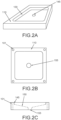
- the recessed section 140 may be in the form of a basin with a drain hole that extends all the way through the build plate 100 (e.g., from top surface 110 through bottom surface 120). This is depicted by FIGs. 2A-2C , which respectively show angled, top, and side views of build plate 100, including a recessed section 140 with a drain hole 145. As shown, the recessed section 140 is in the form of a basin that slopes downward toward hole 145 that extends out the bottom of build plate 100, thereby permitting a material (e.g., liquid metal) to be drained out of build plate 100.
- the dashed outlines depict the corner holes 101, drainage hole 155, and basin shapes. The bottom edges of the basin leading to the drainage hole are sloped in this example.
- the examples of the disclosure show the lower surface of recessed section 140 sloping down at an acute angle toward a centered, circular hole 145, other basin constructions, slope angles, hole locations, and hole shapes may be utilized.
- the recessed section may be implemented by perpendicularly sloping its sides into a flat bottom having a hole.
- the hole 145 may positioned off center (e.g., close to one of the corners of build plate 100).
- the hole 145 may instead drain through a side wall 130 of build plate 100.
- the hole 145 may be rectangular or square.
- the recessed section 140 may be formed via any suitable machining process such as by using a morticing machine, a metal lathe, a milling machine, a drill, etc.
- the recessed section 140 may be formed by morticing a solid block of metal.
- the top perimeter and average depth of recessed section 140 may be optimized for the 3D printing device and process used with build plate 100.
- the perimeter of the cutout may be shaped such that it does not interfere with a 3D printing device securing mechanism (e.g., providing sufficient space for holes 101) while providing a large enough surface area to form a 3D printed object.
- sufficient depth may be provided to optimize cooling and provide for a deeper channel.
- FIGs. 3A, 3B, and 3C respectively show angled, top, and bottom views of a build plate 100 filled by a solid material 160.
- the material filling recessed section 140 forms a flat surface flush to the top edges of the recessed section.
- the solid material 160 filling the recessed section 140 is visible through the drainage hole 155.
- the solid material 160 forms a flat surface flush at the top edges of the build plate basin, in other implementations it may lie below the top edges of the build plate basin.
- the solid material 160 is a solid metal or metal alloy having a melting point lower than that of the material (e.g., metal) of the unfilled build plate 100.
- the solidus temperature of the metal or metal alloy may be at least 30°C lower than that of the build plate 100.
- the differences in melting point may be more significant.
- the solidus temperature of the metal or metal alloy may be at least 50°C lower, 100°C lower, 200°C lower, 400°C lower, 600°C lower, 800°C lower, 1000°C lower, or even more than 1000°C lower than the solidus temperature of the build plate 100.
- the solid material 160 is a solid metal or metal alloy having a solidus temperature of less than 300°C. In some implementations, it has a solidus temperature between 50°C and 250°C.
- the solid material 160 may be a solder alloy such as tin alloys (e.g., 96.5Sn3Ag0.5Cu), bismuth alloys (e.g., 58Bi42Sn) or indium alloys (e.g., 52In48Sn).
- the solid material 160 may be a single elemental metal such as tin, bismuth, indium, or others.
- FIGs. 4A-4B depict one particular example of a method of forming solid material 160 in a recessed section 140 of build plate 100, in accordance with implementations of the disclosure.
- a flat plate or lid 700 covers the top surface of build plate 100, extending beyond the edges of recessed section 140 and the top surface 110 of build plate 100.
- lid 700 may extend up to or just beyond the edges of recessed section 140.
- Lid 700 may be held in place using clamps or other suitable mechanical means to create a seal.
- the material of lid 700 may be comprised of a material such that it does not bond with build plate 100 but may be mechanically held in place to create an enclosed mold.
- graphite, polytetrafluoroethylene, ceramic, cemented carbide, copper, stainless steel, tool steel, tin, aluminum, or some other suitable material may be used.
- the material of build plate 100 may be the same as or different from the material of lid 700.
- FIG. 4B illustrates a side view of the inverted build plate 100 and lid 700.
- a container 300 may be used to pour a liquid 165 of material (e.g., metal or metal alloy) through drainage hole 155 onto lid 700, filling the recessed section 140.
- the metal or metal alloy may be heated above its solidus temperature to form liquid 165.
- the use of a basin with acutely sloped sides may prevent the formation of air pockets when adding a liquid metal 165 through hole 155.
- any unwanted accumulates e.g., dross
- any unwanted accumulates may float to and settle at the top of the filled recessed section (i.e., where hole 155 is), thereby ensuring a clean metal or metal alloy surface is formed where 3D printing occurs.
- the assembly may be cooled, causing liquid 165 to solidify (e.g., to form a solid material 160). Thereafter, the lid 700 may be removed to expose a smooth, solid phase metal or metal alloy that provides a build surface for a 3D metal printed object.
- the lid 700 may be comprised of a material, e.g. graphite, polytetrafluoroethylene, ceramic, copper, stainless steel, tool steel, tin, aluminum, a non-stick metal, or some material that does not bond with liquid 165, before or after the liquid 165 solidifies.
- FIGs. 4A-4B depict one example technique for forming a solid material 160 in a recessed section 140 of a build plate 100 to provide a surface for a 3D printed object
- a liquid metal or metal alloy may instead be poured from the opposite side, through the top surface of recessed section 140, first filling drain 155.
- a lid 700 may instead cover drain 155.
- drain 155 may be on the side of build plate 155 (e.g., through a side wall 130), in which case the liquid metal or metal alloy may be poured through the side wall.
- the solid material 160 may be a pre-shaped solid insert that may be snapped or otherwise secured into or out of recessed section 140.
- the insert may be dimensioned such that it fits securely (e.g., occupies substantially all of the open volume) within the recessed section.
- multiple duplicate molds of the solid insert may be formed, with each mold being utilized during a 3D printing process.
- FIGs. 9A-9B illustrate inserts that may be used in accordance with implementations of the disclosure.
- FIG. 9A shows an insert 1000 that may be secured in a recess of a single piece build plate that has a rectangular recessed section.
- FIG. 9B shows an insert 1100 that may be secured in a two-piece build plate 200, further discussed below.
- a snap-in insert of solid material 160 obviates the requirement that an operator of the 3D printing system performs the labor-intensive process of casting the liquid metal 165 in advance, to form solid material 160 in the recessed section 140 of build plate 100. As such, additive manufacturing throughput may be significantly improved on the operator side by utilizing preformed, snap-in inserts. Additionally, the snap-in inserts may make operation of the 3D printing system more convenient and simpler for the operator When an operator completes 3D printing onto a solid material 160, as described herein, the operator may snap the insert of solid material 160 out, and subsequently melt the insert to retrieve the 3D printed object. For example, the insert may be snapped out by using a rod or other suitable tool to apply pressure to the insert via hole 155.
- a throughput advantage that may be realized from snapping out the insert with the 3D printed object is that the operator may quickly resume printing the next 3D metal printed object by snapping in a new insert 160.
- build plate 100 may not include hole 155, and some other suitable technique may be utilized to snap the insert out.
- the insert may be removed by melting it while it is still attached to build plate 100, and collecting the liquid metal via drain hole 155 as further described below with reference to FIG. 7 .
- an operator may be supplied a container in which to place an insert (with the 3D printed object) prior to melting
- the container may be sent back to the manufacturer of the solid insert (or some other party) to recycle the metal/metal alloy or reuse the metal/metal alloy to create a new insert (e.g., for the same user or a different user).
- FIG. 5 illustrates a 3D metal printing process including a 3D metal printing device 500 using a metal powder bed 550 and a laser 400 to form a 3D printed object 600 on a build plate 100, in accordance with implementations of the disclosure. Also shown is build plate loading platform 510 and optical component 410 for directing the output of a laser 400.
- the metal powder bed 550 may comprise aluminum, cobalt, copper, nickel, steel, stainless steel, titanium, vanadium, tungsten carbide, gold, bronze, platinum, silver alloys, cobalt-chromium alloys, refractory metals, a combination thereof, or some other suitable metal or metal alloy for forming 3D printed object 600.
- the 3D printed object may be laser sintered.
- a build plate 100 having a top surface including a region with a low melting temperature metal or metal alloy may be loaded into the 3D metal printing device 500.
- build plate 100 may be placed on a platform 510 of device 500.
- a first layer of metal powder may be deposited (e.g., using a doctor blade or wiper blade) over the top surface of build plate 100, including solid material 160.
- Laser 400 or a series of lasers may then lase/sinter the deposited metal powder, causing the first layer of 3D printed object 600 to be metallurgically joined to the solid material.
- additional layers of powdered metal may be deposited by metal powder bed 550 and 3D printed object 600 may be created layer by layer.
- the device 500 may include a lowering mechanism (e.g., as part of platform 510) apparatus to allow for subsequent metal layers of the 3D printed object 600 to be formed.
- a metal powder layer may be added to the top surface and a laser or laser(s) used to selectively join/sinter areas to the 3D printed object 600 below
- a laser or laser(s) used to selectively join/sinter areas to the 3D printed object 600 below
- build plate 100 with 3D printed object 600 may be removed from 3D printing device 500.
- the melting temperature of the metal or metal alloy that is used to form 3D printed object 600 is higher than that of the solid material 160.
- the solidus temperature of the 3D printed object 600 may be at least 30°C higher than the solidus temperature of the metal or metal alloy.
- the differences in melting point may be more significant.
- the solidus temperature of the 3D printed object 600 may be 50°C higher, 100°C higher, 200°C higher, 400°C higher, 600°C higher, 800°C higher, 1000°C higher, or even more than 1000°C higher than the solidus temperature of the metal or metal alloy of solid material 160.
- the metal powder used to form 3D printed object 600 may comprise aluminum, cobalt, copper, nickel, steel, stainless steel, titanium, vanadium, tungsten carbide, gold, bronze, platinum, silver alloys, cobalt-chromium alloys, refractory metals, a combination thereof, or some other suitable metal or metal alloy.
- the heat generated by laser 400 may increase the temperature of solid material 160. To prevent premature melting of material 160 during 3D printing, this increase in temperature may be accounted for when selecting a suitable metal or metal alloy 160.
- the power of laser 400 may be decreased while forming lower layers of 3D printed object 600 to prevent overheating of material 160 during 3D printing.
- FIG. 6 shows an assembly including the metal 3D printed object 600 metallurgically joined onto build plate 100 after the completion of 3D printing.
- the 3D printed object 600 may be joined to a surface of build plate 100 containing a low melting temperature solid material 160, as described above.
- the 3D printed object 600 is separated from build plate 100.
- the assembly may be heated (e.g., by placing the assembly in an oven) to a temperature above the solidus temperature of the low melting temperature solid material 160, thereby melting away the material and releasing the 3D printed object.
- the heat source is not limited to that of an oven.
- the 3D printed object 600 may be thermally separated from the solid material 160 by a heat source other than an oven such as by blow torch, heated air, heated liquid, hotplate, laser, or any other suitable heat source sufficient to melt the solid material 160, thereby releasing the 3D printed object 600.
- FIG. 7 shows a side view in which the low melting temperature metal or metal alloy filling the recessed section 140 of the build plate 100 is melting and draining (shown as melting liquid 166) through the drain hole 155 into container or collection apparatus 800 while the 3D printed object 600 and the remaining structure of build plate 100, including recessed section 140, remain solid.
- the 3D printed object 600 may be held in place by a tool. In some implementations, this process may be incorporated into a compartment of a 3D printing assembly
- a thin object such as a punch may be placed though drain hole 155 on the underside of build plate 100 with significant pressure to release the solid metal insert 160, with the 3D printed object 600 still attached, from the recessed section 140.
- the aforementioned combination may be placed into a container with a heated medium or subjected to other thermal treatment to cause the separation of solid metal insert 160 from 3D printed object 600.
- This separation method may be implemented on a preformed insert as described above, or on a solid material 160 formed via casting by the operator as described in FIGs. 4A-4B .
- the collected metal or metal alloy may be reused to refill the recessed section 140 for future 3D printing operations.
- the collected metal or metal alloy may be used to fill recessed section 140 as described above with reference to FIGs. 4A-4B , in preparation for printing a new 3D object.
- the solid material 160 may be a pre-shaped solid insert as discussed above, which can be snapped into or out of recessed section 140, eliminating the need to repour liquid metal into the mold for the next printing.
- FIG. 8 depicts the 3D printed object 600 after being separated from build plate 100 once the material filling recessed section 140 is no longer solid and melted away.
- the collected metal or metal alloy may be used to refixture the object 600 for polishing, reshaping, and/or grinding, as needed.
- 3D printing parts may be held using a clamping mechanism for post processing.
- the lower melting point material 160 may be used to secure the 3D printed object 600 into a vice or clamping mechanism while performing the post processing functions above, so that the clamp does not contact the part 600 directly.
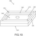
- FIG. 10 shows a perspective view of an alternate, multi-part build plate 200 that may be used for additive manufacturing or 3D printing, in accordance with implementations of the disclosure.
- build plate 200 includes a top surface 210, a bottom surface 220 and four sidewalls 230 that extend between the top and bottom surfaces.
- the build plate 200, including the top, bottom, and side surfaces, may be made of copper, stainless steel, tool steel, tin, aluminum, cemented carbide, ceramic, graphite, or some other suitable material.
- the multiple parts of the build plate 200 may be made of material (e.g., metal or metal alloy) having a solidus temperature that is substantially higher (e.g., at least 30°C) than that of a thermally decomposable material that is placed or formed in its recessed section 240, and used to create a bond between build plate 200 and a 3D printed object during 3D printing.
- the parts of build plate 200 may have a melting temperature that is greater than 1000°C.
- build plate 200 In contrast to the single-part design of build plate 100, build plate 200 includes multiple parts.
- FIG. 11-12 demonstrate an example of how build plate 200 may be implemented with multiple parts.
- build plate 200 includes base 280 and frame 270 configured to be attached over the base 280.
- the frame includes opening 241, and the base 280 includes recessed section 240.
- frame 270 is used to secure solid material 160 in place during the 3D printing process to keep it from lifting from recessed section 240 during 3D printing.
- the recessed section 240 is wider than the frame opening 241.
- frame 270 may provide a clamping force to secure a solid material 160.
- This two-part design may be particularly beneficial when implemented with an insert 1100 as discussed above.
- Frame 700 may be used to hold down insert 1100 along the outside edges of bottom portion 1110 of insert 1100, which may curl upwards during sintering if the insert becomes too hot.
- Frame 270 is removably coupled to base 280, and frame 270 may be removed from base 280 as to allow removal (or insertion) of the solid material.
- the bottom part 1110 of insert 1100 may be first secured into recessed section 240 of base 280.
- frame 270 may be secured over base 280, and the top part 1120 of insert 1100 may be secured in opening 241 of frame 270.
- Frame 270 and base 280 may be affixed through a number of means, including screws, set screws, pins, dovetail, sliding rails or other interlocking designs.
- FIGs. 13A-13B depict a particular example implementation for affixing an example frame 270a and a base 280a of an example build plate 200a.
- FIG. 13A shows a perspective view of build plate 200a.
- FIG. 13B shows a bottom view and cross-sectional views of build plate 200a.
- This example utilizes recessed holes 275 in frame 270a that may extend through holes in base 280a. Utilizing appropriately sized machine screws, frame 270a and base 280a may be secured via recessed holes 275.
- recessing the screw flush or below the top surface of build plate 200a i.e., below the top of frame 270
- Build plates consisting of multiple parts may employ various design features to ease separation of frame 270 from base 280.
- the build plate 200 may require separation to remove solid material 160 without melting the solid material 160.
- this example demonstrates an implementation that incorporates jack screw holes 285 in a base 280a to ease separation from a frame 270a. Bolts inserted into the jack screw holes 285 and tightened can be used to push the frame 270a away from the base 280a, or to push the base 280a away from the frame 270a.
- Several design features may also aid in disassembly, including tabs extending from the base 280 and/or the frame 270 or a nail nick or gap for prying apart the assembly
- the build plate 200 is composed of two parts - frame 270 and base 280, the build plate 200 may be made of more than two parts that are affixed using one or more of the aforementioned methods.
- means for attachment of build plate 200 to a 3D printing apparatus are represented by slots or holes 201 (e.g., bolt holes) in each corner of top surface 210.
- the bolt holes 201 may extend through frame 270 and base 280.
- Structural protrusions (e.g., bolts or tabs) of the 3D printing apparatus may be inserted into holes 201 to hold the build plate 200 in place during 3D printing.
- top surface 200 may include holes 201 and/or protrusions in any suitable location on top surface 210, bottom surface 220, and/or other surface of build plate 200 to facilitate attachment to the 3D printing apparatus
- holes 201 may be included on bottom surface 220 and not on top surface 210 to prevent powdered metal from 3D printing to fall into holes 201.
- build plate 200 includes a mortised or recessed section 240 extending through its center.
- the recessed section 240 is illustrated as having surfaces 245 (e.g., sidewalls) and a lower surface 250.
- the recessed section 240 may be filled with a lower melting temperature metal or metal alloy that provides a thermally decomposable surface for building a 3D printed object.
- the recessed section 240 may be in the form of a basin with a drain hole that extends all the way through the build plate 200 (e.g., from top surface 210 through bottom surface 220). This is depicted by FIGs. 11 and 12 , which show angled, top, and cross-sectional side views of build plate 200, including a recessed section 240 with a drain hole 245. As shown, the recessed section 240 is in the form of a basin that converges toward hole 245 that extends out the bottom of build plate 200, thereby permitting a material (e.g., liquid metal) to be drained out of build plate 200.
- the dashed outlines depict the corner holes 201, drainage hole 255, and basin shapes. The bottom edges of the basin leading to the drainage hole are flat in this example, although they can also be sloped to allow ease of drainage.
- the recessed section 240 may be formed via any suitable machining process such as by using a morticing machine, a metal lathe, a milling machine, a drill, etc.
- the recessed section 240 may be formed by morticing a solid block of metal.
- the top perimeter and average depth of recessed section 240 may be optimized for the 3D printing device and process used with build plate 200.
- the perimeter of the cutout may be shaped such that it does not interfere with a 3D printing device securing mechanism (e.g., providing sufficient space for holes 201) while providing a large enough surface area to form a 3D printed object.
- sufficient depth may be provided to optimize cooling and provide for a deeper channel.
- FIGs. 14A, 14B, and 14C respectively show angled, top, and bottom views of a build plate 200 filled by a solid material 160, in accordance with implementations of the disclosure.
- the material filling recessed section 240 forms a flat surface flush to the top edges of the recessed section.
- the solid material 160 filling the recessed section 240 is visible through the drainage hole 255.
- the solid material 160 forms a flat surface flush at the top edges of the build plate basin, in other implementations it may lie below the top edges of the build plate basin.
- the solid material 160 is a solid metal or metal alloy having a melting point lower than that of the material (e.g., metal) of the unfilled build plate 200.
- the solidus temperature of the metal or metal alloy may be at least 30°C lower than that of the build plate 200.
- the differences in melting point may be more significant.
- the solidus temperature of the metal or metal alloy may be at least 50°C lower, 100°C lower, 200°C lower, 400°C lower, 600°C lower, 800°C lower, 1000°C lower, or even more than 1000°C lower than the solidus temperature of the build plate 200.
- FIGs. 15-16 depict one particular example of a method of forming solid material 160 in a recessed section 240 of build plate 200, in accordance with implementations of the disclosure.
- a flat plate or lid 700 covers the top surface of build plate 200, extending beyond the edges of recessed section 240 and the top surface 210 of build plate 200.
- lid 700 may extend up to or just beyond the edges of recessed section 240.
- Lid 700 may be held in place using clamps or other suitable mechanical means to create a seal.
- the material of lid 700 may be comprised of a material such that it does not bond with build plate 200 but may be mechanically held in place to create an enclosed mold. For example, graphite, polytetrafluoroethylene, ceramic, cemented carbide, or some other suitable material may be used
- FIG. 16 illustrates a side view of the inverted build plate 200 and lid 700.
- a container 300 may be used to pour a liquid 165 of material (e.g., metal or metal alloy) through drainage hole 255 onto lid 700, filling the recessed section 240.
- the metal or metal alloy may be heated above its solidus temperature to form liquid 165.
- the use of a basin with acutely sloped sides may prevent the formation of air pockets when adding a liquid metal 165 through hole 255.
- any unwanted accumulates e.g., dross
- any unwanted accumulates may float to and settle at the top of the filled recessed section (i.e., where hole 255 is), thereby ensuring a clean metal or metal alloy surface is formed where 3D printing occurs.
- the assembly may be cooled, causing liquid 165 to solidify (e.g., to form a solid material 160). Thereafter, the lid 700 may be removed to expose a smooth, solid phase metal or metal alloy that provides a build surface for a 3D metal printed object.
- the lid 700 may be comprised of a material, e.g. graphite, polytetrafluoroethylene, ceramic, a non-stick metal, or some material that does not bond with liquid 165, before or after the liquid 165 solidifies.
- FIG. 17 illustrates a 3D metal printing process including a 3D metal printing device 500 using a metal powder bed 550 and a laser 400 to form a 3D printed object 600 on a build plate 200, in accordance with implementations of the disclosure. Also shown is build plate loading platform 510 and optical component 410 for directing the output of a laser 400.
- the metal powder bed 550 may comprise aluminum, cobalt, copper, nickel, steel, stainless steel, titanium, vanadium, tungsten carbide, gold, bronze, platinum, silver alloys, cobalt-chromium alloys, refractory metals, a combination thereof, or some other suitable metal or metal alloy for forming 3D printed object 600.
- the 3D printed object may be laser sintered.
- a build plate 200 having a top surface including a region with a low melting temperature metal or metal alloy may be loaded into the 3D metal printing device 500.
- build plate 200 may be placed on a platform 510 of device 500.
- a first layer of metal powder may be deposited (e.g., using a doctor blade or wiper blade) over the top surface of build plate 200, including solid material 160.
- Laser 400 or a series of lasers may then lase/sinter the deposited metal powder, causing the first layer of 3D printed object 600 to be metallurgically joined to the solid material.
- additional layers of powdered metal may be deposited by metal powder bed 550 and 3D printed object 600 may be created layer by layer.
- the device 500 may include a lowering mechanism (e.g., as part of platform 510) apparatus to allow for subsequent metal layers of the 3D printed object 600 to be formed.
- a metal powder layer may be added to the top surface and a laser or laser(s) used to selectively join/sinter areas to the 3D printed object 600 below
- a laser or laser(s) used to selectively join/sinter areas to the 3D printed object 600 below
- build plate 200 with 3D printed object 600 may be removed from 3D printing device 500.
- the melting temperature of the metal or metal alloy that is used to form 3D printed object 600 is higher than that of the solid material 160.
- the solidus temperature of the 3D printed object 600 may be at least 30°C higher than the solidus temperature of the metal or metal alloy.
- the differences in melting point may be more significant.
- the solidus temperature of the 3D printed object 600 may be 50°C higher, 100°C higher, 200°C higher, 400°C higher, 600°C higher, 800°C higher, 1000°C higher, or even more than 1000°C higher than the solidus temperature of the metal or metal alloy of solid material 160.
- the metal powder used to form 3D printed object 600 may comprise aluminum, cobalt, copper, nickel, steel, stainless steel, titanium, vanadium, tungsten carbide, gold, bronze, platinum, silver alloys, cobalt-chromium alloys, refractory metals, a combination thereof, or some other suitable metal or metal alloy
- the heat generated by laser 400 may increase the temperature of solid material 160. To prevent premature melting of material 160 during 3D printing, this increase in temperature may be accounted for when selecting a suitable metal or metal alloy 160.
- the power of laser 400 may be decreased while forming lower layers of 3D printed object 600 to prevent overheating of material 160 during 3D printing.
- FIG. 18 shows an assembly including the metal 3D printed object 600 metallurgically joined onto build plate 200 after the completion of 3D printing.
- the 3D printed object 600 may be joined to a surface of build plate 200 containing a low melting temperature solid material 160, as described above.
- the 3D printed object 600 is separated from build plate 200.
- the assembly may be heated (e.g., by placing the assembly in an oven) to a temperature above the solidus temperature of the low melting temperature solid material 160, thereby melting away the material and releasing the 3D printed object.
- FIG. 19 shows a side view in which the low melting temperature metal or metal alloy filling the recessed section 240 of the build plate 200 is melting and draining (shown as melting liquid 166) through the drain hole 255 into container or collection apparatus 800 while the 3D printed object 600 and the remaining structure of build plate 200, including recessed section 240, remain solid.
- the 3D printed object 600 may be held in place by a tool. In some implementations, this process may be incorporated into a compartment of a 3D printing assembly
- the collected metal or metal alloy may be reused to refill the recessed section 240 for future 3D printing operations.
- the collected metal or metal alloy may be used to fill recessed section 240 as described above with reference to FIGs. 15-16 , in preparation for printing a new 3D object.
- frame 210 may be separated from base 280, thereby exposing a top portion of solid material 160.
- a thin object such as a punch may be placed though drain hole 255 on the underside of build plate 200 with significant pressure to release the solid material 160, with the 3D printed object 600 still attached, from the recessed section 240.
- the aforementioned combination may be placed into a container with a heated medium or subjected to other thermal treatment to cause the separation of solid metal material 160 from 3D printed object 600.
- This separation method may be implemented on a preformed insert as described above, or on a solid material 160 formed via casting by the operator as described in FIGs. 15-16 .
- FIG. 20 depicts the 3D printed object 600 after being separated from build plate 200 once the material filling recessed section 240 is no longer solid and melted away.
- the collected metal or metal alloy may be used to refixture the object 600 for polishing, reshaping, and/or grinding, as needed.
- 3D printing parts may be held using a clamping mechanism for post processing.
- the lower melting point material 160 may be used to secure the 3D printed object 600 into a vice or clamping mechanism while performing the post processing functions above, so that the clamp does not contact the part 600 directly.
- a recessed section without a drain hole could be filled with a low melting temperature metal or metal alloy that provides a surface for 3D printing.
- the assembly may be heated to separate the 3D printed object from the metal or metal alloy, and the liquid metal or metal alloy may be removed using any suitable means, e.g., by inverting the assembly, using a suction tube, etc.
Landscapes
- Chemical & Material Sciences (AREA)
- Engineering & Computer Science (AREA)
- Materials Engineering (AREA)
- Manufacturing & Machinery (AREA)
- Physics & Mathematics (AREA)
- Mechanical Engineering (AREA)
- Optics & Photonics (AREA)
- Powder Metallurgy (AREA)
Claims (12)
- Bauplatte aus additiver Fertigung, umfassend:eine Oberseitenfläche, eine Unterseitenfläche und Seitenwände, die aus einem Material bestehen, wobei die Oberseitenfläche, die Unterseitenfläche und die Seitenwände derart bemessen sind, dass die Bauplatte in einer 3D-Druckvorrichtung verwendbar ist; undeinen ausgesparten Abschnitt, der durch die Oberseite gebildet ist, wobei der ausgesparte Abschnitt ein Loch umfasst, das sich durch die Unterseite der Bauplatte erstreckt; undein festes Metall oder eine feste Metalllegierung, das/die in dem ausgesparten Abschnitt angeordnet ist, um eine Fläche zum Bilden eines 3D-gedruckten Objekts in der 3D-Druckvorrichtung bereitzustellen, wobei das feste Metall oder die feste Metalllegierung eine Solidustemperatur aufweist, die niedriger als eine Solidustemperatur des Materials ist, das die Oberseitenfläche, die Unterseitenfläche und Seitenwände der Bauplatte bildet.
- Bauplatte aus additiver Fertigung nach Anspruch 1, wobei das feste Metall oder die feste Metalllegierung eine Solidustemperatur aufweist, die zudem niedriger als eine Solidustemperatur eines Druckmaterials ist, das zum Bilden des 3D-gedruckten Objekts verwendet wird.
- Bauplatte aus additiver Fertigung nach Anspruch 1, wobei das feste Metall oder die feste Metalllegierung ein Einschub eines festen Metalls oder einer festen Metalllegierung ist, wobei der Einschub bemessen ist, um in den ausgesparten Abschnitt eingefügt und darin gesichert zu werden.
- Bauplatte aus additiver Fertigung nach Anspruch 1, wobei das feste Metall oder die feste Metalllegierung ein festes Metall oder eine feste Metalllegierung ist, die in den ausgesparten Abschnitt gegossen wurde.
- Bauplatte aus additiver Fertigung nach Anspruch 1, wobei das feste Metall oder die feste Metalllegierung eine Solidustemperatur zwischen 50 °C und 250 °C aufweist.
- Bauplatte aus additiver Fertigung nach Anspruch 1, wobei das feste Metall oder die feste Metalllegierung eine flache Fläche bildet, die bündig an den Oberseitenkanten des ausgesparten Abschnitts der Bauplatte ist.
- Bauplatte aus additiver Fertigung nach Anspruch 1, wobei:(i) die Bauplatte aus additiver Fertigung Folgendes umfasst: ein einzelnes Teil, das die Oberseite, die Unterseite und die Seitenwände beinhaltet; oder(ii) wobei die Bauplatte aus additiver Fertigung Folgendes umfasst:einen Rahmen, der einen Innenausschnitt umfasst, der kleiner als der ausgesparte Abschnitt ist, wobei der Rahmen dazu konfiguriert ist, das Metall oder die Metalllegierung während eines 3D-Druckprozesses zu halten; undeine Basis, die den ausgesparten Abschnitt umfasst, wobei der Rahmen dazu konfiguriert ist, an der Oberseite der Basis befestigt zu werden.
- Bauplatte aus additiver Fertigung nach Anspruch 1, wobei der ausgesparte Abschnitt stark geneigte Seiten umfasst.
- Verfahren, umfassend:Erlangen einer Bauplatte, die in einer 3D-Druckvorrichtung verwendbar ist, wobei die Bauplatte Folgendes umfasst: eine Oberseitenfläche, eine Unterseitenfläche und Seitenwände, die aus einem Material bestehen; und einen ausgesparten Abschnitt, der durch die Oberseite gebildet ist, wobei der ausgesparte Abschnitt ein Loch umfasst, das sich durch die Unterseite der Bauplatte erstreckt;Wenden der Bauplatte, sodass die Unterseitenfläche nach oben gewandt ist;Abdecken der Oberseitenfläche der Bauplatte mit einem Deckel;Gießen durch Einfüllen einer flüssigen Form eines Metalls oder einer Metalllegierung durch das Loch in den ausgesparten Abschnitt; undKühlen des Metalls oder der Metalllegierung unter dessen/deren Solidustemperatur, um eine feste Form des Metalls oder der Metalllegierung zu bilden, wobei das Metall oder die Metalllegierung eine Solidustemperatur aufweist, die niedriger als eine Solidustemperatur des Materials ist, das die Oberseitenfläche, die Unterseitenfläche und die Seitenwände der Bauplatte bildet.
- Verfahren nach Anspruch 9, ferner umfassend: Drucken des 3D-gedruckten Objekts auf die Fläche der festen Form des Metalls oder der Metalllegierung, um eine Baugruppe zu bilden.
- Verfahren nach Anspruch 10, ferner umfassend: nach dem Drucken des 3D-gedruckten Objekts, Erwärmen der Baugruppe über die Solidustemperatur des Metalls oder der Metalllegierung, wodurch die feste Form des Metalls oder der Metalllegierung geschmolzen und das 3D-gedruckte Objekt von der Bauplatte freigegeben wird.
- Verfahren nach Anspruch 11, wobei das geschmolzene Metall oder die geschmolzene Metalllegierung durch das Loch abfließt, das sich durch das Loch in der Unterseitenfläche der Bauplatte erstreckt.
Applications Claiming Priority (2)
| Application Number | Priority Date | Filing Date | Title |
|---|---|---|---|
| US201962891143P | 2019-08-23 | 2019-08-23 | |
| PCT/US2020/047213 WO2021041154A1 (en) | 2019-08-23 | 2020-08-20 | Thermally decomposing build plate for facile release of 3d printed objects |
Publications (3)
| Publication Number | Publication Date |
|---|---|
| EP4017663A1 EP4017663A1 (de) | 2022-06-29 |
| EP4017663B1 true EP4017663B1 (de) | 2024-11-27 |
| EP4017663C0 EP4017663C0 (de) | 2024-11-27 |
Family
ID=72356508
Family Applications (1)
| Application Number | Title | Priority Date | Filing Date |
|---|---|---|---|
| EP20767660.2A Active EP4017663B1 (de) | 2019-08-23 | 2020-08-20 | Thermisch zersetzende bauplatte zur einfachen freigabe von 3d-druckobjekten |
Country Status (4)
| Country | Link |
|---|---|
| US (2) | US11766721B2 (de) |
| EP (1) | EP4017663B1 (de) |
| CN (1) | CN114555267B (de) |
| WO (1) | WO2021041154A1 (de) |
Families Citing this family (6)
| Publication number | Priority date | Publication date | Assignee | Title |
|---|---|---|---|---|
| WO2022182766A1 (en) | 2021-02-23 | 2022-09-01 | Indium Corporation | Thermally decomposing build plate with casting mold for facile release of 3d printed objects |
| TW202344372A (zh) * | 2022-03-24 | 2023-11-16 | 美商銦業公司 | 用於在3d列印期間金屬建造表面之穩定及經3d列印物件之簡易釋放之熱可分解建造板結構 |
| US12187656B2 (en) * | 2022-09-30 | 2025-01-07 | Raytheon Technologies Corporation | Ceramic matrix composite tooling for chemical vapor infiltration process |
| US11993548B2 (en) | 2022-09-30 | 2024-05-28 | Rtx Corporation | Minimization of chemical vapor infiltration tooling hole length through windows |
| SE2230446A1 (en) * | 2022-12-29 | 2024-06-30 | Seco Tools Ab | Detachable build plate |
| CN117464028A (zh) * | 2023-06-14 | 2024-01-30 | 宁夏东方智造科技有限公司 | 一种3d打印用基板及3d打印方法 |
Citations (1)
| Publication number | Priority date | Publication date | Assignee | Title |
|---|---|---|---|---|
| EP3424620A1 (de) * | 2017-07-06 | 2019-01-09 | General Electric Company | Dmlm-aufbau-trennschicht und verfahren zur verwendung davon |
Family Cites Families (62)
| Publication number | Priority date | Publication date | Assignee | Title |
|---|---|---|---|---|
| JP3133669B2 (ja) | 1996-02-09 | 2001-02-13 | 株式会社クボタ | 複合板材の製造方法 |
| US5980812A (en) * | 1997-04-30 | 1999-11-09 | Lawton; John A. | Solid imaging process using component homogenization |
| US6375880B1 (en) * | 1997-09-30 | 2002-04-23 | The Board Of Trustees Of The Leland Stanford Junior University | Mold shape deposition manufacturing |
| GB9927127D0 (en) * | 1999-11-16 | 2000-01-12 | Univ Warwick | A method of manufacturing an item and apparatus for manufacturing an item |
| US6547552B1 (en) * | 2000-02-08 | 2003-04-15 | Efrem V. Fudim | Fabrication of three-dimensional objects by irradiation of radiation-curable materials |
| EP1379287A1 (de) * | 2001-04-12 | 2004-01-14 | Therics, Inc. | Verfahren und vorrichtung für veränderte regenerative biostrukturen |
| JP4551087B2 (ja) * | 2001-10-03 | 2010-09-22 | スリーディー システムズ インコーポレーテッド | 相変化支持材料組成物 |
| WO2004106041A2 (en) * | 2003-05-23 | 2004-12-09 | Z Corporation | Apparatus and methods for 3d printing |
| US20050156361A1 (en) * | 2004-01-21 | 2005-07-21 | United Technologies Corporation | Methods for producing complex ceramic articles |
| US20070126157A1 (en) * | 2005-12-02 | 2007-06-07 | Z Corporation | Apparatus and methods for removing printed articles from a 3-D printer |
| CA2687432C (en) | 2008-01-28 | 2011-03-15 | Kabushiki Kaisha Saito Kanagata Seisakusho | In-mold degassing structure, and mold having the structure |
| JP5189953B2 (ja) * | 2008-10-22 | 2013-04-24 | パナソニック株式会社 | 三次元形状造形物の製造方法 |
| KR20100064195A (ko) | 2008-12-04 | 2010-06-14 | 이민호 | 맨홀뚜껑 및 그 주조방법 |
| US7991498B2 (en) * | 2009-02-03 | 2011-08-02 | Objet Geometries Ltd. | Method and system for building painted three-dimensional objects |
| ES2522115T5 (en) * | 2009-07-17 | 2025-07-31 | Cfp Composites Ltd | A fibre matrix and a method of making a fibre matrix |
| EP2359964B1 (de) | 2010-01-26 | 2013-11-20 | Alstom Technology Ltd | Verfahren zum Herstellen eines 3-dimensionalen Bauteils mittels selektiven Laserschmelzens (SLM) |
| DE102012106141B4 (de) * | 2012-07-09 | 2018-04-26 | Exone Gmbh | Verfahren und vorrichtung zum entpacken eines bauteils |
| US9327350B2 (en) * | 2012-08-16 | 2016-05-03 | Stratasys, Inc. | Additive manufacturing technique for printing three-dimensional parts with printed receiving surfaces |
| CN102921927B (zh) | 2012-11-15 | 2014-06-11 | 北京工业大学 | 双液双金属复合耐磨衬板制备方法 |
| EP2964411A4 (de) | 2013-03-05 | 2016-10-12 | United Technologies Corp | Plattformen zur herstellung von zusatzstoffen |
| JP6456353B2 (ja) * | 2013-03-12 | 2019-01-23 | オレンジ・メーカー・エルエルシー | 渦巻状の積上げを使用した3d印刷 |
| US9597730B2 (en) * | 2013-04-19 | 2017-03-21 | United Technologies Corporation | Build plate and apparatus for additive manufacturing |
| US9744730B2 (en) | 2013-11-22 | 2017-08-29 | Stratasys, Inc. | Magnetic platen assembly for additive manufacturing system |
| GB201322647D0 (en) * | 2013-12-20 | 2014-02-05 | Renishaw Plc | Additive manufacturing apparatus and method |
| EP3099470B1 (de) | 2014-01-29 | 2019-03-06 | Stocklyn Venture, LLC | Vorrichtung und verfahren zum entfernen eines 3d-druckmaterials von bauplatten von 3d-druckern |
| US10207325B2 (en) * | 2014-06-16 | 2019-02-19 | Delavan Inc. | Additive manufacture from machined surface |
| US20150367411A1 (en) | 2014-06-18 | 2015-12-24 | Gregory WITMYER | Methods for producing and cleaning sand castings |
| WO2015197305A1 (en) * | 2014-06-25 | 2015-12-30 | Comet Ag | Device for manufacturing of three-dimensional objects |
| US10537030B2 (en) * | 2014-08-25 | 2020-01-14 | Indium Corporation | Voiding control using solid solder preforms embedded in solder paste |
| CN104260353B (zh) * | 2014-09-24 | 2017-01-25 | 英华达(上海)科技有限公司 | 快速成型系统及其方法 |
| US11254068B2 (en) * | 2014-10-29 | 2022-02-22 | Hewlett-Packard Development Company, L.P. | Three-dimensional (3D) printing method |
| US10016852B2 (en) * | 2014-11-13 | 2018-07-10 | The Boeing Company | Apparatuses and methods for additive manufacturing |
| US9592660B2 (en) | 2014-12-17 | 2017-03-14 | Arevo Inc. | Heated build platform and system for three dimensional printing methods |
| FR3034116A1 (fr) * | 2015-03-27 | 2016-09-30 | Pierre-Emmanuel Drochon | Construction de batiments d'habitation au moyen de coffrages realises par impression 3d |
| US20170252818A1 (en) | 2016-03-03 | 2017-09-07 | Desktop Metal, Inc. | Dissolvable bulk metallic glass support materials |
| JP2019518864A (ja) | 2016-03-03 | 2019-07-04 | デスクトップ メタル インコーポレイテッドDesktop Metal, Inc. | 金属造形材料を用いた付加製造 |
| DE102016210542A1 (de) * | 2016-06-14 | 2017-12-14 | Testia Gmbh | 3D-Druckverfahren und 3D-Druckvorrichtung |
| US11155676B2 (en) * | 2016-06-20 | 2021-10-26 | Sabic Global Technologies B.V. | Polymer composition for selective sintering |
| US10377126B2 (en) * | 2016-07-19 | 2019-08-13 | General Electric Company | Retaining plates and disposable build plates for additive manufacturing systems |
| ES2945662T3 (es) * | 2016-08-12 | 2023-07-05 | Elc Man Llc | Dispositivo para la impresión de un artículo cosmético tridimensional a partir de un material de construcción que comprende una fórmula cosmética |
| NL2017474B1 (en) * | 2016-09-16 | 2018-03-22 | Additive Ind Bv | Apparatus for producing an object by means of additive manufacturing and method of using the apparatus |
| US10710302B2 (en) * | 2016-11-02 | 2020-07-14 | R3 Printing, Inc. | System and method for automated successive three-dimensional printing |
| US10286451B2 (en) * | 2016-11-02 | 2019-05-14 | General Electric Company | Build plate for additive manufacturing systems |
| US10493532B2 (en) * | 2017-01-17 | 2019-12-03 | General Electric Company | Thermal expansion fit build plate for additive manufacturing |
| US10717130B2 (en) * | 2017-02-22 | 2020-07-21 | General Electric Company | Method of manufacturing turbine airfoil and tip component thereof |
| CN107471651B (zh) * | 2017-03-03 | 2019-12-13 | 珠海赛纳打印科技股份有限公司 | 支撑结构、支撑结构的打印方法以及打印系统 |
| CN106891007A (zh) * | 2017-03-13 | 2017-06-27 | 江苏省海洋资源开发研究院(连云港) | 一种通孔结构金属多孔材料的3d打印制备工艺 |
| WO2018170375A1 (en) * | 2017-03-17 | 2018-09-20 | Desktop Metal, Inc. | Base plate in additive manufacturing |
| CN107116218A (zh) * | 2017-05-16 | 2017-09-01 | 山东大学 | 一种使用低熔点合金便于金属3d打印去除支撑的方法 |
| US10821519B2 (en) * | 2017-06-23 | 2020-11-03 | General Electric Company | Laser shock peening within an additive manufacturing process |
| WO2019017926A1 (en) * | 2017-07-19 | 2019-01-24 | Hewlett-Packard Development Company, L.P. | THREE DIMENSIONAL PRINTING (3D) |
| US10703044B2 (en) | 2017-07-27 | 2020-07-07 | Robert Bosch Tool Corporation | Removable build plate with evenly heated build surface of 3D printer |
| EP3461572A1 (de) | 2017-10-02 | 2019-04-03 | Siemens Aktiengesellschaft | Konstruktionsplatte zur generativen fertigung und verfahren |
| US20190152143A1 (en) * | 2017-11-17 | 2019-05-23 | General Electric Company | Powder reduction apparatus |
| CN207523030U (zh) * | 2017-11-22 | 2018-06-22 | 上海联泰科技股份有限公司 | 3d打印设备及其构建平台 |
| US10889054B2 (en) * | 2017-11-27 | 2021-01-12 | Hrl Laboratories, Llc | Sacrificial pyrolysis method for additively manufactured ceramics |
| KR102037348B1 (ko) * | 2017-12-19 | 2019-10-28 | 재단법인 포항산업과학연구원 | 3차원 프린팅용 빌드 플레이트 제거 장치 및 이를 이용한 제품 제조 방법 |
| CN108723549A (zh) * | 2018-05-28 | 2018-11-02 | 河海大学常州校区 | 一种电弧增材制造方法 |
| CN108748993A (zh) | 2018-05-30 | 2018-11-06 | 芜湖聚网信息技术有限公司 | 便捷式3d打印成型台 |
| US20190375014A1 (en) * | 2018-06-11 | 2019-12-12 | Desktop Metal, Inc. | Shrinking interface layers |
| CN110653345B (zh) | 2018-06-29 | 2024-05-31 | 丹佛斯(天津)有限公司 | 砂芯组件以及通过3d打印形成砂芯组件的方法 |
| WO2021262679A1 (en) | 2020-06-24 | 2021-12-30 | Vulcanforms Inc. | Plate mounting in additive manufacturing |
-
2020
- 2020-08-20 EP EP20767660.2A patent/EP4017663B1/de active Active
- 2020-08-20 WO PCT/US2020/047213 patent/WO2021041154A1/en not_active Ceased
- 2020-08-20 US US16/998,650 patent/US11766721B2/en active Active
- 2020-08-20 CN CN202080071231.5A patent/CN114555267B/zh active Active
-
2023
- 2023-08-23 US US18/454,606 patent/US20230405677A1/en active Pending
Patent Citations (1)
| Publication number | Priority date | Publication date | Assignee | Title |
|---|---|---|---|---|
| EP3424620A1 (de) * | 2017-07-06 | 2019-01-09 | General Electric Company | Dmlm-aufbau-trennschicht und verfahren zur verwendung davon |
Also Published As
| Publication number | Publication date |
|---|---|
| CN114555267A (zh) | 2022-05-27 |
| CN114555267B (zh) | 2024-06-28 |
| EP4017663A1 (de) | 2022-06-29 |
| US20230405677A1 (en) | 2023-12-21 |
| US20210053122A1 (en) | 2021-02-25 |
| WO2021041154A1 (en) | 2021-03-04 |
| EP4017663C0 (de) | 2024-11-27 |
| US11766721B2 (en) | 2023-09-26 |
Similar Documents
| Publication | Publication Date | Title |
|---|---|---|
| EP4017663B1 (de) | Thermisch zersetzende bauplatte zur einfachen freigabe von 3d-druckobjekten | |
| JP6389242B2 (ja) | 付加製造のためのビルドプレート及び装置 | |
| JP6904546B2 (ja) | ブレード先端部の製造方法とタービンブレードの先端部の修理方法 | |
| EP3278908B1 (de) | Stützstruktur, verfahren zur bereitstellung davon und verfahren zur additiven fertigung | |
| US10850355B2 (en) | Severing device | |
| JP3894574B2 (ja) | 切削工具を製造するための方法 | |
| US12042864B2 (en) | Thermally decomposing build plate with casting mold for facile release of 3D printed objects | |
| US11229955B2 (en) | Method for manufacturing a part of electroconductive material by additive manufacturing | |
| US20220266344A1 (en) | Build plate with thermally decomposing top surface for facile release of 3d printed objects | |
| CN106964860B (zh) | 在开口上进行焊接包覆的方法 | |
| RU2410226C2 (ru) | Способ изготовления полой лопатки, вершина которой имеет форму ванночки, а также способ ремонта такой лопатки | |
| US12023735B2 (en) | Thermally decomposable build plate structure for stabilization of metal build surface during 3D printing and facile release of 3D printed objects | |
| US20060218788A1 (en) | Method of manufacturing a hollow blade that includes a recessed tip cap and method of reparing such a blade | |
| US20240342802A1 (en) | Build plate with interchangeable insert to reduce lift-up during metal 3d printing | |
| JPH0691437A (ja) | 切削工具のドレッシング方法、研削工具のドレッシング方法、切削工具及び研削工具 | |
| CN115397650B (zh) | 用于在粉末床上对具有回转轴线的零件进行增材制造的模块化托盘 | |
| JP2571748B2 (ja) | ロータリーダイの製造方法 | |
| JP2006021281A (ja) | ワイヤ放電加工方法 | |
| WO2021020529A1 (ja) | ヒートシンク | |
| JPS58151979A (ja) | 圧延母材の先端溶加方法 | |
| HU194082B (en) | Method and apparatus for renewing casting dies | |
| JPH06155062A (ja) | レーザ加工装置 |
Legal Events
| Date | Code | Title | Description |
|---|---|---|---|
| STAA | Information on the status of an ep patent application or granted ep patent |
Free format text: STATUS: UNKNOWN |
|
| STAA | Information on the status of an ep patent application or granted ep patent |
Free format text: STATUS: THE INTERNATIONAL PUBLICATION HAS BEEN MADE |
|
| PUAI | Public reference made under article 153(3) epc to a published international application that has entered the european phase |
Free format text: ORIGINAL CODE: 0009012 |
|
| STAA | Information on the status of an ep patent application or granted ep patent |
Free format text: STATUS: REQUEST FOR EXAMINATION WAS MADE |
|
| 17P | Request for examination filed |
Effective date: 20220216 |
|
| AK | Designated contracting states |
Kind code of ref document: A1 Designated state(s): AL AT BE BG CH CY CZ DE DK EE ES FI FR GB GR HR HU IE IS IT LI LT LU LV MC MK MT NL NO PL PT RO RS SE SI SK SM TR |
|
| DAV | Request for validation of the european patent (deleted) | ||
| DAX | Request for extension of the european patent (deleted) | ||
| STAA | Information on the status of an ep patent application or granted ep patent |
Free format text: STATUS: EXAMINATION IS IN PROGRESS |
|
| 17Q | First examination report despatched |
Effective date: 20230110 |
|
| P01 | Opt-out of the competence of the unified patent court (upc) registered |
Effective date: 20230602 |
|
| REG | Reference to a national code |
Ref country code: DE Ref legal event code: R079 Free format text: PREVIOUS MAIN CLASS: B22F0003000000 Ipc: B22F0010000000 Ref country code: DE Ref legal event code: R079 Ref document number: 602020042095 Country of ref document: DE Free format text: PREVIOUS MAIN CLASS: B22F0003000000 Ipc: B22F0010000000 |
|
| GRAP | Despatch of communication of intention to grant a patent |
Free format text: ORIGINAL CODE: EPIDOSNIGR1 |
|
| STAA | Information on the status of an ep patent application or granted ep patent |
Free format text: STATUS: GRANT OF PATENT IS INTENDED |
|
| RIC1 | Information provided on ipc code assigned before grant |
Ipc: B22F 10/66 20210101ALN20240603BHEP Ipc: B22F 10/64 20210101ALN20240603BHEP Ipc: B22F 10/28 20210101ALN20240603BHEP Ipc: B33Y 30/00 20150101ALI20240603BHEP Ipc: B33Y 10/00 20150101ALI20240603BHEP Ipc: B29C 64/245 20170101ALI20240603BHEP Ipc: B22F 12/30 20210101ALI20240603BHEP Ipc: B22F 10/00 20210101AFI20240603BHEP |
|
| INTG | Intention to grant announced |
Effective date: 20240626 |
|
| GRAS | Grant fee paid |
Free format text: ORIGINAL CODE: EPIDOSNIGR3 |
|
| GRAA | (expected) grant |
Free format text: ORIGINAL CODE: 0009210 |
|
| STAA | Information on the status of an ep patent application or granted ep patent |
Free format text: STATUS: THE PATENT HAS BEEN GRANTED |
|
| AK | Designated contracting states |
Kind code of ref document: B1 Designated state(s): AL AT BE BG CH CY CZ DE DK EE ES FI FR GB GR HR HU IE IS IT LI LT LU LV MC MK MT NL NO PL PT RO RS SE SI SK SM TR |
|
| REG | Reference to a national code |
Ref country code: GB Ref legal event code: FG4D |
|
| REG | Reference to a national code |
Ref country code: CH Ref legal event code: EP |
|
| REG | Reference to a national code |
Ref country code: IE Ref legal event code: FG4D |
|
| REG | Reference to a national code |
Ref country code: DE Ref legal event code: R096 Ref document number: 602020042095 Country of ref document: DE |
|
| U01 | Request for unitary effect filed |
Effective date: 20241127 |
|
| U07 | Unitary effect registered |
Designated state(s): AT BE BG DE DK EE FI FR IT LT LU LV MT NL PT RO SE SI Effective date: 20241203 |
|
| P04 | Withdrawal of opt-out of the competence of the unified patent court (upc) registered |
Free format text: CASE NUMBER: APP_63457/2024 Effective date: 20241129 |
|
| PG25 | Lapsed in a contracting state [announced via postgrant information from national office to epo] |
Ref country code: IS Free format text: LAPSE BECAUSE OF FAILURE TO SUBMIT A TRANSLATION OF THE DESCRIPTION OR TO PAY THE FEE WITHIN THE PRESCRIBED TIME-LIMIT Effective date: 20250327 Ref country code: HR Free format text: LAPSE BECAUSE OF FAILURE TO SUBMIT A TRANSLATION OF THE DESCRIPTION OR TO PAY THE FEE WITHIN THE PRESCRIBED TIME-LIMIT Effective date: 20241127 |
|
| PG25 | Lapsed in a contracting state [announced via postgrant information from national office to epo] |
Ref country code: ES Free format text: LAPSE BECAUSE OF FAILURE TO SUBMIT A TRANSLATION OF THE DESCRIPTION OR TO PAY THE FEE WITHIN THE PRESCRIBED TIME-LIMIT Effective date: 20241127 |
|
| PG25 | Lapsed in a contracting state [announced via postgrant information from national office to epo] |
Ref country code: NO Free format text: LAPSE BECAUSE OF FAILURE TO SUBMIT A TRANSLATION OF THE DESCRIPTION OR TO PAY THE FEE WITHIN THE PRESCRIBED TIME-LIMIT Effective date: 20250227 |
|
| PG25 | Lapsed in a contracting state [announced via postgrant information from national office to epo] |
Ref country code: GR Free format text: LAPSE BECAUSE OF FAILURE TO SUBMIT A TRANSLATION OF THE DESCRIPTION OR TO PAY THE FEE WITHIN THE PRESCRIBED TIME-LIMIT Effective date: 20250228 |
|
| PG25 | Lapsed in a contracting state [announced via postgrant information from national office to epo] |
Ref country code: PL Free format text: LAPSE BECAUSE OF FAILURE TO SUBMIT A TRANSLATION OF THE DESCRIPTION OR TO PAY THE FEE WITHIN THE PRESCRIBED TIME-LIMIT Effective date: 20241127 |
|
| PG25 | Lapsed in a contracting state [announced via postgrant information from national office to epo] |
Ref country code: RS Free format text: LAPSE BECAUSE OF FAILURE TO SUBMIT A TRANSLATION OF THE DESCRIPTION OR TO PAY THE FEE WITHIN THE PRESCRIBED TIME-LIMIT Effective date: 20250227 |
|
| PG25 | Lapsed in a contracting state [announced via postgrant information from national office to epo] |
Ref country code: SM Free format text: LAPSE BECAUSE OF FAILURE TO SUBMIT A TRANSLATION OF THE DESCRIPTION OR TO PAY THE FEE WITHIN THE PRESCRIBED TIME-LIMIT Effective date: 20241127 |
|
| PG25 | Lapsed in a contracting state [announced via postgrant information from national office to epo] |
Ref country code: SK Free format text: LAPSE BECAUSE OF FAILURE TO SUBMIT A TRANSLATION OF THE DESCRIPTION OR TO PAY THE FEE WITHIN THE PRESCRIBED TIME-LIMIT Effective date: 20241127 |
|
| PG25 | Lapsed in a contracting state [announced via postgrant information from national office to epo] |
Ref country code: CZ Free format text: LAPSE BECAUSE OF FAILURE TO SUBMIT A TRANSLATION OF THE DESCRIPTION OR TO PAY THE FEE WITHIN THE PRESCRIBED TIME-LIMIT Effective date: 20241127 |
|
| U20 | Renewal fee for the european patent with unitary effect paid |
Year of fee payment: 6 Effective date: 20250709 |
|
| PLBE | No opposition filed within time limit |
Free format text: ORIGINAL CODE: 0009261 |
|
| STAA | Information on the status of an ep patent application or granted ep patent |
Free format text: STATUS: NO OPPOSITION FILED WITHIN TIME LIMIT |
|
| PGFP | Annual fee paid to national office [announced via postgrant information from national office to epo] |
Ref country code: GB Payment date: 20250703 Year of fee payment: 6 |
|
| 26N | No opposition filed |
Effective date: 20250828 |