EP4017170B1 - Hilfsinformationsberichtverfahren und konfigurationsverfahren, endgerät und netzseitige vorrichtung - Google Patents
Hilfsinformationsberichtverfahren und konfigurationsverfahren, endgerät und netzseitige vorrichtung Download PDFInfo
- Publication number
- EP4017170B1 EP4017170B1 EP20851649.2A EP20851649A EP4017170B1 EP 4017170 B1 EP4017170 B1 EP 4017170B1 EP 20851649 A EP20851649 A EP 20851649A EP 4017170 B1 EP4017170 B1 EP 4017170B1
- Authority
- EP
- European Patent Office
- Prior art keywords
- terminal
- assistance information
- reporting
- target cell
- srb
- Prior art date
- Legal status (The legal status is an assumption and is not a legal conclusion. Google has not performed a legal analysis and makes no representation as to the accuracy of the status listed.)
- Active
Links
Images


Classifications
-
- H—ELECTRICITY
- H04—ELECTRIC COMMUNICATION TECHNIQUE
- H04W—WIRELESS COMMUNICATION NETWORKS
- H04W72/00—Local resource management
- H04W72/20—Control channels or signalling for resource management
- H04W72/21—Control channels or signalling for resource management in the uplink direction of a wireless link, i.e. towards the network
-
- H—ELECTRICITY
- H04—ELECTRIC COMMUNICATION TECHNIQUE
- H04W—WIRELESS COMMUNICATION NETWORKS
- H04W76/00—Connection management
- H04W76/20—Manipulation of established connections
- H04W76/25—Maintenance of established connections
-
- H—ELECTRICITY
- H04—ELECTRIC COMMUNICATION TECHNIQUE
- H04W—WIRELESS COMMUNICATION NETWORKS
- H04W36/00—Hand-off or reselection arrangements
- H04W36/0005—Control or signalling for completing the hand-off
- H04W36/0055—Transmission or use of information for re-establishing the radio link
- H04W36/0058—Transmission of hand-off measurement information, e.g. measurement reports
-
- H—ELECTRICITY
- H04—ELECTRIC COMMUNICATION TECHNIQUE
- H04W—WIRELESS COMMUNICATION NETWORKS
- H04W36/00—Hand-off or reselection arrangements
- H04W36/0005—Control or signalling for completing the hand-off
- H04W36/0055—Transmission or use of information for re-establishing the radio link
- H04W36/0072—Transmission or use of information for re-establishing the radio link of resource information of target access point
- H04W36/00725—Random access channel [RACH]-less handover
-
- H—ELECTRICITY
- H04—ELECTRIC COMMUNICATION TECHNIQUE
- H04W—WIRELESS COMMUNICATION NETWORKS
- H04W72/00—Local resource management
- H04W72/20—Control channels or signalling for resource management
- H04W72/23—Control channels or signalling for resource management in the downlink direction of a wireless link, i.e. towards a terminal
-
- H—ELECTRICITY
- H04—ELECTRIC COMMUNICATION TECHNIQUE
- H04W—WIRELESS COMMUNICATION NETWORKS
- H04W74/00—Wireless channel access
- H04W74/002—Transmission of channel access control information
- H04W74/004—Transmission of channel access control information in the uplink, i.e. towards network
-
- H—ELECTRICITY
- H04—ELECTRIC COMMUNICATION TECHNIQUE
- H04W—WIRELESS COMMUNICATION NETWORKS
- H04W76/00—Connection management
- H04W76/10—Connection setup
- H04W76/15—Setup of multiple wireless link connections
-
- H—ELECTRICITY
- H04—ELECTRIC COMMUNICATION TECHNIQUE
- H04W—WIRELESS COMMUNICATION NETWORKS
- H04W76/00—Connection management
- H04W76/10—Connection setup
- H04W76/18—Management of setup rejection or failure
-
- H—ELECTRICITY
- H04—ELECTRIC COMMUNICATION TECHNIQUE
- H04W—WIRELESS COMMUNICATION NETWORKS
- H04W36/00—Hand-off or reselection arrangements
- H04W36/0005—Control or signalling for completing the hand-off
- H04W36/0055—Transmission or use of information for re-establishing the radio link
- H04W36/0069—Transmission or use of information for re-establishing the radio link in case of dual connectivity, e.g. decoupled uplink/downlink
-
- H—ELECTRICITY
- H04—ELECTRIC COMMUNICATION TECHNIQUE
- H04W—WIRELESS COMMUNICATION NETWORKS
- H04W76/00—Connection management
- H04W76/10—Connection setup
- H04W76/19—Connection re-establishment
Definitions
- the present disclosure relates to the field of communication technologies, and in particular, to a method for reporting assistance information, a method for configuring reporting of assistance information, a terminal, and a network side device.
- a terminal supporting dual connectivity can simultaneously establish connections to two cells or two cell groups.
- the terminal may maintain connections to a source cell and a target cell simultaneously. Then the terminal may release the connection to the source cell, but only maintain the connection to the target cell.
- DC dual connectivity
- Document US20180124648A1 discloses a method including: receiving, by a first base station from a second base station, a request message for a handover of a wireless device, wherein the request message comprises traffic pattern parameters for one or more SPS traffic of the wireless device; determining, by the first base station, based at least on the traffic pattern parameters, at least one SPS configuration parameter for SPS radio resources; sending, by the first base station to the second base station, a handover request acknowledge message indicating the at least one SPS configuration parameter; receiving, by the first base station from the wireless device, a random access (RA) preamble associated with the handover of the wireless device; determining a subframe in a plurality of subframes based at least on the traffic pattern parameters; and transmitting, by the first base station to the wireless device, an SPS activation control command in the subframe indicating activation of the SPS radio resources.
- RA random access
- Embodiments of the present disclosure provides a method for reporting assistance information, a method for configuring reporting of assistance information, a terminal, and a network side device according to the appended set of claims, to resolve the problem that how a terminal reports assistance information in a dual connectivity application scenario.
- words such as “exemplarily” or “for example” represent being used as examples, illustrations, or illustrations. Any embodiment or design solution described as “exemplarily” or “for example” in the embodiments of the present disclosure shall not be construed as being more preferable or advantageous than other embodiments or design solutions. To be precise, words such as “exemplarily” or “for example” are used to present related concepts in a specific manner.
- a dual connectivity application scenario of a terminal is briefly described before the technical solutions of the embodiments of the present disclosure are described in detail.
- the terminal may simultaneously establish connections to two cell groups. That is, the terminal may simultaneously establish connections to a master cell group (MCG) and a secondary cell group (SCG).
- MCG master cell group
- SCG secondary cell group
- the MCG includes a primary cell (PCell) and a secondary cell (SCell)
- the SCG includes a primary secondary cell (PSCell) and a SCell.
- the PCell and the PSCell may alternatively be referred to as a special cell (SpCell).
- a dual connectivity mobility process for example, a dual connectivity handover or a SCG change, exists.
- the terminal maintains connections to a source cell and a target cell simultaneously (step 4 in FIG. 1 ), and then the terminal releases the connection to the source cell, and only maintains the connection to the target cell (step 5 in FIG. 1 ).
- the terminal may need to report assistance information to a network side.
- the terminal reports the assistance information only when there is assistance information to be reported for the first time or when contents of the previously reported assistance information changes.
- the terminal reports assistance information only when there is assistance information to be reported for the first time or when contents of the previously reported assistance information changes.
- the network side device configures the terminal to be allowed to report assistance information to a source cell and a target cell, and in a dual connectivity mobility process, if the terminal reports assistance information in the source cell, and contents of the assistance information does not change, the terminal will not report the contents of the assistance information again.
- the target cell cannot obtain the assistance information of the terminal, which further affects the communication performance in the dual connectivity application scenario.
- the embodiments of the present disclosure provide a method for reporting assistance information, a method for configuring reporting of assistance information, a terminal, and a network side device.
- the wireless communication system may be a 5G system, an evolved long term evolution (eLTE) system, or a subsequent evolution communication system.
- eLTE evolved long term evolution
- FIG. 2 is a structural diagram of a network system according to an embodiment of the present disclosure.
- FIG. 2 includes a terminal 21, a network side device 22 of a source cell, and a network side device 23 of a target cell.
- the terminal 21 may be a mobile communication device, for example, a mobile phone, a tablet personal computer, a laptop computer, a personal digital assistant (PDA), a mobile Internet device (MID), or a wearable device. It should be noted that a specific type of the terminal 21 is not limited in the embodiments of the present disclosure.
- the network side device 22 of the source cell and the network side device 23 of the target cell may be 5G network side devices (such as gNBs and 5GNRNBs), 4G network side devices (for example, eNBs), 3G network side devices (for example, NBs), network side devices in a subsequent evolution communication system, or the like. It should be noted that a specific type of the network side device 22 of the source cell and the network side device 23 of the target cell is not limited in the embodiments of the present disclosure.
- FIG. 3 is a flowchart of a method for reporting assistance information according to an embodiment of the present disclosure, where the method is applicable to the network system shown in FIG. 2 .
- the method includes the following steps: Step 301: A network side device of a source cell or a network side device of a target cell sends control information to a terminal.
- the network side device configures, by using the control information, the terminal to report assistance information to the target cell in a dual connectivity mobility process.
- the terminal maintains connections to the source cell and the target cell simultaneously.
- the network side device includes at least one of a network side device of the source cell or a network side device of the target cell.
- Step 302 The terminal receives the control information sent by the network side device.
- Step 303 The terminal reports assistance information of the terminal to the target cell in a dual connectivity mobility process.
- Step 304 The network side device of the target cell receives the assistance information of the terminal.
- the terminal reports assistance information of the terminal to the target cell may be understood as that: the terminal reports the assistance information of the terminal to the network side device of the target cell.
- the terminal reports the assistance information of the terminal to the source cell it may be understood as that: the terminal reports the assistance information of the terminal to the network side device of the source cell.
- a network side device sends control information to a terminal, where the control information is used for configuring the terminal to report assistance information to a target cell in a dual connectivity mobility process.
- the terminal can report assistance information to the target cell in the dual connectivity mobility process, which ensures the advantage that the target cell obtains the assistance information in the dual connectivity mobility process, thereby avoiding a case in which reporting of assistance information to a source cell by the terminal causes the target cell to be incapable of obtaining the assistance information in the dual connectivity mobility process.
- This method helps to keep contents of the assistance information consistent between the network side device and the terminal, and helps to improve the communication performance in the dual connectivity application scenario.
- FIG. 4 is a flowchart of a method for reporting assistance information according to an embodiment of the present disclosure. As shown in FIG. 4 , the method for reporting assistance information is applied to a terminal, and the method includes the following steps: Step 401: Report assistance information of the terminal to a target cell in a dual connectivity mobility process.
- the terminal maintains connections to a source cell and the target cell simultaneously.
- the dual connectivity mobility process includes a dual connectivity handover or a SCG change.
- the terminal may release the connection to the source cell, and only maintains the connection to the target cell.
- the source cell may be a cell group including a plurality of cells, that is, a source cell group; and the target cell may also be a cell group including a plurality of cells, that is, a target cell group.
- An ending condition of the dual connectivity mobility process may include any one of the following:
- the terminal only maintains the connection to the target cell, and the assistance information of the terminal may alternatively be reported to the target cell after the dual connectivity mobility process.
- the assistance information of the terminal may include at least one of the following:
- the terminal After the terminal reports some of the foregoing assistance information, for example, the overheat indication assistance information, the terminal starts an inhibition timer corresponding to the assistance information, and during running of the inhibition timer, the terminal cannot report the assistance information again.
- the terminal After the terminal reports some of the foregoing assistance information, for example, the overheat indication assistance information, the terminal starts an inhibition timer corresponding to the assistance information, and during running of the inhibition timer, the terminal cannot report the assistance information again.
- the terminal may report the assistance information of the terminal to the target cell by using a signaling radio bearer 1 (SRB 1) of the target cell.
- SRB 1 is used for sending a radio resource control (RRC) message of a dedicated control channel (DCCH) logic channel, for example, a connection reconfiguration message.
- RRC radio resource control
- DCCH dedicated control channel
- NAS non-access stratum
- a terminal reports assistance information to a target cell in a dual connectivity mobility process, which ensures the advantage that the target cell obtains the assistance information in the dual connectivity mobility process, thereby avoiding a case in which reporting of assistance information to a source cell by the terminal causes the target cell to be incapable of obtaining the assistance information in the dual connectivity mobility process.
- This method helps to keep contents of the assistance information consistent between the network side device and the terminal, and helps to improve the communication performance in the dual connectivity application scenario.
- the method further includes:
- the terminal in addition to reporting the assistance information of the terminal to the target cell, the terminal is prohibited from reporting the assistance information of the terminal to the source cell.
- the terminal there are three manners of reporting assistance information by the terminal as follows: first, the terminal reports the assistance information of the terminal to the target cell; second, the terminal reports the assistance information of the terminal to the target cell, and the terminal is prohibited from reporting the assistance information of the terminal to the source cell; third, the terminal reports the assistance information of the terminal to the target cell, and the terminal reports the assistance information of the terminal to the source cell.
- the terminal reports the assistance information of the terminal to the target cell, and is prohibited from reporting the assistance information of the terminal to the source cell.
- the network side device may instruct the terminal to report assistance information in the source cell and the target cell.
- the network side device may send control information, for example, dual connectivity mobility process control information, to the terminal, to instruct the terminal to be allowed to report assistance information in the source cell and the target cell, for example, instruct the terminal to be allowed to report assistance information in the source cell and the target cell simultaneously.
- the terminal may trigger a dual connectivity mobility process, for example, a dual connectivity handover, according to the dual connectivity mobility process control information.
- the terminal is configured to be allowed to report assistance information in the source cell and the target cell, it is predefined by a protocol that in a dual connectivity mobility process, the terminal is prohibited from reporting assistance information to the source cell. For example, when the terminal triggers assistance information to the source cell, it is considered that an inhibition timer corresponding to the assistance information to the source cell is running, so that the terminal does not report the assistance information to the source cell.
- the terminal complies with the protocol, and in the dual connectivity mobility process, the terminal is prohibited from reporting the assistance information of the terminal to the source cell, and only reports the assistance information of the terminal to the target cell.
- the method further includes: reporting the assistance information of the terminal to the source cell if the connection of the terminal to the target cell fails and the terminal maintains the connection to the source cell.
- the terminal can be agreed in a protocol that when the connection to the target cell fails, if the connection of the terminal to the source cell can still wok normally and the terminal has assistance information to report, the terminal is allowed to report the assistance information to the source cell.
- contents of the assistance information can also be kept consistent between the network side device and the terminal, thereby helping to improve the communication performance in the dual connectivity application scenario.
- a network side device instructs the terminal to disable reporting of assistance information in the source cell, and to report assistance information in the target cell
- the terminal reports the assistance information of the terminal to the target cell, and is prohibited from reporting the assistance information of the terminal to the source cell.
- the network side device may send control information, for example, dual connectivity mobility process control information, to the terminal, to instruct the terminal to disable reporting of assistance information in the source cell, and to instruct the terminal report assistance information in the target cell.
- control information for example, dual connectivity mobility process control information
- the network side device may disable reporting of assistance information to the source cell or not configure reporting of assistance information to the source cell in otherConfig of source cell (or source cell group) configuration information in the dual connectivity mobility process control information.
- the terminal may trigger a dual connectivity mobility process, for example, a dual connectivity handover, according to the dual connectivity mobility process control information.
- the network side device may be a network side device of the source cell and a network side device of the target cell. That is, the network side device may include at least one of the network side device of the source cell and the network side device of the target cell.
- a dual connectivity mobility process preparation message sent by the network side device of the source cell (which may alternatively be referred to as a source node) to a network side device of the target cell (which may alternatively be referred to as a target node) instructs to disable reporting of assistance information to the source cell.
- the network side device of the source cell disables reporting of assistance information to the source cell in configuration information of the source cell.
- a dual connectivity mobility process confirmation message sent by the network side device of the target cell to a network side device of the source cell instructs to disable reporting of assistance information to the source cell.
- the network side device of the target cell instructs to disable reporting of assistance information to the source cell.
- the terminal does not report the assistance information of the terminal to the source cell, and only reports the assistance information of the terminal to the target cell.
- the method further includes: reporting the assistance information of the terminal to the source cell if the connection of the terminal to the target cell fails and the terminal maintains the connection to the source cell.
- the terminal can be agreed in a protocol that when the connection to the target cell fails, if the connection of the terminal to the source cell can still wok normally and the terminal has assistance information to report, the terminal is allowed to report the assistance information to the source cell.
- contents of the assistance information can also be kept consistent between the network side device and the terminal, thereby helping to improve the communication performance in the dual connectivity application scenario.
- the method before the reporting assistance information of the terminal to a target cell, the method further includes:
- the network side device may send control information, for example, dual connectivity mobility process control information, to the terminal.
- control information for example, dual connectivity mobility process control information
- the network side device may send corresponding RRC message sending channel configuration information to the terminal.
- the RRC message sending channel configuration information may include configuration information of an SRB1 and an SRB2 used in the target cell (or target cell group).
- the RRC message sending channel configuration information may further include configuration information used for instructing to delete an SRB 1 and an SRB2 of the source cell (or source cell group). Further, if the source cell (or source cell group) includes an SRB3 previously, the RRC message sending channel configuration information may further include configuration information used for instructing to delete the SRB3 of the source cell (or source cell group). Further, for a case that a plurality of accessed target cells each include an MCG and an SCG, the RRC message sending channel configuration information may further include configuration information used for instructing to configure an SRB3 to the SCG.
- the SRB 1 is used for sending an RRC message of a DCCH logic channel, for example, a connection reconfiguration message.
- the SRB1 may alternatively be used for sending a NAS message before the SRB2 is established.
- the terminal may report the assistance information of the terminal to the network side device by using the SRB 1.
- the SRB2 is used for sending a NAS message by using a DCCH logic channel.
- the SRB2 has a lower priority than the SRB 1 and may be configured after the security of an access network is activated.
- the terminal may report the assistance information of the terminal to the network side device by using the SRB2.
- the SRB3 is used for sending an RRC message of the SCG by using a DCCH logic channel.
- the first SRB of the source cell may be understood as at least one of the SRB 1, the SRB2, or the SRB3 of the source cell
- the second SRB of the target cell may be understood as at least one of the SRB1, the SRB2, or the SRB3 of the target cell.
- the RRC message sending channel configuration information sent by the network side device includes configuration information of the SRB 1 and the SRB2 used in the target cell, and further includes configuration information used for instructing to delete the SRB1 and the SRB2 of the source cell.
- the terminal may trigger a dual connectivity mobility process according to configuration information of the network side device. For the source cell (or source cell group), the terminal deletes the SRB 1 and the SRB2 of the source cell (or the source cell group). For the target cell (or target cell group), the terminal establishes an SRB1 and an SRB2. If the source cell (or source cell group) includes an SRB3 previously, the terminal may alternatively delete the SRB3 of the source cell (or source cell group). In addition, for a case that a plurality of accessed target cells each include an MCG and an SCG, if the network side device configures an SRB3 to the SCG, the terminal may establish an SRB3 for the SCG.
- the terminal may send and receive corresponding RRC messages in the target cell (or target cell group) according to respective functions of the SRB 1, the SRB2, or the SRB3, for example, send the assistance information of the terminal.
- the terminal For the source cell (or source cell group), because the source cell includes no SRB1, SRB2, or SRB3, the terminal cannot report the assistance information of the terminal to the source cell (or source cell group).
- related configuration of the RRC message sending channel configuration information may also be agreed in a protocol.
- the terminal deletes the first SRB of the source cell and establishes the second SRB of the target cell, so that the terminal cannot report the assistance information of the terminal to the source cell, and only reports the assistance information of the terminal to the target cell.
- the method further includes: establishing a third SRB of the source cell, where the third SRB is used for reporting information indicating that the connection of the terminal to the target cell fails and/or the third SRB is not used for reporting the assistance information of the terminal.
- the network side device may send control information, for example, dual connectivity mobility process control information, to the terminal.
- the network side device may send corresponding RRC message sending channel configuration information to the terminal.
- the RRC message sending channel configuration information may include SRBx (for example, SRB4) configuration information used in the source cell (or source cell group), where the "SRBx configuration information" includes a logic channel identifier (for example, a logic channel identifier 4) corresponding to the SRBx.
- the SRBx of the source cell (or source cell group) can send include information used for indicating that the connection of the terminal to the target cell fails (which is referred to as "target cell connection failure information" for short).
- target cell connection failure information information used for indicating that the connection of the terminal to the target cell fails.
- the terminal reports the target cell connection failure information to the network side device by using the SRBx of the source cell.
- the terminal may further be agreed in a protocol that the types of messages that the SRBx of the source cell (or source cell group) can send do not include the assistance information of the terminal. In other words, the terminal cannot send the assistance information of the terminal to the source cell by using the SRBx of the source cell.
- a third SRB of the source cell may be understood as the SRBx of the source cell.
- the target cell connection failure information may include at least one of the following:
- the method further includes: reporting the information indicating that the connection of the terminal to the target cell fails to the source cell by using the third SRB.
- the method before the reporting assistance information of the terminal to a target cell, the method further includes:
- the network side device may send control information, for example, dual connectivity mobility process control information, to the terminal.
- the network side device may send corresponding RRC message sending channel configuration information to the terminal.
- the RRC message sending channel configuration information may include configuration information of an SRB1 and an SRB2 used in the target cell (or target cell group). Further, for a case that a plurality of accessed target cells each include an MCG and an SCG, the RRC message sending channel configuration information may further include configuration information used for instructing to configure an SRB3 to the SCG.
- the RRC message sending channel configuration information may further include configuration information used for modifying the types of messages that the SRB1 of the source cell (or source cell group) can send.
- the types of messages that the SRB1 of the source cell (or source cell group) can send include the assistance information of the terminal, and in the dual connectivity mobility process, the types of messages that the SRB1 of the source cell (or source cell group) can send do not include the assistance information of the terminal.
- the types of messages that the SRB 1 of the source cell (or source cell group) can send may include information used for indicating that the connection of the terminal to the target cell fails (which is referred to as "target cell connection failure information" for short). For example, the connection of the terminal to the target cell fails, and the terminal reports the target cell connection failure information to the network side device by using the SRB1 of the source cell.
- a fourth SRB of the source cell may be understood as the SRB 1 of the source cell, and a fifth SRB of the target cell may be understood as at least one of the SRB1, the SRB2, or the SRB3 of the target cell.
- the RRC message sending channel configuration information sent by the network side device includes configuration information of the SRB 1 and the SRB2 used in the target cell, and further includes configuration information used for modifying the types of messages that the SRB1 of the source cell (or source cell group) can send.
- the terminal may trigger a dual connectivity mobility process according to configuration information of the network side device. For the source cell (or source cell group), the terminal maintains the SRB 1 of the source cell (or the source cell group). For the target cell (or target cell group), the terminal establishes an SRB1 and an SRB2. In addition, for a case that a plurality of accessed target cells each include an MCG and an SCG, if the network side device configures an SRB3 to the SCG, the terminal may establish an SRB3 for the SCG.
- the terminal may send and receive corresponding RRC messages in the target cell (or target cell group) according to respective functions of the SRB 1, the SRB2, or the SRB3, for example, send the assistance information of the terminal.
- the terminal For the source cell (or source cell group), because the SRB 1 of the source cell (or source cell group) cannot be used for reporting the assistance information of the terminal in the dual connectivity mobility process, the terminal cannot report the assistance information of the terminal to the source cell (or source cell group).
- related configuration of the RRC message sending channel configuration information may also be agreed in a protocol.
- the terminal maintains the fourth SRB of the source cell, because the fourth SRB of the source cell is not used for reporting the assistance information of the terminal in the dual connectivity mobility process, the terminal cannot report the assistance information of the terminal to the source cell.
- the terminal establishes the fifth SRB of the target cell, so that the terminal only reports the assistance information of the terminal to the target cell.
- the method further includes: reporting the information indicating that the connection of the terminal to the target cell fails to the source cell by using the fourth SRB.
- a network side device instructs the terminal to report assistance information in the source cell and the target cell
- the terminal reports the assistance information of the terminal to the target cell and the source cell.
- the network side device may send control information, for example, dual connectivity mobility process control information, to the terminal, to instruct the terminal to be allowed to report assistance information in the source cell and the target cell, for example, instruct the terminal to be allowed to report assistance information in the source cell and the target cell simultaneously.
- control information for example, dual connectivity mobility process control information
- the terminal may trigger a dual connectivity mobility process, for example, a dual connectivity handover, according to the dual connectivity mobility process control information.
- the terminal may report the assistance information of the terminal to the target cell, and may also report the assistance information of the terminal to the source cell.
- the terminal may report the assistance information of the terminal to the target cell and the source cell in the following two manners: First manner: The assistance information of the terminal is duplicated to generate first assistance information and second assistance information, the first assistance information is sent to the source cell, and the second assistance information is sent to the target cell. Second manner: Third assistance information is generated according to configuration information of the source cell, the third assistance information is sent to the source cell, fourth assistance information is generated according to configuration information of the target cell, and the fourth assistance information is sent to the target cell.
- the terminal For reporting of assistance information triggered by each triggering condition, the terminal generates two pieces of assistance information. That is, the terminal duplicates the assistance information to generate the first assistance information and the second assistance information, and performs reporting through the source cell and the target cell respectively. For example, contents of MBMS interest information of the terminal changes, and an RRC layer of the terminal triggers to report the MBMS interest information to the network side device, then the RRC layer of the terminal generates two MBMS interest messages, where one MBMS interest message is sent by the SRB1 connected to the source cell, and the other MBMS interest message is sent by the SRB1 connected to the target cell. In this manner, the first assistance information and the second assistance information may be same assistance information.
- the RRC layer of the terminal triggers reporting of RRC assistance information twice.
- the third assistance information is generated according to the configuration information of the source cell and reported to the source cell; and during the other triggering operation, the fourth assistance information is generated according to the configuration information of the target cell and reported to the target cell, where both the configuration information are configuration information used for triggering the terminal to report the assistance information, for example, SIB 15.
- contents of MBMS interest information of the terminal changes, and an RRC layer of the terminal triggers to report the MBMS interest information to the network side device, then the terminal triggers to generate an MBMS interest message according to SIB15 of the source cell and sends the MBMS interest message by using the SRB 1 connected to the source cell, and the terminal triggers to generate another MBMS interest message according to SIB15 of the target cell and sends the MBMS interest message by using the SRB1 connected to the target cell.
- the third assistance information and the fourth assistance information may be different assistance information.
- a report time point of the third assistance information differs from a report time point of the fourth assistance information by a preset time.
- the terminal triggers to generate the third assistance information according to the configuration information of the source cell and reports the third assistance information to the source cell, and after the preset time, the terminal triggers to generate the fourth assistance information according to the configuration information of the target cell and reports the fourth assistance information to the target cell.
- the terminal triggers to generate the third assistance information according to the configuration information of the source cell and reports the third assistance information to the source cell.
- the terminal triggers reporting of assistance information in the source cell. After triggering or sending assistance information of the source cell, and after one second, the terminal triggers reporting of assistance information in the target cell.
- the preset time may be configured by the network side device or agreed by a protocol.
- a terminal reports assistance information to a target cell in a dual connectivity mobility process, which ensures the advantage that the target cell obtains the assistance information in the dual connectivity mobility process, thereby avoiding a case in which reporting of assistance information to a source cell by the terminal causes the target cell to be incapable of obtaining the assistance information in the dual connectivity mobility process.
- This method helps to keep contents of the assistance information consistent between the network side device and the terminal, and helps to improve the communication performance in the dual connectivity application scenario.
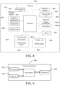
- FIG. 5 is a flowchart of a method for configuring reporting of assistance information according to an embodiment of the present disclosure.
- the method for configuring reporting of assistance information is applied to a network side device and the method includes the following steps: Step 501: Send control information to a terminal, where the control information is used for the terminal to report assistance information to a target cell in a dual connectivity mobility process.
- the terminal maintains connections to a source cell and the target cell simultaneously; and the network side device includes at least one of a network side device of the source cell or a network side device of the target cell.
- control information is further used for:
- the method before the sending control information to a terminal, the method further includes:
- control information includes RRC message sending channel configuration information, where the RRC message sending channel configuration information is used for indicating configuration information of a first SRB used in the target cell, where the first SRB is used for reporting the assistance information of the terminal.
- the RRC message sending channel configuration information is further used for indicating configuration information used for instructing to delete a second SRB of the source cell, where the second SRB is used for reporting the assistance information of the terminal.
- the RRC message sending channel configuration information is further used for indicating configuration information of a third SRB used in the source cell, where the third SRB is used for reporting information indicating that the connection of the terminal to the target cell fails and/or the third SRB is not used for reporting the assistance information of the terminal.
- the RRC message sending channel configuration information is further used for indicating a fourth SRB used in the source cell, where before the dual connectivity mobility process, the fourth SRB is used for reporting the assistance information of the terminal, and in the dual connectivity mobility process, the fourth SRB is used for reporting information indicating that the connection of the terminal to the target cell fails and/or the fourth SRB is not used for reporting the assistance information of the terminal.
- a network side device sends control information to a terminal, where the control information is used for configuring the terminal to report assistance information to a target cell in a dual connectivity mobility process.
- the terminal can report assistance information to the target cell in the dual connectivity mobility process, which ensures the advantage that the target cell obtains the assistance information in the dual connectivity mobility process, thereby avoiding a case in which reporting of assistance information to a source cell by the terminal causes the target cell to be incapable of obtaining the assistance information in the dual connectivity mobility process.
- This method helps to keep contents of the assistance information consistent between the network side device and the terminal, and helps to improve the communication performance in the dual connectivity application scenario.
- this embodiment of the present disclosure is used as an embodiment of the network side device corresponding to the embodiment shown in FIG. 4 , and for a specific implementation thereof, reference may be made to related descriptions of the embodiment shown in FIG. 4 , and the same beneficial effects can be achieved, which will not be described in detail herein again to avoid repetition.
- FIG. 6 is a structural diagram of a terminal according to an embodiment of the present disclosure. As shown in FIG. 6 , a terminal 600 includes:
- the sending module 601 is further configured to:
- the sending module 601 is configured to report the assistance information of the terminal to the target cell, and is prohibited from reporting the assistance information of the terminal to the source cell; or if a network side device instructs the terminal to disable reporting of assistance information in the source cell, and to report assistance information in the target cell, the sending module 601 is configured to report the assistance information of the terminal to the target cell, and is prohibited from reporting the assistance information of the terminal to the source cell.
- the sending module 601 is further configured to: report the assistance information of the terminal to the source cell if the connection of the terminal to the target cell fails and the terminal maintains the connection to the source cell.
- the network side device includes at least one of a network side device of the source cell or a network side device of the target cell.
- the terminal 600 further includes:
- the terminal 600 further includes: a second establishment module, configured to establish a third SRB of the source cell, where the third SRB is used for reporting information indicating that the connection of the terminal to the target cell fails and/or the third SRB is not used for reporting the assistance information of the terminal.
- a second establishment module configured to establish a third SRB of the source cell, where the third SRB is used for reporting information indicating that the connection of the terminal to the target cell fails and/or the third SRB is not used for reporting the assistance information of the terminal.
- the sending module 601 is further configured to: report the information indicating that the connection of the terminal to the target cell fails to the source cell by using the third SRB.
- the terminal 600 further includes:
- the sending module 601 is configured to report the assistance information of the terminal to the target cell and the source cell.
- the sending module 601 is specifically configured to:
- a report time point of the third assistance information differs from a report time point of the fourth assistance information by a preset time, where the preset time is configured by a network side or agreed by a protocol.
- the terminal 600 in this embodiment of the present disclosure may be the terminal in any implementation of the method embodiments. Any implementation of the terminal in the method embodiments may be implemented by the terminal 600 in this embodiment of the present disclosure, and the same beneficial effects can be achieved, which will not be described in detail herein again to avoid repetition.
- FIG. 7 is a structural diagram of a network side device according to an embodiment of the present disclosure.
- the network side device 700 includes: a sending module 701, configured to send control information to a terminal, where the control information is used for configuring the terminal to report assistance information to a target cell in a dual connectivity mobility process;
- the terminal maintains connections to a source cell and the target cell simultaneously; and the network side device includes at least one of a network side device of the source cell or a network side device of the target cell.
- control information is further used for:
- the sending module 701 is further configured to:
- control information includes RRC message sending channel configuration information, where the RRC message sending channel configuration information is used for indicating configuration information of a first SRB used in the target cell, where the first SRB is used for reporting the assistance information of the terminal.
- the RRC message sending channel configuration information is further used for indicating configuration information used for instructing to delete a second SRB of the source cell, where the second SRB is used for reporting the assistance information of the terminal.
- the RRC message sending channel configuration information is further used for indicating configuration information of a third SRB used in the source cell, where the third SRB is used for reporting information indicating that the connection of the terminal to the target cell fails and/or the third SRB is not used for reporting the assistance information of the terminal.
- the RRC message sending channel configuration information is further used for indicating a fourth SRB used in the source cell, where before the dual connectivity mobility process, the fourth SRB is used for reporting the assistance information of the terminal, and in the dual connectivity mobility process, the fourth SRB is used for reporting information indicating that the connection of the terminal to the target cell fails and/or the fourth SRB is not used for reporting the assistance information of the terminal.
- the network side device 700 in this embodiment of the present disclosure may be the network side device in any implementation of the method embodiments. Any implementation of the network side device in the method embodiments may be implemented by the network side device 700 in this embodiment of the present disclosure, and the same beneficial effects can be achieved, which will not be described in detail herein again to avoid repetition.
- FIG. 8 is a schematic structural diagram of hardware of a terminal configured to implement the embodiments of the present disclosure.
- the terminal 800 includes, but is not limited to, components such as a radio frequency (RF) unit 801, a network module 802, an audio output unit 803, an input unit 804, a sensor 805, a display unit 806, a user input unit 807, an interface unit 808, a memory 809, a processor 810, and a power source 811.
- RF radio frequency
- the terminal in the embodiments of the present disclosure includes, but is not limited to, a mobile phone, a tablet computer, a notebook computer, a palmtop computer, a vehicle-mounted terminal, a wearable device, a pedometer, and the like.
- the RF unit 801 is configured to:
- the RF unit 801 is further configured to:
- the RF unit 801 is configured to report the assistance information of the terminal to the target cell, and is prohibited from reporting the assistance information of the terminal to the source cell; or if a network side device instructs the terminal to disable reporting of assistance information in the source cell, and to report assistance information in the target cell, the RF unit 801 is configured to report the assistance information of the terminal to the target cell, and is prohibited from reporting the assistance information of the terminal to the source cell.
- the RF unit 801 is further configured to: report the assistance information of the terminal to the source cell if the connection of the terminal to the target cell fails and the terminal maintains the connection to the source cell.
- the network side device includes at least one of a network side device of the source cell or a network side device of the target cell.
- the RF unit 801 or the processor 810 is configured to:
- the RF unit 801 or the processor 810 is configured to: establish a third SRB of the source cell, where the third SRB is used for reporting information indicating that the connection of the terminal to the target cell fails and/or the third SRB is not used for reporting the assistance information of the terminal.
- the RF unit 801 is further configured to: report the information indicating that the connection of the terminal to the target cell fails to the source cell by using the third SRB.
- the RF unit 801 or the processor 810 is configured to:
- the RF unit 801 is configured to report the assistance information of the terminal to the target cell and the source cell.
- the RF unit 801 or the processor 810 is specifically configured to:
- the RF unit 801 or the processor 810 is specifically configured to: generate third assistance information according to configuration information of the source cell and report the third assistance information to the source cell, and generate fourth assistance information according to configuration information of the target cell and report the fourth assistance information to the target cell.
- a report time point of the third assistance information differs from a report time point of the fourth assistance information by a preset time, where the preset time is configured by a network side or agreed by a protocol.
- a terminal reports assistance information to a target cell in a dual connectivity mobility process, which ensures the advantage that the target cell obtains the assistance information in the dual connectivity mobility process, thereby avoiding a case in which reporting of assistance information to a source cell by the terminal causes the target cell to be incapable of obtaining the assistance information in the dual connectivity mobility process.
- This method helps to keep contents of the assistance information consistent between the network side device and the terminal, and helps to improve the communication performance in the dual connectivity application scenario.
- the RF unit 801 is configured to receive and send signals during an information receiving and sending process or a call process.
- the RF unit 801 is configured to receive downlink data from a base station, send the downlink data to the processor 810 for processing, and send uplink data to the base station.
- the RF unit 801 includes, but is not limited to, an antenna, at least one amplifier, a transceiver, a coupler, a low noise amplifier, a duplexer, and the like.
- the RF unit 801 may further communicate with other devices through a wireless communications system/network.
- the terminal provides wireless broadband Internet access for a user by using the network module 802, for example, allowing the user to receive and send emails, browse webpages, access streaming media content, and so on.
- the audio output unit 803 may convert audio data received by the RF unit 801 or the network module 802 or stored in the memory 809 into an audio signal and output the audio signal as a sound.
- the audio output unit 803 may provide an audio output (such as a call signal receiving sound or a message receiving sound) related to a specific function executed by the terminal 800.
- the audio output unit 803 includes a loudspeaker, a buzzer, a receiver, and the like.
- the input unit 804 is configured to receive an audio or video signal.
- the input unit 804 may include a graphics processing unit (GPU) 8041 and a microphone 8042.
- the GPU 8041 is configured to process image data of a static picture or a video that is captured by an image capturing apparatus (for example, a camera) in a video capture mode or an image capture mode.
- An image frame that has been processed may be displayed on the display unit 806.
- the image frame that has been processed by the GPU 8041 may be stored in the memory 809 (or other storage media) or sent by using the RF unit 801 or the network module 802.
- the microphone 8042 may receive a sound, and can process the sound into audio data.
- the processed audio data may be converted, in a phone call mode, into a format that can be sent to a mobile communication base station through the RF unit 801 for output.
- the terminal 800 may further include at least one sensor 805, such as an optical sensor, a motion sensor, and other sensors.
- the optical sensor includes an ambient light sensor and a proximity sensor.
- the ambient light sensor may adjust luminance of a display panel 8061 according to the luminance of ambient light
- the proximity sensor may switch off the display panel 8061 and backlight when the terminal 800 is moved to an ear.
- an acceleration sensor may detect magnitude of accelerations in various directions (generally on three axes), and detect the magnitude and direction of gravity at rest.
- the acceleration sensor is configured to recognize the attitude of the terminal (for example, switching between landscape orientation and portrait orientation, related gaming, and magnetometer attitude calibration), a function related to vibration recognition (such as a pedometer and a knock), and the like.
- the sensor 805 may further include a fingerprint sensor, a pressure sensor, an iris sensor, a molecular sensor, a gyroscope, a barometer, a hygrometer, a thermometer, an infrared sensor, and the like, which will not be described in detail herein.
- the display unit 806 is configured to display information inputted by the user or information to be presented to the user.
- the display unit 806 may include a display panel 8061.
- the display panel 8061 may be configured in the form of a liquid crystal display (LCD), an organic light-emitting diode (OLED), or the like.
- the user input unit 807 is configured to receive inputted digital or character information, and generate a key signal input related to user settings and function control of the terminal.
- the user input unit 807 may include a touch panel 8071 and other input devices 8072.
- the touch panel 8071 also called a touch screen, is configured to collect a touch operation made by the user on or in proximity to the touch panel 8071 (e.g., an operation made by the user through any appropriate object or attachment (e.g., finger or stylus) on or in proximity to the touch panel 8071).
- the touch panel 8071 may include a touch detection apparatus and a touch controller.
- the touch detection apparatus is configured to detect a touch position of the user and a signal generated due to the touch operation, and transmit the signal to the touch controller.
- the touch controller is configured to receive touch information from the touch detection apparatus, convert the touch information into coordinates of a touch point, transmit the coordinates to the processor 810, and receive and execute a command sent from the processor 810.
- the touch panel 8071 may be of a resistive type, a capacitive type, an infrared type, or a surface acoustic wave (SAW) type.
- the user input unit 807 may further include the other input devices 8072.
- the other input devices 8072 include, but not limited to, a physical keyboard, a functional button (such as a volume control button or an on/off button), a trackball, a mouse, and a joystick, which will not be described in detail herein.
- the touch panel 8071 may cover the display panel 8071.
- the touch panel 8071 transmits the touch information to the processor 810 so as to determine a type of a touch event. Then, the processor 810 provides a corresponding visual output on the display panel 8061 in accordance with the type of the touch event.
- the touch panel 8071 and the display panel 8061 are used as two separate parts to implement input and output functions of the terminal in FIG. 8 , in some embodiments, the touch panel 8071 and the display panel 8061 may be integrated to implement the input and output functions of the terminal, which is not limited herein.
- the interface unit 808 is an interface configured to connect an external apparatus to the terminal 800.
- the external apparatus may include a wired or wireless headset port, an external power source (or battery charger) port, a wired or wireless data port, a storage card port, a port configured to connect an apparatus having an identification module, an audio input/output (I/O) port, a video I/O port, an earphone port, and the like.
- the interface unit 808 is configured to receive an input (such as data information or electric power) from the external apparatus and transmit the received input to one or more elements in the terminal 800 or is configured to transmit data between the terminal 800 and the external apparatus.
- the memory 809 is configured to store a software program and various data.
- the memory 809 may mainly include a program storage region and a data storage region.
- the program storage region may store an operating system, an application (e.g., a sound play function or an image play function) required by at least one function, and the like.
- the data storage region may store data (e.g., audio data or a phonebook) that is created during use of the mobile phone, and the like.
- the memory 809 may include a high speed RAM, and may further include a non-volatile memory, such as at least one magnetic disk storage device, a flash memory, or another volatile solid storage device.
- the processor 810 is the control center of the terminal, and is connected to various parts of the terminal by various interfaces and lines. By running or executing the software program and module stored in the memory 809 and invoking data stored in the memory 809, the processor 810 performs various functions of the terminal and processes data, thereby monitoring the terminal.
- the processor 810 may include one or more processing units.
- the processor 810 may integrate an application processor and a modem processor.
- the application processor mainly handles operating systems, user interfaces, applications, and the like.
- the modem processor mainly handles wireless communication. It may be understood that the modem processor may not be integrated into the processor 810.
- the terminal 800 further includes the power source 811 (such as a battery) configured to supply power to the components.
- the power source 811 may be logically connected to the processor 810 by a power management system, so as to implement functions such as charging, discharging, and power consumption management via the power management system.
- the terminal 800 includes some functional modules not shown, which will not be described in detail herein.
- the embodiments of the present disclosure further provide a terminal, including a processor 810, a memory 809, and a computer program stored in the memory 809 and executable by the processor 810.
- the computer program when executed by the processor 810, implements the processes of the embodiments of the foregoing method for reporting assistance information, and the same technical effects can be achieved, which will not be described in detail herein again to avoid repetition.
- the terminal 800 in this embodiment may be the terminal in any implementation of the method embodiments in the embodiments of the present disclosure. Any implementation of the terminal in the method embodiments in the embodiments of the present disclosure may be implemented by the terminal 800 in this embodiment, and the same beneficial effects can be achieved, which will not be described in detail herein again.
- FIG. 9 is a structural diagram of a network side device according to an embodiment of the present disclosure.
- the network side device 900 includes: a processor 901, a transceiver 902, a memory 903, and a bus interface.
- the transceiver 902 is configured to:
- control information is further used for:
- the transceiver 902 is further configured to:
- control information includes RRC message sending channel configuration information, where the RRC message sending channel configuration information is used for indicating configuration information of a first SRB used in the target cell, where the first SRB is used for reporting the assistance information of the terminal.
- the RRC message sending channel configuration information is further used for indicating configuration information used for instructing to delete a second SRB of the source cell, where the second SRB is used for reporting the assistance information of the terminal.
- the RRC message sending channel configuration information is further used for indicating configuration information of a third SRB used in the source cell, where the third SRB is used for reporting information indicating that the connection of the terminal to the target cell fails and/or the third SRB is not used for reporting the assistance information of the terminal.
- the RRC message sending channel configuration information is further used for indicating a fourth SRB used in the source cell, where before the dual connectivity mobility process, the fourth SRB is used for reporting the assistance information of the terminal, and in the dual connectivity mobility process, the fourth SRB is used for reporting information indicating that the connection of the terminal to the target cell fails and/or the fourth SRB is not used for reporting the assistance information of the terminal.
- a network side device sends control information to a terminal, where the control information is used for configuring the terminal to report assistance information to a target cell in a dual connectivity mobility process.
- the terminal can report assistance information to the target cell in the dual connectivity mobility process, which ensures the advantage that the target cell obtains the assistance information in the dual connectivity mobility process, thereby avoiding a case in which reporting of assistance information to a source cell by the terminal causes the target cell to be incapable of obtaining the assistance information in the dual connectivity mobility process.
- This method helps to keep contents of the assistance information consistent between the network side device and the terminal, and helps to improve the communication performance in the dual connectivity application scenario.
- the bus architecture may include any quantity of interconnected buses and bridges, which is specifically connected by one or more processors represented by a processor 901 and various circuits of memories represented by a memory 903.
- the bus architecture may further connect various other circuits such as a peripheral device, a voltage stabilizer, and a power management circuit. These are known in the art, and therefore are not further described in this specification.
- the bus interface provides an interface.
- the transceiver 902 may be a plurality of elements, that is, including a transmitter and a receiver, providing a unit configured to communicate with various other apparatuses on a transmission medium.
- the user interface 904 may alternatively be an interface capable of connecting externally and internally with a required device.
- the connected device includes, but not limited to, a keypad, a display, a speaker, a microphone, a joystick, and the like.
- the processor 901 is responsible for the management of the bus architecture and normal processing, and the memory 903 may store data used when the processor 901 performs an operation.
- the network side device 900 in this embodiment may be the network side device in any implementation of the method embodiments in the embodiments of the present disclosure. Any implementation of the network side device in the method embodiments in the embodiments of the present disclosure may be implemented by the network side device 900 in this embodiment, and the same beneficial effects can be achieved, which will not be described in detail herein again.
- the embodiments of the present disclosure further provide a computer-readable storage medium, storing a computer program.
- the computer program when executed by a processor, implements the processes of the embodiments corresponding to the terminal or the network side device, and the same technical effects can be achieved, which will not be described in detail herein again to avoid repetition.
- the computer-readable storage medium is, for example, a read-only memory (ROM), a random access memory (RAM), a magnetic disk, or an optical disc.
- the computer software product is stored in a storage medium (for example, a ROM/ RAM, a magnetic disk, or an optical disc), and contains several instructions for instructing a terminal (which may be a mobile phone, a computer, a server, an air conditioner, or a network device) to perform the method according to the embodiments of the present disclosure.
- a storage medium for example, a ROM/ RAM, a magnetic disk, or an optical disc
- a terminal which may be a mobile phone, a computer, a server, an air conditioner, or a network device
Landscapes
- Engineering & Computer Science (AREA)
- Computer Networks & Wireless Communication (AREA)
- Signal Processing (AREA)
- Mobile Radio Communication Systems (AREA)
Claims (15)
- Verfahren zum Melden von Unterstützungsinformationen, das von einem Endgerät durchgeführt wird, dadurch gekennzeichnet, dass das Verfahren Folgendes umfasst:Melden (401) von Unterstützungsinformationen des Endgeräts an eine Zielzelle in einem Dual-Connectivity-Mobilitätsprozess,wobei das Endgerät in dem Dual-Connectivity-Mobilitätsprozess gleichzeitig Verbindungen zu einer Quellzelle und zu der Zielzelle aufrechterhält,wobei das Verfahren in dem Dual-Connectivity-Mobilitätsprozess ferner Folgendes umfasst:
wobei es dem Endgerät untersagt ist, Unterstützungsinformationen des Endgeräts an die Quellzelle zu melden. - Verfahren nach Anspruch 1, wobei, wenn es durch ein Protokoll vordefiniert ist, dass es dem Endgerät untersagt ist, Unterstützungsinformationen an die Quellzelle in dem Dual-Connectivity-Mobilitätsprozess zu melden, das Endgerät die Unterstützungsinformationen des Endgeräts an die Zielzelle meldet und ihm untersagt ist, die Unterstützungsinformationen des Endgeräts an die Quellzelle zu melden; oder
wenn eine netzwerkseitige Vorrichtung das Endgerät anweist, die Meldung von Unterstützungsinformationen in der Quellzelle zu deaktivieren und die Unterstützungsinformationen in der Zielzelle zu melden, das Endgerät die Unterstützungsinformationen des Endgeräts an die Zielzelle meldet und ihm untersagt ist, die Unterstützungsinformationen des Endgeräts an die Quellzelle zu melden. - Verfahren nach Anspruch 2, zudem umfassend:
Melden der Unterstützungsinformationen des Endgeräts an die Quellzelle, wenn die Verbindung des Endgeräts zu der Zielzelle fehlschlägt und das Endgerät die Verbindung zu der Quellzelle aufrechterhält. - Verfahren nach Anspruch 1, wobei vor der Meldung von Unterstützungsinformationen des Endgeräts an eine Zielzelle das Verfahren ferner umfasst:Aufrechterhalten eines vierten SignalisierungsFunkträgers, SRB, der Quellzelle, wobei vor dem Dual-Connectivity-Mobilitätsprozess der vierte SRB zum Melden der Unterstützungsinformationen des Endgeräts verwendet wird und in dem Dual-Connectivity-Mobilitätsprozess der vierte SRB zum Melden von Informationen verwendet wird, die angeben, dass die Verbindung des Endgeräts zu der Zielzelle fehlschlägt und/oder der vierte SRB zum Melden der Unterstützungsinformationen des Endgeräts nicht verwendet wird und Einrichten eines fünften SRB der Zielzelle, wobei der fünfte SRB zum Melden der Unterstützungsinformationen des Endgeräts verwendet wird; oderLöschen eines ersten SRB der Quellzelle, wobei der erste SRB zum Melden der Unterstützungsinformationen des Endgeräts verwendet wird und Einrichten eines zweiten SRB der Zielzelle, wobei der zweite SRB zum Melden der Unterstützungsinformationen des Endgeräts verwendet wird; oderEinrichten eines dritten SRB der Quellzelle, wobei der dritte SRB zum Melden von Informationen verwendet wird, die angeben, dass die Verbindung des Endgeräts zu der Zielzelle fehlschlägt, und/oder der dritte SRB zum Melden der Unterstützungsinformationen des Endgeräts nicht verwendet wird.
- Verfahren nach Anspruch 1, wobei, wenn eine netzwerkseitige Vorrichtung das Endgerät anweist, Unterstützungsinformationen in der Quellzelle und in der Zielzelle zu melden, das Endgerät die Unterstützungsinformationen des Endgeräts an die Zielzelle und an die Quellzelle meldet.
- Verfahren nach Anspruch 5, wobei das Endgerät die Unterstützungsinformationen des Endgeräts an die Zielzelle meldet und die Quellzelle Folgendes umfasst:Duplizieren der Unterstützungsinformationen des Endgeräts, um erste Unterstützungsinformationen und zweite Unterstützungsinformationen zu erzeugen, Senden der ersten Unterstützungsinformationen an die Quellzelle und Senden der zweiten Unterstützungsinformationen an die Zielzelle; oderErzeugen dritter Unterstützungsinformationen gemäß Konfigurationsinformationen der Quellzelle, Senden der dritten Unterstützungsinformationen an die Quellzelle, Erzeugen vierter Unterstützungsinformationen gemäß Konfigurationsinformationen der Zielzelle und Senden der vierten Unterstützungsinformationen an die Zielzelle.
- Verfahren nach Anspruch 1, wobei das Endgerät in dem Dual-Connectivity-Mobilitätsprozess nach dem Freigeben der Verbindung zu der Quellzelle die Verbindung zu der Zielzelle aufrechterhält.
- Verfahren zum Konfigurieren der Meldung von Unterstützungsinformationen, das von einer netzwerkseitigen Vorrichtung durchgeführt wird, dadurch gekennzeichnet, dass das Verfahren Folgendes umfasst:Senden von Steuerinformationen an ein Endgerät, wobei die Steuerinformationen zum Konfigurieren des Endgeräts verwendet werden, um Unterstützungsinformationen des Endgeräts an eine Zielzelle in einem Dual-Connectivity-Mobilitätsprozess zu melden, unddas Endgerät erhält in dem Dual-Connectivity-Mobilitätsprozess gleichzeitig Verbindungen zu einer Quellzelle und zu der Zielzelle aufrecht,wobei die Steuerinformationen ferner verwendet werden, zum:
Konfigurieren des Endgeräts, um die Meldung von Unterstützungsinformationen des Endgeräts an die Quellzelle durch das Endgerät in dem Dual-Connectivity-Mobilitätsprozess zu deaktivieren. - Verfahren nach Anspruch 8, wobei das Verfahren vor dem Senden von Steuerinformationen an ein Endgerät ferner Folgendes umfasst:Senden, wenn die netzwerkseitige Vorrichtung eine netzwerkseitige Vorrichtung der Quellzelle ist, einer Dual-Connectivity-Mobilitätsprozessvorbereitungsnachricht an eine netzwerkseitige Vorrichtung der Zielzelle, wobei die Dual-Connectivity-Mobilitätsprozessvorbereitungsnachricht verwendet wird, um das Endgerät anzuweisen, keine Unterstützungsinformationen des Endgeräts an die Quellzelle durch das Endgerät zu melden; oderSenden, wenn die netzwerkseitige Vorrichtung eine netzwerkseitige Vorrichtung der Zielzelle ist, einer Dual-Connectivity-Mobilitätsprozessbestätigungsnachricht an eine netzwerkseitige Vorrichtung der Quellzelle, wobei die Dual-Connectivity-Mobilitätsprozessbestätigungsnachricht verwendet wird, um das Endgerät anzuweisen, keine Unterstützungsinformationen des Endgeräts an die Quellzelle durch das Endgerät zu melden.
- Verfahren nach Anspruch 8, wobei die Steuerinformationen Funkressourcensteuer-, RRC-, Nachrichtensendekanalkonfigurationsinformationen umfassen,
wobei die RRC-Nachrichtensendekanalkonfigurationsinformationen zum Angeben von Konfigurationsinformationen eines ersten Signalisierungsfunkträgers, SRB, verwendet werden, der in der Zielzelle verwendet wird, wobei der erste SRB zum Melden der Unterstützungsinformationen des Endgeräts verwendet wird. - Verfahren nach Anspruch 10, wobei die RRC-Nachrichtensendekanalkonfigurationsinformationen ferner zum Angeben eines vierten SRB verwendet werden, der in der Quellzelle verwendet wird, wobei vor dem Dual-Connectivity-Mobilitätsprozess der vierte SRB zum Melden der Unterstützungsinformationen des Endgeräts verwendet wird, und in dem Dual-Connectivity-Mobilitätsprozess der vierte SRB zum Melden von Informationen verwendet wird, die angeben, dass die Verbindung des Endgeräts zu der Zielzelle fehlschlägt und/oder der vierte SRB zum Melden der Unterstützungsinformationen des Endgeräts nicht verwendet wird; oderwobei die RRC-Nachrichtensendekanalkonfigurationsinformationen ferner zum Angeben von Konfigurationsinformationen verwendet werden, die verwendet werden, um anzuweisen, einen zweiten SRB der Quellzelle zu löschen, wobei der zweite SRB zum Melden der Unterstützungsinformationen des Endgeräts verwendet wird; oderwobei die RRC-Nachrichtensendekanalkonfigurationsinformationen ferner zum Angeben von Konfigurationsinformationen eines dritten SRB verwendet werden, der in der Quellzelle verwendet wird, wobei der dritte SRB zum Melden von Informationen verwendet wird, die angeben, dass die Verbindung des Endgeräts zu der Zielzelle fehlschlägt und/oder der dritte SRB zum Melden der Unterstützungsinformationen des Endgeräts nicht verwendet wird.
- Endgerät, dadurch gekennzeichnet, dass es Folgendes umfasst:ein Sendemodul (601), konfiguriert zum Melden von Unterstützungsinformationen des Endgeräts an eine Zielzelle in einem Dual-Connectivity-Mobilitätsprozess, wobei das Endgerät in dem Dual-Connectivity-Mobilitätsprozess gleichzeitig Verbindungen zu einer Quellzelle und zu der Zielzelle aufrechterhält,wobei das Sendemodul (601) in dem Dual-Connectivity-Mobilitätsprozess ferner konfiguriert ist, um:
es dem Endgerät zu untersagen, Unterstützungsinformationen des Endgeräts an die Quellzelle zu melden. - Endgerät nach Anspruch 12, wobei, wenn es durch ein Protokoll vordefiniert ist, dass es dem Endgerät untersagt ist, Unterstützungsinformationen an die Quellzelle in dem Dual-Connectivity-Mobilitätsprozess zu melden, das Sendemodul (601) dazu konfiguriert ist, die Unterstützungsinformationen des Endgeräts an die Zielzelle zu melden, und ihm untersagt ist, die Unterstützungsinformationen des Endgeräts an die Quellzelle zu melden; oder
wenn eine netzwerkseitige Vorrichtung das Endgerät anweist, die Meldung von Unterstützungsinformationen in der Quellzelle zu deaktivieren und die Unterstützungsinformationen in der Zielzelle zu melden, das Sendemodul (601) dazu konfiguriert ist, die Unterstützungsinformationen des Endgeräts an die Zielzelle zu melden und ihm untersagt ist, die Unterstützungsinformationen des Endgeräts an die Quellzelle zu melden. - Endgerät nach Anspruch 12, ferner umfassend ein Aufrechterhaltungsmodul, das konfiguriert ist, zum:Aufrechterhalten eines vierten SignalisierungsFunkträgers, SRB, der Quellzelle, wobei vor dem Dual-Connectivity-Mobilitätsprozess der vierte SRB zum Melden der Unterstützungsinformationen des Endgeräts verwendet wird und in dem Dual-Connectivity-Mobilitätsprozess der vierte SRB zum Melden von Informationen verwendet wird, die angeben, dass die Verbindung des Endgeräts zu der Zielzelle fehlschlägt und/oder der vierte SRB zum Melden der Unterstützungsinformationen des Endgeräts nicht verwendet wird und Einrichten eines fünften SRB der Zielzelle, wobei der fünfte SRB zum Melden der Unterstützungsinformationen des Endgeräts verwendet wird; oderLöschen eines ersten SRB der Quellzelle, wobei der erste SRB zum Melden der Unterstützungsinformationen des Endgeräts verwendet wird und Einrichten eines zweiten SRB der Zielzelle, wobei der zweite SRB zum Melden der Unterstützungsinformationen des Endgeräts verwendet wird; oderEinrichten eines dritten SRB der Quellzelle, wobei der dritte SRB zum Melden von Informationen verwendet wird, die angeben, dass die Verbindung des Endgeräts zu der Zielzelle fehlschlägt, und/oder der dritte SRB zum Melden der Unterstützungsinformationen des Endgeräts nicht verwendet wird.
- Netzwerkvorrichtung, dadurch gekennzeichnet, dass sie Folgendes umfasst:ein Sendemodul (701), das konfiguriert ist, um Steuerinformationen an ein Endgerät zu senden, wobei die Steuerinformationen zum Konfigurieren des Endgeräts verwendet werden, um Unterstützungsinformationen des Endgeräts an eine Zielzelle in einem Dual-Connectivity-Mobilitätsprozess zu melden;das Endgerät erhält in dem Dual-Connectivity-Mobilitätsprozess gleichzeitig Verbindungen zu einer Quellzelle und zu der Zielzelle aufrecht, unddie netzwerkseitige Vorrichtung umfasst mindestens eine zwischen einer netzwerkseitigen Vorrichtung der Quellzelle oder einer netzwerkseitigen Vorrichtung der Zielzelle,wobei die Steuerinformationen ferner verwendet werden, zum: Konfigurieren des Endgeräts, um die Meldung der Unterstützungsinformationen des Endgeräts an die Quellzelle durch das Endgerät in dem Dual-Connectivity-Mobilitätsprozess zu deaktivieren.
Applications Claiming Priority (2)
| Application Number | Priority Date | Filing Date | Title |
|---|---|---|---|
| CN201910755723.5A CN111836379B (zh) | 2019-08-15 | 2019-08-15 | 辅助信息上报方法、配置方法、终端和网络侧设备 |
| PCT/CN2020/107397 WO2021027681A1 (zh) | 2019-08-15 | 2020-08-06 | 辅助信息上报方法、配置方法、终端和网络侧设备 |
Publications (4)
| Publication Number | Publication Date |
|---|---|
| EP4017170A1 EP4017170A1 (de) | 2022-06-22 |
| EP4017170A4 EP4017170A4 (de) | 2022-11-09 |
| EP4017170C0 EP4017170C0 (de) | 2024-12-18 |
| EP4017170B1 true EP4017170B1 (de) | 2024-12-18 |
Family
ID=72912007
Family Applications (1)
| Application Number | Title | Priority Date | Filing Date |
|---|---|---|---|
| EP20851649.2A Active EP4017170B1 (de) | 2019-08-15 | 2020-08-06 | Hilfsinformationsberichtverfahren und konfigurationsverfahren, endgerät und netzseitige vorrichtung |
Country Status (6)
| Country | Link |
|---|---|
| US (1) | US12245312B2 (de) |
| EP (1) | EP4017170B1 (de) |
| KR (1) | KR20220045174A (de) |
| CN (1) | CN111836379B (de) |
| ES (1) | ES3004962T3 (de) |
| WO (1) | WO2021027681A1 (de) |
Families Citing this family (3)
| Publication number | Priority date | Publication date | Assignee | Title |
|---|---|---|---|---|
| CN112867146A (zh) * | 2021-01-15 | 2021-05-28 | 中兴通讯股份有限公司 | 锚点终端确定、信息发送方法、通信节点及存储介质 |
| US11751142B2 (en) * | 2021-02-15 | 2023-09-05 | Verizon Patent And Licensing Inc. | Systems and methods for user equipment power savings |
| WO2024026886A1 (zh) * | 2022-08-05 | 2024-02-08 | 北京小米移动软件有限公司 | 信息上报方法和装置 |
Citations (3)
| Publication number | Priority date | Publication date | Assignee | Title |
|---|---|---|---|---|
| US20170272987A1 (en) * | 2014-12-05 | 2017-09-21 | Huawei Technologies Co., Ltd. | Positioning method and apparatus for different tdd uplink-downlink configurations |
| WO2018024212A1 (zh) * | 2016-08-03 | 2018-02-08 | 中兴通讯股份有限公司 | 小区切换方法及装置 |
| US20180049225A1 (en) * | 2016-08-12 | 2018-02-15 | Lg Electronics Inc. | Method and apparatus for transmitting sps assistance information in wireless comminication system |
Family Cites Families (12)
| Publication number | Priority date | Publication date | Assignee | Title |
|---|---|---|---|---|
| EP2850874B1 (de) | 2012-05-14 | 2021-03-24 | Nokia Solutions and Networks Oy | Signalisierungsrahmen für hilfsinformationen |
| WO2014058373A1 (en) * | 2012-10-08 | 2014-04-17 | Telefonaktiebolaget L M Ericsson (Publ) | Mechanism to handle ue assistance information upon handover |
| KR102037389B1 (ko) * | 2013-04-05 | 2019-10-28 | 주식회사 팬택 | 이중 연결성을 지원하는 무선 통신 시스템에서 무선링크 제어 방법 및 그 장치 |
| US9661657B2 (en) * | 2013-11-27 | 2017-05-23 | Intel Corporation | TCP traffic adaptation in wireless systems |
| CN105025465B (zh) | 2014-04-25 | 2019-09-24 | 中兴通讯股份有限公司 | 用户终端位置上报方法、基站、移动管理实体及系统 |
| US10419985B2 (en) * | 2016-10-25 | 2019-09-17 | Lg Electronics Inc. | Method of supporting access network handover operation of user equipment in wireless communication system and apparatus for the same |
| US10492107B2 (en) * | 2016-11-03 | 2019-11-26 | Ofinno, Llc | SPS configuration during handover |
| CN109257777B (zh) * | 2017-07-14 | 2021-01-15 | 中国移动通信有限公司研究院 | 一种切换方法、第一基站、终端和计算机可读存储介质 |
| WO2019031808A1 (en) | 2017-08-07 | 2019-02-14 | Lg Electronics Inc. | METHOD FOR TRANSMITTING AND RECEIVING SIGNALS IN A WIRELESS COMMUNICATION SYSTEM AND DEVICE THEREOF |
| CN109586943B (zh) | 2017-09-28 | 2021-05-11 | 维沃移动通信有限公司 | 资源切换配置方法、装置和设备 |
| CN109996351B (zh) * | 2017-12-29 | 2020-11-17 | 维沃移动通信有限公司 | 一种配置信息的传输方法和相关设备 |
| CN111836220B (zh) * | 2019-04-23 | 2023-11-17 | 华为技术有限公司 | 一种通信方法及设备 |
-
2019
- 2019-08-15 CN CN201910755723.5A patent/CN111836379B/zh active Active
-
2020
- 2020-08-06 ES ES20851649T patent/ES3004962T3/es active Active
- 2020-08-06 KR KR1020227007089A patent/KR20220045174A/ko active Pending
- 2020-08-06 WO PCT/CN2020/107397 patent/WO2021027681A1/zh not_active Ceased
- 2020-08-06 EP EP20851649.2A patent/EP4017170B1/de active Active
-
2022
- 2022-02-14 US US17/670,756 patent/US12245312B2/en active Active
Patent Citations (3)
| Publication number | Priority date | Publication date | Assignee | Title |
|---|---|---|---|---|
| US20170272987A1 (en) * | 2014-12-05 | 2017-09-21 | Huawei Technologies Co., Ltd. | Positioning method and apparatus for different tdd uplink-downlink configurations |
| WO2018024212A1 (zh) * | 2016-08-03 | 2018-02-08 | 中兴通讯股份有限公司 | 小区切换方法及装置 |
| US20180049225A1 (en) * | 2016-08-12 | 2018-02-15 | Lg Electronics Inc. | Method and apparatus for transmitting sps assistance information in wireless comminication system |
Non-Patent Citations (2)
| Title |
|---|
| HUAWEI ET AL: "CR on introduction of UE assistance information in inter-node message", vol. RAN WG2, no. Athens, Greece; 20190225 - 20190301, 14 March 2019 (2019-03-14), XP051686005, Retrieved from the Internet <URL:http://www.3gpp.org/ftp/3guInternal/3GPP%5FUltimate%5FCRPacks/RP%2D190540%2Ezip> [retrieved on 20190314] * |
| SHARP: "Introducing Dedicated LTE-SRB for NE-DC and dedicated NR- SRB for EN-DC", vol. RAN WG2, no. Gothenburg, Sweden; 20180820 - 20180824, 9 August 2018 (2018-08-09), XP051521946, Retrieved from the Internet <URL:http://www.3gpp.org/ftp/tsg%5Fran/WG2%5FRL2/TSGR2%5F103/Docs/R2%2D1812339%2Ezip> [retrieved on 20180809] * |
Also Published As
| Publication number | Publication date |
|---|---|
| EP4017170A4 (de) | 2022-11-09 |
| EP4017170A1 (de) | 2022-06-22 |
| WO2021027681A1 (zh) | 2021-02-18 |
| KR20220045174A (ko) | 2022-04-12 |
| ES3004962T3 (en) | 2025-03-13 |
| EP4017170C0 (de) | 2024-12-18 |
| CN111836379B (zh) | 2023-10-27 |
| US20220174560A1 (en) | 2022-06-02 |
| US12245312B2 (en) | 2025-03-04 |
| CN111836379A (zh) | 2020-10-27 |
Similar Documents
| Publication | Publication Date | Title |
|---|---|---|
| US11974179B2 (en) | Secondary cell group maintenance method, terminal device, and network node | |
| US11617219B2 (en) | Bearer configuration method for RRC connection reestablishment, terminal, and network device | |
| US12495460B2 (en) | Information indication method, information obtaining method, terminal, and network node | |
| WO2020001530A1 (zh) | 测量方法、终端和网络侧设备 | |
| CN109995457A (zh) | 一种干扰处理方法、用户终端和网络侧设备 | |
| KR20210036956A (ko) | 재구성 방법 및 단말 | |
| US12245312B2 (en) | Method for reporting assistance information, method for configuring reporting of assistance information, terminal, and network side device | |
| US12143838B2 (en) | Processing method and terminal | |
| EP3833079A1 (de) | Messverfahren, endgerät und netzwerkseitige vorrichtung | |
| WO2020057361A1 (zh) | 信息上报方法、接收方法、终端及网络设备 | |
| EP3780696B1 (de) | Rekonfigurierungsverfahren und netzwerkvorrichtung | |
| US12177653B2 (en) | Path switching method and device | |
| US20210258840A1 (en) | Cell handover method, terminal, and communication node | |
| US20230014481A1 (en) | Service receiving method and service configuration method, terminal, and network-side device | |
| US12144051B2 (en) | Information sending method, information receiving method, terminal, and network device | |
| US20210092731A1 (en) | Resource indication method, apparatus, and system | |
| CN112583548B (zh) | 一种指示信息传输方法、终端和网络设备 | |
| HK40078859A (en) | Multicast service processing method, multicast service configuration method, and communication device |
Legal Events
| Date | Code | Title | Description |
|---|---|---|---|
| STAA | Information on the status of an ep patent application or granted ep patent |
Free format text: STATUS: THE INTERNATIONAL PUBLICATION HAS BEEN MADE |
|
| PUAI | Public reference made under article 153(3) epc to a published international application that has entered the european phase |
Free format text: ORIGINAL CODE: 0009012 |
|
| STAA | Information on the status of an ep patent application or granted ep patent |
Free format text: STATUS: REQUEST FOR EXAMINATION WAS MADE |
|
| 17P | Request for examination filed |
Effective date: 20220302 |
|
| AK | Designated contracting states |
Kind code of ref document: A1 Designated state(s): AL AT BE BG CH CY CZ DE DK EE ES FI FR GB GR HR HU IE IS IT LI LT LU LV MC MK MT NL NO PL PT RO RS SE SI SK SM TR |
|
| A4 | Supplementary search report drawn up and despatched |
Effective date: 20221010 |
|
| RIC1 | Information provided on ipc code assigned before grant |
Ipc: H04W 76/15 20180101ALN20221004BHEP Ipc: H04W 24/10 20090101ALN20221004BHEP Ipc: H04W 72/04 20090101ALI20221004BHEP Ipc: H04W 36/00 20090101AFI20221004BHEP |
|
| DAV | Request for validation of the european patent (deleted) | ||
| DAX | Request for extension of the european patent (deleted) | ||
| REG | Reference to a national code |
Ref country code: DE Ref legal event code: R079 Free format text: PREVIOUS MAIN CLASS: H04W0072040000 Ipc: H04W0036000000 Ref country code: DE Ref legal event code: R079 Ref document number: 602020043477 Country of ref document: DE Free format text: PREVIOUS MAIN CLASS: H04W0072040000 Ipc: H04W0036000000 |
|
| RIC1 | Information provided on ipc code assigned before grant |
Ipc: H04W 76/15 20180101ALN20240531BHEP Ipc: H04W 24/10 20090101ALN20240531BHEP Ipc: H04W 72/04 20090101ALI20240531BHEP Ipc: H04W 36/00 20090101AFI20240531BHEP |
|
| GRAP | Despatch of communication of intention to grant a patent |
Free format text: ORIGINAL CODE: EPIDOSNIGR1 |
|
| STAA | Information on the status of an ep patent application or granted ep patent |
Free format text: STATUS: GRANT OF PATENT IS INTENDED |
|
| RIC1 | Information provided on ipc code assigned before grant |
Ipc: H04W 76/15 20180101ALN20240703BHEP Ipc: H04W 24/10 20090101ALN20240703BHEP Ipc: H04W 72/04 20090101ALI20240703BHEP Ipc: H04W 36/00 20090101AFI20240703BHEP |
|
| INTG | Intention to grant announced |
Effective date: 20240715 |
|
| GRAS | Grant fee paid |
Free format text: ORIGINAL CODE: EPIDOSNIGR3 |
|
| GRAA | (expected) grant |
Free format text: ORIGINAL CODE: 0009210 |
|
| STAA | Information on the status of an ep patent application or granted ep patent |
Free format text: STATUS: THE PATENT HAS BEEN GRANTED |
|
| AK | Designated contracting states |
Kind code of ref document: B1 Designated state(s): AL AT BE BG CH CY CZ DE DK EE ES FI FR GB GR HR HU IE IS IT LI LT LU LV MC MK MT NL NO PL PT RO RS SE SI SK SM TR |
|
| REG | Reference to a national code |
Ref country code: CH Ref legal event code: EP |
|
| REG | Reference to a national code |
Ref country code: DE Ref legal event code: R096 Ref document number: 602020043477 Country of ref document: DE |
|
| REG | Reference to a national code |
Ref country code: IE Ref legal event code: FG4D |
|
| U01 | Request for unitary effect filed |
Effective date: 20250103 |
|
| U07 | Unitary effect registered |
Designated state(s): AT BE BG DE DK EE FI FR IT LT LU LV MT NL PT RO SE SI Effective date: 20250115 |
|
| REG | Reference to a national code |
Ref country code: ES Ref legal event code: FG2A Ref document number: 3004962 Country of ref document: ES Kind code of ref document: T3 Effective date: 20250313 |
|
| PG25 | Lapsed in a contracting state [announced via postgrant information from national office to epo] |
Ref country code: HR Free format text: LAPSE BECAUSE OF FAILURE TO SUBMIT A TRANSLATION OF THE DESCRIPTION OR TO PAY THE FEE WITHIN THE PRESCRIBED TIME-LIMIT Effective date: 20241218 |
|
| PG25 | Lapsed in a contracting state [announced via postgrant information from national office to epo] |
Ref country code: NO Free format text: LAPSE BECAUSE OF FAILURE TO SUBMIT A TRANSLATION OF THE DESCRIPTION OR TO PAY THE FEE WITHIN THE PRESCRIBED TIME-LIMIT Effective date: 20250318 |
|
| PG25 | Lapsed in a contracting state [announced via postgrant information from national office to epo] |
Ref country code: GR Free format text: LAPSE BECAUSE OF FAILURE TO SUBMIT A TRANSLATION OF THE DESCRIPTION OR TO PAY THE FEE WITHIN THE PRESCRIBED TIME-LIMIT Effective date: 20250319 |
|
| PG25 | Lapsed in a contracting state [announced via postgrant information from national office to epo] |
Ref country code: RS Free format text: LAPSE BECAUSE OF FAILURE TO SUBMIT A TRANSLATION OF THE DESCRIPTION OR TO PAY THE FEE WITHIN THE PRESCRIBED TIME-LIMIT Effective date: 20250318 |
|
| PG25 | Lapsed in a contracting state [announced via postgrant information from national office to epo] |
Ref country code: SM Free format text: LAPSE BECAUSE OF FAILURE TO SUBMIT A TRANSLATION OF THE DESCRIPTION OR TO PAY THE FEE WITHIN THE PRESCRIBED TIME-LIMIT Effective date: 20241218 |
|
| PG25 | Lapsed in a contracting state [announced via postgrant information from national office to epo] |
Ref country code: PL Free format text: LAPSE BECAUSE OF FAILURE TO SUBMIT A TRANSLATION OF THE DESCRIPTION OR TO PAY THE FEE WITHIN THE PRESCRIBED TIME-LIMIT Effective date: 20241218 |
|
| PGFP | Annual fee paid to national office [announced via postgrant information from national office to epo] |
Ref country code: GB Payment date: 20250626 Year of fee payment: 6 |
|
| PG25 | Lapsed in a contracting state [announced via postgrant information from national office to epo] |
Ref country code: IS Free format text: LAPSE BECAUSE OF FAILURE TO SUBMIT A TRANSLATION OF THE DESCRIPTION OR TO PAY THE FEE WITHIN THE PRESCRIBED TIME-LIMIT Effective date: 20250418 |
|
| PG25 | Lapsed in a contracting state [announced via postgrant information from national office to epo] |
Ref country code: SK Free format text: LAPSE BECAUSE OF FAILURE TO SUBMIT A TRANSLATION OF THE DESCRIPTION OR TO PAY THE FEE WITHIN THE PRESCRIBED TIME-LIMIT Effective date: 20241218 |
|
| PG25 | Lapsed in a contracting state [announced via postgrant information from national office to epo] |
Ref country code: CZ Free format text: LAPSE BECAUSE OF FAILURE TO SUBMIT A TRANSLATION OF THE DESCRIPTION OR TO PAY THE FEE WITHIN THE PRESCRIBED TIME-LIMIT Effective date: 20241218 |
|
| U20 | Renewal fee for the european patent with unitary effect paid |
Year of fee payment: 6 Effective date: 20250709 |
|
| PGFP | Annual fee paid to national office [announced via postgrant information from national office to epo] |
Ref country code: ES Payment date: 20250905 Year of fee payment: 6 |
|
| PLBE | No opposition filed within time limit |
Free format text: ORIGINAL CODE: 0009261 |
|
| STAA | Information on the status of an ep patent application or granted ep patent |
Free format text: STATUS: NO OPPOSITION FILED WITHIN TIME LIMIT |
|
| 26N | No opposition filed |
Effective date: 20250919 |