EP4016790A1 - Battery control apparatus - Google Patents
Battery control apparatus Download PDFInfo
- Publication number
- EP4016790A1 EP4016790A1 EP21214011.5A EP21214011A EP4016790A1 EP 4016790 A1 EP4016790 A1 EP 4016790A1 EP 21214011 A EP21214011 A EP 21214011A EP 4016790 A1 EP4016790 A1 EP 4016790A1
- Authority
- EP
- European Patent Office
- Prior art keywords
- battery
- deterioration
- state
- charge
- soc
- Prior art date
- Legal status (The legal status is an assumption and is not a legal conclusion. Google has not performed a legal analysis and makes no representation as to the accuracy of the status listed.)
- Granted
Links
Images

Classifications
-
- H—ELECTRICITY
- H02—GENERATION; CONVERSION OR DISTRIBUTION OF ELECTRIC POWER
- H02J—ELECTRIC POWER NETWORKS; CIRCUIT ARRANGEMENTS OR SYSTEMS FOR SUPPLYING OR DISTRIBUTING ELECTRIC POWER; SYSTEMS FOR STORING ELECTRIC ENERGY
- H02J7/00—Circuit arrangements for charging or discharging batteries or for supplying loads from batteries
- H02J7/60—Circuit arrangements for charging or discharging batteries or for supplying loads from batteries including safety or protection arrangements
- H02J7/63—Circuit arrangements for charging or discharging batteries or for supplying loads from batteries including safety or protection arrangements against overdischarge
-
- H—ELECTRICITY
- H02—GENERATION; CONVERSION OR DISTRIBUTION OF ELECTRIC POWER
- H02J—ELECTRIC POWER NETWORKS; CIRCUIT ARRANGEMENTS OR SYSTEMS FOR SUPPLYING OR DISTRIBUTING ELECTRIC POWER; SYSTEMS FOR STORING ELECTRIC ENERGY
- H02J7/00—Circuit arrangements for charging or discharging batteries or for supplying loads from batteries
- H02J7/90—Regulation of charging or discharging current or voltage
- H02J7/933—Regulation of charging or discharging current or voltage the cycle being controlled or terminated in response to electric parameters
-
- G—PHYSICS
- G01—MEASURING; TESTING
- G01R—MEASURING ELECTRIC VARIABLES; MEASURING MAGNETIC VARIABLES
- G01R31/00—Arrangements for testing electric properties; Arrangements for locating electric faults; Arrangements for electrical testing characterised by what is being tested not provided for elsewhere
- G01R31/36—Arrangements for testing, measuring or monitoring the electrical condition of accumulators or electric batteries, e.g. capacity or state of charge [SoC]
- G01R31/385—Arrangements for measuring battery or accumulator variables
- G01R31/387—Determining ampere-hour charge capacity or SoC
- G01R31/388—Determining ampere-hour charge capacity or SoC involving voltage measurements
-
- G—PHYSICS
- G01—MEASURING; TESTING
- G01R—MEASURING ELECTRIC VARIABLES; MEASURING MAGNETIC VARIABLES
- G01R31/00—Arrangements for testing electric properties; Arrangements for locating electric faults; Arrangements for electrical testing characterised by what is being tested not provided for elsewhere
- G01R31/36—Arrangements for testing, measuring or monitoring the electrical condition of accumulators or electric batteries, e.g. capacity or state of charge [SoC]
- G01R31/392—Determining battery ageing or deterioration, e.g. state of health
-
- H—ELECTRICITY
- H02—GENERATION; CONVERSION OR DISTRIBUTION OF ELECTRIC POWER
- H02J—ELECTRIC POWER NETWORKS; CIRCUIT ARRANGEMENTS OR SYSTEMS FOR SUPPLYING OR DISTRIBUTING ELECTRIC POWER; SYSTEMS FOR STORING ELECTRIC ENERGY
- H02J7/00—Circuit arrangements for charging or discharging batteries or for supplying loads from batteries
- H02J7/80—Circuit arrangements for charging or discharging batteries or for supplying loads from batteries including monitoring or indicating arrangements
- H02J7/82—Control of state of charge [SOC]
-
- H—ELECTRICITY
- H02—GENERATION; CONVERSION OR DISTRIBUTION OF ELECTRIC POWER
- H02J—ELECTRIC POWER NETWORKS; CIRCUIT ARRANGEMENTS OR SYSTEMS FOR SUPPLYING OR DISTRIBUTING ELECTRIC POWER; SYSTEMS FOR STORING ELECTRIC ENERGY
- H02J7/00—Circuit arrangements for charging or discharging batteries or for supplying loads from batteries
- H02J7/80—Circuit arrangements for charging or discharging batteries or for supplying loads from batteries including monitoring or indicating arrangements
- H02J7/84—Control of state of health [SOH]
-
- H—ELECTRICITY
- H02—GENERATION; CONVERSION OR DISTRIBUTION OF ELECTRIC POWER
- H02J—ELECTRIC POWER NETWORKS; CIRCUIT ARRANGEMENTS OR SYSTEMS FOR SUPPLYING OR DISTRIBUTING ELECTRIC POWER; SYSTEMS FOR STORING ELECTRIC ENERGY
- H02J7/00—Circuit arrangements for charging or discharging batteries or for supplying loads from batteries
- H02J7/855—Circuit arrangements for charging or discharging batteries or for supplying loads from batteries with circuits adapted for supplying loads from the battery
-
- H—ELECTRICITY
- H02—GENERATION; CONVERSION OR DISTRIBUTION OF ELECTRIC POWER
- H02J—ELECTRIC POWER NETWORKS; CIRCUIT ARRANGEMENTS OR SYSTEMS FOR SUPPLYING OR DISTRIBUTING ELECTRIC POWER; SYSTEMS FOR STORING ELECTRIC ENERGY
- H02J7/00—Circuit arrangements for charging or discharging batteries or for supplying loads from batteries
- H02J7/90—Regulation of charging or discharging current or voltage
- H02J7/971—Regulation of charging or discharging current or voltage the charge cycle being controlled or terminated in response to non-electric parameters
- H02J7/975—Regulation of charging or discharging current or voltage the charge cycle being controlled or terminated in response to non-electric parameters in response to temperature
- H02J7/977—Regulation of charging or discharging current or voltage the charge cycle being controlled or terminated in response to non-electric parameters in response to temperature of the battery
-
- Y—GENERAL TAGGING OF NEW TECHNOLOGICAL DEVELOPMENTS; GENERAL TAGGING OF CROSS-SECTIONAL TECHNOLOGIES SPANNING OVER SEVERAL SECTIONS OF THE IPC; TECHNICAL SUBJECTS COVERED BY FORMER USPC CROSS-REFERENCE ART COLLECTIONS [XRACs] AND DIGESTS
- Y02—TECHNOLOGIES OR APPLICATIONS FOR MITIGATION OR ADAPTATION AGAINST CLIMATE CHANGE
- Y02E—REDUCTION OF GREENHOUSE GAS [GHG] EMISSIONS, RELATED TO ENERGY GENERATION, TRANSMISSION OR DISTRIBUTION
- Y02E60/00—Enabling technologies; Technologies with a potential or indirect contribution to GHG emissions mitigation
- Y02E60/10—Energy storage using batteries
Definitions
- the present disclosure relates to a battery control apparatus.
- a control apparatus for an in-vehicle battery
- a control apparatus in which by setting a target upper limit value of a remaining capacity of a battery at the time of traveling during traveling of a vehicle and setting a target upper limit value of a remaining capacity of the battery at the time of parking during parking of the vehicle, the remaining capacity of the battery can be controlled to fall within a range in which progress of deterioration can be prevented, and the capacity of the battery can be used in a large range so as to sufficiently secure traveling performance of the vehicle during traveling of the vehicle (for example, refer to Patent Literature 1).
- the target upper limit value of the remaining capacity of the battery is set according to a parking time of the vehicle.
- Patent Literature 1 JP-A-2013-074706
- the target upper limit value of the remaining capacity of the battery when the parking time of the vehicle is within one day, the target upper limit value of the remaining capacity of the battery is set to 70% of a full charge amount of the battery, and when the parking time of the vehicle is two days or more and less than three days, the target upper limit value of the remaining capacity of the battery is set to 50% to 60% of the full charge amount of the battery. That is, the target upper limit value of the remaining capacity of the battery is set to be lower as the parking time of the vehicle is longer.
- a charge rate since a rated capacity decreases with deterioration, it is necessary to set a charge rate to be high according to the deterioration in order to guarantee the same output.
- an object of the present disclosure is to provide a battery control apparatus capable of preventing deterioration of a battery and securing required output of the battery.
- the present disclosure provides a battery control apparatus including: a controller configured to control charging and discharging of a battery, wherein during a use period of the battery, the controller is configured to: estimate a state of health of the battery to obtain an estimated state of health; obtain, in accordance with relationship information indicating a relationship between a state of health of the battery after deterioration and a state of charge of the battery after deterioration, a state of charge after deterioration corresponding to the estimated state of health; and adjust the state of charge of the battery to the state of charge after deterioration.
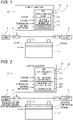
- Fig. 1 is a diagram showing an outline of a battery control apparatus 10 according to an embodiment of the present disclosure.
- the battery control apparatus 10 is a control apparatus that controls charging and discharging of an in-vehicle battery 1, and particularly adjusts an SOC (State Of Charge indicating charge rate or charge state) of the battery 1 during storage.
- SOC State Of Charge indicating charge rate or charge state
- a vehicle on which the battery control apparatus 10 is mounted is a hybrid vehicle or an electric vehicle.
- the battery 1 is provided as a sub power supply, and the high-voltage power supply 2 is provided as a main power supply that supplies electric power to a motor.
- the battery 1 of the present embodiment is a lithium ion battery containing manganese as a positive electrode active material, and supplies electric power to an in-vehicle auxiliary device (electrical component) 4.
- the auxiliary device 4 is an example of a load.
- the power supply 2 and the battery 1 are connected by a power line 5.
- the power line 5 is provided with a switch 3, a DC/DC converter (not shown), and the like.
- a switch 3 When the switch 3 is turned on/off by the battery control apparatus 10, a charge time of the battery 1 is adjusted, and the SOC of the battery 1 is adjusted.
- the battery control apparatus 10 includes a control substrate 12 on which a micro controller unit (MCU) 11 is mounted.
- the MCU 11 is an example of a controller.
- the MCU 11 stores an SOH estimation logic 111 that estimates the State of Health (SOH) of the battery 1, SOH-SOC correlation information 112 that is information on a correlation between the SOH of the battery 1 and the SOC during storage (after deterioration) of the battery 1, and a control logic 113 that controls the charging and discharging of the battery 1.
- SOH-SOC correlation information 112 is an example of correlation information. Information such as an open circuit voltage of the battery 1, an output voltage, an output current, an internal resistance of the battery 1, and an environmental temperature at which the battery 1 is stored is input to the MCU 11.
- the internal resistance of the battery 1 may be calculated by the MCU 11.
- the MCU 11 may include a processor and a memory storing instructions that, when executed by the processor, cause the processor to perform operations by at least one of the SOH estimation logic 111, the SOH-OSC correlation information 112 and the control logic 113.
- the SOH-SOC correlation information 112 may be stored in the memory or may be stored in another storage.
- the SOH estimation logic 111 of the MCU 11 estimates (calculates) the SOH of the battery 1 based on the open circuit voltage of the battery 1, the output voltage, the output current, the internal resistance of the battery 1, and the like.
- various known methods of estimating the SOH by using a temporal change of the SOC or/and a temporal increase of the internal resistance may be used.
- Examples of the method of estimating the SOH include a method based on a charge and discharge test, a method based on a current integration method, a method based on measurement of an open circuit voltage, a method based on measurement of a terminal voltage, a method based on a model (the above is a method using the temporal change of the SOC), a method based on alternating current impedance measurement, a method using an adaptive digital filter based on a model, a method based on linear regression (a slope of a straight line of I-V characteristics) from I-V characteristics (current-voltage characteristics), a method based on a step response (a method of estimating by using the temporal increase of the internal resistance), and the like.
- the SOH-SOC correlation information 112 includes an SOCinitial which is the SOC of the battery 1 in an initial state (that is, the SOH is 100%).
- the SOCinitial is calculated by the following Equation (1).
- SOCinitial SOCmin + Derror
- the SOCmin is a lower limit value of the SOC and is calculated by the following Equation (2).
- the Derror is a detection error.
- SOCmin Cneed / Cfull
- the Cneed is a charge capacity required to satisfy required output of the battery 1 according to a specification of the auxiliary device 4 which is a power supply destination, and the Cfull is an initial full charge capacity of the battery 1.
- the Cneed is an example of a predetermined charge capacity.
- the SOH-SOC correlation information 112 includes an SOCdet (an example of an SOC after deterioration) which is the SOC of the battery 1 during a use period (that is, the SOH is less than 100%).
- the SOCdet is calculated by the following Equation (3).
- SOCdet Cneed / Cfull ⁇ Cdet
- the Cdet is an amount of decrease in the charge capacity due to the deterioration, and is calculated by the following Equation (4).
- the Cfull - Cdet corresponds to a full charge capacity of the battery 1 after the deterioration.
- Cdet 1 ⁇ SOH ⁇ Cfull
- the SOH estimation logic 111 of the MCU 11 estimates the SOH of the battery 1 periodically (for example, every month) during the use period of the battery 1, and the control logic 113 of the MCU 11 calculates the SOCdet corresponding to the SOH estimated by the SOH estimation logic 111 by the above Equation (3). Then, the control logic 113 adjusts the charge time of the battery 1 by the switch 3 such that the SOC of the battery 1 is the SOCdet.
- the SOCinitial which is an initial value of the SOC of the battery 1
- the SOCmin which is the minimum required in relation to the auxiliary machine 4 as the power supply destination. Accordingly, the SOC of the battery 1 in the initial state is suppressed to a necessary minimum, and therefore, the deterioration of the battery 1 can be prevented, and the required output of the battery 1 required in relation to the auxiliary device 4 as the power supply destination can be secured.
- the SOCdet of the battery 1 during the use period is set to a value obtained by dividing the charge capacity Cneed required in relation to the auxiliary machine 4 as the power supply destination by the full charge capacity after the deterioration (a value obtained by subtracting the deterioration amount Cdet of the charge capacity from the initial full charge capacity Cfull).
- the SOC of the battery 1 during the use period is suppressed to the necessary minimum, and therefore, the deterioration of the battery 1 is prevented, and the SOC of the battery 1 during the use period is periodically increased to the SOCdet corresponding to the deterioration of the battery 1, and therefore, the required output of the battery 1 required in relation to the auxiliary machine 4 as the power supply destination can be secured.
- Fig. 2 is a diagram showing an outline of a battery control apparatus 20 according to another embodiment of the present disclosure.
- the battery control apparatus 20 includes a control substrate 22 on which an MCU 21 is mounted.
- the MCU 21 is an example of a controller.
- the MCU 21 stores the SOH estimation logic 111, battery initial information 212 which is information of the battery 1 in an initial state, a deterioration coefficient table 213, and a control logic 214.
- the deterioration coefficient table 213 is an example of correlation information.
- the MCU 21 may include a processor and a memory storing instructions that, when executed by the processor, cause the processor to perform operations by at least one of the SOH estimation logic 111, the battery initial information 212, the deterioration coefficient table 213 and the control logic 214. At least one of the battery initial information 212 and the deterioration coefficient table 213 may be stored in the memory or may be stored in another storage.
- the SOH estimation logic 111 has a function similar to that of the above-described embodiment. Further, the battery initial information 212 includes an SOCinitial which is the SOC of the battery 1 in an initial state (that is, the SOH is 100%). The SOCinitial is calculated by the above Equation (1).
- the deterioration coefficient table 213 is a table indicating information on a correlation among the SOH of the battery 1, the SOC during storage (after deterioration) of the battery 1, a temperature during storage of the battery 1 (hereinafter referred to as a storage temperature), and a deterioration coefficient ksn of the battery 1 (see Fig. 3 ). The details will be described later.
- the SOCinitial for example, 60%
- an SOC for example, 80%
- Fig. 3 is a diagram showing an outline of the deterioration coefficient table 213 of the battery control apparatus 20 shown in Fig. 2 .
- the deterioration coefficient table 213 is a table indicating a relationship among the SOC, the storage temperature, and the deterioration coefficient ksn at a predetermined SOH.
- the predetermined SOH is set every 5%, for example, 95%, 90%, 85%, and so on. That is, a plurality of deterioration coefficient tables 213 are stored in the MCU 21.
- each deterioration coefficient table 213 the SOC is set for every 10%, for example, 100%, 90%, 80%, and so on, and the storage temperature is set for every 5°C, for example, - 30°C, ..., - 5°C, 0°C, 5°C, and so on.
- the deterioration coefficient ksn is set based on a result of a storage test of the battery 1. A larger value of the deterioration coefficient ksn indicates larger deterioration, and a smaller value of the deterioration coefficient ksn indicates smaller deterioration.
- the deterioration coefficient table 213 of a specific SOH corresponding to an SOH from the start of use to the 150th day
- Fig. 4 is a flowchart showing processing performed by the MCU 21 shown in Fig. 2 .
- the control logic 214 of the MCU 21 sets the initial value of the SOC of the new battery 1 to the SOCinitial, and starts the processing.
- the control logic 214 calculates an average value of the storage temperature (environmental temperature) for one day from the use start date of the new battery 1, and stores the average value in a memory (not shown) in association with the SOC.
- step S2 the control logic 214 reads, from the memory, the average value of the storage temperature for one day on the previous day and the SOC on the previous day after the second day from the start of use of the new battery 1, causes the SOH estimation logic 111 to estimate the present SOH of the battery 1, and extracts, from the deterioration coefficient table 213, the deterioration coefficient ksn corresponding to the average value of the storage temperature for one day on the previous day and the SOC on the previous day by referring to the deterioration coefficient table 213 corresponding to the estimated SOH.
- the SOH on the day is 90%
- the average value of the storage temperature on the previous day is 25°C
- the SOC during storage on the previous day is 80%
- step S3 the control logic 214 determines whether the deterioration coefficient ksn extracted in step S2 is a minimum value among a plurality of deterioration coefficients corresponding to the storage temperature on the previous day in the deterioration coefficient table 213 selected in step S2.
- step S4 the processing proceeds to step S4
- step S5 the processing proceeds to step S5.
- step S4 the control logic 214 maintains the SOC of the battery 1 at the SOC on the previous day.
- step S5 the control logic 214 determines whether there is a deterioration coefficient ksn smaller than the deterioration coefficient ksn extracted in step S2 among the plurality of deterioration coefficients ksn corresponding to the storage temperature on the previous day and the SOC equal to or larger than the SOCmin in the deterioration coefficient table 213 selected in step S2.
- step S5 determines whether there is a deterioration coefficient ksn smaller than the deterioration coefficient ksn extracted in step S2 among the plurality of deterioration coefficients ksn corresponding to the storage temperature on the previous day and the SOC equal to or larger than the SOCmin in the deterioration coefficient table 213 selected in step S2.
- step S6 the control logic 214 extracts a deterioration coefficient ksn having a value smaller than the deterioration coefficient ksn extracted in step S2, and extracts the SOC corresponding to the deterioration coefficient ksn from the deterioration coefficient table 213.
- step S7 the control logic 214 sets the SOC of the battery 1 to the SOC (SOCdet) extracted in step S6.
- the above processing (steps S1 to S7) is repeatedly executed.
- the MCU 21 obtains the SOC (SOCdet) after the deterioration based on the deterioration coefficient table 213 indicating the relationship between the predetermined SOH of the battery 1 after the deterioration, the SOC, the storage temperature, and the deterioration coefficient ksn, and adjusts the SOC of the battery 1 to the SOCdet.
- the MCU 21 estimates the SOH of the battery 1 and obtains the storage temperature of the battery 1 during the use period of the battery 1, obtains one or the plurality of deterioration coefficients ksn corresponding to the estimated SOH, the obtained storage temperature, and the SOC equal to or larger than the SOCmin from the deterioration coefficient table 213, and obtains, as the SOCdet, the SOC corresponding to a minimum deterioration coefficient ksn among the obtained one or the plurality of deterioration coefficients ksn.
- the battery control apparatus 20 of the present embodiment sets the SOC (SOCdet) of the battery 1 during storage such that the deterioration coefficient ksn is as small as possible according to the SOH (use period) and the environmental temperature. Accordingly, the deterioration of the battery 1 can be effectively prevented, and the required output of the battery 1 can be secured.
- the deterioration coefficient ksn corresponding to a predetermined storage temperature (for example, 60°C) and a predetermined SOC (for example, 60% or 70%) is set to a value larger than the deterioration coefficient ksn corresponding to the predetermined storage temperature and an SOC (for example, 100%) larger than the predetermined SOC. Accordingly, by setting the SOC of the battery 1 so as to avoid the SOC in which the deterioration specifically progresses with respect to the battery 1 in which the deterioration specifically progresses in the case of the predetermined storage temperature and the predetermined SOC, the deterioration of the battery 1 can be effectively prevented, and the life can be extended.
- a predetermined storage temperature for example, 60°C
- a predetermined SOC for example, 60% or 70%
- the storage temperature is the environmental temperature and an average temperature on the previous day
- other measurement values such as the temperature of the battery 1 itself and a median value of the environmental temperature on the previous day may be used as the storage temperature.
- the initial SOC of the battery 1 is set to the SOCinitial less than 100%, but the initial SOC of the battery 1 may be set to 100%.
- the present disclosure has been described by taking the battery 1 that supplies electric power to the in-vehicle auxiliary device 4 as an example, and the battery of the present disclosure can also be applied to a power battery pack or a 12 V main battery. Further, in the above embodiment, the present disclosure has been described by taking the battery 1, which is a lithium ion battery containing manganese as a positive electrode active material, as an example, but manganese is an example, and the present disclosure can be applied to any battery having a specific SOC in which the progress of the specific deterioration is remarkable.
- a battery control apparatus 10; 20 includes a controller 11; 21 configured to control charging and discharging of a battery 1.
- the controller 11; 21 is configured to: estimate a state of health of the battery 1 to obtain an estimated state of health; obtain, in accordance with relationship information 112; 213 indicating a relationship between a state of health of the battery 1 after deterioration and a state of charge of the battery 1 after the deterioration, a state of charge after deterioration corresponding to the estimated state of health; and adjust the state of charge of the battery 1 to the state of charge after deterioration.
- the battery 1 is configured to supply electric power to a load 4, the state of charge after deterioration is obtained by dividing a predetermined charge capacity by a full charge capacity of the battery 1 after deterioration, and the predetermined charge capacity is a charge capacity that satisfies an output of the battery 1 which is required by the load 4.
- the relationship information 213 includes a table 213 indicating a relationship among the state of health of the battery 1 after the deterioration, the state of charge of the battery 1 after the deterioration, a storage temperature, and a deterioration coefficient, and during a use period of the battery 1, the controller 21 is configured to: obtain the estimated state of health of the battery 1 and obtain a storage temperature of the battery 1; obtain, from the table 213, one or more deterioration coefficients corresponding to the estimated state of health, the obtained storage temperature, and a state of charge equal to or larger than a predetermined lower limit value; and obtain, as the state of charge after the deterioration, a state of charge corresponding to a minimum deterioration coefficient of the one or more deterioration coefficients.
- a deterioration coefficient corresponding to a predetermined storage temperature and a predetermined state of charge is set to a value larger than a deterioration coefficient corresponding to the predetermined storage temperature and a state of charge larger than the predetermined state of charge.
Landscapes
- Engineering & Computer Science (AREA)
- Power Engineering (AREA)
- Physics & Mathematics (AREA)
- General Physics & Mathematics (AREA)
- Secondary Cells (AREA)
- Charge And Discharge Circuits For Batteries Or The Like (AREA)
- Health & Medical Sciences (AREA)
- General Health & Medical Sciences (AREA)
- Medical Informatics (AREA)
- Electric Propulsion And Braking For Vehicles (AREA)
- Tests Of Electric Status Of Batteries (AREA)
Abstract
Description
- The present disclosure relates to a battery control apparatus.
- As a control apparatus for an in-vehicle battery, a control apparatus is known in which by setting a target upper limit value of a remaining capacity of a battery at the time of traveling during traveling of a vehicle and setting a target upper limit value of a remaining capacity of the battery at the time of parking during parking of the vehicle, the remaining capacity of the battery can be controlled to fall within a range in which progress of deterioration can be prevented, and the capacity of the battery can be used in a large range so as to sufficiently secure traveling performance of the vehicle during traveling of the vehicle (for example, refer to Patent Literature 1). In the control apparatus described in
Patent Literature 1, the target upper limit value of the remaining capacity of the battery is set according to a parking time of the vehicle. - Patent Literature 1:
JP-A-2013-074706 - In the control apparatus described in
Patent Literature 1, when the parking time of the vehicle is within one day, the target upper limit value of the remaining capacity of the battery is set to 70% of a full charge amount of the battery, and when the parking time of the vehicle is two days or more and less than three days, the target upper limit value of the remaining capacity of the battery is set to 50% to 60% of the full charge amount of the battery. That is, the target upper limit value of the remaining capacity of the battery is set to be lower as the parking time of the vehicle is longer. However, in a case of a lithium ion battery, since a rated capacity decreases with deterioration, it is necessary to set a charge rate to be high according to the deterioration in order to guarantee the same output. - In view of the above circumstances, an object of the present disclosure is to provide a battery control apparatus capable of preventing deterioration of a battery and securing required output of the battery.
- The present disclosure provides a battery control apparatus including: a controller configured to control charging and discharging of a battery, wherein during a use period of the battery, the controller is configured to: estimate a state of health of the battery to obtain an estimated state of health; obtain, in accordance with relationship information indicating a relationship between a state of health of the battery after deterioration and a state of charge of the battery after deterioration, a state of charge after deterioration corresponding to the estimated state of health; and adjust the state of charge of the battery to the state of charge after deterioration.
- According to the present disclosure, by setting an SOC of a battery according to an SOH, it is possible to prevent deterioration of the battery and to secure required output of the battery.
-
-
Fig. 1 is a diagram showing an outline of a battery control apparatus according to an embodiment of the present disclosure. -
Fig. 2 is a diagram showing an outline of a battery control apparatus according to another embodiment of the present disclosure. -
Fig. 3 is a diagram showing an outline of a deterioration coefficient table of the battery control apparatus shown inFig. 2 . -
Fig. 4 is a flowchart showing processing performed by an MCU shown inFig. 2 . - Hereinafter, the present disclosure will be described in accordance with a preferred embodiment. The present disclosure is not limited to the embodiment to be described below, and can be changed as appropriate without departing from the scope of the present disclosure. Although some configurations are not illustrated or described in the embodiment to be described below, a known or well-known technique is appropriately applied to details of an omitted technique within a range in which no contradiction occurs to contents to be described below.
-
Fig. 1 is a diagram showing an outline of abattery control apparatus 10 according to an embodiment of the present disclosure. As shown in this drawing, thebattery control apparatus 10 is a control apparatus that controls charging and discharging of an in-vehicle battery 1, and particularly adjusts an SOC (State Of Charge indicating charge rate or charge state) of thebattery 1 during storage. - A vehicle on which the
battery control apparatus 10 is mounted is a hybrid vehicle or an electric vehicle. Thebattery 1 is provided as a sub power supply, and the high-voltage power supply 2 is provided as a main power supply that supplies electric power to a motor. Thebattery 1 of the present embodiment is a lithium ion battery containing manganese as a positive electrode active material, and supplies electric power to an in-vehicle auxiliary device (electrical component) 4. Theauxiliary device 4 is an example of a load. - The
power supply 2 and thebattery 1 are connected by apower line 5. Thepower line 5 is provided with aswitch 3, a DC/DC converter (not shown), and the like. When theswitch 3 is turned on/off by thebattery control apparatus 10, a charge time of thebattery 1 is adjusted, and the SOC of thebattery 1 is adjusted. - The
battery control apparatus 10 includes acontrol substrate 12 on which a micro controller unit (MCU) 11 is mounted. The MCU 11 is an example of a controller. TheMCU 11 stores anSOH estimation logic 111 that estimates the State of Health (SOH) of thebattery 1, SOH-SOC correlation information 112 that is information on a correlation between the SOH of thebattery 1 and the SOC during storage (after deterioration) of thebattery 1, and acontrol logic 113 that controls the charging and discharging of thebattery 1. The SOH-SOC correlation information 112 is an example of correlation information. Information such as an open circuit voltage of thebattery 1, an output voltage, an output current, an internal resistance of thebattery 1, and an environmental temperature at which thebattery 1 is stored is input to theMCU 11. The internal resistance of thebattery 1 may be calculated by theMCU 11. The MCU 11 may include a processor and a memory storing instructions that, when executed by the processor, cause the processor to perform operations by at least one of theSOH estimation logic 111, the SOH-OSC correlation information 112 and thecontrol logic 113. The SOH-SOC correlation information 112 may be stored in the memory or may be stored in another storage. - The
SOH estimation logic 111 of theMCU 11 estimates (calculates) the SOH of thebattery 1 based on the open circuit voltage of thebattery 1, the output voltage, the output current, the internal resistance of thebattery 1, and the like. As a method of estimating the SOH, various known methods of estimating the SOH by using a temporal change of the SOC or/and a temporal increase of the internal resistance may be used. Examples of the method of estimating the SOH include a method based on a charge and discharge test, a method based on a current integration method, a method based on measurement of an open circuit voltage, a method based on measurement of a terminal voltage, a method based on a model (the above is a method using the temporal change of the SOC), a method based on alternating current impedance measurement, a method using an adaptive digital filter based on a model, a method based on linear regression (a slope of a straight line of I-V characteristics) from I-V characteristics (current-voltage characteristics), a method based on a step response (a method of estimating by using the temporal increase of the internal resistance), and the like. - The SOH-
SOC correlation information 112 includes an SOCinitial which is the SOC of thebattery 1 in an initial state (that is, the SOH is 100%). The SOCinitial is calculated by the following Equation (1).

battery 1 according to a specification of theauxiliary device 4 which is a power supply destination, and the Cfull is an initial full charge capacity of thebattery 1. The Cneed is an example of a predetermined charge capacity. - Further, the SOH-
SOC correlation information 112 includes an SOCdet (an example of an SOC after deterioration) which is the SOC of thebattery 1 during a use period (that is, the SOH is less than 100%). The SOCdet is calculated by the following Equation (3).
battery 1 after the deterioration.
- The
SOH estimation logic 111 of theMCU 11 estimates the SOH of thebattery 1 periodically (for example, every month) during the use period of thebattery 1, and thecontrol logic 113 of theMCU 11 calculates the SOCdet corresponding to the SOH estimated by theSOH estimation logic 111 by the above Equation (3). Then, thecontrol logic 113 adjusts the charge time of thebattery 1 by theswitch 3 such that the SOC of thebattery 1 is the SOCdet. - That is, in the
battery control apparatus 10 of the present embodiment, the SOCinitial, which is an initial value of the SOC of thebattery 1, is set to a value obtained by adding the detection error Derror to the SOCmin, which is the minimum required in relation to theauxiliary machine 4 as the power supply destination. Accordingly, the SOC of thebattery 1 in the initial state is suppressed to a necessary minimum, and therefore, the deterioration of thebattery 1 can be prevented, and the required output of thebattery 1 required in relation to theauxiliary device 4 as the power supply destination can be secured. - Further, in the
battery control apparatus 10 of the present embodiment, the SOCdet of thebattery 1 during the use period is set to a value obtained by dividing the charge capacity Cneed required in relation to theauxiliary machine 4 as the power supply destination by the full charge capacity after the deterioration (a value obtained by subtracting the deterioration amount Cdet of the charge capacity from the initial full charge capacity Cfull). Accordingly, the SOC of thebattery 1 during the use period is suppressed to the necessary minimum, and therefore, the deterioration of thebattery 1 is prevented, and the SOC of thebattery 1 during the use period is periodically increased to the SOCdet corresponding to the deterioration of thebattery 1, and therefore, the required output of thebattery 1 required in relation to theauxiliary machine 4 as the power supply destination can be secured. -
Fig. 2 is a diagram showing an outline of abattery control apparatus 20 according to another embodiment of the present disclosure. The same reference numerals are given to configurations similar to those of the above-described embodiment, and the description of the above-described embodiments is incorporated. As shown inFig. 2 , thebattery control apparatus 20 includes acontrol substrate 22 on which anMCU 21 is mounted. The MCU 21 is an example of a controller. The MCU 21 stores theSOH estimation logic 111, batteryinitial information 212 which is information of thebattery 1 in an initial state, a deterioration coefficient table 213, and acontrol logic 214. The deterioration coefficient table 213 is an example of correlation information. Further, information such as an open circuit voltage of thebattery 1, an output voltage, an output current, an internal resistance of thebattery 1, and an environmental temperature at which thebattery 1 is stored is input to theMCU 21. The internal resistance of thebattery 1 may be calculated by theMCU 21. TheMCU 21 may include a processor and a memory storing instructions that, when executed by the processor, cause the processor to perform operations by at least one of theSOH estimation logic 111, the batteryinitial information 212, the deterioration coefficient table 213 and thecontrol logic 214. At least one of the batteryinitial information 212 and the deterioration coefficient table 213 may be stored in the memory or may be stored in another storage. - The
SOH estimation logic 111 has a function similar to that of the above-described embodiment. Further, the batteryinitial information 212 includes an SOCinitial which is the SOC of thebattery 1 in an initial state (that is, the SOH is 100%). The SOCinitial is calculated by the above Equation (1). - The deterioration coefficient table 213 is a table indicating information on a correlation among the SOH of the
battery 1, the SOC during storage (after deterioration) of thebattery 1, a temperature during storage of the battery 1 (hereinafter referred to as a storage temperature), and a deterioration coefficient ksn of the battery 1 (seeFig. 3 ). The details will be described later. Thecontrol logic 214 sets the SOC of thebattery 1 in the initial state (SOH = 100%) to the SOCinitial, and after the second day from the start of use, periodically (for example, every day) adjusts the SOC of thebattery 1 during the use period based on the SOH of thebattery 1 estimated by theSOH estimation logic 111, an average value of the obtained storage temperatures, and the deterioration coefficient table 213. - Here, as described in the papers described later, even when the deterioration of the
battery 1 does not progress, the progress of the deterioration is fast at the SOC = 100% at 25°C, but the progress of the deterioration is fast at the SOC = 60% and 70% at 60°C. Therefore, in the present embodiment, even when the deterioration of thebattery 1 does not progress, when the environmental temperature increases, the progress of the deterioration of thebattery 1 is prevented by increasing the SOC of thebattery 1 from the SOCinitial (for example, 60%) to an SOC (for example, 80%) at a high temperature in the drawing. -
Fig. 3 is a diagram showing an outline of the deterioration coefficient table 213 of thebattery control apparatus 20 shown inFig. 2 . As shown in this drawing, the deterioration coefficient table 213 is a table indicating a relationship among the SOC, the storage temperature, and the deterioration coefficient ksn at a predetermined SOH. The predetermined SOH is set every 5%, for example, 95%, 90%, 85%, and so on. That is, a plurality of deterioration coefficient tables 213 are stored in theMCU 21. In each deterioration coefficient table 213, the SOC is set for every 10%, for example, 100%, 90%, 80%, and so on, and the storage temperature is set for every 5°C, for example, - 30°C, ..., - 5°C, 0°C, 5°C, and so on. The deterioration coefficient ksn (ks0, ks1, ks2, ..., ksn, n is an integer of 0 or more) is set for each corresponding SOC and storage temperature, for example, ks0 when the SOC = 100% and the storage temperature is - 30°C, ks32 when the SOC = 90% and the storage temperature is 25°C. - The deterioration coefficient ksn is set based on a result of a storage test of the
battery 1. A larger value of the deterioration coefficient ksn indicates larger deterioration, and a smaller value of the deterioration coefficient ksn indicates smaller deterioration. Here, storage deterioration of a lithium ion battery does not always progress easily as the SOC and the storage temperature during storage are higher, and depending on a battery material, recent studies have shown that the storage deterioration of the lithium ion battery easily progresses when the battery is stored at a specific SOC and a specific storage temperature (JARI Research Journal 20151201, "Calendar Degradation Mechanism of Lithium-ion Batteries with a LiMn2O4 and LiMO2 (M = Co, Ni and Mn) Composite Cathode", Authors: Keisuke ANDO, Tomoyuki MATSUDA, Masao MYOJIN, Daichi IMAMURA). In particular, in a case where manganese is contained in a positive electrode active material, it has been found that when the storage temperature is 25°C, the SOC is 100% and the progress of the deterioration is maximum, but when the storage temperature is 60°C, the SOC is 60% and 70% and the progress of the deterioration is maximum. Further, it has also been found that, in the case where the storage temperature is 60°C, the SOC is 70% and the progress of the deterioration is maximum during a period from the start of use to 150 days, and the SOC is 60% and the progress of the deterioration is maximum after 150 days from the start of use. - That is, it has been found that, in a specific lithium ion battery in which manganese is contained in a positive electrode active material and the like, the progress of specific deterioration is remarkable at a specific SOC lower than 100% at a specific storage temperature, and the progress of the specific deterioration exceeds the progress of the deterioration when the SOC is 100%.
- Therefore, in the deterioration coefficient table 213 of the present embodiment, the deterioration coefficient ksn increases as the SOC and the storage temperature during storage increase, but the deterioration coefficient ksn corresponding to the specific storage temperature and the specific SOC of less than 100% is set to a value larger than the deterioration coefficient ksn corresponding to the specific storage temperature and SOC = 100%. For example, in the deterioration coefficient table 213 of a specific SOH (corresponding to an SOH from the start of use to the 150th day), the deterioration coefficient ksn corresponding to the storage temperature = 60°C and the SOC = 70% is set to a maximum value among the deterioration coefficients ksn corresponding to the storage temperature = 60°C. Alternatively, in the deterioration coefficient table 213 of a specific SOH (corresponding to an SOH after the 150th day from the start of use), the deterioration coefficient ksn corresponding to the storage temperature = 60°C and the SOC = 60% is set to the maximum value among the deterioration coefficients ksn corresponding to the storage temperature = 60°C.
-
Fig. 4 is a flowchart showing processing performed by theMCU 21 shown inFig. 2 . First, thecontrol logic 214 of theMCU 21 sets the initial value of the SOC of thenew battery 1 to the SOCinitial, and starts the processing. Here, the SOCinitial is derived from a table in which the SOH = 100% and the storage temperature is 25°C. In step S1, thecontrol logic 214 calculates an average value of the storage temperature (environmental temperature) for one day from the use start date of thenew battery 1, and stores the average value in a memory (not shown) in association with the SOC. Next, in step S2, thecontrol logic 214 reads, from the memory, the average value of the storage temperature for one day on the previous day and the SOC on the previous day after the second day from the start of use of thenew battery 1, causes theSOH estimation logic 111 to estimate the present SOH of thebattery 1, and extracts, from the deterioration coefficient table 213, the deterioration coefficient ksn corresponding to the average value of the storage temperature for one day on the previous day and the SOC on the previous day by referring to the deterioration coefficient table 213 corresponding to the estimated SOH. For example, when the SOH on the day is 90%, the average value of the storage temperature on the previous day is 25°C, and the SOC during storage on the previous day is 80%, the deterioration coefficient ksn corresponding to the SOC = 80% and the storage temperature = 25°C is extracted from the deterioration coefficient table 213 of the SOH = 90%. - Next, in step S3, the
control logic 214 determines whether the deterioration coefficient ksn extracted in step S2 is a minimum value among a plurality of deterioration coefficients corresponding to the storage temperature on the previous day in the deterioration coefficient table 213 selected in step S2. When an affirmative determination is made in step S3, the processing proceeds to step S4, and when a negative determination is made in step S3, the processing proceeds to step S5. - In step S4, the
control logic 214 maintains the SOC of thebattery 1 at the SOC on the previous day. On the other hand, in step S5, thecontrol logic 214 determines whether there is a deterioration coefficient ksn smaller than the deterioration coefficient ksn extracted in step S2 among the plurality of deterioration coefficients ksn corresponding to the storage temperature on the previous day and the SOC equal to or larger than the SOCmin in the deterioration coefficient table 213 selected in step S2. When an affirmative determination is made in step S5, the processing proceeds to step S6, and when a negative determination is made in step S5, the processing proceeds to step S4. - In step S6, the
control logic 214 extracts a deterioration coefficient ksn having a value smaller than the deterioration coefficient ksn extracted in step S2, and extracts the SOC corresponding to the deterioration coefficient ksn from the deterioration coefficient table 213. Next, in step S7, thecontrol logic 214 sets the SOC of thebattery 1 to the SOC (SOCdet) extracted in step S6. The above processing (steps S1 to S7) is repeatedly executed. - As described above, in the
battery control apparatus 20 of the present embodiment, theMCU 21 obtains the SOC (SOCdet) after the deterioration based on the deterioration coefficient table 213 indicating the relationship between the predetermined SOH of thebattery 1 after the deterioration, the SOC, the storage temperature, and the deterioration coefficient ksn, and adjusts the SOC of thebattery 1 to the SOCdet. Specifically, theMCU 21 estimates the SOH of thebattery 1 and obtains the storage temperature of thebattery 1 during the use period of thebattery 1, obtains one or the plurality of deterioration coefficients ksn corresponding to the estimated SOH, the obtained storage temperature, and the SOC equal to or larger than the SOCmin from the deterioration coefficient table 213, and obtains, as the SOCdet, the SOC corresponding to a minimum deterioration coefficient ksn among the obtained one or the plurality of deterioration coefficients ksn. That is, thebattery control apparatus 20 of the present embodiment sets the SOC (SOCdet) of thebattery 1 during storage such that the deterioration coefficient ksn is as small as possible according to the SOH (use period) and the environmental temperature. Accordingly, the deterioration of thebattery 1 can be effectively prevented, and the required output of thebattery 1 can be secured. - In particular, in the deterioration coefficient table 213 of the present embodiment, the deterioration coefficient ksn corresponding to a predetermined storage temperature (for example, 60°C) and a predetermined SOC (for example, 60% or 70%) is set to a value larger than the deterioration coefficient ksn corresponding to the predetermined storage temperature and an SOC (for example, 100%) larger than the predetermined SOC. Accordingly, by setting the SOC of the
battery 1 so as to avoid the SOC in which the deterioration specifically progresses with respect to thebattery 1 in which the deterioration specifically progresses in the case of the predetermined storage temperature and the predetermined SOC, the deterioration of thebattery 1 can be effectively prevented, and the life can be extended. - Although the present disclosure has been described based on the embodiment, the present disclosure is not limited to the embodiment described above. The present disclosure may be modified as appropriate without departing from the scope of the present disclosure, or known and well-known techniques may be combined as appropriate.
- For example, in the above embodiment, although the storage temperature is the environmental temperature and an average temperature on the previous day, other measurement values such as the temperature of the
battery 1 itself and a median value of the environmental temperature on the previous day may be used as the storage temperature. Further, in the above embodiment, the initial SOC of thebattery 1 is set to the SOCinitial less than 100%, but the initial SOC of thebattery 1 may be set to 100%. - Further, in the above embodiment, the present disclosure has been described by taking the
battery 1 that supplies electric power to the in-vehicleauxiliary device 4 as an example, and the battery of the present disclosure can also be applied to a power battery pack or a 12 V main battery. Further, in the above embodiment, the present disclosure has been described by taking thebattery 1, which is a lithium ion battery containing manganese as a positive electrode active material, as an example, but manganese is an example, and the present disclosure can be applied to any battery having a specific SOC in which the progress of the specific deterioration is remarkable. - As described above, a
battery control apparatus 10; 20 includes acontroller 11; 21 configured to control charging and discharging of abattery 1. During a use period of thebattery 1, thecontroller 11; 21 is configured to: estimate a state of health of thebattery 1 to obtain an estimated state of health; obtain, in accordance withrelationship information 112; 213 indicating a relationship between a state of health of thebattery 1 after deterioration and a state of charge of thebattery 1 after the deterioration, a state of charge after deterioration corresponding to the estimated state of health; and adjust the state of charge of thebattery 1 to the state of charge after deterioration. - In the
battery control apparatus 10, thebattery 1 is configured to supply electric power to aload 4, the state of charge after deterioration is obtained by dividing a predetermined charge capacity by a full charge capacity of thebattery 1 after deterioration, and the predetermined charge capacity is a charge capacity that satisfies an output of thebattery 1 which is required by theload 4. - In the
battery control apparatus 20, therelationship information 213 includes a table 213 indicating a relationship among the state of health of thebattery 1 after the deterioration, the state of charge of thebattery 1 after the deterioration, a storage temperature, and a deterioration coefficient, and during a use period of thebattery 1, thecontroller 21 is configured to: obtain the estimated state of health of thebattery 1 and obtain a storage temperature of thebattery 1; obtain, from the table 213, one or more deterioration coefficients corresponding to the estimated state of health, the obtained storage temperature, and a state of charge equal to or larger than a predetermined lower limit value; and obtain, as the state of charge after the deterioration, a state of charge corresponding to a minimum deterioration coefficient of the one or more deterioration coefficients. - In the
battery control apparatus 20, in the table 213, a deterioration coefficient corresponding to a predetermined storage temperature and a predetermined state of charge is set to a value larger than a deterioration coefficient corresponding to the predetermined storage temperature and a state of charge larger than the predetermined state of charge.
Claims (4)
- A battery control apparatus (10; 20) comprising:a controller (11; 21) configured to control charging and discharging of a battery (1),wherein during a use period of the battery (1), the controller (11; 21) is configured to:estimate a state of health of the battery (1) to obtain an estimated state of health;obtain, in accordance with relationship information (112; 213) indicating a relationship between a state of health of the battery (1) after deterioration and a state of charge of the battery (1) after deterioration, a state of charge after deterioration corresponding to the estimated state of health; andadjust the state of charge of the battery (1) to the state of charge after deterioration.
- The battery control apparatus (10) according to claim 1,wherein the battery (1) is configured to supply electric power to a load (4),wherein the state of charge after deterioration is obtained by dividing a predetermined charge capacity by a full charge capacity of the battery (1) after deterioration, andwherein the predetermined charge capacity is a charge capacity that satisfies an output of the battery (1) which is required by the load (4).
- The battery control apparatus (20) according to claim 1,wherein the relationship information (213) comprises a table (213) indicating a relationship among the state of health of the battery (1) after the deterioration, the state of charge of the battery (1) after deterioration, a storage temperature, and a deterioration coefficient, andwherein during a use period of the battery (1), the controller (21) is configured to:obtain the estimated state of health of the battery (1) and obtain a storage temperature of the battery (1);obtain, from the table (213), one or more deterioration coefficients corresponding to the estimated state of health, the obtained storage temperature, and a state of charge equal to or larger than a predetermined lower limit value; andobtain, as the state of charge after the deterioration, a state of charge corresponding to a minimum deterioration coefficient of the one or more deterioration coefficients.
- The battery control apparatus (20) according to claim 3,
wherein in the table (213), a deterioration coefficient corresponding to a predetermined storage temperature and a predetermined state of charge is set to a value larger than a deterioration coefficient corresponding to the predetermined storage temperature and a state of charge larger than the predetermined state of charge.
Applications Claiming Priority (1)
| Application Number | Priority Date | Filing Date | Title |
|---|---|---|---|
| JP2020211479A JP7344192B2 (en) | 2020-12-21 | 2020-12-21 | battery control device |
Publications (2)
| Publication Number | Publication Date |
|---|---|
| EP4016790A1 true EP4016790A1 (en) | 2022-06-22 |
| EP4016790B1 EP4016790B1 (en) | 2023-01-04 |
Family
ID=78844591
Family Applications (1)
| Application Number | Title | Priority Date | Filing Date |
|---|---|---|---|
| EP21214011.5A Active EP4016790B1 (en) | 2020-12-21 | 2021-12-13 | Battery control apparatus |
Country Status (4)
| Country | Link |
|---|---|
| US (1) | US20220200312A1 (en) |
| EP (1) | EP4016790B1 (en) |
| JP (1) | JP7344192B2 (en) |
| CN (1) | CN114649846B (en) |
Families Citing this family (1)
| Publication number | Priority date | Publication date | Assignee | Title |
|---|---|---|---|---|
| US12296713B2 (en) * | 2022-10-25 | 2025-05-13 | Volvo Car Corporation | Vehicle battery smart range estimation and removable battery cell storage optimization |
Citations (4)
| Publication number | Priority date | Publication date | Assignee | Title |
|---|---|---|---|---|
| JP2013074706A (en) | 2011-09-27 | 2013-04-22 | Honda Motor Co Ltd | Control device for vehicle |
| US20140088898A1 (en) * | 2011-06-02 | 2014-03-27 | Sk Innovation Co., Ltd. | Method for Estimation State of Health for ESS |
| US20150293183A1 (en) * | 2012-11-30 | 2015-10-15 | Sanyo Electric Co., Ltd. | Battery management device, power supply, and soc estimation method |
| CN105548898A (en) * | 2015-12-25 | 2016-05-04 | 华南理工大学 | Lithium battery SOC estimation method of off-line data segmentation correction |
Family Cites Families (7)
| Publication number | Priority date | Publication date | Assignee | Title |
|---|---|---|---|---|
| US9366732B2 (en) * | 2009-09-04 | 2016-06-14 | Board Of Regents, The University Of Texas System | Estimation of state-of-health in batteries |
| KR101399388B1 (en) * | 2010-01-18 | 2014-05-27 | 에스케이이노베이션 주식회사 | Apparatus and Method for estimating the life span of battery |
| US9203122B2 (en) * | 2012-09-28 | 2015-12-01 | Palo Alto Research Center Incorporated | Monitoring and management for energy storage devices |
| JP6648698B2 (en) * | 2014-12-10 | 2020-02-14 | 株式会社Gsユアサ | Energy storage element state estimation device and energy storage element state estimation method |
| KR20170092984A (en) * | 2016-02-04 | 2017-08-14 | 삼성전자주식회사 | Apparatus and method for controlling temperature for battery storage |
| AU2019238652A1 (en) * | 2018-03-20 | 2020-11-12 | Gs Yuasa International Ltd. | Degradation estimation apparatus, computer program, and degradation estimation method |
| JP7039499B2 (en) * | 2019-01-04 | 2022-03-22 | 株式会社東芝 | Internal state estimation device and method, as well as battery control device |
-
2020
- 2020-12-21 JP JP2020211479A patent/JP7344192B2/en active Active
-
2021
- 2021-12-13 EP EP21214011.5A patent/EP4016790B1/en active Active
- 2021-12-20 US US17/556,499 patent/US20220200312A1/en not_active Abandoned
- 2021-12-21 CN CN202111569353.XA patent/CN114649846B/en active Active
Patent Citations (4)
| Publication number | Priority date | Publication date | Assignee | Title |
|---|---|---|---|---|
| US20140088898A1 (en) * | 2011-06-02 | 2014-03-27 | Sk Innovation Co., Ltd. | Method for Estimation State of Health for ESS |
| JP2013074706A (en) | 2011-09-27 | 2013-04-22 | Honda Motor Co Ltd | Control device for vehicle |
| US20150293183A1 (en) * | 2012-11-30 | 2015-10-15 | Sanyo Electric Co., Ltd. | Battery management device, power supply, and soc estimation method |
| CN105548898A (en) * | 2015-12-25 | 2016-05-04 | 华南理工大学 | Lithium battery SOC estimation method of off-line data segmentation correction |
Non-Patent Citations (2)
| Title |
|---|
| KEISUKE ANDOTOMOYUKI MATSUDAMASAO MYOJINDAICHI IMAMURA: "Calendar Degradation Mechanism of Lithium-ion Batteries with a LiMn C> and LiMCh (M = Co, Ni and Mn) Composite Cathode", JARI RESEARCH JOURNAL, vol. 20151201 |
| LAZREG MERIEM BEN ET AL: "Lithium-ion battery pack modeling using accurate OCV model: Application for SoC and SoH estimation", 2020 IEEE 4TH INTERNATIONAL CONFERENCE ON INTELLIGENT ENERGY AND POWER SYSTEMS (IEPS), IEEE, 7 September 2020 (2020-09-07), pages 175 - 179, XP033898147, DOI: 10.1109/IEPS51250.2020.9263207 * |
Also Published As
| Publication number | Publication date |
|---|---|
| JP7344192B2 (en) | 2023-09-13 |
| JP2022098121A (en) | 2022-07-01 |
| CN114649846B (en) | 2025-07-08 |
| US20220200312A1 (en) | 2022-06-23 |
| EP4016790B1 (en) | 2023-01-04 |
| CN114649846A (en) | 2022-06-21 |
Similar Documents
| Publication | Publication Date | Title |
|---|---|---|
| CN113853706B (en) | Apparatus and method for controlling secondary battery operation using relative deterioration of electrodes | |
| KR101608611B1 (en) | Control device for secondary battery, and soc detection method | |
| EP3641095B1 (en) | Battery charging management apparatus and method | |
| EP2192649B1 (en) | Power storage system | |
| KR101611116B1 (en) | Control device for secondary battery, charging control method, and soc detection method | |
| KR101504804B1 (en) | Apparatus and method for estimating state of secondary battery considering aging | |
| EP2717415A1 (en) | Electricity storage system | |
| US20130022843A1 (en) | Assembled battery and method of controlling assembled battery | |
| EP3982140A1 (en) | Device for managing battery and method for managing battery | |
| US20170199250A1 (en) | Apparatus and method for estimating open circuit voltage | |
| US20160028255A1 (en) | Secondary-battery charging system and method and battery pack | |
| EP2731165A1 (en) | Method for manufacturing battery pack and battery pack | |
| JP2009038876A (en) | Voltage equalization device for battery pack | |
| CN105659428A (en) | Cell system | |
| KR101355973B1 (en) | Apparatus and method for estimationg state of secondary battery | |
| JP2010086901A (en) | Deterioration diagnosing device and degradation diagnosing method of lithium secondary battery | |
| KR20180031206A (en) | Battery management system and method for protecting a battery from over-discharge | |
| JP6822358B2 (en) | Rechargeable battery system | |
| CN110277595A (en) | Secondary battery system and secondary cell control method | |
| US12301036B2 (en) | Management apparatus for energy storage device, energy storage apparatus, and input/output control method for energy storage device | |
| EP4016790B1 (en) | Battery control apparatus | |
| CN113424354A (en) | Battery pack charging method, battery pack, and power supply device | |
| KR102404274B1 (en) | Apparatus and method for adjusting charging or discharging voltage of battery | |
| JP2022139652A (en) | power storage device | |
| JPH04123771A (en) | Charging method |
Legal Events
| Date | Code | Title | Description |
|---|---|---|---|
| PUAI | Public reference made under article 153(3) epc to a published international application that has entered the european phase |
Free format text: ORIGINAL CODE: 0009012 |
|
| STAA | Information on the status of an ep patent application or granted ep patent |
Free format text: STATUS: REQUEST FOR EXAMINATION WAS MADE |
|
| 17P | Request for examination filed |
Effective date: 20211213 |
|
| AK | Designated contracting states |
Kind code of ref document: A1 Designated state(s): AL AT BE BG CH CY CZ DE DK EE ES FI FR GB GR HR HU IE IS IT LI LT LU LV MC MK MT NL NO PL PT RO RS SE SI SK SM TR |
|
| RIC1 | Information provided on ipc code assigned before grant |
Ipc: H02J 7/00 20060101AFI20220907BHEP |
|
| GRAP | Despatch of communication of intention to grant a patent |
Free format text: ORIGINAL CODE: EPIDOSNIGR1 |
|
| STAA | Information on the status of an ep patent application or granted ep patent |
Free format text: STATUS: GRANT OF PATENT IS INTENDED |
|
| GRAS | Grant fee paid |
Free format text: ORIGINAL CODE: EPIDOSNIGR3 |
|
| INTG | Intention to grant announced |
Effective date: 20221024 |
|
| GRAA | (expected) grant |
Free format text: ORIGINAL CODE: 0009210 |
|
| STAA | Information on the status of an ep patent application or granted ep patent |
Free format text: STATUS: THE PATENT HAS BEEN GRANTED |
|
| AK | Designated contracting states |
Kind code of ref document: B1 Designated state(s): AL AT BE BG CH CY CZ DE DK EE ES FI FR GB GR HR HU IE IS IT LI LT LU LV MC MK MT NL NO PL PT RO RS SE SI SK SM TR |
|
| REG | Reference to a national code |
Ref country code: GB Ref legal event code: FG4D |
|
| REG | Reference to a national code |
Ref country code: CH Ref legal event code: EP |
|
| REG | Reference to a national code |
Ref country code: AT Ref legal event code: REF Ref document number: 1542628 Country of ref document: AT Kind code of ref document: T Effective date: 20230115 |
|
| REG | Reference to a national code |
Ref country code: DE Ref legal event code: R096 Ref document number: 602021001164 Country of ref document: DE |
|
| REG | Reference to a national code |
Ref country code: IE Ref legal event code: FG4D |
|
| REG | Reference to a national code |
Ref country code: LT Ref legal event code: MG9D |
|
| REG | Reference to a national code |
Ref country code: NL Ref legal event code: MP Effective date: 20230104 |
|
| RAP4 | Party data changed (patent owner data changed or rights of a patent transferred) |
Owner name: YAZAKI CORPORATION |
|
| REG | Reference to a national code |
Ref country code: AT Ref legal event code: MK05 Ref document number: 1542628 Country of ref document: AT Kind code of ref document: T Effective date: 20230104 |
|
| PG25 | Lapsed in a contracting state [announced via postgrant information from national office to epo] |
Ref country code: NL Free format text: LAPSE BECAUSE OF FAILURE TO SUBMIT A TRANSLATION OF THE DESCRIPTION OR TO PAY THE FEE WITHIN THE PRESCRIBED TIME-LIMIT Effective date: 20230104 |
|
| PG25 | Lapsed in a contracting state [announced via postgrant information from national office to epo] |
Ref country code: RS Free format text: LAPSE BECAUSE OF FAILURE TO SUBMIT A TRANSLATION OF THE DESCRIPTION OR TO PAY THE FEE WITHIN THE PRESCRIBED TIME-LIMIT Effective date: 20230104 Ref country code: PT Free format text: LAPSE BECAUSE OF FAILURE TO SUBMIT A TRANSLATION OF THE DESCRIPTION OR TO PAY THE FEE WITHIN THE PRESCRIBED TIME-LIMIT Effective date: 20230504 Ref country code: NO Free format text: LAPSE BECAUSE OF FAILURE TO SUBMIT A TRANSLATION OF THE DESCRIPTION OR TO PAY THE FEE WITHIN THE PRESCRIBED TIME-LIMIT Effective date: 20230404 Ref country code: LV Free format text: LAPSE BECAUSE OF FAILURE TO SUBMIT A TRANSLATION OF THE DESCRIPTION OR TO PAY THE FEE WITHIN THE PRESCRIBED TIME-LIMIT Effective date: 20230104 Ref country code: LT Free format text: LAPSE BECAUSE OF FAILURE TO SUBMIT A TRANSLATION OF THE DESCRIPTION OR TO PAY THE FEE WITHIN THE PRESCRIBED TIME-LIMIT Effective date: 20230104 Ref country code: HR Free format text: LAPSE BECAUSE OF FAILURE TO SUBMIT A TRANSLATION OF THE DESCRIPTION OR TO PAY THE FEE WITHIN THE PRESCRIBED TIME-LIMIT Effective date: 20230104 Ref country code: ES Free format text: LAPSE BECAUSE OF FAILURE TO SUBMIT A TRANSLATION OF THE DESCRIPTION OR TO PAY THE FEE WITHIN THE PRESCRIBED TIME-LIMIT Effective date: 20230104 Ref country code: AT Free format text: LAPSE BECAUSE OF FAILURE TO SUBMIT A TRANSLATION OF THE DESCRIPTION OR TO PAY THE FEE WITHIN THE PRESCRIBED TIME-LIMIT Effective date: 20230104 |
|
| PG25 | Lapsed in a contracting state [announced via postgrant information from national office to epo] |
Ref country code: SE Free format text: LAPSE BECAUSE OF FAILURE TO SUBMIT A TRANSLATION OF THE DESCRIPTION OR TO PAY THE FEE WITHIN THE PRESCRIBED TIME-LIMIT Effective date: 20230104 Ref country code: PL Free format text: LAPSE BECAUSE OF FAILURE TO SUBMIT A TRANSLATION OF THE DESCRIPTION OR TO PAY THE FEE WITHIN THE PRESCRIBED TIME-LIMIT Effective date: 20230104 Ref country code: IS Free format text: LAPSE BECAUSE OF FAILURE TO SUBMIT A TRANSLATION OF THE DESCRIPTION OR TO PAY THE FEE WITHIN THE PRESCRIBED TIME-LIMIT Effective date: 20230504 Ref country code: GR Free format text: LAPSE BECAUSE OF FAILURE TO SUBMIT A TRANSLATION OF THE DESCRIPTION OR TO PAY THE FEE WITHIN THE PRESCRIBED TIME-LIMIT Effective date: 20230405 Ref country code: FI Free format text: LAPSE BECAUSE OF FAILURE TO SUBMIT A TRANSLATION OF THE DESCRIPTION OR TO PAY THE FEE WITHIN THE PRESCRIBED TIME-LIMIT Effective date: 20230104 |
|
| REG | Reference to a national code |
Ref country code: DE Ref legal event code: R097 Ref document number: 602021001164 Country of ref document: DE |
|
| PG25 | Lapsed in a contracting state [announced via postgrant information from national office to epo] |
Ref country code: SM Free format text: LAPSE BECAUSE OF FAILURE TO SUBMIT A TRANSLATION OF THE DESCRIPTION OR TO PAY THE FEE WITHIN THE PRESCRIBED TIME-LIMIT Effective date: 20230104 Ref country code: RO Free format text: LAPSE BECAUSE OF FAILURE TO SUBMIT A TRANSLATION OF THE DESCRIPTION OR TO PAY THE FEE WITHIN THE PRESCRIBED TIME-LIMIT Effective date: 20230104 Ref country code: EE Free format text: LAPSE BECAUSE OF FAILURE TO SUBMIT A TRANSLATION OF THE DESCRIPTION OR TO PAY THE FEE WITHIN THE PRESCRIBED TIME-LIMIT Effective date: 20230104 Ref country code: DK Free format text: LAPSE BECAUSE OF FAILURE TO SUBMIT A TRANSLATION OF THE DESCRIPTION OR TO PAY THE FEE WITHIN THE PRESCRIBED TIME-LIMIT Effective date: 20230104 Ref country code: CZ Free format text: LAPSE BECAUSE OF FAILURE TO SUBMIT A TRANSLATION OF THE DESCRIPTION OR TO PAY THE FEE WITHIN THE PRESCRIBED TIME-LIMIT Effective date: 20230104 |
|
| PLBE | No opposition filed within time limit |
Free format text: ORIGINAL CODE: 0009261 |
|
| STAA | Information on the status of an ep patent application or granted ep patent |
Free format text: STATUS: NO OPPOSITION FILED WITHIN TIME LIMIT |
|
| PG25 | Lapsed in a contracting state [announced via postgrant information from national office to epo] |
Ref country code: SK Free format text: LAPSE BECAUSE OF FAILURE TO SUBMIT A TRANSLATION OF THE DESCRIPTION OR TO PAY THE FEE WITHIN THE PRESCRIBED TIME-LIMIT Effective date: 20230104 |
|
| 26N | No opposition filed |
Effective date: 20231005 |
|
| PG25 | Lapsed in a contracting state [announced via postgrant information from national office to epo] |
Ref country code: SI Free format text: LAPSE BECAUSE OF FAILURE TO SUBMIT A TRANSLATION OF THE DESCRIPTION OR TO PAY THE FEE WITHIN THE PRESCRIBED TIME-LIMIT Effective date: 20230104 |
|
| PG25 | Lapsed in a contracting state [announced via postgrant information from national office to epo] |
Ref country code: IT Free format text: LAPSE BECAUSE OF FAILURE TO SUBMIT A TRANSLATION OF THE DESCRIPTION OR TO PAY THE FEE WITHIN THE PRESCRIBED TIME-LIMIT Effective date: 20230104 |
|
| PG25 | Lapsed in a contracting state [announced via postgrant information from national office to epo] |
Ref country code: LU Free format text: LAPSE BECAUSE OF NON-PAYMENT OF DUE FEES Effective date: 20231213 |
|
| PG25 | Lapsed in a contracting state [announced via postgrant information from national office to epo] |
Ref country code: MC Free format text: LAPSE BECAUSE OF FAILURE TO SUBMIT A TRANSLATION OF THE DESCRIPTION OR TO PAY THE FEE WITHIN THE PRESCRIBED TIME-LIMIT Effective date: 20230104 |
|
| REG | Reference to a national code |
Ref country code: BE Ref legal event code: MM Effective date: 20231231 |
|
| PG25 | Lapsed in a contracting state [announced via postgrant information from national office to epo] |
Ref country code: MC Free format text: LAPSE BECAUSE OF FAILURE TO SUBMIT A TRANSLATION OF THE DESCRIPTION OR TO PAY THE FEE WITHIN THE PRESCRIBED TIME-LIMIT Effective date: 20230104 Ref country code: LU Free format text: LAPSE BECAUSE OF NON-PAYMENT OF DUE FEES Effective date: 20231213 |
|
| REG | Reference to a national code |
Ref country code: IE Ref legal event code: MM4A |
|
| PG25 | Lapsed in a contracting state [announced via postgrant information from national office to epo] |
Ref country code: IE Free format text: LAPSE BECAUSE OF NON-PAYMENT OF DUE FEES Effective date: 20231213 |
|
| PG25 | Lapsed in a contracting state [announced via postgrant information from national office to epo] |
Ref country code: BE Free format text: LAPSE BECAUSE OF NON-PAYMENT OF DUE FEES Effective date: 20231231 |
|
| PG25 | Lapsed in a contracting state [announced via postgrant information from national office to epo] |
Ref country code: FR Free format text: LAPSE BECAUSE OF NON-PAYMENT OF DUE FEES Effective date: 20231231 |
|
| PG25 | Lapsed in a contracting state [announced via postgrant information from national office to epo] |
Ref country code: IE Free format text: LAPSE BECAUSE OF NON-PAYMENT OF DUE FEES Effective date: 20231213 Ref country code: FR Free format text: LAPSE BECAUSE OF NON-PAYMENT OF DUE FEES Effective date: 20231231 Ref country code: BE Free format text: LAPSE BECAUSE OF NON-PAYMENT OF DUE FEES Effective date: 20231231 |
|
| PG25 | Lapsed in a contracting state [announced via postgrant information from national office to epo] |
Ref country code: BG Free format text: LAPSE BECAUSE OF FAILURE TO SUBMIT A TRANSLATION OF THE DESCRIPTION OR TO PAY THE FEE WITHIN THE PRESCRIBED TIME-LIMIT Effective date: 20230104 |
|
| PG25 | Lapsed in a contracting state [announced via postgrant information from national office to epo] |
Ref country code: BG Free format text: LAPSE BECAUSE OF FAILURE TO SUBMIT A TRANSLATION OF THE DESCRIPTION OR TO PAY THE FEE WITHIN THE PRESCRIBED TIME-LIMIT Effective date: 20230104 |
|
| PG25 | Lapsed in a contracting state [announced via postgrant information from national office to epo] |
Ref country code: CY Free format text: LAPSE BECAUSE OF FAILURE TO SUBMIT A TRANSLATION OF THE DESCRIPTION OR TO PAY THE FEE WITHIN THE PRESCRIBED TIME-LIMIT; INVALID AB INITIO Effective date: 20211213 |
|
| REG | Reference to a national code |
Ref country code: CH Ref legal event code: PL |
|
| PG25 | Lapsed in a contracting state [announced via postgrant information from national office to epo] |
Ref country code: CH Free format text: LAPSE BECAUSE OF NON-PAYMENT OF DUE FEES Effective date: 20241231 |
|
| PG25 | Lapsed in a contracting state [announced via postgrant information from national office to epo] |
Ref country code: TR Free format text: LAPSE BECAUSE OF FAILURE TO SUBMIT A TRANSLATION OF THE DESCRIPTION OR TO PAY THE FEE WITHIN THE PRESCRIBED TIME-LIMIT Effective date: 20230104 |
|
| PGFP | Annual fee paid to national office [announced via postgrant information from national office to epo] |
Ref country code: DE Payment date: 20251028 Year of fee payment: 5 |
|
| PG25 | Lapsed in a contracting state [announced via postgrant information from national office to epo] |
Ref country code: HU Free format text: LAPSE BECAUSE OF FAILURE TO SUBMIT A TRANSLATION OF THE DESCRIPTION OR TO PAY THE FEE WITHIN THE PRESCRIBED TIME-LIMIT; INVALID AB INITIO Effective date: 20211213 |