EP4016785A1 - Central battery emergency lighting system - Google Patents
Central battery emergency lighting system Download PDFInfo
- Publication number
- EP4016785A1 EP4016785A1 EP20215864.8A EP20215864A EP4016785A1 EP 4016785 A1 EP4016785 A1 EP 4016785A1 EP 20215864 A EP20215864 A EP 20215864A EP 4016785 A1 EP4016785 A1 EP 4016785A1
- Authority
- EP
- European Patent Office
- Prior art keywords
- emergency
- energy storage
- lighting system
- emergency lighting
- storage means
- Prior art date
- Legal status (The legal status is an assumption and is not a legal conclusion. Google has not performed a legal analysis and makes no representation as to the accuracy of the status listed.)
- Pending
Links
Images
Classifications
-
- H—ELECTRICITY
- H02—GENERATION; CONVERSION OR DISTRIBUTION OF ELECTRIC POWER
- H02J—CIRCUIT ARRANGEMENTS OR SYSTEMS FOR SUPPLYING OR DISTRIBUTING ELECTRIC POWER; SYSTEMS FOR STORING ELECTRIC ENERGY
- H02J7/00—Circuit arrangements for charging or depolarising batteries or for supplying loads from batteries
- H02J7/34—Parallel operation in networks using both storage and other dc sources, e.g. providing buffering
- H02J7/35—Parallel operation in networks using both storage and other dc sources, e.g. providing buffering with light sensitive cells
-
- H—ELECTRICITY
- H02—GENERATION; CONVERSION OR DISTRIBUTION OF ELECTRIC POWER
- H02J—CIRCUIT ARRANGEMENTS OR SYSTEMS FOR SUPPLYING OR DISTRIBUTING ELECTRIC POWER; SYSTEMS FOR STORING ELECTRIC ENERGY
- H02J7/00—Circuit arrangements for charging or depolarising batteries or for supplying loads from batteries
- H02J7/0047—Circuit arrangements for charging or depolarising batteries or for supplying loads from batteries with monitoring or indicating devices or circuits
- H02J7/0048—Detection of remaining charge capacity or state of charge [SOC]
-
- H—ELECTRICITY
- H02—GENERATION; CONVERSION OR DISTRIBUTION OF ELECTRIC POWER
- H02J—CIRCUIT ARRANGEMENTS OR SYSTEMS FOR SUPPLYING OR DISTRIBUTING ELECTRIC POWER; SYSTEMS FOR STORING ELECTRIC ENERGY
- H02J7/00—Circuit arrangements for charging or depolarising batteries or for supplying loads from batteries
- H02J7/007—Regulation of charging or discharging current or voltage
- H02J7/00712—Regulation of charging or discharging current or voltage the cycle being controlled or terminated in response to electric parameters
- H02J7/00714—Regulation of charging or discharging current or voltage the cycle being controlled or terminated in response to electric parameters in response to battery charging or discharging current
- H02J7/00716—Regulation of charging or discharging current or voltage the cycle being controlled or terminated in response to electric parameters in response to battery charging or discharging current in response to integrated charge or discharge current
-
- H—ELECTRICITY
- H02—GENERATION; CONVERSION OR DISTRIBUTION OF ELECTRIC POWER
- H02J—CIRCUIT ARRANGEMENTS OR SYSTEMS FOR SUPPLYING OR DISTRIBUTING ELECTRIC POWER; SYSTEMS FOR STORING ELECTRIC ENERGY
- H02J9/00—Circuit arrangements for emergency or stand-by power supply, e.g. for emergency lighting
- H02J9/002—Circuit arrangements for emergency or stand-by power supply, e.g. for emergency lighting in which a reserve is maintained in an energy source by disconnecting non-critical loads, e.g. maintaining a reserve of charge in a vehicle battery for starting an engine
-
- H—ELECTRICITY
- H02—GENERATION; CONVERSION OR DISTRIBUTION OF ELECTRIC POWER
- H02J—CIRCUIT ARRANGEMENTS OR SYSTEMS FOR SUPPLYING OR DISTRIBUTING ELECTRIC POWER; SYSTEMS FOR STORING ELECTRIC ENERGY
- H02J9/00—Circuit arrangements for emergency or stand-by power supply, e.g. for emergency lighting
- H02J9/04—Circuit arrangements for emergency or stand-by power supply, e.g. for emergency lighting in which the distribution system is disconnected from the normal source and connected to a standby source
- H02J9/06—Circuit arrangements for emergency or stand-by power supply, e.g. for emergency lighting in which the distribution system is disconnected from the normal source and connected to a standby source with automatic change-over, e.g. UPS systems
- H02J9/062—Circuit arrangements for emergency or stand-by power supply, e.g. for emergency lighting in which the distribution system is disconnected from the normal source and connected to a standby source with automatic change-over, e.g. UPS systems for AC powered loads
- H02J9/065—Circuit arrangements for emergency or stand-by power supply, e.g. for emergency lighting in which the distribution system is disconnected from the normal source and connected to a standby source with automatic change-over, e.g. UPS systems for AC powered loads for lighting purposes
-
- Y—GENERAL TAGGING OF NEW TECHNOLOGICAL DEVELOPMENTS; GENERAL TAGGING OF CROSS-SECTIONAL TECHNOLOGIES SPANNING OVER SEVERAL SECTIONS OF THE IPC; TECHNICAL SUBJECTS COVERED BY FORMER USPC CROSS-REFERENCE ART COLLECTIONS [XRACs] AND DIGESTS
- Y02—TECHNOLOGIES OR APPLICATIONS FOR MITIGATION OR ADAPTATION AGAINST CLIMATE CHANGE
- Y02E—REDUCTION OF GREENHOUSE GAS [GHG] EMISSIONS, RELATED TO ENERGY GENERATION, TRANSMISSION OR DISTRIBUTION
- Y02E10/00—Energy generation through renewable energy sources
- Y02E10/50—Photovoltaic [PV] energy
- Y02E10/56—Power conversion systems, e.g. maximum power point trackers
Definitions
- the present disclosure relates to lighting technology, and in particular to an emergency lighting system, a method of operating the same, and a control unit for the same.
- Emergency lighting systems maintain a level of emergency illumination when grid power fails.
- exemplary emergency lighting systems may rely on a central battery or a plurality of individual batteries charged by grid power.
- no level of emergency illumination can be maintained if mains power ceases to work and the one or more batteries become depleted.
- such emergency lighting systems fully depend on an availability of grid power.
- the object of the present invention is thus to provide an emergency lighting system capable of sustained maintenance of a level of emergency illumination when grid power fails.
- an emergency lighting (EL) system comprises energy storage means; and an emergency lighting driver.
- the energy storage means is chargeable by a photovoltaic (PV) system and/or a power grid connectable to the emergency lighting system; and operable above a state of charge (SOC) threshold under non-emergency conditions.
- the emergency lighting driver is operable to drive lighting means connectable to the emergency lighting system off the energy storage means in response to emergency conditions, using a charge below the SOC threshold reserved for emergency response.
- the energy storage means may comprise a modular energy storage means.
- the energy storage means may be located remotely from the emergency lighting driver.
- the energy storage means may comprise a rechargeable battery.
- the energy storage means may comprise a solar battery.
- the emergency lighting system may further be configured to communicate with a battery management unit of and connectable to the energy storage means so as to establish the SOC threshold, an SOC and/or a testing status of the energy storage means.
- the energy storage means may be chargeable by the power grid in response to a price of grid supply below a threshold.
- the energy storage means may be dischargeable to the power grid in response to a peak load signaled by the power grid.
- the emergency lighting system may be operable under non-emergency conditions to drive the lighting means or other loads off the energy storage means, using the charge above the SOC threshold.
- the SOC threshold may comprise an SOC of 10%, preferably 20%, and more preferably 30%.
- the emergency conditions may comprise a failure of the power grid.
- the emergency lighting driver may be operable to drive the lighting means for a period in excess of a multiple of a legally required emergency service time in dependence of the SOC of the energy storage means.
- a method of operating an emergency lighting system comprising energy storage means.
- the method comprises charging the energy storage means by a photovoltaic system and/or a power grid connectable to the emergency lighting system; operating the energy storage means above a state of charge under non-emergency conditions; and driving lighting means connectable to the emergency lighting system off the energy storage means in response to emergency conditions, using a charge below the SOC reserved for emergency response.
- the method may be performed by an emergency lighting system of the first aspect or any of its embodiments.
- a control unit for an emergency lighting system is provided.
- the control unit is designed for implementing the method of the second aspect or any of its embodiments.
- the present invention provides an EL system that
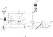
- Fig. 1 illustrates an emergency lighting system 1 according to an embodiment of the present disclosure.
- the emergency lighting system 1 comprises energy storage means 101 and an emergency lighting driver 105.
- the emergency lighting system 1 may further comprise lighting means 106 connectable to the emergency lighting system 1.
- the emergency lighting driver 105 may be an AC/DC converter, for example being able to operate the lighting means either from AC or DC supply.
- the energy storage means 101 may comprise a modular energy storage means 101.
- This may provide a higher degree of reliability (i.e., structural redundancy), and may enable taking advantage of scalability instead of using 12V lead (Pb) acid batteries in series even when not using a PV system.
- the energy storage means 101 may be located remotely from the emergency lighting driver 105; may comprise a rechargeable battery, and may in particular comprise a solar battery.
- This may enable linking up with energy storage means 101 already installed in a building, provide a higher degree of self-sufficiency, as self-produced energy is used, and provide an environmentally friendly EL system powered by solar power.
- Such energy storage means 101 are typically not discharged to SOC values close to 0%, but operated above an SOC threshold ranging between about 10% and 30% in order to maximize a service life of the energy storage means 101.
- SOC threshold ranging between about 10% and 30% in order to maximize a service life of the energy storage means 101.
- a charge below the SOC threshold is typically more than sufficient for emergency lighting.
- the SOC threshold 104 may comprise an SOC of 10%, preferably 20%, and more preferably 30%. The higher the applicable SOC threshold 104, the more capacity may be reserved for emergency response.
- the emergency lighting system 1 is operable under non-emergency (i.e., normal) conditions as well as under emergency conditions, which may comprise a failure of the power grid 103, in particular.
- the energy storage means 101 is operable above the SOC threshold 104.
- the energy storage means 101 may be chargeable by the power grid 103 in response to a price of grid supply below a threshold.
- a price threshold of 0,- € charging may take place in response to a negative price of grid supply, for example.
- charging may occur in response to a low price of grid supply.
- the energy storage means 101 may further be dischargeable to the power grid 103 in response to a peak load signaled by the power grid 103, for example.
- the emergency lighting system 1 may be operable to drive the lighting means 106 (such as LED luminaires, or other loads) off the energy storage means 101, using the charge above the SOC threshold 104.
- the lighting means 106 can as well be operated directly off the power grid 103.
- One main task of the emergency lighting system 1 is therefore to decide whether the loads are operated directly from the power grid 103 or from the connected energy storage means 101. It therefore may comprise a load switch 108 to select the appropriate supply 101, 103.
- the emergency lighting driver 105 is operable to drive the lighting means 106 (depicted on a right portion of Fig. 1 ) off the energy storage means 101, using a charge below the SOC threshold 104 reserved for emergency response.
- the emergency lighting driver 105 may be operable to drive the lighting means 106 for a period in excess of a multiple of a legally required emergency service time in dependence of the SOC of the energy storage means 101.
- the emergency lighting system 1 may further comprise a battery management unit 107 (depicted on a top-left portion of Fig. 1 ) of and connectable to the energy storage means 101.
- the emergency lighting system 1 may be configured to communicate with this battery management unit 107 so as to establish the SOC threshold 104, an SOC and/or a testing status of the energy storage means 101.
- PV and EL system may share its capacity by reserving a fraction thereof for emergency response.
- Such a communication on status and legally required testing may be mandated by a logical and/or spatial separation of the EL system 1 and the battery management 107.
- the battery management 107 may manage the energy storage means 101 and reserve the capacity needed for emergency response, while the EL system 1 may manage the lighting means 106 and perform the required testing and documentation.
- the emergency lighting system 1 may further comprise a control unit 109 for the emergency lighting system 1.
- the control unit 109 may be designed for implementing a method 2 according to a second aspect of the present disclosure or any of its embodiments, which will be explained next.
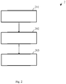
- Fig. 2 illustrates a method 2 of operating an emergency lighting system 1 comprising energy storage means 101 according to an embodiment of the present disclosure.
- the method 2 comprises basic steps of charging 201, operating 202 and driving 203.
- Step 201 involves charging the energy storage means 101 by a photovoltaic system 102 and/or a power grid 103 connectable to the emergency lighting system 1.
- Step 202 involves operating the energy storage means 101 above a state of charge SOC under non-emergency conditions.
- Step 203 involves driving lighting means 106 connectable to the emergency lighting system 1 off the energy storage means 101 in response to emergency conditions, using a charge below the SOC reserved for emergency response.
- the method 2 may be performed by an emergency lighting system 1 according to a first aspect of the present disclosure or any of its embodiments.
Abstract
Description
- The present disclosure relates to lighting technology, and in particular to an emergency lighting system, a method of operating the same, and a control unit for the same.
- Emergency lighting systems maintain a level of emergency illumination when grid power fails. To this end, exemplary emergency lighting systems may rely on a central battery or a plurality of individual batteries charged by grid power. However, no level of emergency illumination can be maintained if mains power ceases to work and the one or more batteries become depleted. Evidently, such emergency lighting systems fully depend on an availability of grid power.
- The object of the present invention is thus to provide an emergency lighting system capable of sustained maintenance of a level of emergency illumination when grid power fails.
- The invention is defined by the appended independent claims. Preferred embodiments are set forth in the dependent claims and in the following description and drawings.
- According to a first aspect of the present disclosure, an emergency lighting (EL) system is provided. The emergency lighting system comprises energy storage means; and an emergency lighting driver. The energy storage means is chargeable by a photovoltaic (PV) system and/or a power grid connectable to the emergency lighting system; and operable above a state of charge (SOC) threshold under non-emergency conditions. The emergency lighting driver is operable to drive lighting means connectable to the emergency lighting system off the energy storage means in response to emergency conditions, using a charge below the SOC threshold reserved for emergency response.
- The energy storage means may comprise a modular energy storage means.
- The energy storage means may be located remotely from the emergency lighting driver.
- The energy storage means may comprise a rechargeable battery.
- The energy storage means may comprise a solar battery.
- The emergency lighting system may further be configured to communicate with a battery management unit of and connectable to the energy storage means so as to establish the SOC threshold, an SOC and/or a testing status of the energy storage means.
- The energy storage means may be chargeable by the power grid in response to a price of grid supply below a threshold.
- The energy storage means may be dischargeable to the power grid in response to a peak load signaled by the power grid.
- The emergency lighting system may be operable under non-emergency conditions to drive the lighting means or other loads off the energy storage means, using the charge above the SOC threshold.
- The SOC threshold may comprise an SOC of 10%, preferably 20%, and more preferably 30%.
- The emergency conditions may comprise a failure of the power grid.
- The emergency lighting system may further comprise at least one of the lighting means and the battery management unit.
- The emergency lighting driver may be operable to drive the lighting means for a period in excess of a multiple of a legally required emergency service time in dependence of the SOC of the energy storage means.
- According to a second aspect of the present disclosure, a method of operating an emergency lighting system comprising energy storage means is provided. The method comprises charging the energy storage means by a photovoltaic system and/or a power grid connectable to the emergency lighting system; operating the energy storage means above a state of charge under non-emergency conditions; and driving lighting means connectable to the emergency lighting system off the energy storage means in response to emergency conditions, using a charge below the SOC reserved for emergency response.
- The method may be performed by an emergency lighting system of the first aspect or any of its embodiments.
- According to a third aspect of the present disclosure, a control unit for an emergency lighting system is provided. The control unit is designed for implementing the method of the second aspect or any of its embodiments.
- The present invention provides an EL system that
- requires only one high-capacity battery system per building (sharing between PV and EL systems; reserving a fraction of the battery capacity for emergency response),
- provides a higher degree of reliability (structural redundancy of modular building batteries),
- provides a higher degree of self-sufficiency (use of self-produced energy),
- is environmentally friendly (EL system powered by solar power),
- is cost-effective, especially when the building already has a PV system,
- enables participation in proactive energy management in accordance with a Smart Grid (charging from and discharging to the power grid as needed), and not least
- sustainably maintains a level of emergency illumination when grid power fails (buffering by high-capacity battery system; during daytime the photovoltaic system can still provide energy and extend a service time of the EL system).
- Further aspects, advantages and objects of the invention will become evident for the skilled reader by means of the following detailed description of the embodiments of the invention, when taking into conjunction with the figures of the enclosed drawings.
-
Fig. 1 illustrates an emergency lighting system according to an embodiment of the present disclosure; and -
Fig. 2 illustrates a method of operating an emergency lighting system comprising energy storage means 101 according to an embodiment of the present disclosure. - The invention will now be described with respect to various embodiments.
- The drawings are to be regarded as being schematic representations and elements illustrated in the drawings are not necessarily shown to scale. Rather, the various elements are represented such that their function and general purpose become apparent to a person skilled in the art.
- The features of these embodiments may be combined with each other unless specified otherwise.
-
Fig. 1 illustrates an emergency lighting system 1 according to an embodiment of the present disclosure. - The emergency lighting system 1 comprises energy storage means 101 and an
emergency lighting driver 105. - The emergency lighting system 1 may further comprise lighting means 106 connectable to the emergency lighting system 1.
- The
emergency lighting driver 105 may be an AC/DC converter, for example being able to operate the lighting means either from AC or DC supply. - The energy storage means 101 may comprise a modular energy storage means 101.
- This may provide a higher degree of reliability (i.e., structural redundancy), and may enable taking advantage of scalability instead of using 12V lead (Pb) acid batteries in series even when not using a PV system.
- The energy storage means 101 may be located remotely from the
emergency lighting driver 105; may comprise a rechargeable battery, and may in particular comprise a solar battery. - This may enable linking up with energy storage means 101 already installed in a building,
provide a higher degree of self-sufficiency, as self-produced energy is used, and provide an environmentally friendly EL system powered by solar power. - In addition, such energy storage means 101 are typically not discharged to SOC values close to 0%, but operated above an SOC threshold ranging between about 10% and 30% in order to maximize a service life of the energy storage means 101. When reserved for emergency response, a charge below the SOC threshold is typically more than sufficient for emergency lighting.
- The
SOC threshold 104 may comprise an SOC of 10%, preferably 20%, and more preferably 30%. The higher theapplicable SOC threshold 104, the more capacity may be reserved for emergency response. - The emergency lighting system 1 is operable under non-emergency (i.e., normal) conditions as well as under emergency conditions, which may comprise a failure of the
power grid 103, in particular. - Under non-emergency conditions, the energy storage means 101 is operable above the
SOC threshold 104. - The energy storage means 101 is chargeable by a
photovoltaic system 102 and/or a power grid 103 (when thepower grid 103 is operable) connectable to the emergency lighting system 1. - This may be very cost-effective, especially when the building already has a PV system.
- For the same reason, the energy storage means 101 may be chargeable by the
power grid 103 in response to a price of grid supply below a threshold. Given a price threshold of 0,- €, charging may take place in response to a negative price of grid supply, for example. Likewise, given a slightly positive price threshold, charging may occur in response to a low price of grid supply. - Whereas the energy storage means 101 may further be dischargeable to the
power grid 103 in response to a peak load signaled by thepower grid 103, for example. - This enables participation in proactive energy management in accordance with a Smart Grid, i.e., charging from and discharging to the power grid as needed.
- Likewise under non-emergency conditions, the emergency lighting system 1 may be operable to drive the lighting means 106 (such as LED luminaires, or other loads) off the energy storage means 101, using the charge above the
SOC threshold 104.
The lighting means 106 can as well be operated directly off thepower grid 103. One main task of the emergency lighting system 1 is therefore to decide whether the loads are operated directly from thepower grid 103 or from the connected energy storage means 101. It therefore may comprise aload switch 108 to select theappropriate supply - Whereas in response to emergency conditions, the
emergency lighting driver 105 is operable to drive the lighting means 106 (depicted on a right portion ofFig. 1 ) off the energy storage means 101, using a charge below theSOC threshold 104 reserved for emergency response. - In particular, the
emergency lighting driver 105 may be operable to drive the lighting means 106 for a period in excess of a multiple of a legally required emergency service time in dependence of the SOC of the energy storage means 101. - This may sustainably extend a period in which the emergency illumination can be maintained active when grid power fails, due to buffering by a high-capacity battery system. Especially, during daytime the PV system can still provide energy and extend a service time of the EL system.
- The emergency lighting system 1 may further comprise a battery management unit 107 (depicted on a top-left portion of
Fig. 1 ) of and connectable to the energy storage means 101. The emergency lighting system 1 may be configured to communicate with thisbattery management unit 107 so as to establish theSOC threshold 104, an SOC and/or a testing status of the energy storage means 101. - As such, only one high-capacity battery system per building may be required, since PV and EL system may share its capacity by reserving a fraction thereof for emergency response.
- Such a communication on status and legally required testing may be mandated by a logical and/or spatial separation of the EL system 1 and the
battery management 107. In such a scenario, thebattery management 107 may manage the energy storage means 101 and reserve the capacity needed for emergency response, while the EL system 1 may manage the lighting means 106 and perform the required testing and documentation. - The emergency lighting system 1 may further comprise a
control unit 109 for the emergency lighting system 1. Thecontrol unit 109 may be designed for implementing amethod 2 according to a second aspect of the present disclosure or any of its embodiments, which will be explained next. -
Fig. 2 illustrates amethod 2 of operating an emergency lighting system 1 comprising energy storage means 101 according to an embodiment of the present disclosure. - The
method 2 comprises basic steps of charging 201, operating 202 and driving 203. - Step 201 involves charging the energy storage means 101 by a
photovoltaic system 102 and/or apower grid 103 connectable to the emergency lighting system 1. - Step 202 involves operating the energy storage means 101 above a state of charge SOC under non-emergency conditions.
- Step 203 involves driving lighting means 106 connectable to the emergency lighting system 1 off the energy storage means 101 in response to emergency conditions, using a charge below the SOC reserved for emergency response.
- The
method 2 may be performed by an emergency lighting system 1 according to a first aspect of the present disclosure or any of its embodiments. - Accordingly, the advantages mentioned in connection with the emergency lighting system 1 similarly apply for the
method 2 of operating the same.
Claims (16)
- An emergency lighting system (1), comprisingenergy storage means (101)chargeable by a photovoltaic system (102) and/or a power grid (103) connectable to the emergency lighting system (1); andoperable above a state of charge (SOC) threshold (104) under non-emergency conditions; andan emergency lighting driver (105)
operable to drive lighting means (106) connectable to the emergency lighting system (1) off the energy storage means (101) in response to emergency conditions, using a charge below the SOC threshold (104) reserved for emergency response. - The emergency lighting system (1) of claim 1,
the energy storage means (101) comprising a modular energy storage means (101). - The emergency lighting system (1) of claim 1 or claim 2,
the energy storage means (101) located remotely from the emergency lighting driver (105). - The emergency lighting system (1) of any of the preceding claims,
the energy storage means (101) comprising a rechargeable battery. - The emergency lighting system (1) of claim 4,
the energy storage means (101) comprising a solar battery. - The emergency lighting system (1) of any of the preceding claims,
further configured to communicate with a battery management unit (107) of and connectable to the energy storage means (101) so as to establish the SOC threshold (104), an SOC and/or a testing status of the energy storage means (101). - The emergency lighting system (1) of any of the preceding claims,
the energy storage means (101) chargeable by the power grid (103) in response to a price of grid supply below a threshold. - The emergency lighting system (1) of any of the preceding claims,
the energy storage means (101) dischargeable to the power grid (103) in response to a peak load signaled by the power grid (103). - The emergency lighting system (1) of any of the preceding claims,
the emergency lighting system (1) operable under non-emergency conditions to drive the lighting means (106) or other loads off the energy storage means (101), using the charge above the SOC threshold (104). - The emergency lighting system (1) of any of the preceding claims,
the SOC threshold (104) comprising an SOC of 10%, preferably 20%, and more preferably 30%. - The emergency lighting system (1) of any of the preceding claims,
the emergency conditions comprising a failure of the power grid (103). - The emergency lighting system (1) of any of the preceding claims, further comprising at least one of the lighting means (106) and the battery management unit (107).
- The emergency lighting system (1) of any of the preceding claims,
the emergency lighting driver (105) operable to drive the lighting means (106) for a period in excess of a multiple of a legally required emergency service time in dependence of the SOC of the energy storage means (101). - A method (2) of operating an emergency lighting system (1) comprising energy storage means (101),
the method (2) comprisingcharging (201) the energy storage means (101) by a photovoltaic system (102) and/or a power grid (103) connectable to the emergency lighting system (1);operating (202) the energy storage means (101) above a state of charge (SOC) under non-emergency conditions; anddriving (203) lighting means (106) connectable to the emergency lighting system (1) off the energy storage means (101) in response to emergency conditions, using a charge below the SOC reserved for emergency response. - The method (2) of claim 14,
wherein the method (2) is performed by an emergency lighting system (1) of any of the claims 1 to 13. - A control unit (109) for an emergency lighting system (1),
wherein the control unit (109) is designed for implementing the method (2) of claim 14 or claim 15.
Priority Applications (3)
| Application Number | Priority Date | Filing Date | Title |
|---|---|---|---|
| EP20215864.8A EP4016785A1 (en) | 2020-12-21 | 2020-12-21 | Central battery emergency lighting system |
| PCT/EP2021/085940 WO2022136058A1 (en) | 2020-12-21 | 2021-12-15 | Central battery emergency lighting system |
| CN202180079706.XA CN116601846A (en) | 2020-12-21 | 2021-12-15 | Central battery emergency lighting system |
Applications Claiming Priority (1)
| Application Number | Priority Date | Filing Date | Title |
|---|---|---|---|
| EP20215864.8A EP4016785A1 (en) | 2020-12-21 | 2020-12-21 | Central battery emergency lighting system |
Publications (1)
| Publication Number | Publication Date |
|---|---|
| EP4016785A1 true EP4016785A1 (en) | 2022-06-22 |
Family
ID=73856046
Family Applications (1)
| Application Number | Title | Priority Date | Filing Date |
|---|---|---|---|
| EP20215864.8A Pending EP4016785A1 (en) | 2020-12-21 | 2020-12-21 | Central battery emergency lighting system |
Country Status (3)
| Country | Link |
|---|---|
| EP (1) | EP4016785A1 (en) |
| CN (1) | CN116601846A (en) |
| WO (1) | WO2022136058A1 (en) |
Citations (5)
| Publication number | Priority date | Publication date | Assignee | Title |
|---|---|---|---|---|
| KR20000015790A (en) * | 1997-03-19 | 2000-03-15 | 넥스텍 파워 시스템즈, 인코포레이티드 | High efficiency lighting system |
| WO2010057138A2 (en) * | 2008-11-14 | 2010-05-20 | Inovus Solar, Inc. | Energy-efficient solar-powered outdoor lighting |
| EP2437374A2 (en) * | 2010-10-01 | 2012-04-04 | Birchcroft Plc. | DC lighting system |
| US20180054070A1 (en) * | 2016-08-16 | 2018-02-22 | Helion Concepts,Inc. | Hardware/software reconfigurable, intelligent and versatile electrical energy provisioning system for on-grid and off-grid applications |
| CN111404186A (en) * | 2020-05-11 | 2020-07-10 | 国网湖南省电力有限公司 | Distribution transformer dynamic capacity-increasing intelligent energy storage device and control method |
-
2020
- 2020-12-21 EP EP20215864.8A patent/EP4016785A1/en active Pending
-
2021
- 2021-12-15 WO PCT/EP2021/085940 patent/WO2022136058A1/en active Application Filing
- 2021-12-15 CN CN202180079706.XA patent/CN116601846A/en active Pending
Patent Citations (5)
| Publication number | Priority date | Publication date | Assignee | Title |
|---|---|---|---|---|
| KR20000015790A (en) * | 1997-03-19 | 2000-03-15 | 넥스텍 파워 시스템즈, 인코포레이티드 | High efficiency lighting system |
| WO2010057138A2 (en) * | 2008-11-14 | 2010-05-20 | Inovus Solar, Inc. | Energy-efficient solar-powered outdoor lighting |
| EP2437374A2 (en) * | 2010-10-01 | 2012-04-04 | Birchcroft Plc. | DC lighting system |
| US20180054070A1 (en) * | 2016-08-16 | 2018-02-22 | Helion Concepts,Inc. | Hardware/software reconfigurable, intelligent and versatile electrical energy provisioning system for on-grid and off-grid applications |
| CN111404186A (en) * | 2020-05-11 | 2020-07-10 | 国网湖南省电力有限公司 | Distribution transformer dynamic capacity-increasing intelligent energy storage device and control method |
Also Published As
| Publication number | Publication date |
|---|---|
| CN116601846A (en) | 2023-08-15 |
| WO2022136058A1 (en) | 2022-06-30 |
Similar Documents
| Publication | Publication Date | Title |
|---|---|---|
| EP4084262A1 (en) | Charging system for swapping station or energy storage station | |
| US7053502B2 (en) | Power supply with uninterruptible function | |
| US20110304298A1 (en) | Battery charging using multiple chargers | |
| WO2010082506A1 (en) | Direct-current power supply system | |
| CN111756065A (en) | Hybrid power supply energy storage system | |
| US20200366101A1 (en) | Energy storage system | |
| JP6800353B2 (en) | Lighting power system and method | |
| KR102019087B1 (en) | Control method of photovoltaic energy storage system | |
| CN101917043A (en) | Lithium-ion battery charge-discharge control circuit | |
| KR20180090673A (en) | Hybrid energy storage system | |
| KR20170026695A (en) | Hybrid energy storage system | |
| JPH10336916A (en) | Power supply system for emergency | |
| EP4016785A1 (en) | Central battery emergency lighting system | |
| JP2001177995A (en) | Hybrid power supply system | |
| KR102257906B1 (en) | An energy storage system | |
| KR101215396B1 (en) | Hybrid smart grid uninterruptible power supply using discharge current control | |
| CN111095717A (en) | Energy storage system | |
| US20160276850A1 (en) | Charging Bus | |
| CN105634110A (en) | Remote and on-line monitoring system of uninterruptible power supply (UPS) | |
| KR101742796B1 (en) | Power supply apparatus charging-discharging the secondary batteries by using dc high-voltage-current contactless switching device | |
| CN218735088U (en) | Multi-mode charging emergency lamp circuit and lighting equipment | |
| CN111406352B (en) | energy storage system | |
| JP3201595U (en) | Power supply | |
| KR20190067726A (en) | Uninterruptible Power Supply Including Energy Storage Part And Method Of Driving The Same | |
| US20230307946A1 (en) | Battery for an emergency lighting unit |
Legal Events
| Date | Code | Title | Description |
|---|---|---|---|
| PUAI | Public reference made under article 153(3) epc to a published international application that has entered the european phase |
Free format text: ORIGINAL CODE: 0009012 |
|
| STAA | Information on the status of an ep patent application or granted ep patent |
Free format text: STATUS: THE APPLICATION HAS BEEN PUBLISHED |
|
| AK | Designated contracting states |
Kind code of ref document: A1 Designated state(s): AL AT BE BG CH CY CZ DE DK EE ES FI FR GB GR HR HU IE IS IT LI LT LU LV MC MK MT NL NO PL PT RO RS SE SI SK SM TR |
|
| STAA | Information on the status of an ep patent application or granted ep patent |
Free format text: STATUS: REQUEST FOR EXAMINATION WAS MADE |
|
| 17P | Request for examination filed |
Effective date: 20221208 |
|
| RBV | Designated contracting states (corrected) |
Designated state(s): AL AT BE BG CH CY CZ DE DK EE ES FI FR GB GR HR HU IE IS IT LI LT LU LV MC MK MT NL NO PL PT RO RS SE SI SK SM TR |