EP4016785A1 - Notbeleuchtungssystem einer zentralbatterie - Google Patents
Notbeleuchtungssystem einer zentralbatterie Download PDFInfo
- Publication number
- EP4016785A1 EP4016785A1 EP20215864.8A EP20215864A EP4016785A1 EP 4016785 A1 EP4016785 A1 EP 4016785A1 EP 20215864 A EP20215864 A EP 20215864A EP 4016785 A1 EP4016785 A1 EP 4016785A1
- Authority
- EP
- European Patent Office
- Prior art keywords
- emergency
- energy storage
- lighting system
- emergency lighting
- storage means
- Prior art date
- Legal status (The legal status is an assumption and is not a legal conclusion. Google has not performed a legal analysis and makes no representation as to the accuracy of the status listed.)
- Pending
Links
Images
Classifications
-
- H—ELECTRICITY
- H02—GENERATION; CONVERSION OR DISTRIBUTION OF ELECTRIC POWER
- H02J—CIRCUIT ARRANGEMENTS OR SYSTEMS FOR SUPPLYING OR DISTRIBUTING ELECTRIC POWER; SYSTEMS FOR STORING ELECTRIC ENERGY
- H02J7/00—Circuit arrangements for charging or depolarising batteries or for supplying loads from batteries
- H02J7/34—Parallel operation in networks using both storage and other dc sources, e.g. providing buffering
- H02J7/35—Parallel operation in networks using both storage and other dc sources, e.g. providing buffering with light sensitive cells
-
- H—ELECTRICITY
- H02—GENERATION; CONVERSION OR DISTRIBUTION OF ELECTRIC POWER
- H02J—CIRCUIT ARRANGEMENTS OR SYSTEMS FOR SUPPLYING OR DISTRIBUTING ELECTRIC POWER; SYSTEMS FOR STORING ELECTRIC ENERGY
- H02J7/00—Circuit arrangements for charging or depolarising batteries or for supplying loads from batteries
- H02J7/0047—Circuit arrangements for charging or depolarising batteries or for supplying loads from batteries with monitoring or indicating devices or circuits
- H02J7/0048—Detection of remaining charge capacity or state of charge [SOC]
-
- H—ELECTRICITY
- H02—GENERATION; CONVERSION OR DISTRIBUTION OF ELECTRIC POWER
- H02J—CIRCUIT ARRANGEMENTS OR SYSTEMS FOR SUPPLYING OR DISTRIBUTING ELECTRIC POWER; SYSTEMS FOR STORING ELECTRIC ENERGY
- H02J7/00—Circuit arrangements for charging or depolarising batteries or for supplying loads from batteries
- H02J7/007—Regulation of charging or discharging current or voltage
- H02J7/00712—Regulation of charging or discharging current or voltage the cycle being controlled or terminated in response to electric parameters
- H02J7/00714—Regulation of charging or discharging current or voltage the cycle being controlled or terminated in response to electric parameters in response to battery charging or discharging current
- H02J7/00716—Regulation of charging or discharging current or voltage the cycle being controlled or terminated in response to electric parameters in response to battery charging or discharging current in response to integrated charge or discharge current
-
- H—ELECTRICITY
- H02—GENERATION; CONVERSION OR DISTRIBUTION OF ELECTRIC POWER
- H02J—CIRCUIT ARRANGEMENTS OR SYSTEMS FOR SUPPLYING OR DISTRIBUTING ELECTRIC POWER; SYSTEMS FOR STORING ELECTRIC ENERGY
- H02J9/00—Circuit arrangements for emergency or stand-by power supply, e.g. for emergency lighting
- H02J9/002—Circuit arrangements for emergency or stand-by power supply, e.g. for emergency lighting in which a reserve is maintained in an energy source by disconnecting non-critical loads, e.g. maintaining a reserve of charge in a vehicle battery for starting an engine
-
- H—ELECTRICITY
- H02—GENERATION; CONVERSION OR DISTRIBUTION OF ELECTRIC POWER
- H02J—CIRCUIT ARRANGEMENTS OR SYSTEMS FOR SUPPLYING OR DISTRIBUTING ELECTRIC POWER; SYSTEMS FOR STORING ELECTRIC ENERGY
- H02J9/00—Circuit arrangements for emergency or stand-by power supply, e.g. for emergency lighting
- H02J9/04—Circuit arrangements for emergency or stand-by power supply, e.g. for emergency lighting in which the distribution system is disconnected from the normal source and connected to a standby source
- H02J9/06—Circuit arrangements for emergency or stand-by power supply, e.g. for emergency lighting in which the distribution system is disconnected from the normal source and connected to a standby source with automatic change-over, e.g. UPS systems
- H02J9/062—Circuit arrangements for emergency or stand-by power supply, e.g. for emergency lighting in which the distribution system is disconnected from the normal source and connected to a standby source with automatic change-over, e.g. UPS systems for AC powered loads
- H02J9/065—Circuit arrangements for emergency or stand-by power supply, e.g. for emergency lighting in which the distribution system is disconnected from the normal source and connected to a standby source with automatic change-over, e.g. UPS systems for AC powered loads for lighting purposes
-
- Y—GENERAL TAGGING OF NEW TECHNOLOGICAL DEVELOPMENTS; GENERAL TAGGING OF CROSS-SECTIONAL TECHNOLOGIES SPANNING OVER SEVERAL SECTIONS OF THE IPC; TECHNICAL SUBJECTS COVERED BY FORMER USPC CROSS-REFERENCE ART COLLECTIONS [XRACs] AND DIGESTS
- Y02—TECHNOLOGIES OR APPLICATIONS FOR MITIGATION OR ADAPTATION AGAINST CLIMATE CHANGE
- Y02E—REDUCTION OF GREENHOUSE GAS [GHG] EMISSIONS, RELATED TO ENERGY GENERATION, TRANSMISSION OR DISTRIBUTION
- Y02E10/00—Energy generation through renewable energy sources
- Y02E10/50—Photovoltaic [PV] energy
- Y02E10/56—Power conversion systems, e.g. maximum power point trackers
Definitions
- the present disclosure relates to lighting technology, and in particular to an emergency lighting system, a method of operating the same, and a control unit for the same.
- Emergency lighting systems maintain a level of emergency illumination when grid power fails.
- exemplary emergency lighting systems may rely on a central battery or a plurality of individual batteries charged by grid power.
- no level of emergency illumination can be maintained if mains power ceases to work and the one or more batteries become depleted.
- such emergency lighting systems fully depend on an availability of grid power.
- the object of the present invention is thus to provide an emergency lighting system capable of sustained maintenance of a level of emergency illumination when grid power fails.
- an emergency lighting (EL) system comprises energy storage means; and an emergency lighting driver.
- the energy storage means is chargeable by a photovoltaic (PV) system and/or a power grid connectable to the emergency lighting system; and operable above a state of charge (SOC) threshold under non-emergency conditions.
- the emergency lighting driver is operable to drive lighting means connectable to the emergency lighting system off the energy storage means in response to emergency conditions, using a charge below the SOC threshold reserved for emergency response.
- the energy storage means may comprise a modular energy storage means.
- the energy storage means may be located remotely from the emergency lighting driver.
- the energy storage means may comprise a rechargeable battery.
- the energy storage means may comprise a solar battery.
- the emergency lighting system may further be configured to communicate with a battery management unit of and connectable to the energy storage means so as to establish the SOC threshold, an SOC and/or a testing status of the energy storage means.
- the energy storage means may be chargeable by the power grid in response to a price of grid supply below a threshold.
- the energy storage means may be dischargeable to the power grid in response to a peak load signaled by the power grid.
- the emergency lighting system may be operable under non-emergency conditions to drive the lighting means or other loads off the energy storage means, using the charge above the SOC threshold.
- the SOC threshold may comprise an SOC of 10%, preferably 20%, and more preferably 30%.
- the emergency conditions may comprise a failure of the power grid.
- the emergency lighting driver may be operable to drive the lighting means for a period in excess of a multiple of a legally required emergency service time in dependence of the SOC of the energy storage means.
- a method of operating an emergency lighting system comprising energy storage means.
- the method comprises charging the energy storage means by a photovoltaic system and/or a power grid connectable to the emergency lighting system; operating the energy storage means above a state of charge under non-emergency conditions; and driving lighting means connectable to the emergency lighting system off the energy storage means in response to emergency conditions, using a charge below the SOC reserved for emergency response.
- the method may be performed by an emergency lighting system of the first aspect or any of its embodiments.
- a control unit for an emergency lighting system is provided.
- the control unit is designed for implementing the method of the second aspect or any of its embodiments.
- the present invention provides an EL system that
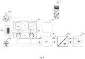
- Fig. 1 illustrates an emergency lighting system 1 according to an embodiment of the present disclosure.
- the emergency lighting system 1 comprises energy storage means 101 and an emergency lighting driver 105.
- the emergency lighting system 1 may further comprise lighting means 106 connectable to the emergency lighting system 1.
- the emergency lighting driver 105 may be an AC/DC converter, for example being able to operate the lighting means either from AC or DC supply.
- the energy storage means 101 may comprise a modular energy storage means 101.
- This may provide a higher degree of reliability (i.e., structural redundancy), and may enable taking advantage of scalability instead of using 12V lead (Pb) acid batteries in series even when not using a PV system.
- the energy storage means 101 may be located remotely from the emergency lighting driver 105; may comprise a rechargeable battery, and may in particular comprise a solar battery.
- This may enable linking up with energy storage means 101 already installed in a building, provide a higher degree of self-sufficiency, as self-produced energy is used, and provide an environmentally friendly EL system powered by solar power.
- Such energy storage means 101 are typically not discharged to SOC values close to 0%, but operated above an SOC threshold ranging between about 10% and 30% in order to maximize a service life of the energy storage means 101.
- SOC threshold ranging between about 10% and 30% in order to maximize a service life of the energy storage means 101.
- a charge below the SOC threshold is typically more than sufficient for emergency lighting.
- the SOC threshold 104 may comprise an SOC of 10%, preferably 20%, and more preferably 30%. The higher the applicable SOC threshold 104, the more capacity may be reserved for emergency response.
- the emergency lighting system 1 is operable under non-emergency (i.e., normal) conditions as well as under emergency conditions, which may comprise a failure of the power grid 103, in particular.
- the energy storage means 101 is operable above the SOC threshold 104.
- the energy storage means 101 may be chargeable by the power grid 103 in response to a price of grid supply below a threshold.
- a price threshold of 0,- € charging may take place in response to a negative price of grid supply, for example.
- charging may occur in response to a low price of grid supply.
- the energy storage means 101 may further be dischargeable to the power grid 103 in response to a peak load signaled by the power grid 103, for example.
- the emergency lighting system 1 may be operable to drive the lighting means 106 (such as LED luminaires, or other loads) off the energy storage means 101, using the charge above the SOC threshold 104.
- the lighting means 106 can as well be operated directly off the power grid 103.
- One main task of the emergency lighting system 1 is therefore to decide whether the loads are operated directly from the power grid 103 or from the connected energy storage means 101. It therefore may comprise a load switch 108 to select the appropriate supply 101, 103.
- the emergency lighting driver 105 is operable to drive the lighting means 106 (depicted on a right portion of Fig. 1 ) off the energy storage means 101, using a charge below the SOC threshold 104 reserved for emergency response.
- the emergency lighting driver 105 may be operable to drive the lighting means 106 for a period in excess of a multiple of a legally required emergency service time in dependence of the SOC of the energy storage means 101.
- the emergency lighting system 1 may further comprise a battery management unit 107 (depicted on a top-left portion of Fig. 1 ) of and connectable to the energy storage means 101.
- the emergency lighting system 1 may be configured to communicate with this battery management unit 107 so as to establish the SOC threshold 104, an SOC and/or a testing status of the energy storage means 101.
- PV and EL system may share its capacity by reserving a fraction thereof for emergency response.
- Such a communication on status and legally required testing may be mandated by a logical and/or spatial separation of the EL system 1 and the battery management 107.
- the battery management 107 may manage the energy storage means 101 and reserve the capacity needed for emergency response, while the EL system 1 may manage the lighting means 106 and perform the required testing and documentation.
- the emergency lighting system 1 may further comprise a control unit 109 for the emergency lighting system 1.
- the control unit 109 may be designed for implementing a method 2 according to a second aspect of the present disclosure or any of its embodiments, which will be explained next.
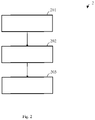
- Fig. 2 illustrates a method 2 of operating an emergency lighting system 1 comprising energy storage means 101 according to an embodiment of the present disclosure.
- the method 2 comprises basic steps of charging 201, operating 202 and driving 203.
- Step 201 involves charging the energy storage means 101 by a photovoltaic system 102 and/or a power grid 103 connectable to the emergency lighting system 1.
- Step 202 involves operating the energy storage means 101 above a state of charge SOC under non-emergency conditions.
- Step 203 involves driving lighting means 106 connectable to the emergency lighting system 1 off the energy storage means 101 in response to emergency conditions, using a charge below the SOC reserved for emergency response.
- the method 2 may be performed by an emergency lighting system 1 according to a first aspect of the present disclosure or any of its embodiments.
Priority Applications (3)
| Application Number | Priority Date | Filing Date | Title |
|---|---|---|---|
| EP20215864.8A EP4016785A1 (de) | 2020-12-21 | 2020-12-21 | Notbeleuchtungssystem einer zentralbatterie |
| CN202180079706.XA CN116601846A (zh) | 2020-12-21 | 2021-12-15 | 中央电池应急照明系统 |
| PCT/EP2021/085940 WO2022136058A1 (en) | 2020-12-21 | 2021-12-15 | Central battery emergency lighting system |
Applications Claiming Priority (1)
| Application Number | Priority Date | Filing Date | Title |
|---|---|---|---|
| EP20215864.8A EP4016785A1 (de) | 2020-12-21 | 2020-12-21 | Notbeleuchtungssystem einer zentralbatterie |
Publications (1)
| Publication Number | Publication Date |
|---|---|
| EP4016785A1 true EP4016785A1 (de) | 2022-06-22 |
Family
ID=73856046
Family Applications (1)
| Application Number | Title | Priority Date | Filing Date |
|---|---|---|---|
| EP20215864.8A Pending EP4016785A1 (de) | 2020-12-21 | 2020-12-21 | Notbeleuchtungssystem einer zentralbatterie |
Country Status (3)
| Country | Link |
|---|---|
| EP (1) | EP4016785A1 (de) |
| CN (1) | CN116601846A (de) |
| WO (1) | WO2022136058A1 (de) |
Citations (5)
| Publication number | Priority date | Publication date | Assignee | Title |
|---|---|---|---|---|
| KR20000015790A (ko) * | 1997-03-19 | 2000-03-15 | 넥스텍 파워 시스템즈, 인코포레이티드 | 고효율 조명을 위한 전력 시스템 |
| WO2010057138A2 (en) * | 2008-11-14 | 2010-05-20 | Inovus Solar, Inc. | Energy-efficient solar-powered outdoor lighting |
| EP2437374A2 (de) * | 2010-10-01 | 2012-04-04 | Birchcroft Plc. | Gleichstrom-Beleuchtungssystem |
| US20180054070A1 (en) * | 2016-08-16 | 2018-02-22 | Helion Concepts,Inc. | Hardware/software reconfigurable, intelligent and versatile electrical energy provisioning system for on-grid and off-grid applications |
| CN111404186A (zh) * | 2020-05-11 | 2020-07-10 | 国网湖南省电力有限公司 | 一种配变动态增容智能储能装置及控制方法 |
-
2020
- 2020-12-21 EP EP20215864.8A patent/EP4016785A1/de active Pending
-
2021
- 2021-12-15 CN CN202180079706.XA patent/CN116601846A/zh active Pending
- 2021-12-15 WO PCT/EP2021/085940 patent/WO2022136058A1/en active Application Filing
Patent Citations (5)
| Publication number | Priority date | Publication date | Assignee | Title |
|---|---|---|---|---|
| KR20000015790A (ko) * | 1997-03-19 | 2000-03-15 | 넥스텍 파워 시스템즈, 인코포레이티드 | 고효율 조명을 위한 전력 시스템 |
| WO2010057138A2 (en) * | 2008-11-14 | 2010-05-20 | Inovus Solar, Inc. | Energy-efficient solar-powered outdoor lighting |
| EP2437374A2 (de) * | 2010-10-01 | 2012-04-04 | Birchcroft Plc. | Gleichstrom-Beleuchtungssystem |
| US20180054070A1 (en) * | 2016-08-16 | 2018-02-22 | Helion Concepts,Inc. | Hardware/software reconfigurable, intelligent and versatile electrical energy provisioning system for on-grid and off-grid applications |
| CN111404186A (zh) * | 2020-05-11 | 2020-07-10 | 国网湖南省电力有限公司 | 一种配变动态增容智能储能装置及控制方法 |
Also Published As
| Publication number | Publication date |
|---|---|
| CN116601846A (zh) | 2023-08-15 |
| WO2022136058A1 (en) | 2022-06-30 |
Similar Documents
| Publication | Publication Date | Title |
|---|---|---|
| US6795322B2 (en) | Power supply with uninterruptible function | |
| EP4084262A1 (de) | Ladesystem für wechselstation oder energiespeicherstation | |
| US20110304298A1 (en) | Battery charging using multiple chargers | |
| WO2010082506A1 (ja) | 直流給電システム | |
| CN111756065A (zh) | 一种混合供电储能系统 | |
| KR102019087B1 (ko) | 태양광 발전 에너지 저장시스템의 제어방법 | |
| US20200366101A1 (en) | Energy storage system | |
| JP6800353B2 (ja) | 照明電源システム及び方法 | |
| CN101917043A (zh) | 锂离子蓄电池充放电控制电路 | |
| KR20180090673A (ko) | 하이브리드 에너지 저장 시스템 | |
| KR20170026695A (ko) | 하이브리드 에너지저장 시스템 | |
| JPH10336916A (ja) | 非常用電源システム | |
| EP4016785A1 (de) | Notbeleuchtungssystem einer zentralbatterie | |
| JP2001177995A (ja) | ハイブリッド電源システム | |
| KR102257906B1 (ko) | 에너지 저장 시스템 | |
| KR101215396B1 (ko) | 방전전류제어를 이용한 하이브리드 스마트그리드 무정전전원장치 | |
| CN111095717A (zh) | 储能系统 | |
| US20160276850A1 (en) | Charging Bus | |
| CN105634110A (zh) | 一种远程在线式工业ups监测系统 | |
| KR101742796B1 (ko) | 직류 고전압 대용량 무접점 스위칭 장치를 이용한 이차 전지 충방전 전원 장치 | |
| CN218735088U (zh) | 多模式充电应急灯电路及照明设备 | |
| CN111406352B (zh) | 储能系统 | |
| JP3201595U (ja) | 電源装置 | |
| KR20190067726A (ko) | 에너지 저장부를 포함하는 무정전 전원장치 및 그 구동방법 | |
| US20230307946A1 (en) | Battery for an emergency lighting unit |
Legal Events
| Date | Code | Title | Description |
|---|---|---|---|
| PUAI | Public reference made under article 153(3) epc to a published international application that has entered the european phase |
Free format text: ORIGINAL CODE: 0009012 |
|
| STAA | Information on the status of an ep patent application or granted ep patent |
Free format text: STATUS: THE APPLICATION HAS BEEN PUBLISHED |
|
| AK | Designated contracting states |
Kind code of ref document: A1 Designated state(s): AL AT BE BG CH CY CZ DE DK EE ES FI FR GB GR HR HU IE IS IT LI LT LU LV MC MK MT NL NO PL PT RO RS SE SI SK SM TR |
|
| STAA | Information on the status of an ep patent application or granted ep patent |
Free format text: STATUS: REQUEST FOR EXAMINATION WAS MADE |
|
| 17P | Request for examination filed |
Effective date: 20221208 |
|
| RBV | Designated contracting states (corrected) |
Designated state(s): AL AT BE BG CH CY CZ DE DK EE ES FI FR GB GR HR HU IE IS IT LI LT LU LV MC MK MT NL NO PL PT RO RS SE SI SK SM TR |