EP4016493B1 - Verfahren und vorrichtung zur übertragung von optischen signalen mit temperatur- und alterungsangepasster mittlerer leistung, entsprechendes computerprogramm und entsprechender programmsupport - Google Patents
Verfahren und vorrichtung zur übertragung von optischen signalen mit temperatur- und alterungsangepasster mittlerer leistung, entsprechendes computerprogramm und entsprechender programmsupport Download PDFInfo
- Publication number
- EP4016493B1 EP4016493B1 EP21212397.0A EP21212397A EP4016493B1 EP 4016493 B1 EP4016493 B1 EP 4016493B1 EP 21212397 A EP21212397 A EP 21212397A EP 4016493 B1 EP4016493 B1 EP 4016493B1
- Authority
- EP
- European Patent Office
- Prior art keywords
- reduced
- temperature
- mode
- setpoint
- laser diode
- Prior art date
- Legal status (The legal status is an assumption and is not a legal conclusion. Google has not performed a legal analysis and makes no representation as to the accuracy of the status listed.)
- Active
Links
Images


Classifications
-
- H—ELECTRICITY
- H04—ELECTRIC COMMUNICATION TECHNIQUE
- H04B—TRANSMISSION
- H04B10/00—Transmission systems employing electromagnetic waves other than radio-waves, e.g. infrared, visible or ultraviolet light, or employing corpuscular radiation, e.g. quantum communication
- H04B10/07—Arrangements for monitoring or testing transmission systems; Arrangements for fault measurement of transmission systems
- H04B10/075—Arrangements for monitoring or testing transmission systems; Arrangements for fault measurement of transmission systems using an in-service signal
- H04B10/079—Arrangements for monitoring or testing transmission systems; Arrangements for fault measurement of transmission systems using an in-service signal using measurements of the data signal
- H04B10/0795—Performance monitoring; Measurement of transmission parameters
- H04B10/07955—Monitoring or measuring power
-
- H—ELECTRICITY
- H01—ELECTRIC ELEMENTS
- H01S—DEVICES USING THE PROCESS OF LIGHT AMPLIFICATION BY STIMULATED EMISSION OF RADIATION [LASER] TO AMPLIFY OR GENERATE LIGHT; DEVICES USING STIMULATED EMISSION OF ELECTROMAGNETIC RADIATION IN WAVE RANGES OTHER THAN OPTICAL
- H01S5/00—Semiconductor lasers
- H01S5/04—Processes or apparatus for excitation, e.g. pumping, e.g. by electron beams
- H01S5/042—Electrical excitation ; Circuits therefor
- H01S5/0428—Electrical excitation ; Circuits therefor for applying pulses to the laser
-
- H—ELECTRICITY
- H04—ELECTRIC COMMUNICATION TECHNIQUE
- H04B—TRANSMISSION
- H04B10/00—Transmission systems employing electromagnetic waves other than radio-waves, e.g. infrared, visible or ultraviolet light, or employing corpuscular radiation, e.g. quantum communication
- H04B10/50—Transmitters
- H04B10/501—Structural aspects
- H04B10/503—Laser transmitters
-
- H—ELECTRICITY
- H01—ELECTRIC ELEMENTS
- H01S—DEVICES USING THE PROCESS OF LIGHT AMPLIFICATION BY STIMULATED EMISSION OF RADIATION [LASER] TO AMPLIFY OR GENERATE LIGHT; DEVICES USING STIMULATED EMISSION OF ELECTROMAGNETIC RADIATION IN WAVE RANGES OTHER THAN OPTICAL
- H01S5/00—Semiconductor lasers
- H01S5/06—Arrangements for controlling the laser output parameters, e.g. by operating on the active medium
- H01S5/068—Stabilisation of laser output parameters
- H01S5/06804—Stabilisation of laser output parameters by monitoring an external parameter, e.g. temperature
-
- H—ELECTRICITY
- H01—ELECTRIC ELEMENTS
- H01S—DEVICES USING THE PROCESS OF LIGHT AMPLIFICATION BY STIMULATED EMISSION OF RADIATION [LASER] TO AMPLIFY OR GENERATE LIGHT; DEVICES USING STIMULATED EMISSION OF ELECTROMAGNETIC RADIATION IN WAVE RANGES OTHER THAN OPTICAL
- H01S5/00—Semiconductor lasers
- H01S5/06—Arrangements for controlling the laser output parameters, e.g. by operating on the active medium
- H01S5/068—Stabilisation of laser output parameters
- H01S5/0683—Stabilisation of laser output parameters by monitoring the optical output parameters
- H01S5/06835—Stabilising during pulse modulation or generation
-
- H—ELECTRICITY
- H04—ELECTRIC COMMUNICATION TECHNIQUE
- H04B—TRANSMISSION
- H04B10/00—Transmission systems employing electromagnetic waves other than radio-waves, e.g. infrared, visible or ultraviolet light, or employing corpuscular radiation, e.g. quantum communication
- H04B10/50—Transmitters
- H04B10/564—Power control
-
- H—ELECTRICITY
- H01—ELECTRIC ELEMENTS
- H01S—DEVICES USING THE PROCESS OF LIGHT AMPLIFICATION BY STIMULATED EMISSION OF RADIATION [LASER] TO AMPLIFY OR GENERATE LIGHT; DEVICES USING STIMULATED EMISSION OF ELECTROMAGNETIC RADIATION IN WAVE RANGES OTHER THAN OPTICAL
- H01S5/00—Semiconductor lasers
- H01S5/06—Arrangements for controlling the laser output parameters, e.g. by operating on the active medium
- H01S5/0617—Arrangements for controlling the laser output parameters, e.g. by operating on the active medium using memorised or pre-programmed laser characteristics
-
- H—ELECTRICITY
- H01—ELECTRIC ELEMENTS
- H01S—DEVICES USING THE PROCESS OF LIGHT AMPLIFICATION BY STIMULATED EMISSION OF RADIATION [LASER] TO AMPLIFY OR GENERATE LIGHT; DEVICES USING STIMULATED EMISSION OF ELECTROMAGNETIC RADIATION IN WAVE RANGES OTHER THAN OPTICAL
- H01S5/00—Semiconductor lasers
- H01S5/06—Arrangements for controlling the laser output parameters, e.g. by operating on the active medium
- H01S5/068—Stabilisation of laser output parameters
- H01S5/06808—Stabilisation of laser output parameters by monitoring the electrical laser parameters, e.g. voltage or current
Definitions
- the present invention relates to the transmission of data and more particularly to the transmission of data by optical signals.
- An optical signal communication system generally includes an optical signal transmitting device, an optical signal receiving device, and an optical fiber extending between the transmitting device and the receiving device.
- the transmission device generally comprises a laser diode and an amplifier component driving the laser diode in current so as to modulate the laser signal as a function of a digital signal coming from a processor in charge of bringing the data to be transmitted into conformity with the communication protocol used for transmission.
- the optical signal emitted by the transmission device in the optical fiber comprises a succession of power levels as a function of time which form symbols whose numerical value depends on the instantaneous power drawn off by the reception device at the time center of each symbol. received.
- a laser diode produces a power beam when the laser diode is subjected to an excitation current with an intensity greater than a laser threshold (Ith).
- Ith a laser threshold
- the power P out of the laser beam produced by a laser diode supplied by an electric excitation current having an intensity I Drive is represented.
- the laser diode produces a beam whose power P out increases almost linearly with the intensity of the excitation current from the laser threshold to at a point of inflection called "rollover" beyond which the power decreases despite the increase in the intensity of the excitation current.
- the efficiency (SE) of the laser diode is the slope of the linear part of the power curve as a function of the intensity of the excitation current.
- a laser beam must have an average power P avg included in a predefined range and a sufficiently large extinction rate ER. .
- the extinction rate is 10 log P 1 P 0 and is therefore representative of the ratio between the light power P1, relatively strong, corresponding to logic level 1 and the light power P0, relatively weak, corresponding to logic level 0: the difference between the powers P1 and P0 on transmission must be sufficiently large to ensure that logic level 1 can be distinguished from logic level 0 in the optical signal received by the receiving device.
- the average power P avg is the average of the powers of the signals transmitted and can be approximated by calculating the average between the powers P1 and P0.
- There figure 2 represents the power P out of the optical signal as a function of the intensity I Drive of the excitation current and makes correspond to the power P1 an intensity I1 of the excitation current and to the power P0 an intensity I0 of the excitation current.
- the first management mode defines a control constraint as a function of the temperature.
- the temperature of the diode is measured periodically and the value of the intensity of the excitation current to be applied is sought in a model.
- This mode of control is relatively simple and makes it possible to predefine intensity levels of the excitation current according to the temperature taking into account, on the one hand, the capacity of the amplifier to supply currents of high intensity. and, on the other hand, rollovers. On the other hand, this does not take into account the aging of the laser diode nor the differences existing between the laser diode used and those having been used for the modelling.
- the control electronics comprises a photodiode placed in the vicinity of the laser diode to measure parasitic radiation from the laser diode.
- This parasitic radiation has a power proportional to the power of the beam at the output of the laser diode and the photodiode is chosen of the PIN type so that the current which crosses it is independent of the temperature so that there is a linear relationship between the current crossing the photodiode and the power of the beam at the output of the laser diode.
- the setpoint values are fixed and have been determined by successive iterations for each emission device during a calibration step carried out in the factory. The performance of this control depends on the properties of the photodiode.
- the operating limits of this type of control also depend on non-linearities such as the capacity of the amplifier to produce an excitation current corresponding to the desired power of the beam and the variation of the rollover point of the laser diode used as a function of his aging.
- non-linearities such as the capacity of the amplifier to produce an excitation current corresponding to the desired power of the beam and the variation of the rollover point of the laser diode used as a function of his aging.
- this does not make it possible to maximize the signal-to-noise ratio.
- the object of the invention is in particular to propose a control of the laser diode allowing the production of a laser beam whose average power is as high as possible throughout its operating range.
- the setpoint values are chosen to allow the most efficient signal transmission possible by operating the laser diode at optimum power (determined for example to be the highest possible for a predetermined lifetime of the laser diode).
- optimum power determined for example to be the highest possible for a predetermined lifetime of the laser diode.
- the invention also relates to a device for emitting a laser beam for the transmission of data, comprising an electronic processing circuit for creating a current signal representative of data to be transmitted, an amplifier receiving the current signal as input and supplying at the output an excitation current of a laser diode, a driver circuit of the amplifier having a first input receiving setpoint values and a second input connected to a photodiode which is placed in the vicinity of the laser diode to supply the circuit for driving a current representative of a power of the laser beam, a temperature probe connected to the processing circuit to supply a temperature signal in the vicinity of the laser diode; the processing circuit being arranged to implement the transmission method of the invention.
- the invention also relates to a computer program for implementing this method and a data medium containing such a program.
- the device for emitting a laser beam for the transmission of data comprises an electronic processing circuit 1 connected via a control interface 2 to a laser diode 3.
- the diode model laser does not matter, but the use of the component referenced EBS63432-B1634 produced by the company EZCONN can for example be envisaged.
- the processing circuit 1 here comprises a processor and a memory containing computer programs that can be executed by the processor.
- One of these programs is arranged in a manner known per se to ensure the formatting of data to be transmitted according to a predefined protocol and the generation of the current signal representative of the data to be transmitted in the format considered.
- the control interface 2 comprises an amplifier 4 having an input connected to the processing circuit 1 to receive the current signal representative of the logic level to be transmitted and an output connected to the laser diode 3 to which the amplifier 4 supplies a current d 'excitement.
- the control interface 2 comprises a temperature probe 8 placed in the vicinity of the laser diode 3 and connected to the processing circuit 1 to supply it with a temperature signal representative of the temperature in the vicinity of the laser diode 3.
- the control interface 2 comprises a device 9 for measuring the excitation current I0/I1 placed between the amplifier 4 and the laser diode 3 and connected to the processing circuit 1.
- the control interface 2 is for example that referenced M02099 produced by the company MACOM allowing the establishment of a communication environment called G-PON (from the English “Gigabit capable Passive Optical Network” or passive optical network with gigabit).
- the transmission is ensured by modulating the excitation current of the laser diode 3 according to two current intensities associated with the logic levels 0 and 1 to be transmitted.
- One of the programs of the processing unit thus comprises instructions arranged to implement a transmission method comprising the step of controlling an excitation current of the laser diode 3 by slaving the excitation current to a power of the laser beam produced by the laser diode 3 and by modulating the excitation current as a function of the data to be transmitted in order to encode these data with power levels of the laser beam.
- the amplifiers such as the amplifier 4 have variable characteristics from one individual to another; similarly, analog/digital converters and digital/analog converters have characteristics that vary from one individual to another; the first input of the servo circuit provides a digital value; the second input of the servo circuit also provides a digital value from an analog/digital converter.
- the nominal lower setpoint value L 0_A and the nominal upper setpoint value L 1_A are stored in the memory of the processing circuit 1. They were defined during a calibration step to obtain a target average power P AVG target corresponding to a percentage of the maximum average power P AVG max that the laser diode 3 is capable of supplying, for example 70% (see the figure 4 And 6 ) and to obtain the desired minimum extinction rate, namely 10 dB.
- the calibration step is known in itself: it is carried out in the factory, by successive iterations, and consists of setting setpoint values and letting the servo-control operate until it converges and reaches a point of 'balance.
- the setpoint values adopted are those which made it possible, after convergence, to obtain the desired properties of the laser beam.
- the nominal setpoint values L 0_A and L 1_A are chosen according to the known characteristics of the transmission device.
- a calibration phase is carried out on a reference emission device in order to determine the nominal setpoint values L 0_A and L 1_A for other emission devices.
- the nominal setpoint values L 0_A and L 1_A are chosen as a function of the characteristics of certain constituent elements of the transmission device.
- the lower reduced setpoint value L 0_B and the upper reduced setpoint value L 1_B are fixed values.
- the lower reduced setpoint value L 0_B and the upper reduced setpoint value L 1_B are determined experimentally from tests carried out on a sample of devices for transmitting signals by allowing the degraded operating mode of each transmission device to converge towards a reduced upper value resulting from convergence and a reduced lower value resulting from convergence.
- the lower reduced setpoint value L 0_B and the upper reduced setpoint value L 1_B are determined by calculation from respectively the lower nominal setpoint value L 0_A and the upper nominal setpoint value L 1_A .
- the lower reduced setpoint value L 0_B and the upper reduced setpoint value L 1_B are determined by applying, respectively to the lower nominal setpoint value L 0_A and to the upper nominal setpoint value L 1_A , a depreciation advantageously comprised between 30% and 40%, preferably 37% to lower the average transmitted power by about 2 dB while maintaining substantially the same rate of extinction.
- a depreciation advantageously comprised between 30% and 40%, preferably 37% to lower the average transmitted power by about 2 dB while maintaining substantially the same rate of extinction.
- the average power of the beam is greater than the minimum average power sufficiently to allow an extinction rate greater than 10 dB to be obtained in the present example.
- the average power retained to correspond to the lower level is advantageously determined to be greater than the minimum average power so as to allow better reception. Thanks to the reduced setpoint values, this reduced average power can be reached without using an intensity greater than that corresponding to the inflection point of the power curve (hatched on the figure 4 the entire zone, known as the rollover zone, corresponding to unattainable powers, despite the increase in the excitation current, due to the inflection of the power curve).
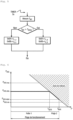
- the first temperature threshold T THRESHOLD is located opposite the intersection between the target average power curve P AVG target in nominal operating mode and the limit of the rollover zone.
- the lower reduced setpoint value L 0_B and the upper reduced setpoint value L 1_B are stored in the memory of the processing circuit 1.
- the processing circuit 1 acquires every 5 seconds the measurement of temperature T INT and compares it with the first temperature threshold T THRESHOLD .
- the processing circuit 1 triggers the nominal mode by writing the lower nominal setpoint value L 0_A and the upper nominal setpoint value L 1_A in registers of the memory 6 (for example, respectively the register at address 0x9A and the register at address 0x9B of memory 6 of component MACOM M02099) where servo circuit 5 will look for them to drive amplifier 4 so as to slave the excitation current between these two values as a function of the signal I MON representative of the power of the laser beam.
- the processing circuit 1 triggers the degraded operating mode by writing the lower reduced setpoint value L 0_B and the upper reduced setpoint value L 1_B in the registers of the memory 6 (for example the registers at addresses 0x9A and 0x9B) where the servo circuit 5 fetches them to control the amplifier 4 so as to slave the excitation current between these two values as a function of the signal I MON representative of the power of the laser beam.
- the processing circuit 1 switches from the nominal operating mode to the degraded operating mode when the temperature T INT in the vicinity of the laser diode 3 exceeds the first temperature threshold T THRESHOLD by a predetermined overrun value and switches from the degraded operating mode to the nominal operating mode when the temperature T INT in the vicinity of the laser diode 3 falls below the first temperature threshold T THRESHOLD decreased by a predetermined return value.
- the overshoot value and the return value are here equal to 3°C.
- a second temperature threshold T MAX or limit threshold, greater than the first temperature threshold T THRESHOLD .
- the second temperature threshold T MAX is located opposite the intersection between the reduced average power curve P AVG reduced in degraded operating mode and the limit of the rollover zone.
- the processing circuit 1 compares the temperature measurement T INT and the second temperature threshold T MAX every 5 seconds. If the temperature measurement T INT exceeds the second temperature threshold T MAX , the processing circuit 1 cuts off the power supply to the amplifier 4 so that the laser diode 3 is no longer powered allowing it to cool and avoiding premature aging . The processing circuit 1 can then send an alert sending back an error message to the unit transmitting the data connected to the processing circuit 1.
- the average power curve has a downward slope at the level of the temperature range corresponding to the degraded operating mode (range 2 on the figure 5 ). This downward slope coincides with the limit of the rollover zone between the temperature thresholds T THRESHOLD and T MAX .
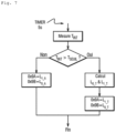
- FIG. 7 Operation is illustrated in the figure 7 : it is identical to that of the first mode of implementation except in that the processing circuit 1 must calculate the reduced lower setpoint value L 0_T used for the servo-control and the reduced upper setpoint value L 1_T used for the enslavement just before writing them into memory 6 to initiate the degraded operating mode.
- all or part of the embodiments can easily be adapted to cover other communication protocols, such as those named E-PON, XGS-PON, 10GEPON, etc. or even other models of control components from from MACOM or other companies such as SEMTECH or UXFASTIC.
- NRZ modulation is used according to which the launched optical signal takes two powers depending on whether it carries a 0 or a 1 is generally used. It therefore allows the transport of one bit per time symbol is well suited to data rates up to 25 Gbits/s. However, other modulations can be used for these same bit rates or others. For example, beyond 25 Gbits/s, PAM4 modulation will be used, which allows the transport of two bits per symbol time, the optical signal launched taking four powers depending on whether it carries a symbol 00, 01, 10 or 11. More generally, in certain embodiments, it is possible to use any communication protocol based on a transmission technique with several logical levels, such as for example the derivatives of pulse amplitude modulation (PAM for English "Pulse-amplitude modulation PAM").
- PAM4 modulation the derivatives of pulse amplitude modulation
- the transmission of a logic level 0 is established by launching into the optical fiber a light signal of low power (a few hundred ⁇ W) and the transmission of a logic level 1 is established by launching into the fiber a higher power light signal (a few mW).
- a light signal of low power a few hundred ⁇ W
- a logic level 1 is established by launching into the fiber a higher power light signal (a few mW).
- the reverse can be expected.
- the reduced setpoint values L 0_B , L 1_B can be determined by successive iterations during a calibration phase.
- the temperature T INT in the vicinity of the laser diode is determined according to a predetermined period and the reduced setpoint values L 0_B , L 1_B are calculated according to this period.
- the laser diode is controlled to have, in the third operating mode (the temperature exceeds the second predetermined temperature threshold T MAX ), an even more limited operation than in the second operating mode.
- the temperature measurement period can be less or more than 5 seconds.
- the temperature thresholds, overshoot value and return value may be different from those described.
- the second temperature threshold is optional.
- the structure of the device may be different.
- the temperature sensor may be outside the control interface 2.
- the measuring member 9 is optional.
Landscapes
- Physics & Mathematics (AREA)
- Electromagnetism (AREA)
- Engineering & Computer Science (AREA)
- Computer Networks & Wireless Communication (AREA)
- Signal Processing (AREA)
- Optics & Photonics (AREA)
- Condensed Matter Physics & Semiconductors (AREA)
- General Physics & Mathematics (AREA)
- Semiconductor Lasers (AREA)
- Optical Communication System (AREA)
Claims (14)
- Datenübertragungsverfahren, umfassend den Schritt des Steuerns eines Anregungsstroms für eine Laserdiode einer Laserstrahl-Emissionsvorrichtung, indem der Anregungsstrom auf eine Leistung des Laserstrahls geregelt wird und indem der Anregungsstrom in Abhängigkeit der zu übertragenden Daten moduliert wird, um diese Daten mit Laserstrahlleistungsniveaus zu kodieren, dadurch gekennzeichnet, dass das Übertragungsverfahren den Schritt des Messens einer Temperatur (TINT) in der Nähe der Laserdiode umfasst, um auszuführen:- einen ersten Betriebsmodus bis zu einem ersten vorbestimmten Temperaturschwellenwert (TSEUIL), in dem der Anregungsstrom geregelt wird, indem ein nominaler unterer Sollwert (L0_A) und ein nominaler oberer Sollwert (L1_A), die einem unteren Leistungsniveau bzw. einem oberen Leistungsniveau entsprechen, derart verwendet werden, dass der Strahl eine durchschnittliche Leistung und ein Extinktionsverhältnis hat, die optimal für die Übertragung der Daten sind;- einen zweiten Betriebsmodus, wenn die Temperatur den ersten Temperaturschwellenwert überschreitet, in dem der Anregungsstrom auf einen reduzierten unteren Sollwert (L0_B; L0_T) und einen reduzierten oberen Sollwert (L1_B; L1_T) geregelt wird, die dem unteren Leistungsniveau bzw. dem oberen Leistungsniveau entsprechen, derart, dass der Strahl eine reduzierte durchschnittliche Leistung hat, während ein Extinktionsverhältnis, das für die Übertragung der Daten akzeptabel ist, beibehalten wird.
- Verfahren nach Anspruch 1, bei dem die reduzierten Sollwerte (L0_B, L1_B) durch aufeinanderfolge Iterationen während einer Kalibrierungsphase bestimmt werden.
- Verfahren nach Anspruch 1, bei dem die reduzierten Sollwerte (L0_B, L1_B) durch Berechnung auf der Basis der nominalen Sollwerte (L0_A, L1_A) bestimmt werden.
- Verfahren nach Anspruch 1, bei dem die reduzierten Sollwerte (L0_T, L1_T) durch Berechnung während des Betriebs der Emissionsvorrichtung bestimmt werden und die Berechnung eine lineare Interpolation anhand von nominalen Sollwerten (L0_A, L1_A), der bestimmten Temperatur (TINT) und des ersten Betriebstemperaturschwellenwerts (TSEUIL) ist.
- Verfahren nach Anspruch 4, bei dem die lineare Interpolation ebenso auf reduzierte theoretische Sollwerte (L0_B, L1_B) basiert wird, für einen zweiten Betriebstemperaturschwellenwert (TMAX), derart dass:- der reduzierte untere Sollwert L0_T, der für die Regelung verwendet wird, gleich ist mit:
 - der reduzierte obere Sollwert L1_T, der für die Regelung verwendet wird, gleich ist mit:
- Verfahren nach einem der Ansprüche 3 bis 5, bei dem die Temperatur (TINT) in der Nähe der Laserdiode gemäß einer vorbestimmten Periode bestimmt wird und die reduzierten Sollwerte (L0_B, L1_B) gemäß dieser Periode berechnet werden.
- Verfahren nach Anspruch 1, bei dem die reduzierten Sollwerte experimentell anhand von Versuchen bestimmt werden, die an einer Probe von Signalemissionsvorrichtungen ausgeführt werden, indem ermöglicht wird, dass der herabgesetzte Betriebsmodus jeder Emissionsvorrichtung auf einen reduzierten oberen Wert und einen reduzierten unteren Wert, die aus der Konvergenz resultieren, konvergiert.
- Verfahren nach Anspruch 7, bei dem die reduzierten Sollwerte im Wesentlichen gleich einem der folgenden Werte sind:- ein Durchschnitt der reduzierten oberen Werte, die aus der Konvergenz resultieren, und ein Durchschnitt der reduzierten unteren Werte, die aus der Konvergenz resultieren;- ein Mindestwert der reduzierten oberen Werte, die aus der Konvergenz resultieren, und ein Mindestwert der reduzierten unteren Werte, die aus der Konvergenz resultieren;- ein fünfundzwanzigstes Perzentil der reduzierten oberen Werte, die aus der Konvergenz resultieren, und ein fünfundzwanzigstes Perzentil der reduzierten unteren Werte, die aus der Konvergenz resultieren.
- Verfahren nach einem der vorhergehenden Ansprüche, bei dem ein dritter Betriebsmodus umgesetzt wird, wenn die Temperatur einen zweiten vorbestimmten Temperaturschwellenwert (TMAX) überschreitet.
- Verfahren nach Anspruch 9, bei dem die Laserdiode gesteuert wird, um in dem dritten Betriebsmodus einen noch begrenzteren Betrieb als im zweiten Betriebsmodus zu haben.
- Verfahren nach einem der vorhergehenden Ansprüche, bei dem das Verfahren vom nominalen Betriebsmodus in den herabgesetzten Betriebsmodus übergeht, wenn die Temperatur in der Nähe der Laserdiode den ersten Temperaturschwellenwert um einen vorbestimmten Überschreitungswert überschreitet, und von dem herabgesetzten Betriebsmodus in den nominalen Betriebsmodus übergeht, wenn die Temperatur in der Nähe der Laserdiode unter den ersten Temperaturschwellenwert fällt, der um einen vorbestimmten Rückgabewert verringert ist.
- Laserstrahl-Emissionsvorrichtung für die Übertragung von Daten, umfassend eine elektronische Verarbeitungsschaltung (1) zum Erzeugen eines Stromsignals, das repräsentativ für zu übertragenden Daten ist, einen Verstärker (4), der am Eingang das Stromsignal empfängt und am Ausgang einen Anregungsstrom zur Anregung einer Laserdiode (3) liefert, eine Steuerschaltung (5) zum Steuern des Verstärkers, die einen ersten Eingang hat, der Sollwerte empfängt, und einen zweiten Eingang, der mit einer Photodiode (7) verbunden ist, die in der Nähe der Laserdiode (3) platziert ist, um der Steuerschaltung (5) einen Strom zu liefern, der repräsentativ für eine Leistung des Laserstrahls ist, eine Temperatursonde (8), die mit der Verarbeitungsschaltung (1) verbunden ist, um ein Signal der Temperatur in der Nähe der Laserdiode (3) zu liefern; wobei die Verarbeitungsschaltung (1) ausgebildet ist, ein Übertragungsverfahren durchzuführen, das den Schritt des Messens einer Temperatur (TINT) umfasst, um umzusetzen:- einen ersten Betriebsmodus bis zu einem ersten vorbestimmten Temperaturschwellenwert (TSEUIL), in dem der Anregungsstrom geregelt wird, indem ein nominaler unterer Sollwert (L0_A) und ein nominaler oberer Sollwert (L1_A), die einem unteren Leistungsniveau bzw. einem oberen Leistungsniveau entsprechen, verwendet werden, derart, dass der Strahl eine durchschnittliche Leistung und ein Extinktionsverhältnis hat, die optimal für die Übertragung der Daten sind;- einen zweiten Betriebsmodus, wenn die Temperatur den ersten Temperaturschwellenwert überschreitet, in dem der Anregungsstrom auf einen reduzierten unteren Sollwert (L0_B, L0_T) und einen reduzierten oberen Sollwert (L1_B; L1_T) geregelt wird, die dem unteren Leistungsniveau bzw. dem oberen Leistungsniveau entsprechen, derart, dass der Strahl eine reduzierte durchschnittliche Leistung hat, während ein Extinktionsverhältnis, das für die Übertragung der Daten akzeptabel ist, beibehalten wird.
- Computerprogramm, umfassend Anweisungen, die ausgebildet sind, ein Übertragungsverfahren nach einem der Ansprüche 1 bis 11 durchzuführen.
- Datenträger, der ein Computerprogramm enthält, das Anweisungen umfasst, die ausgebildet sind, ein Übertragungsverfahren nach einem der Ansprüche 1 bis 11 durchzuführen.
Applications Claiming Priority (1)
| Application Number | Priority Date | Filing Date | Title |
|---|---|---|---|
| FR2013734A FR3118257A1 (fr) | 2020-12-18 | 2020-12-18 | Procédé et dispositif de transmission de signaux optiques à puissance moyenne adaptée à la température et au vieillissement, programme informatique et support de programme correspondants. |
Publications (3)
| Publication Number | Publication Date |
|---|---|
| EP4016493A2 EP4016493A2 (de) | 2022-06-22 |
| EP4016493A3 EP4016493A3 (de) | 2022-07-13 |
| EP4016493B1 true EP4016493B1 (de) | 2023-07-05 |
Family
ID=75108497
Family Applications (1)
| Application Number | Title | Priority Date | Filing Date |
|---|---|---|---|
| EP21212397.0A Active EP4016493B1 (de) | 2020-12-18 | 2021-12-03 | Verfahren und vorrichtung zur übertragung von optischen signalen mit temperatur- und alterungsangepasster mittlerer leistung, entsprechendes computerprogramm und entsprechender programmsupport |
Country Status (7)
| Country | Link |
|---|---|
| US (1) | US12160263B2 (de) |
| EP (1) | EP4016493B1 (de) |
| CN (1) | CN114650099B (de) |
| AR (1) | AR124374A1 (de) |
| CA (1) | CA3140939C (de) |
| ES (1) | ES2959121T3 (de) |
| FR (1) | FR3118257A1 (de) |
Families Citing this family (2)
| Publication number | Priority date | Publication date | Assignee | Title |
|---|---|---|---|---|
| US20230111084A1 (en) * | 2021-10-12 | 2023-04-13 | Zebra Technologies Corporation | Methods and devices for an electrically efficient green laser diode drive system with boost servo |
| CN115801117B (zh) * | 2022-09-19 | 2026-03-27 | 北京遥测技术研究所 | 一种新型的激光通信收发光束一体化监视系统及监视方法 |
Family Cites Families (19)
| Publication number | Priority date | Publication date | Assignee | Title |
|---|---|---|---|---|
| US4221483A (en) * | 1978-11-20 | 1980-09-09 | Spectra-Physics, Inc. | Laser beam level instrument |
| FR2684251B1 (fr) * | 1991-11-26 | 1995-07-28 | Hutchinson | Moteur lineaire asservi a reluctance variable. |
| FR2694423B1 (fr) * | 1992-07-30 | 1994-12-23 | France Telecom | Dispositif de contrôle de la puissance de sortie des diodes laser. |
| JP3840794B2 (ja) * | 1998-04-13 | 2006-11-01 | 富士ゼロックス株式会社 | レーザ駆動装置 |
| DE10064775A1 (de) * | 2000-12-22 | 2002-06-27 | Thomson Brandt Gmbh | Verfahren und Anordnung zum Regeln der Lichtleistung eines Abtaststrahls in einem Gerät zum Lesen oder zum Beschreiben optischer Aufzeichnungsträger |
| US6862302B2 (en) * | 2002-02-12 | 2005-03-01 | Finisar Corporation | Maintaining desirable performance of optical emitters over temperature variations |
| US7166826B1 (en) * | 2002-11-13 | 2007-01-23 | Micrel, Incorporated | Automatic control of laser diode current and optical power output |
| US7433375B2 (en) * | 2003-10-09 | 2008-10-07 | National Semiconductor Corporation | Laser trim and compensation methodology for passively aligning optical transmitter |
| US7266136B2 (en) * | 2004-03-25 | 2007-09-04 | Finisar Corporation | Temperature compensation for fiber optic transceivers using optimized convergence algorithms |
| EP1594238A3 (de) * | 2004-05-06 | 2006-05-03 | Avanex Corporation | Verfahren und System zur Steuerung von Laserdioden in optischen Kommunikationssystemen |
| TWI274853B (en) * | 2005-07-06 | 2007-03-01 | Asia Optical Co Inc | A laser level and its temperature control method with warm-control equipment |
| CA2915847C (en) * | 2005-10-21 | 2019-01-08 | Stryker Corporation | System and method for recharging a battery exposed to a harsh environment |
| JP2009111259A (ja) * | 2007-10-31 | 2009-05-21 | Toshiba Corp | 半導体レーザ駆動制御装置および駆動制御方法 |
| DE102016125457A1 (de) * | 2015-12-25 | 2017-06-29 | Panasonic Intellectual Property Management Co., Ltd. | Beleuchtungslicht-Kommunikationsvorrichtung und Kommunikationsmodul |
| GB2562138B (en) * | 2018-01-12 | 2019-06-12 | Hilight Semiconductor Ltd | Laser power controller |
| CN107664496B (zh) * | 2016-07-28 | 2021-08-17 | 罗伯特·博世有限公司,香港 | 具有适应性热控制功能的激光标线工具 |
| CN107045253B (zh) * | 2017-02-22 | 2018-11-02 | 海信集团有限公司 | 激光投影设备的器件保护方法及装置 |
| FR3083365B1 (fr) * | 2018-06-27 | 2020-07-17 | Safran Electronics & Defense | Transformateur comportant un circuit imprime |
| CN210922619U (zh) * | 2019-11-26 | 2020-07-03 | 常州华达科捷光电仪器有限公司 | 一种激光投线仪 |
-
2020
- 2020-12-18 FR FR2013734A patent/FR3118257A1/fr not_active Ceased
-
2021
- 2021-12-03 EP EP21212397.0A patent/EP4016493B1/de active Active
- 2021-12-03 ES ES21212397T patent/ES2959121T3/es active Active
- 2021-12-03 CA CA3140939A patent/CA3140939C/fr active Active
- 2021-12-15 AR ARP210103513A patent/AR124374A1/es unknown
- 2021-12-16 US US17/553,046 patent/US12160263B2/en active Active
- 2021-12-20 CN CN202111562768.4A patent/CN114650099B/zh active Active
Also Published As
| Publication number | Publication date |
|---|---|
| CA3140939A1 (fr) | 2022-06-18 |
| FR3118257A1 (fr) | 2022-06-24 |
| US20220200700A1 (en) | 2022-06-23 |
| EP4016493A2 (de) | 2022-06-22 |
| CA3140939C (fr) | 2024-10-15 |
| AR124374A1 (es) | 2023-03-22 |
| CN114650099A (zh) | 2022-06-21 |
| US12160263B2 (en) | 2024-12-03 |
| EP4016493A3 (de) | 2022-07-13 |
| ES2959121T3 (es) | 2024-02-20 |
| CN114650099B (zh) | 2024-10-15 |
Similar Documents
| Publication | Publication Date | Title |
|---|---|---|
| EP4016493B1 (de) | Verfahren und vorrichtung zur übertragung von optischen signalen mit temperatur- und alterungsangepasster mittlerer leistung, entsprechendes computerprogramm und entsprechender programmsupport | |
| EP0583186B1 (de) | Vorrichtung zur Leistungsstabilisierung von Laserdioden | |
| FR2933207A1 (fr) | Dispositif de modulation optique et dispositif a semi-conducteur optique. | |
| EP0052536B1 (de) | Sendermodul-Ausgangsleistungsstabilisierungsanordnung für ein Lichtwellenleiter-Übertragungssystem | |
| EP0138871B1 (de) | Verfahren und vorrichtung zur einstellung der laserdiodenlichtleistung | |
| FR2685834A1 (fr) | Systeme de transmission numerique longue distance sur fibre optique a compensation a l'emission des distorsions. | |
| FR2920550A1 (fr) | Emetteur optique et son procede de commande. | |
| FR2775856A1 (fr) | Systeme et terminal de multiplexage en longueur d'onde optique | |
| EP3228026B1 (de) | Elektronische vorrichtung im zusammenhang mit einem photovoltaischen modul zur optimierung des durchsatzes einer bidirektionalen vlc-übertragung | |
| FR2716984A1 (fr) | Procédé et dispositif pour empêcher l'apparition d'une surintensité lumineuse transitoire dans un amplificateur/émetteur optique. | |
| EP0813097A1 (de) | Vorrichtung zur Formung von digitalen optischen Signalen und ihr Gebrauch zur Veränderung von solchen Signalen | |
| EP0073164B1 (de) | Digitales Sende-Empfangssystem mit optischer Übertragung und mit veränderbarer Geschwindigkeit | |
| EP0859268A1 (de) | Wellenlängenwandler für binären optischen signalen | |
| EP0566464B1 (de) | Quelle für optische Pulse und optisches Solitonübertragungssystem mit dieser Quelle | |
| EP4305454B1 (de) | Vorrichtung zur umwandlung eines photonischen signals, zugehöriger lidar und verfahren | |
| FR2764141A1 (fr) | Systeme de transmission optique a compensation dynamique de la puissance transmise | |
| EP0915540B1 (de) | Integrierte lichtemittierende Vorrichtung, die mindestens einen Laserabschnitt und einen Modulatorabschnitt enthält | |
| CA2243858A1 (fr) | Structure interferometrique integree | |
| EP1388960A1 (de) | Optischer Faserverstärker mit automatischer Verstärkungssteuerung | |
| EP0999622A1 (de) | Optische Halbleiterverstärker mit kontrolierter stabilisierter Verstärkung und optisches System unter Verwendung desselben | |
| FR3123163A1 (fr) | Dispositif laser impulsionnel comportant une source laser hybride à déclenchement optique actif, pour réseau de neurones artificiels photoniques | |
| WO1997003488A1 (fr) | Source de lumiere a spectre large stabilise et gyroscope a fibre optique associe | |
| CA2266058A1 (fr) | Dispositif de mise en forme de signaux optiques binaires | |
| EP0913961B1 (de) | Optischer Sender zur Rauschimpulsverringerung in einer faseroptischen Verbindung | |
| CA2653874C (fr) | Dispositif et procede d'amplification de signaux de radiocommunications |
Legal Events
| Date | Code | Title | Description |
|---|---|---|---|
| PUAI | Public reference made under article 153(3) epc to a published international application that has entered the european phase |
Free format text: ORIGINAL CODE: 0009012 |
|
| STAA | Information on the status of an ep patent application or granted ep patent |
Free format text: STATUS: REQUEST FOR EXAMINATION WAS MADE |
|
| PUAL | Search report despatched |
Free format text: ORIGINAL CODE: 0009013 |
|
| 17P | Request for examination filed |
Effective date: 20211203 |
|
| AK | Designated contracting states |
Kind code of ref document: A2 Designated state(s): AL AT BE BG CH CY CZ DE DK EE ES FI FR GB GR HR HU IE IS IT LI LT LU LV MC MK MT NL NO PL PT RO RS SE SI SK SM TR |
|
| STAA | Information on the status of an ep patent application or granted ep patent |
Free format text: STATUS: EXAMINATION IS IN PROGRESS |
|
| AK | Designated contracting states |
Kind code of ref document: A3 Designated state(s): AL AT BE BG CH CY CZ DE DK EE ES FI FR GB GR HR HU IE IS IT LI LT LU LV MC MK MT NL NO PL PT RO RS SE SI SK SM TR |
|
| RIC1 | Information provided on ipc code assigned before grant |
Ipc: H04B 10/50 20130101ALI20220609BHEP Ipc: H01S 5/0683 20060101ALI20220609BHEP Ipc: H01S 5/068 20060101ALI20220609BHEP Ipc: H01S 5/06 20060101ALI20220609BHEP Ipc: H01S 5/042 20060101ALI20220609BHEP Ipc: G01C 15/02 20060101ALI20220609BHEP Ipc: H04Q 9/00 20060101ALI20220609BHEP Ipc: G08C 23/04 20060101AFI20220609BHEP |
|
| 17Q | First examination report despatched |
Effective date: 20220627 |
|
| RBV | Designated contracting states (corrected) |
Designated state(s): AL AT BE BG CH CY CZ DE DK EE ES FI FR GB GR HR HU IE IS IT LI LT LU LV MC MK MT NL NO PL PT RO RS SE SI SK SM TR |
|
| GRAP | Despatch of communication of intention to grant a patent |
Free format text: ORIGINAL CODE: EPIDOSNIGR1 |
|
| STAA | Information on the status of an ep patent application or granted ep patent |
Free format text: STATUS: GRANT OF PATENT IS INTENDED |
|
| INTG | Intention to grant announced |
Effective date: 20230125 |
|
| GRAS | Grant fee paid |
Free format text: ORIGINAL CODE: EPIDOSNIGR3 |
|
| GRAA | (expected) grant |
Free format text: ORIGINAL CODE: 0009210 |
|
| STAA | Information on the status of an ep patent application or granted ep patent |
Free format text: STATUS: THE PATENT HAS BEEN GRANTED |
|
| AK | Designated contracting states |
Kind code of ref document: B1 Designated state(s): AL AT BE BG CH CY CZ DE DK EE ES FI FR GB GR HR HU IE IS IT LI LT LU LV MC MK MT NL NO PL PT RO RS SE SI SK SM TR |
|
| REG | Reference to a national code |
Ref country code: CH Ref legal event code: EP |
|
| REG | Reference to a national code |
Ref country code: AT Ref legal event code: REF Ref document number: 1585565 Country of ref document: AT Kind code of ref document: T Effective date: 20230715 |
|
| REG | Reference to a national code |
Ref country code: DE Ref legal event code: R096 Ref document number: 602021003283 Country of ref document: DE |
|
| REG | Reference to a national code |
Ref country code: IE Ref legal event code: FG4D Free format text: LANGUAGE OF EP DOCUMENT: FRENCH |
|
| REG | Reference to a national code |
Ref country code: LT Ref legal event code: MG9D |
|
| REG | Reference to a national code |
Ref country code: NL Ref legal event code: MP Effective date: 20230705 |
|
| REG | Reference to a national code |
Ref country code: AT Ref legal event code: MK05 Ref document number: 1585565 Country of ref document: AT Kind code of ref document: T Effective date: 20230705 |
|
| RAP4 | Party data changed (patent owner data changed or rights of a patent transferred) |
Owner name: SAGEMCOM BROADBAND SAS |
|
| PG25 | Lapsed in a contracting state [announced via postgrant information from national office to epo] |
Ref country code: NL Free format text: LAPSE BECAUSE OF FAILURE TO SUBMIT A TRANSLATION OF THE DESCRIPTION OR TO PAY THE FEE WITHIN THE PRESCRIBED TIME-LIMIT Effective date: 20230705 |
|
| PG25 | Lapsed in a contracting state [announced via postgrant information from national office to epo] |
Ref country code: GR Free format text: LAPSE BECAUSE OF FAILURE TO SUBMIT A TRANSLATION OF THE DESCRIPTION OR TO PAY THE FEE WITHIN THE PRESCRIBED TIME-LIMIT Effective date: 20231006 |
|
| PG25 | Lapsed in a contracting state [announced via postgrant information from national office to epo] |
Ref country code: IS Free format text: LAPSE BECAUSE OF FAILURE TO SUBMIT A TRANSLATION OF THE DESCRIPTION OR TO PAY THE FEE WITHIN THE PRESCRIBED TIME-LIMIT Effective date: 20231105 |
|
| PG25 | Lapsed in a contracting state [announced via postgrant information from national office to epo] |
Ref country code: SE Free format text: LAPSE BECAUSE OF FAILURE TO SUBMIT A TRANSLATION OF THE DESCRIPTION OR TO PAY THE FEE WITHIN THE PRESCRIBED TIME-LIMIT Effective date: 20230705 Ref country code: RS Free format text: LAPSE BECAUSE OF FAILURE TO SUBMIT A TRANSLATION OF THE DESCRIPTION OR TO PAY THE FEE WITHIN THE PRESCRIBED TIME-LIMIT Effective date: 20230705 Ref country code: PT Free format text: LAPSE BECAUSE OF FAILURE TO SUBMIT A TRANSLATION OF THE DESCRIPTION OR TO PAY THE FEE WITHIN THE PRESCRIBED TIME-LIMIT Effective date: 20231106 Ref country code: NO Free format text: LAPSE BECAUSE OF FAILURE TO SUBMIT A TRANSLATION OF THE DESCRIPTION OR TO PAY THE FEE WITHIN THE PRESCRIBED TIME-LIMIT Effective date: 20231005 Ref country code: LV Free format text: LAPSE BECAUSE OF FAILURE TO SUBMIT A TRANSLATION OF THE DESCRIPTION OR TO PAY THE FEE WITHIN THE PRESCRIBED TIME-LIMIT Effective date: 20230705 Ref country code: LT Free format text: LAPSE BECAUSE OF FAILURE TO SUBMIT A TRANSLATION OF THE DESCRIPTION OR TO PAY THE FEE WITHIN THE PRESCRIBED TIME-LIMIT Effective date: 20230705 Ref country code: IS Free format text: LAPSE BECAUSE OF FAILURE TO SUBMIT A TRANSLATION OF THE DESCRIPTION OR TO PAY THE FEE WITHIN THE PRESCRIBED TIME-LIMIT Effective date: 20231105 Ref country code: HR Free format text: LAPSE BECAUSE OF FAILURE TO SUBMIT A TRANSLATION OF THE DESCRIPTION OR TO PAY THE FEE WITHIN THE PRESCRIBED TIME-LIMIT Effective date: 20230705 Ref country code: GR Free format text: LAPSE BECAUSE OF FAILURE TO SUBMIT A TRANSLATION OF THE DESCRIPTION OR TO PAY THE FEE WITHIN THE PRESCRIBED TIME-LIMIT Effective date: 20231006 Ref country code: FI Free format text: LAPSE BECAUSE OF FAILURE TO SUBMIT A TRANSLATION OF THE DESCRIPTION OR TO PAY THE FEE WITHIN THE PRESCRIBED TIME-LIMIT Effective date: 20230705 Ref country code: AT Free format text: LAPSE BECAUSE OF FAILURE TO SUBMIT A TRANSLATION OF THE DESCRIPTION OR TO PAY THE FEE WITHIN THE PRESCRIBED TIME-LIMIT Effective date: 20230705 |
|
| REG | Reference to a national code |
Ref country code: ES Ref legal event code: FG2A Ref document number: 2959121 Country of ref document: ES Kind code of ref document: T3 Effective date: 20240220 |
|
| PG25 | Lapsed in a contracting state [announced via postgrant information from national office to epo] |
Ref country code: PL Free format text: LAPSE BECAUSE OF FAILURE TO SUBMIT A TRANSLATION OF THE DESCRIPTION OR TO PAY THE FEE WITHIN THE PRESCRIBED TIME-LIMIT Effective date: 20230705 |
|
| REG | Reference to a national code |
Ref country code: DE Ref legal event code: R097 Ref document number: 602021003283 Country of ref document: DE |
|
| PG25 | Lapsed in a contracting state [announced via postgrant information from national office to epo] |
Ref country code: SM Free format text: LAPSE BECAUSE OF FAILURE TO SUBMIT A TRANSLATION OF THE DESCRIPTION OR TO PAY THE FEE WITHIN THE PRESCRIBED TIME-LIMIT Effective date: 20230705 Ref country code: RO Free format text: LAPSE BECAUSE OF FAILURE TO SUBMIT A TRANSLATION OF THE DESCRIPTION OR TO PAY THE FEE WITHIN THE PRESCRIBED TIME-LIMIT Effective date: 20230705 Ref country code: EE Free format text: LAPSE BECAUSE OF FAILURE TO SUBMIT A TRANSLATION OF THE DESCRIPTION OR TO PAY THE FEE WITHIN THE PRESCRIBED TIME-LIMIT Effective date: 20230705 Ref country code: DK Free format text: LAPSE BECAUSE OF FAILURE TO SUBMIT A TRANSLATION OF THE DESCRIPTION OR TO PAY THE FEE WITHIN THE PRESCRIBED TIME-LIMIT Effective date: 20230705 Ref country code: CZ Free format text: LAPSE BECAUSE OF FAILURE TO SUBMIT A TRANSLATION OF THE DESCRIPTION OR TO PAY THE FEE WITHIN THE PRESCRIBED TIME-LIMIT Effective date: 20230705 Ref country code: SK Free format text: LAPSE BECAUSE OF FAILURE TO SUBMIT A TRANSLATION OF THE DESCRIPTION OR TO PAY THE FEE WITHIN THE PRESCRIBED TIME-LIMIT Effective date: 20230705 |
|
| PLBE | No opposition filed within time limit |
Free format text: ORIGINAL CODE: 0009261 |
|
| STAA | Information on the status of an ep patent application or granted ep patent |
Free format text: STATUS: NO OPPOSITION FILED WITHIN TIME LIMIT |
|
| PG25 | Lapsed in a contracting state [announced via postgrant information from national office to epo] |
Ref country code: IT Free format text: LAPSE BECAUSE OF FAILURE TO SUBMIT A TRANSLATION OF THE DESCRIPTION OR TO PAY THE FEE WITHIN THE PRESCRIBED TIME-LIMIT Effective date: 20230705 |
|
| 26N | No opposition filed |
Effective date: 20240408 |
|
| PG25 | Lapsed in a contracting state [announced via postgrant information from national office to epo] |
Ref country code: SI Free format text: LAPSE BECAUSE OF FAILURE TO SUBMIT A TRANSLATION OF THE DESCRIPTION OR TO PAY THE FEE WITHIN THE PRESCRIBED TIME-LIMIT Effective date: 20230705 |
|
| PG25 | Lapsed in a contracting state [announced via postgrant information from national office to epo] |
Ref country code: LU Free format text: LAPSE BECAUSE OF NON-PAYMENT OF DUE FEES Effective date: 20231203 |
|
| PG25 | Lapsed in a contracting state [announced via postgrant information from national office to epo] |
Ref country code: MC Free format text: LAPSE BECAUSE OF FAILURE TO SUBMIT A TRANSLATION OF THE DESCRIPTION OR TO PAY THE FEE WITHIN THE PRESCRIBED TIME-LIMIT Effective date: 20230705 |
|
| REG | Reference to a national code |
Ref country code: BE Ref legal event code: MM Effective date: 20231231 |
|
| PG25 | Lapsed in a contracting state [announced via postgrant information from national office to epo] |
Ref country code: MC Free format text: LAPSE BECAUSE OF FAILURE TO SUBMIT A TRANSLATION OF THE DESCRIPTION OR TO PAY THE FEE WITHIN THE PRESCRIBED TIME-LIMIT Effective date: 20230705 Ref country code: LU Free format text: LAPSE BECAUSE OF NON-PAYMENT OF DUE FEES Effective date: 20231203 |
|
| REG | Reference to a national code |
Ref country code: IE Ref legal event code: MM4A |
|
| PG25 | Lapsed in a contracting state [announced via postgrant information from national office to epo] |
Ref country code: IE Free format text: LAPSE BECAUSE OF NON-PAYMENT OF DUE FEES Effective date: 20231203 |
|
| PG25 | Lapsed in a contracting state [announced via postgrant information from national office to epo] |
Ref country code: BE Free format text: LAPSE BECAUSE OF NON-PAYMENT OF DUE FEES Effective date: 20231231 |
|
| PG25 | Lapsed in a contracting state [announced via postgrant information from national office to epo] |
Ref country code: IE Free format text: LAPSE BECAUSE OF NON-PAYMENT OF DUE FEES Effective date: 20231203 Ref country code: BE Free format text: LAPSE BECAUSE OF NON-PAYMENT OF DUE FEES Effective date: 20231231 |
|
| PG25 | Lapsed in a contracting state [announced via postgrant information from national office to epo] |
Ref country code: BG Free format text: LAPSE BECAUSE OF FAILURE TO SUBMIT A TRANSLATION OF THE DESCRIPTION OR TO PAY THE FEE WITHIN THE PRESCRIBED TIME-LIMIT Effective date: 20230705 |
|
| PG25 | Lapsed in a contracting state [announced via postgrant information from national office to epo] |
Ref country code: BG Free format text: LAPSE BECAUSE OF FAILURE TO SUBMIT A TRANSLATION OF THE DESCRIPTION OR TO PAY THE FEE WITHIN THE PRESCRIBED TIME-LIMIT Effective date: 20230705 |
|
| PG25 | Lapsed in a contracting state [announced via postgrant information from national office to epo] |
Ref country code: CY Free format text: LAPSE BECAUSE OF FAILURE TO SUBMIT A TRANSLATION OF THE DESCRIPTION OR TO PAY THE FEE WITHIN THE PRESCRIBED TIME-LIMIT; INVALID AB INITIO Effective date: 20211203 |
|
| REG | Reference to a national code |
Ref country code: CH Ref legal event code: PL |
|
| PG25 | Lapsed in a contracting state [announced via postgrant information from national office to epo] |
Ref country code: CH Free format text: LAPSE BECAUSE OF NON-PAYMENT OF DUE FEES Effective date: 20241231 |
|
| PG25 | Lapsed in a contracting state [announced via postgrant information from national office to epo] |
Ref country code: TR Free format text: LAPSE BECAUSE OF FAILURE TO SUBMIT A TRANSLATION OF THE DESCRIPTION OR TO PAY THE FEE WITHIN THE PRESCRIBED TIME-LIMIT Effective date: 20230705 |
|
| PGFP | Annual fee paid to national office [announced via postgrant information from national office to epo] |
Ref country code: DE Payment date: 20251126 Year of fee payment: 5 |
|
| PGFP | Annual fee paid to national office [announced via postgrant information from national office to epo] |
Ref country code: GB Payment date: 20251119 Year of fee payment: 5 |
|
| PGFP | Annual fee paid to national office [announced via postgrant information from national office to epo] |
Ref country code: FR Payment date: 20251120 Year of fee payment: 5 |
|
| PGFP | Annual fee paid to national office [announced via postgrant information from national office to epo] |
Ref country code: ES Payment date: 20260102 Year of fee payment: 5 |