EP4016207B1 - Procédé permettant de configurer des points de consigne pour un système de compression de vapeur - Google Patents
Procédé permettant de configurer des points de consigne pour un système de compression de vapeur Download PDFInfo
- Publication number
- EP4016207B1 EP4016207B1 EP20215574.3A EP20215574A EP4016207B1 EP 4016207 B1 EP4016207 B1 EP 4016207B1 EP 20215574 A EP20215574 A EP 20215574A EP 4016207 B1 EP4016207 B1 EP 4016207B1
- Authority
- EP
- European Patent Office
- Prior art keywords
- operating setpoints
- setpoints
- operating
- compression system
- vapour compression
- Prior art date
- Legal status (The legal status is an assumption and is not a legal conclusion. Google has not performed a legal analysis and makes no representation as to the accuracy of the status listed.)
- Active
Links
- 230000006835 compression Effects 0.000 title claims description 123
- 238000007906 compression Methods 0.000 title claims description 123
- 238000000034 method Methods 0.000 title claims description 60
- 238000012544 monitoring process Methods 0.000 claims description 10
- 239000003507 refrigerant Substances 0.000 description 41
- 230000007423 decrease Effects 0.000 description 11
- 238000005057 refrigeration Methods 0.000 description 7
- 239000012530 fluid Substances 0.000 description 6
- 239000007788 liquid Substances 0.000 description 6
- 230000003247 decreasing effect Effects 0.000 description 5
- 238000013461 design Methods 0.000 description 3
- 238000012546 transfer Methods 0.000 description 3
- 230000002159 abnormal effect Effects 0.000 description 2
- 238000005265 energy consumption Methods 0.000 description 1
- 238000001704 evaporation Methods 0.000 description 1
- 238000010438 heat treatment Methods 0.000 description 1
- 230000000977 initiatory effect Effects 0.000 description 1
- 238000002347 injection Methods 0.000 description 1
- 239000007924 injection Substances 0.000 description 1
- 238000012423 maintenance Methods 0.000 description 1
- 238000005259 measurement Methods 0.000 description 1
- 239000000203 mixture Substances 0.000 description 1
- 238000012913 prioritisation Methods 0.000 description 1
Images


Classifications
-
- G—PHYSICS
- G05—CONTROLLING; REGULATING
- G05B—CONTROL OR REGULATING SYSTEMS IN GENERAL; FUNCTIONAL ELEMENTS OF SUCH SYSTEMS; MONITORING OR TESTING ARRANGEMENTS FOR SUCH SYSTEMS OR ELEMENTS
- G05B19/00—Programme-control systems
- G05B19/02—Programme-control systems electric
- G05B19/04—Programme control other than numerical control, i.e. in sequence controllers or logic controllers
- G05B19/042—Programme control other than numerical control, i.e. in sequence controllers or logic controllers using digital processors
- G05B19/0428—Safety, monitoring
-
- F—MECHANICAL ENGINEERING; LIGHTING; HEATING; WEAPONS; BLASTING
- F25—REFRIGERATION OR COOLING; COMBINED HEATING AND REFRIGERATION SYSTEMS; HEAT PUMP SYSTEMS; MANUFACTURE OR STORAGE OF ICE; LIQUEFACTION SOLIDIFICATION OF GASES
- F25B—REFRIGERATION MACHINES, PLANTS OR SYSTEMS; COMBINED HEATING AND REFRIGERATION SYSTEMS; HEAT PUMP SYSTEMS
- F25B49/00—Arrangement or mounting of control or safety devices
- F25B49/02—Arrangement or mounting of control or safety devices for compression type machines, plants or systems
-
- F—MECHANICAL ENGINEERING; LIGHTING; HEATING; WEAPONS; BLASTING
- F25—REFRIGERATION OR COOLING; COMBINED HEATING AND REFRIGERATION SYSTEMS; HEAT PUMP SYSTEMS; MANUFACTURE OR STORAGE OF ICE; LIQUEFACTION SOLIDIFICATION OF GASES
- F25B—REFRIGERATION MACHINES, PLANTS OR SYSTEMS; COMBINED HEATING AND REFRIGERATION SYSTEMS; HEAT PUMP SYSTEMS
- F25B39/00—Evaporators; Condensers
-
- F—MECHANICAL ENGINEERING; LIGHTING; HEATING; WEAPONS; BLASTING
- F25—REFRIGERATION OR COOLING; COMBINED HEATING AND REFRIGERATION SYSTEMS; HEAT PUMP SYSTEMS; MANUFACTURE OR STORAGE OF ICE; LIQUEFACTION SOLIDIFICATION OF GASES
- F25B—REFRIGERATION MACHINES, PLANTS OR SYSTEMS; COMBINED HEATING AND REFRIGERATION SYSTEMS; HEAT PUMP SYSTEMS
- F25B41/00—Fluid-circulation arrangements
- F25B41/30—Expansion means; Dispositions thereof
-
- F—MECHANICAL ENGINEERING; LIGHTING; HEATING; WEAPONS; BLASTING
- F25—REFRIGERATION OR COOLING; COMBINED HEATING AND REFRIGERATION SYSTEMS; HEAT PUMP SYSTEMS; MANUFACTURE OR STORAGE OF ICE; LIQUEFACTION SOLIDIFICATION OF GASES
- F25B—REFRIGERATION MACHINES, PLANTS OR SYSTEMS; COMBINED HEATING AND REFRIGERATION SYSTEMS; HEAT PUMP SYSTEMS
- F25B41/00—Fluid-circulation arrangements
- F25B41/40—Fluid line arrangements
-
- G—PHYSICS
- G05—CONTROLLING; REGULATING
- G05B—CONTROL OR REGULATING SYSTEMS IN GENERAL; FUNCTIONAL ELEMENTS OF SUCH SYSTEMS; MONITORING OR TESTING ARRANGEMENTS FOR SUCH SYSTEMS OR ELEMENTS
- G05B13/00—Adaptive control systems, i.e. systems automatically adjusting themselves to have a performance which is optimum according to some preassigned criterion
- G05B13/02—Adaptive control systems, i.e. systems automatically adjusting themselves to have a performance which is optimum according to some preassigned criterion electric
- G05B13/0205—Adaptive control systems, i.e. systems automatically adjusting themselves to have a performance which is optimum according to some preassigned criterion electric not using a model or a simulator of the controlled system
- G05B13/024—Adaptive control systems, i.e. systems automatically adjusting themselves to have a performance which is optimum according to some preassigned criterion electric not using a model or a simulator of the controlled system in which a parameter or coefficient is automatically adjusted to optimise the performance
-
- F—MECHANICAL ENGINEERING; LIGHTING; HEATING; WEAPONS; BLASTING
- F25—REFRIGERATION OR COOLING; COMBINED HEATING AND REFRIGERATION SYSTEMS; HEAT PUMP SYSTEMS; MANUFACTURE OR STORAGE OF ICE; LIQUEFACTION SOLIDIFICATION OF GASES
- F25B—REFRIGERATION MACHINES, PLANTS OR SYSTEMS; COMBINED HEATING AND REFRIGERATION SYSTEMS; HEAT PUMP SYSTEMS
- F25B2400/00—General features or devices for refrigeration machines, plants or systems, combined heating and refrigeration systems or heat-pump systems, i.e. not limited to a particular subgroup of F25B
- F25B2400/04—Refrigeration circuit bypassing means
- F25B2400/0401—Refrigeration circuit bypassing means for the compressor
-
- F—MECHANICAL ENGINEERING; LIGHTING; HEATING; WEAPONS; BLASTING
- F25—REFRIGERATION OR COOLING; COMBINED HEATING AND REFRIGERATION SYSTEMS; HEAT PUMP SYSTEMS; MANUFACTURE OR STORAGE OF ICE; LIQUEFACTION SOLIDIFICATION OF GASES
- F25B—REFRIGERATION MACHINES, PLANTS OR SYSTEMS; COMBINED HEATING AND REFRIGERATION SYSTEMS; HEAT PUMP SYSTEMS
- F25B2400/00—General features or devices for refrigeration machines, plants or systems, combined heating and refrigeration systems or heat-pump systems, i.e. not limited to a particular subgroup of F25B
- F25B2400/07—Details of compressors or related parts
- F25B2400/075—Details of compressors or related parts with parallel compressors
-
- F—MECHANICAL ENGINEERING; LIGHTING; HEATING; WEAPONS; BLASTING
- F25—REFRIGERATION OR COOLING; COMBINED HEATING AND REFRIGERATION SYSTEMS; HEAT PUMP SYSTEMS; MANUFACTURE OR STORAGE OF ICE; LIQUEFACTION SOLIDIFICATION OF GASES
- F25B—REFRIGERATION MACHINES, PLANTS OR SYSTEMS; COMBINED HEATING AND REFRIGERATION SYSTEMS; HEAT PUMP SYSTEMS
- F25B2500/00—Problems to be solved
- F25B2500/19—Calculation of parameters
-
- F—MECHANICAL ENGINEERING; LIGHTING; HEATING; WEAPONS; BLASTING
- F25—REFRIGERATION OR COOLING; COMBINED HEATING AND REFRIGERATION SYSTEMS; HEAT PUMP SYSTEMS; MANUFACTURE OR STORAGE OF ICE; LIQUEFACTION SOLIDIFICATION OF GASES
- F25B—REFRIGERATION MACHINES, PLANTS OR SYSTEMS; COMBINED HEATING AND REFRIGERATION SYSTEMS; HEAT PUMP SYSTEMS
- F25B2600/00—Control issues
- F25B2600/25—Control of valves
- F25B2600/2501—Bypass valves
Definitions
- the present invention relates to a method for configuring a plurality of setpoints for a vapour compression system.
- the method according to the invention provides a high degree of flexibility for users, while ensuring that the vapour compression system can be operated in an appropriate manner and without mutual conflicts between the setpoints.
- vapour compression system such as a refrigeration system, a heat pump, etc.
- various operating parameters e.g. pressure levels and/or temperature levels in the vapour compression system
- operating setpoints for the vapour compression system are configured before operation of the vapour compression system is initiated, and possibly also while the vapour compression system is operational.
- the operating setpoints may be configured manually. This provides a high degree of freedom for users of the vapour compression system, in terms of configuring the operating setpoints according to special needs or desires.
- the operating setpoints may be configured by the manufacturer of the vapour compression system, and possibly in an at least partly automatic manner.
- the user may, however, be allowed to manually configure a limited number of operating setpoints, which have been selected by the manufacturer of the vapour compression system. Thus, this limits the freedom of the user of the vapour compression system to configure the operating setpoints as desired. However, the risk of inappropriate operating setpoints and/or conflicts between operating setpoints is minimised.
- EP 2 817 685 B1 discloses a method for configuring a refrigeration system.
- Operating parameters of a plurality of devices of the refrigeration system are configured by selecting a first device to configure among the plurality of devices, and providing information of valid configurable operating parameters of the first device. At least one of the valid configurable operating parameters of the first device is selected, thereby configuring the first device.
- Information of operating parameters of other devices of the refrigeration system is provided, based on the configuration of the first device, and based on stored data of the plurality of devices of the refrigeration system. One or more operating parameters of one or more of the other devices are confirmed, thereby configuring the one or more other devices.
- US 2019/376728 A1 shows a vapour compression system in which some set-points are adjusted automatically, the adjustment undergoing a check before it becomes effective.
- EP 3 628 942 A1 shows a vapour compression system with set-points that need to be adapted to operating conditions, this can be done automatically or manually.
- US 8 596 550 B2 shows manual setting of set-points with a set of rules that checks the set-points and overrides in case of non-compliance.
- the invention provides a method for configuring a plurality of operating setpoints for a vapour compression system, the method comprising the steps of:
- the first aspect of the invention provides a method for configuring a plurality of operating setpoints for a vapour compression system.
- the term 'vapour compression system' should be interpreted to mean any system in which a flow of fluid medium, such as refrigerant, circulates and is alternatingly compressed and expanded, thereby providing either refrigeration or heating of a volume.
- the vapour compression system may be a refrigeration system, an air condition system, a heat pump, etc.
- the vapour compression system may comprise a compressor unit, a heat rejecting heat exchanger, an expansion device, e.g. in the form of an expansion valve, and an evaporator arranged in a refrigerant path. Refrigerant flowing in the refrigerant path is thereby alternatingly compressed by the compressor unit and expanded by the expansion device, while heat exchange takes place in the heat rejecting heat exchanger and in the evaporator, in such a manner that heat is rejected from the refrigerant in the heat rejecting heat exchanger and heat is absorbed by the refrigerant in the evaporator.
- the vapour compression system may further comprise a receiver arranged between the outlet of the heat rejecting heat exchanger and the expansion device. In this case gaseous refrigerant may be supplied from the receiver to a receiver compressor, i.e. without passing through the expansion device and the evaporator.
- the term 'operating setpoint' should be interpreted to mean a target value or an upper or lower limit for an operating parameter of the vapour compression system.
- the operating parameter could, e.g., be a temperature or a pressure prevailing in a certain part of the vapour compression system.
- the operating setpoints should be configured in a manner which ensures appropriate operation of the vapour compression system.
- the plurality of operating setpoints is initially divided into a first group of operating setpoints and a second group of operating setpoints.
- the operating setpoints of the first group of operating setpoints are to be generated manually, i.e. the user of the vapour compression system is allowed to set these operating setpoints.
- the operating setpoints of the second group of operating setpoints are to be generated automatically, i.e. the user is not allowed to set these operating setpoints.
- dividing the operating setpoints into the first group of operating setpoints and the second group of operating setpoints is performed as a part of the method according to the invention, i.e. it is not determined beforehand which of the operating setpoints the user is allowed to set, and which the user is not allowed to set. Thereby this is not determined upfront and solely by the manufacturer of the vapour compression system. Instead, the user of the vapour compression system has the possibility of selecting which operating setpoints he or she wants to set manually. This provides a high degree of flexibility. However, since some of the operating setpoints, i.e. the operating setpoints of the second group of operating setpoints, are generated automatically, the burden on the user is limited.
- the operating setpoints of the first group of operating setpoints are generated manually, and the operating setpoints of the second group of operating setpoints are generated automatically.
- the operating setpoints are generated in accordance with the division into the first and second groups.
- the manually generated operating setpoints as well as the automatically generated operating setpoints are then provided to a setpoint manager.
- all operating setpoints, regardless of how they were generated, are provided to the setpoint manager.
- the setpoint manager therefore does not necessary distinguish between the operating setpoints with respect to whether they were generated manually or automatically.
- the setpoint manager checks if the provided operating setpoints are in compliance with a set of rules.
- the set of rules may, e.g., define certain limits for the operating setpoints which ensure appropriate operation of the vapour compression system. This will be described in further detail below.
- the setpoint manager checks whether or not the provided operating setpoints would cause inappropriate operation of the vapour compression system, if the vapour compression system was operated in accordance with the provided operating setpoints, e.g. including whether or not the provided operating setpoints are in conflict with each other and/or whether or not there is a risk that the vapour compression system may be operated outside its design limits.
- the setpoint manager adjusts at least some of the provided operating setpoints in accordance with the set of rules. Thereby an adjusted set of operating setpoints is obtained. Accordingly, if the originally generated operating setpoints are not in compliance with the set of rules, then the setpoint manager adjusts at least some of the operating setpoints in such a manner that the set of rules are complied with.
- the vapour compression system is controlled in accordance with the adjusted set of operating setpoints. Since the setpoint manager has ensured that the adjusted set of operating setpoints is in compliance with the set of rules, it is thereby ensured that the vapour compression system is operated in an appropriate manner.
- the method according to the invention allows the user of the vapour compression system to select which of the operating setpoints he or she wants to set manually.
- the setpoint manager ensures that all of the operating setpoints, manually generated and automatically generated alike, fulfil the set of rules, thereby ensuring that the vapour compression system is operated in an appropriate manner and/or that the operating setpoints are not mutually in conflict with each other.
- a high degree of freedom or flexibility for the user is obtained, while preventing conflicts among operating setpoints and/or with design limits of the vapour compression system or ambient conditions.
- the burden on the user of the vapour compression system is limited.
- the originally provided operating setpoints may be stored in order to allow them to be restored, e.g. in the case that operating conditions of the vapour compression system change in such a manner that the original operating setpoints comply with the set of rules.
- the method may further comprise the step of, in the case that the provided operating setpoints are in compliance with the set of rules, controlling the vapour compression system in accordance with the provided operating setpoints.
- the originally generated operating setpoints are simply applied if it turns out that they are actually in compliance with the set of rules.
- the setpoint manager still checks that this is the case, and thereby it is still ensured that the vapour compression system is operated in an appropriate manner.
- the method may further comprise the steps of:
- the applied operating setpoints are checked against prevailing operating conditions, while the vapour compression system is controlled in accordance with the applied operating setpoints.
- Operating conditions may change over time, and thereby values for the operating setpoints which are appropriate may also change over time. For instance, changing operating conditions may change the set of rules which the operating setpoints need to comply with.
- the step of checking whether or not the operating setpoints are in compliance with prevailing operating conditions may be based on sensor measurements of relevant parameters, such as ambient temperature, refrigerant temperatures at various positions along the refrigerant path, refrigerant pressures at various positions along the refrigerant path, etc.
- the setpoint manager adjusts at least some of the operating setpoints, similarly to what is described above. Thereby a newly adjusted set of operating setpoints is obtained.
- the newly adjusted set of operating setpoints could, e.g., be the originally generated operating setpoints. This could, e.g., be relevant in the case that the operating conditions have changed in such a manner that the originally generated operating setpoints now comply with the set of rules.
- the vapour compression system is controlled in accordance with the newly adjusted set of operating setpoints. Accordingly, it is repeatedly or continuously ensured that the applied operating setpoints are in compliance with the prevailing operating conditions. Furthermore, if this requires adjustment of at least some of the operating setpoints, then the setpoint manager handles this without requiring intervention by an operator, and while observing the set of rules which needs to apply. For instance, the setpoint manager continues to ensure that the operating setpoints are not in conflict with each other.
- This embodiment is particularly relevant in the case that the operating conditions change in an unexpected manner, e.g. in the case of extreme operating conditions, such as exceptionally high or low ambient temperatures.
- extreme operating conditions such as exceptionally high or low ambient temperatures.
- Such extreme conditions may not be foreseen when initially configuring the operating setpoints of the vapour compression system, and it may affect operation of the vapour compression system in an undesirable manner, and/or in a manner which requires adjustment of at least some of the operating setpoints in order to keep the vapour compression system running.
- a set of manual operating setpoints that is designed to handle extreme conditions may not be optimal under regular conditions.
- the adjustment of the operating setpoints is, according to this embodiment, handled by the setpoint manager, it is not necessary for the user to manually adjust the operating setpoints, and thereby it is not left to the user to decide which operating setpoints to adjust, and in which manner. It is also not necessary to summon a technical expert or maintenance personnel. Thereby the vapour compression system can be kept operational, even during extreme ambient conditions.
- the step of the setpoint manager adjusting the provided operating setpoints in accordance with the set of rules may comprise adjusting operating setpoints of the second group before adjusting setpoints of the first group.
- the setpoint manager selects which of the originally generated operating setpoints to adjust, and which of the originally generated operating setpoints to keep. This is done is such a manner that it is prioritized to keep the operating setpoints which have been manually set by the user. Therefore, the setpoint manager will attempt to obtain a set of operating setpoints which complies with the set of rules by adjusting only operating setpoints of the second group of operating setpoints, i.e.
- the setpoint manager will also adjust at least some of the manually generated operating setpoints.
- Similar prioritization of the operating setpoints may be applied, which is independent of whether the operating setpoints were generated manually or automatically.
- the set of rules may comprise specifications regarding mutual distances between the operating setpoints.
- the set of rules specifies how the operating setpoints need to relate to each other in order to ensure that they are not in conflict with each other. More particularly, the set of rules specifies mutual distances between at least some of the operating setpoints, i.e. how far the operating setpoints need to be apart in order to ensure appropriate operation of the vapour compression system. For instance, some of the operating setpoints need to be appropriately spaced apart in order to ensure that refrigerant is appropriately driven through the vapour compression system and/or that appropriate heat transfer takes place in the heat rejecting heat exchanger and/or in the evaporator.
- At least some of the provided operating setpoints may be pressure setpoints to be applied for pressure levels in various parts of the vapour compression system, and the set of rules may comprise specifications regarding mutual distances in pressure levels in the various parts of the vapour compression system.
- the vapour compression system comprises a receiver arranged in the refrigerant path between an outlet of the heat rejecting heat exchanger and the expansion device, then there must be a certain difference between the pressure prevailing inside the receiver and the suction pressure, i.e. the pressure at an inlet of the compressor unit, in order to ensure an appropriate supply of refrigerant to the evaporator.
- the set of rules may comprise specifications regarding mutual distances in temperature levels in various parts of the vapour compression system. For instance, a certain distance between the temperature of refrigerant passing through the heat rejecting heat exchanger or the evaporator, and the temperature of a fluid medium applied for performing heat exchange may be required in order to ensure appropriate heat transfer.
- two of the operating setpoints may defined lower and upper limits for an operating parameter.
- One rule may require that the upper and lower limits are sufficiently spaced apart to accommodate one or more further operating setpoints between the lower and upper limits.
- the operating setpoints may be adjusted in such a manner that the lower limit is decreased, while the upper limit is maintained. Thereby it is ensured that the operating parameter is not allowed increase to a level which is outside the design specifications of the vapour compression system.
- the set of rules may comprise specifications regarding mutual order of the operating setpoints.
- the set of rules specifies how the operating setpoints relate to each other, in terms of which operating setpoints need to be higher or lower than other operating setpoints in order to ensure appropriate operation of the vapour compression system. For instance, in the case that some of the operating setpoints specify upper or lower limits for operating parameters, e.g. parameter values which trigger initiation of certain measures in order to ensure continued operation of the vapour compression system, then the order of the operating setpoints may ensure that various measures are initiated in a correct order. This may, e.g., ensure that more severe measures are only initiated if less severe measures turn out to be insufficient.
- At least some of the provided operating setpoints may be pressure setpoints to be applied for pressure levels in various parts of the vapour compression system, and the set of rules may comprise specifications regarding mutual order of at least two pressure levels in the various parts of the vapour compression system.
- the operating setpoints may be pressure threshold values for the pressure prevailing in a receiver arranged in the refrigerant path between an outlet of the heat rejecting heat exchanger and the expansion device.
- Each pressure threshold value may be set to trigger an action, in the case that the pressure prevailing in the receiver decreases below the pressure threshold value, the action being intended to prevent the pressure in the receiver from decreasing further, or even to cause the pressure in the receiver to increase.
- One such action could be stopping one or more receiver compressors and/or closing a bypass valve. This would reduce the flow of gaseous refrigerant out of the receiver, and thereby increase the pressure in the receiver, or at least reduce a decrease of the pressure in the receiver.
- Another action could be to reduce a secondary fluid flow across the heat rejecting heat exchanger, e.g. by decreasing a fan speed of a fan driving this fluid flow. This will increase the flow of refrigerant into the receiver, thereby increasing the pressure in the receiver.
- Yet another action could be to increase refrigerant flow into the receiver, e.g. by admitting hot vapour into the receiver by opening a gas dump valve, and/or by increasing an opening degree of the high pressure valve. This will also increase the pressure in the receiver.
- the operating setpoint which triggers stopping the receiver compressors should be higher than the operating setpoint which triggers increasing the opening degree of the high pressure valve. For instance, this has the consequence that an operating setpoint which needs to be higher than another operating setpoint must never to adjusted to a value which reverses the order of these two operating setpoints.
- the pressure levels may be pressure levels in various parts of the vapour compression system, where one pressure level must be higher than another pressure level in order to ensure proper operation of the vapour compression system.
- the set of rules may comprise specifications regarding mutual order of temperature levels in various parts of the vapour compression system, where one temperature level must be higher than another temperature level, e.g. in order to ensure appropriate heat transfer.
- the step of dividing the plurality of operating setpoints into a first group of operating setpoints and a second group of operating setpoints may be performed manually. For instance, this step may be performed by a user of the vapour compression system. This introduces a high degree of flexibility for the user.
- the method may be performed by a monitoring system arranged remotely with respect to the vapour compression system.
- the method is performed from a remote location, e.g. from a central monitoring facility which monitors several vapour compression systems.
- the monitoring system may, e.g., be configured to monitor that the vapour compression operates appropriately.
- the monitoring system may, e.g., be operated by personnel which is skilled in identifying abnormal or inefficient operation of vapour compression system, and in handling such abnormal or inefficient operation.
- the method described above may be provided as a service to the user of the vapour compression system.
- the method may be performed locally, i.e. at the location of the vapour compression system.
- the method may, e.g., be performed by means of a controller of the vapour compression system.
- the method may further comprise the step of, in the case that at least some of the provided operating setpoints are not in compliance with the set of rules, the setpoint manager generating a message for an operator of the vapour compression system.
- the operator of the vapour compression system is at least notified if it turns out that one or more of the operating setpoints need to be adjusted in order to comply with the set of rules.
- the adjustment of the operating setpoints may still be performed automatically, in which case the generated message is merely information for the operator of the vapour compression system.
- the operator may subsequently perform the required adjustments manually.
- the message generated by the setpoint manager may include suggestions for adjustments of at least some of the provided operating setpoints.
- the invention provides a method for configuring a plurality of operating setpoints for a vapour compression system, the method comprising the steps of:
- the method according to the second aspect of the invention includes most of the steps of the method according to the first aspect of the invention. More particularly, the method according to the second aspect of the invention includes the steps of dividing the plurality of operating setpoints into a first group of operating setpoints and a second group of operating setpoints, generating the operating setpoints manually and automatically, respectively, providing the generated operating setpoints to a setpoint manager, and the setpoint manager checking if the provided operating setpoints are in compliance with a set of rules. These steps have already been described above with reference to the first aspect of the invention.
- the setpoint manager in the case that at least some of the provided operating setpoints are not in compliance with the set of rules, the setpoint manager generates a message for an operator of the vapour compression system.
- the operating setpoints are not necessarily adjusted automatically by the setpoint manager. Instead a message is generated for the operator of the vapour compression system, and the operator may subsequently adjust the relevant operating setpoint manually, or possibly perform other changes in the operation of the vapour compression system in order to ensure that the set of rules is complied with.
- the message generated by the setpoint manager may include suggestions for adjustments of at least some of the provided operating setpoints.
- the message comprises guidance for the operator of the vapour compression system regarding how to adjust the operating setpoints in order to ensure that the set of rules is complied with. The operator may then follow the suggestions, or choose to perform other adjustments.
- the method may be performed by a monitoring system arranged remotely with respect to the vapour compression system.
- the monitoring system may not be authorized to perform adjustments to the operating setpoints of the vapour compression system. Therefore the method according to the second aspect of the invention is particularly relevant when the method is performed by a remote monitoring system. Thereby all analysis and decisions which require expertise can be performed remotely, at the monitoring system, and by skilled personnel, and the actual adjustment of the operating setpoints can be performed locally, at the vapour compression system, and by a person being authorized to perform such adjustments.
- the method may be performed locally, i.e. at the location of the vapour compression system.
- the method may, e.g., be performed by means of a controller of the vapour compression system.
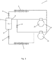
- Fig. 1 is a diagrammatic view of a vapour compression system 1 which may be used when performing a method according to an embodiment of the invention.
- the vapour compression system 1 comprises a compressor unit 2 comprising a main compressor 2a and a receiver compressor 2b, a heat rejecting heat exchanger 3, a high pressure valve 4, a receiver 5, an expansion device 6 and an evaporator 7 arranged in a refrigerant path.
- refrigerant flowing in the refrigerant path is compressed by means of the compressors 2a, 2b before being supplied to the heat rejecting heat exchanger 3.
- heat exchange takes place between the refrigerant and the ambient or a secondary fluid flow across the heat rejecting heat exchanger 3 in such a manner that heat is rejected from the refrigerant.
- the refrigerant leaving the heat rejecting heat exchanger 3 passes through the high pressure valve 4, where it undergoes expansion before entering the receiver 5.
- the refrigerant is separated into a liquid part and a gaseous part.
- the liquid part of the refrigerant leaves the receiver 5 via a liquid outlet 8, and passes through the expansion device 6, where it undergoes expansion, before being supplied to the evaporator 7.
- the refrigerant entering the evaporator 7 is thereby a mixture of liquid and gaseous refrigerant.
- the liquid part of the refrigerant is evaporated, while heat exchange takes place between the refrigerant and the ambient or a secondary fluid flow across the evaporator 7 in such a manner that heat is absorbed by the refrigerant. Finally, the refrigerant is once again supplied to the main compressor 2a.
- the gaseous part of the refrigerant in the receiver 5 may be supplied directly to the receiver compressor 2b, via a gaseous outlet 9. Thereby the gaseous part of the refrigerant does not undergo expansion in the expansion device 6, and thereby the decrease in pressure introduced in the expansion device 6 is avoided. Thereby less work is required from the compressor unit 2 in order to compress this part of the refrigerant, and therefore the energy consumption of the vapour compression system 1 can be reduced.
- the gaseous part of the refrigerant in the receiver 5 may also be supplied to the main compressor 2a, via a bypass valve 10.
- the operating setpoints could, e.g., include setpoints specifying pressure levels at various parts of the vapour compression system 1, e.g. in the receiver 5, at the outlet of the heat rejecting heat exchanger 3, at the inlet of the main compressor 2a, etc.
- the operating setpoints could include setpoints specifying temperature levels at various parts of the vapour compressions system 1, such as temperature of refrigerant leaving the heat rejecting heat exchanger 3, evaporating temperature in the evaporator 7, etc.
- the operating setpoints are configured in a manner which ensures appropriate operation of the vapour compression system 1, and in a manner which prevents conflicts between the operating setpoints.
- the operating setpoints are configured in accordance with a method according to an embodiment of the invention.
- Fig. 2 illustrates operating setpoints being provided to a setpoint manager 11 in accordance with a method according to an embodiment of the invention.
- the operating setpoints are divided into a first group of operating setpoints 12 and a second group of operating setpoints 13.
- the operating setpoints of the first group of operating setpoints 12 are generated manually by a user, via a user interface 14.
- the operating setpoints of the second group of operating setpoints 13 are generated automatically.
- the manually generated operating setpoints i.e. the operating setpoints of the first group of operating setpoints 12, as well as the automatically generated operating setpoints, i.e. the operating setpoints of the second group of operating setpoints 13, are provided to the setpoint manager 11.
- the setpoint manager 11 receives manually generated operating setpoints 12 as well as automatically generated operating setpoints 13, and these are treated on an equal footing by the setpoint manager 11.
- the setpoint manager 11 checks if the provided operating setpoints 12, 13 are in compliance with a set of rules.
- the set of rules may, e.g., specify how the operating setpoints 12, 13 must relate to each other, e.g. in terms of mutual distances between the operating setpoints 12, 13, and/or in terms of mutual order of the operating setpoints 12, 13.
- the setpoint manager 11 In the case that the setpoint manager 11 established that the provided operating setpoints 12, 13 are in compliance with the set of rules, then the provided operating setpoints 12, 13 are maintained. On the other hand, if it turns out that at least some of the provided operating setpoints 12, 13 are not in compliance with the set of rules, then the setpoint manager 11 adjusts at least some of the operating setpoints 12, 13, thereby obtaining an adjusted set of operating setpoints 12, 13, which comply with the set of rules.
- the setpoint manager 11 Based on the original or adjusted operating setpoints 12, 13, depending on whether or not the original operating setpoints 12, 13 are in compliance with the set of rules, the setpoint manager 11 applies the operating setpoints 12, 13 to control algorithms 15 and supplies the control algorithms 15 to a controller of a vapour compression system. The vapour compression system is then controlled on the basis of the control algorithms 15, and thereby in accordance with operating setpoints 12, 13.
- Fig. 3 illustrates mutual relationships among operating setpoints in accordance with a method according to an embodiment of the invention. More particularly, Fig. 3 illustrates a number of operating setpoints relating to the pressure prevailing inside a receiver of a vapour compression system, e.g. the vapour compression system illustrated in Fig. 1 . Arrow 16 represents the actual pressure in the receiver, increasing from bottom to top in the Figure.
- Pressure levels 17, 18, 19, 20, 21 and 22 each represents an operating setpoint.
- Pressure level 17 represents a receiver pumpdown limit. At receiver pressures above the receiver pumpdown limit 17, the receiver compressor(s) is/are running. However, when the pumpdown limit 17 is reached, the receiver compressor(s) is/are stopped, in order to prevent the receiver pressure 16 from decreasing further.
- Pressure level 18 represents a minimum receiver pressure, where an alarm is generated to alert the operator. Thus, it should be avoided that the pressure 16 in the receiver reaches the minimum receiver pressure 18.
- Pressure level 19 represents a proportional band (P-band) upper limit
- pressure level 20 represents a proportional band (P-band) lower limit.
- a minimum opening degree is set on the high pressure valve. If the receiver pressure 16 decreases further, the minimum opening degree is increased gradually, until the P-band lower limit 20 is reached. At this pressure level, it is no longer possible to prevent further decrease of the receiver pressure 16 by operating the high pressure valve.
- Pressure level 21 represents a hot gas dump cut-out limit
- pressure level 22 represents a hot gas dump cut-in limit.
- hot vapour from the outlet of the compressor is injected into the receiver, in an attempt to increase the receiver pressure 16, or at least prevent it from decreasing further. This is typically done by operating a solenoid valve on a hysteresis.
- the solenoid valve is opened and hot gas is injected into the receiver.
- the solenoid valve is closed, thereby stopping the injection of hot gas to the receiver.
- the P-band control as well as the hot gas dump control represent measures which can be taken in order to improve operation of the vapour compression system in the case of a low receiver pressure 16.
- the P-band control it is important that the P-band is arranged between the minimum receiver pressure 18 and the receiver pumpdown limit 17. It is also important that the P-band lower limit 20 is lower than the P-band upper limit 19. Finally, there should be minimum distances between each of the operating setpoints 17, 18, 19, 20, as indicated by double arrows, in order to ensure that the applied measure is allowed to work. Accordingly, the order of these operating setpoints, in increasing order, should be minimum receiver pressure 18, P-band lower limit 20, P-band upper limit 19, and receiver pumpdown limit 17. This may constitute a rule which the operating setpoints need to comply with. The minimum distances between the respective operating setpoints 17, 18, 19, 20 may constitute further rules.
- the hot gas dump control it is also important that the hysteresis band is arranged between the minimum receiver pressure 18 and the receiver pumpdown limit 17. Furthermore, it is important that the hot gas dump cut-in limit 22 is lower than the hot gas dump cut-out limit 21. Finally, there should be minimum distances between each of the operating setpoints 17, 18, 21, 22, as indicated by double arrows, in order to ensure that the measure is allowed to work. Accordingly, the order of these operating setpoints, in increasing order, should be minimum receiver pressure 18, hot gas dump cut-in limit 22, hot gas dump cut-out limit 21, and receiver pumpdown limit 17. This may constitute a rule which the operating setpoints need to comply with. The minimum distances between the respective operating setpoints 17, 18, 21, 22 may constitute further rules.
- the P-band control and the hot gas dump control may be applied independently of each other. Therefore, there are no rules dictating how the P-band and the hot gas dump hysteresis band should relate to each other. Thus, for instance the hot gas dump upper limit 21 may be adjusted without affecting the P-band upper limit 19 or the P-band lower limit 20.
- Fig. 4 illustrates adjustment of an operating setpoint during operation of a vapour compression system, in accordance with a method according to an embodiment of the invention. More particularly, Fig. 4 is a graph illustrating receiver pressure as a function of time.
- Line 23 represents a setpoint for the pressure in the receiver
- line 24 represents a setpoint for a pressure at the inlet of the compressor
- Line 25 represents the actual pressure in the receiver.
- the difference between the pressure 25 in the receiver and the pressure 24 at the inlet of the compressor defines a pressure difference across the expansion device.
- This pressure difference needs to be at least at a certain minimum in order to ensure a sufficient flow of liquid refrigerant into the evaporator, and thereby an appropriate operation of the vapour compression system.
- the minimum distance between the receiver pressure 25 and the pressure at the inlet of the compressor is indicated by double arrow 26. This minimum distance 26 may constitute a rule which needs to be complied with by the operating setpoints.
- the setpoint 24 for the pressure at the inlet of the compressor is temporarily lowered to a level which is at the minimum distance 26 below the receiver pressure 25. This will cause the actual pressure at the inlet of the compressor to decrease correspondingly, thereby ensuring that the minimum distance 26 is maintained.
Claims (15)
- Procédé de configuration d'une pluralité de points de réglage fonctionnels pour système de compression de vapeur (1), ce procédé comprenant les étapes suivantes :- division de la pluralité de points de réglage fonctionnels en un premier groupe (12) de points de réglage fonctionnels à générer manuellement et un second groupe (13) de points de réglage fonctionnels à générer automatiquement,- génération des points de réglage fonctionnels du premier groupe (12) manuellement et génération des points de réglage fonctionnels du second groupe (13) automatiquement,- fourniture des points de réglage fonctionnels générés manuellement (12) et des points de réglage fonctionnels générés automatiquement (13) à un gestionnaire de points de réglage (11),- le gestionnaire de points de réglage (11) vérifiant si les points de réglage fonctionnels fournis (12, 13) sont en conformité avec un ensemble de règles,- dans le cas où au moins certains des points de réglage fonctionnels fournis (12, 13) ne sont pas en conformité avec l'ensemble de règles, le gestionnaire de points de réglage (11) ajustant au moins certains des points de réglage fonctionnels fournis (12, 13) en fonction de l'ensemble de règles, en obtenant ainsi un ensemble ajusté de points de réglage fonctionnels, et- commande du système de compression de vapeur (1) en fonction de l'ensemble ajusté de points de réglage fonctionnels.
- Procédé selon la revendication 1, comprenant en outre l'étape de, dans le cas où les points de réglage fonctionnels fournis (12, 13) sont en conformité avec l'ensemble de règles, commande du système de compression de vapeur (1) en fonction des points de réglage fonctionnels fournis (12, 13).
- Procédé selon la revendication 1 ou 2, comprenant en outre les étapes suivantes :- pendant la commande du système de compression de vapeur (1), vérification si oui ou non les points de réglage fonctionnels (12, 13, 24) sont en conformité avec les conditions de fonctionnement régnantes,- dans le cas où au moins un des points de réglage fonctionnels (12, 13, 24) n'est pas en conformité avec des conditions de fonctionnement régnantes, le gestionnaire de points de réglage (11) ajustant au moins certains des points de réglage fonctionnels (12, 13, 24), en obtenant ainsi un ensemble nouvellement ajusté de points de réglage fonctionnels, et- ensuite commande du système de compression de vapeur (1) en fonction de l'ensemble nouvellement ajusté de points de réglage fonctionnels.
- Procédé selon l'une quelconque des revendications précédentes, dans lequel l'étape d'ajustement par le gestionnaire de points de réglage (11) des points de réglage fonctionnels fournis (12, 13) en fonction de l'ensemble de règles comprend le réglage de point de réglage fonctionnels du second groupe (13) avant d'ajuster les points de réglage du premier groupe (12).
- Procédé selon l'une quelconque des revendications précédentes, dans lequel l'ensemble de règles comprend des spécifications concernant les distances mutuelles entre les points de réglage fonctionnels (17, 18, 19, 20, 21, 22, 24).
- Procédé selon la revendication 5, dans lequel au moins certains des points de réglages fonctionnels fournis sont des points de réglage de pression (17, 18, 19, 20, 21, 22, 24) à appliquer pour des niveaux de pression dans diverses pièces du système de compression de vapeur (1), et l'ensemble de règles comprend des spécifications concernant des distances mutuelles (26) dans des niveaux de pression dans les diverses pièces du système de compression de vapeur (1).
- Procédé selon l'une quelconque des revendications précédentes, dans lequel l'ensemble de règles comprend des spécifications concernant l'ordre mutuel des points de réglage fonctionnels (17, 18, 19, 20, 21, 22).
- Procédé selon la revendication 7, dans lequel au moins certains des points de réglages fonctionnels fournis sont des points de réglage de pression (17, 18, 19, 20, 21, 22) à appliquer pour des niveaux de pression dans diverses pièces du système de compression de vapeur (1), et l'ensemble de règles comprend les spécifications concernant l'ordre mutuel d'au moins deux niveaux de pression dans les diverses pièces du système de compression de vapeur (1).
- Procédé selon l'une quelconque des revendications précédentes, dans lequel l'étape de division de la pluralité de points de réglage fonctionnels en un premier groupe (12) de points de réglage fonctionnels et un second groupe (13) de points de réglage fonctionnels est réalisée manuellement.
- Procédé selon l'une quelconque des revendications précédentes, le procédé étant réalisé par un système de surveillance disposé à distance par rapport au système de compression de vapeur (1).
- Procédé selon l'une quelconque des revendications précédentes, comprenant en outre l'étape de, dans le cas où au moins certains des points de réglage fonctionnels fournis (12, 13) ne sont pas en conformité avec l'ensemble de règles, génération par le gestionnaire de points de réglage (11) d'un message pour un opérateur du système de compression de vapeur (1) .
- Procédé selon la revendication 11, dans lequel le message généré par le gestionnaire de points de réglage (11) inclut des suggestions d'ajustement d'au moins certains des points de réglage fonctionnels fournis (12, 13).
- Procédé de configuration d'une pluralité de points de réglage fonctionnels pour un système de compression de vapeur (1), ce procédé comprenant les étapes suivantes :- division de la pluralité de points de réglage fonctionnels en un premier groupe (12) de points de réglage fonctionnels à générer manuellement et un second groupe (13) de points de réglage fonctionnels à générer automatiquement,- génération des points de réglage fonctionnels du premier groupe (12) manuellement, et génération des points de réglage fonctionnels du second groupe (13) automatiquement,- fourniture des points de réglage fonctionnels générés manuellement (12) et des points de réglage fonctionnels générés automatiquement (13) à un gestionnaire de points de réglage (11),- le gestionnaire de points de réglage (11) vérifiant si les points de réglage fonctionnels fournis (12, 13) sont en conformité avec un ensemble de règles, et- dans le cas où au moins certains des points de réglage fonctionnels fournis (12, 13) ne sont pas en conformité avec l'ensemble de règles, le gestionnaire de points de réglage (11) générant un message pour un opérateur du système de compression de vapeur (1).
- Procédé selon la revendication 13, dans lequel le message généré par le gestionnaire de points de réglage (11) inclut des suggestions d'ajustement d'au moins certains des points de réglage fonctionnels fournis (12, 13).
- Procédé selon la revendication 12 ou 13, dans lequel le procédé est réalisé par un système de surveillance disposé à distance par rapport au système de compression de vapeur (1).
Priority Applications (4)
| Application Number | Priority Date | Filing Date | Title |
|---|---|---|---|
| PL20215574.3T PL4016207T3 (pl) | 2020-12-18 | 2020-12-18 | Sposób konfiguracji nastaw dla układu sprężania par |
| EP20215574.3A EP4016207B1 (fr) | 2020-12-18 | 2020-12-18 | Procédé permettant de configurer des points de consigne pour un système de compression de vapeur |
| CN202111230169.2A CN114646159B (zh) | 2020-12-18 | 2021-10-21 | 用于配置蒸汽压缩系统的设定点的方法 |
| US17/514,002 US20220196305A1 (en) | 2020-12-18 | 2021-10-29 | Method for configuring setpoints for a vapour compression system |
Applications Claiming Priority (1)
| Application Number | Priority Date | Filing Date | Title |
|---|---|---|---|
| EP20215574.3A EP4016207B1 (fr) | 2020-12-18 | 2020-12-18 | Procédé permettant de configurer des points de consigne pour un système de compression de vapeur |
Publications (2)
| Publication Number | Publication Date |
|---|---|
| EP4016207A1 EP4016207A1 (fr) | 2022-06-22 |
| EP4016207B1 true EP4016207B1 (fr) | 2023-01-04 |
Family
ID=73855858
Family Applications (1)
| Application Number | Title | Priority Date | Filing Date |
|---|---|---|---|
| EP20215574.3A Active EP4016207B1 (fr) | 2020-12-18 | 2020-12-18 | Procédé permettant de configurer des points de consigne pour un système de compression de vapeur |
Country Status (4)
| Country | Link |
|---|---|
| US (1) | US20220196305A1 (fr) |
| EP (1) | EP4016207B1 (fr) |
| CN (1) | CN114646159B (fr) |
| PL (1) | PL4016207T3 (fr) |
Family Cites Families (15)
| Publication number | Priority date | Publication date | Assignee | Title |
|---|---|---|---|---|
| US6250382B1 (en) * | 1999-05-04 | 2001-06-26 | York International Corporation | Method and system for controlling a heating, ventilating, and air conditioning unit |
| US8596550B2 (en) * | 2009-05-12 | 2013-12-03 | Ecofactor, Inc. | System, method and apparatus for identifying manual inputs to and adaptive programming of a thermostat |
| US9182154B2 (en) * | 2012-01-20 | 2015-11-10 | Mitsubishi Electric Research Laboratories, Inc. | Adaptive control of vapor compression system |
| US9879892B2 (en) | 2012-02-21 | 2018-01-30 | Danfoss A/S | Method for configuring a refrigeration system |
| US9658609B2 (en) * | 2014-05-06 | 2017-05-23 | Lennox Industries Inc. | Device assisted settings adjustment for HVAC controllers |
| CN108603709B (zh) * | 2016-02-03 | 2020-07-07 | 丹佛斯有限公司 | 一种用于根据可变温度设定点来控制蒸汽压缩系统的风扇的方法 |
| US10094598B2 (en) * | 2016-06-06 | 2018-10-09 | Mitsubishi Electric Research Laboratories, Inc. | System and method for controlling multi-zone vapor compression system |
| JP7017096B2 (ja) * | 2018-02-28 | 2022-02-08 | 株式会社富士通ゼネラル | 空気調和機 |
| US11353246B2 (en) * | 2018-06-11 | 2022-06-07 | Hill Phoenix, Inc. | CO2 refrigeration system with automated control optimization |
| PL3628942T3 (pl) * | 2018-09-25 | 2021-10-04 | Danfoss A/S | Sposób sterowania układem sprężania pary przy zmniejszonym ciśnieniu ssania |
| JP6885497B2 (ja) * | 2019-06-21 | 2021-06-16 | ダイキン工業株式会社 | 情報処理方法、情報処理装置、及びプログラム |
| CN114730163A (zh) * | 2019-09-18 | 2022-07-08 | 江森自控泰科知识产权控股有限责任合伙公司 | 用于改进温度、压力和湿度的合规性的建筑系统 |
| US11782397B2 (en) * | 2019-11-27 | 2023-10-10 | Johnson Controls Tyco IP Holdings LLP | Operator automation system |
| US11703238B2 (en) * | 2020-03-12 | 2023-07-18 | Johnson Controls Tyco IP Holdings LLP | Remote access control of HVAC system |
| US20220082286A1 (en) * | 2020-09-11 | 2022-03-17 | Johnson Controls Tyco IP Holdings LLP | Control system for an hvac system |
-
2020
- 2020-12-18 EP EP20215574.3A patent/EP4016207B1/fr active Active
- 2020-12-18 PL PL20215574.3T patent/PL4016207T3/pl unknown
-
2021
- 2021-10-21 CN CN202111230169.2A patent/CN114646159B/zh active Active
- 2021-10-29 US US17/514,002 patent/US20220196305A1/en active Pending
Also Published As
| Publication number | Publication date |
|---|---|
| PL4016207T3 (pl) | 2023-05-08 |
| CN114646159B (zh) | 2023-11-28 |
| US20220196305A1 (en) | 2022-06-23 |
| EP4016207A1 (fr) | 2022-06-22 |
| CN114646159A (zh) | 2022-06-21 |
Similar Documents
| Publication | Publication Date | Title |
|---|---|---|
| US10612794B2 (en) | Controlled hydronic distribution system | |
| TWI557384B (zh) | 控制系統 | |
| AU2014209299B2 (en) | System and method for control of a transcritical refrigeration system | |
| US7743617B2 (en) | Chiller sound reduction control system and method | |
| CN110332664A (zh) | 一种空调器控制方法和空调器 | |
| EP1725816B1 (fr) | Commande multi-variables pour systèmes de réfrigérant | |
| EP3545243B1 (fr) | Procédé de commande d'un système de compression de vapeur pendant un dysfonctionnement de soupape de dérivation de gaz | |
| KR102122592B1 (ko) | 공기조화시스템의 제어방법 | |
| CN107036245B (zh) | 多联机系统及其室外压缩机的控制装置和方法 | |
| JP2007100699A (ja) | 空調装置用可変容量圧縮機の制御方法 | |
| CN109764491A (zh) | 一种数据中心空调控制系统、控制方法及存储介质 | |
| CN102466303A (zh) | 控制装置以及控制方法 | |
| EP3273187A2 (fr) | Diagnostics de compresseur pour un système de réfrigération extérieur modulaire | |
| EP3236180A1 (fr) | Optimisation de la température et de la pression de liquide dans un système de réfrigération extérieur modulaire | |
| EP4016207B1 (fr) | Procédé permettant de configurer des points de consigne pour un système de compression de vapeur | |
| EP1730455B1 (fr) | Algorithme de commande non lineaire utilise dans des systemes de compression de vapeur | |
| CN110131860B (zh) | 用于控制空调器的运行的控制方法和空调器 | |
| EP3222943A1 (fr) | Système et procédé de maintien de la surchauffe d'évaporateur pendant l'opération de pompage de l'économiseur de frigorigène | |
| CN115930495A (zh) | 制冷设施的调节方法和调节装置及相应制冷设施 | |
| JP2020143853A (ja) | 空調システム及びその制御方法 | |
| GB2521469B (en) | Evaporator Control | |
| CN111121153B (zh) | 一种多联内机与新风机混接系统及其控制方法 | |
| CN110168453B (zh) | 用于冷水crac单元自适应pid控制 | |
| CN107869865B (zh) | 在泵运行模式期间对过热水平进行控制的方法及制冷系统 | |
| CN117606173A (zh) | 膨胀阀控制方法及热泵装置 |
Legal Events
| Date | Code | Title | Description |
|---|---|---|---|
| PUAI | Public reference made under article 153(3) epc to a published international application that has entered the european phase |
Free format text: ORIGINAL CODE: 0009012 |
|
| STAA | Information on the status of an ep patent application or granted ep patent |
Free format text: STATUS: REQUEST FOR EXAMINATION WAS MADE |
|
| 17P | Request for examination filed |
Effective date: 20211122 |
|
| AK | Designated contracting states |
Kind code of ref document: A1 Designated state(s): AL AT BE BG CH CY CZ DE DK EE ES FI FR GB GR HR HU IE IS IT LI LT LU LV MC MK MT NL NO PL PT RO RS SE SI SK SM TR |
|
| INTG | Intention to grant announced |
Effective date: 20221026 |
|
| STAA | Information on the status of an ep patent application or granted ep patent |
Free format text: STATUS: GRANT OF PATENT IS INTENDED |
|
| GRAS | Grant fee paid |
Free format text: ORIGINAL CODE: EPIDOSNIGR3 |
|
| GRAA | (expected) grant |
Free format text: ORIGINAL CODE: 0009210 |
|
| STAA | Information on the status of an ep patent application or granted ep patent |
Free format text: STATUS: THE PATENT HAS BEEN GRANTED |
|
| AK | Designated contracting states |
Kind code of ref document: B1 Designated state(s): AL AT BE BG CH CY CZ DE DK EE ES FI FR GB GR HR HU IE IS IT LI LT LU LV MC MK MT NL NO PL PT RO RS SE SI SK SM TR |
|
| REG | Reference to a national code |
Ref country code: GB Ref legal event code: FG4D |
|
| REG | Reference to a national code |
Ref country code: DE Ref legal event code: R096 Ref document number: 602020007359 Country of ref document: DE |
|
| REG | Reference to a national code |
Ref country code: CH Ref legal event code: EP |
|
| REG | Reference to a national code |
Ref country code: AT Ref legal event code: REF Ref document number: 1542404 Country of ref document: AT Kind code of ref document: T Effective date: 20230115 |
|
| REG | Reference to a national code |
Ref country code: IE Ref legal event code: FG4D |
|
| REG | Reference to a national code |
Ref country code: LT Ref legal event code: MG9D |
|
| REG | Reference to a national code |
Ref country code: NL Ref legal event code: MP Effective date: 20230104 |
|
| REG | Reference to a national code |
Ref country code: AT Ref legal event code: MK05 Ref document number: 1542404 Country of ref document: AT Kind code of ref document: T Effective date: 20230104 |
|
| PG25 | Lapsed in a contracting state [announced via postgrant information from national office to epo] |
Ref country code: NL Free format text: LAPSE BECAUSE OF FAILURE TO SUBMIT A TRANSLATION OF THE DESCRIPTION OR TO PAY THE FEE WITHIN THE PRESCRIBED TIME-LIMIT Effective date: 20230104 |
|
| P01 | Opt-out of the competence of the unified patent court (upc) registered |
Effective date: 20230617 |
|
| PG25 | Lapsed in a contracting state [announced via postgrant information from national office to epo] |
Ref country code: RS Free format text: LAPSE BECAUSE OF FAILURE TO SUBMIT A TRANSLATION OF THE DESCRIPTION OR TO PAY THE FEE WITHIN THE PRESCRIBED TIME-LIMIT Effective date: 20230104 Ref country code: PT Free format text: LAPSE BECAUSE OF FAILURE TO SUBMIT A TRANSLATION OF THE DESCRIPTION OR TO PAY THE FEE WITHIN THE PRESCRIBED TIME-LIMIT Effective date: 20230504 Ref country code: NO Free format text: LAPSE BECAUSE OF FAILURE TO SUBMIT A TRANSLATION OF THE DESCRIPTION OR TO PAY THE FEE WITHIN THE PRESCRIBED TIME-LIMIT Effective date: 20230404 Ref country code: LV Free format text: LAPSE BECAUSE OF FAILURE TO SUBMIT A TRANSLATION OF THE DESCRIPTION OR TO PAY THE FEE WITHIN THE PRESCRIBED TIME-LIMIT Effective date: 20230104 Ref country code: LT Free format text: LAPSE BECAUSE OF FAILURE TO SUBMIT A TRANSLATION OF THE DESCRIPTION OR TO PAY THE FEE WITHIN THE PRESCRIBED TIME-LIMIT Effective date: 20230104 Ref country code: HR Free format text: LAPSE BECAUSE OF FAILURE TO SUBMIT A TRANSLATION OF THE DESCRIPTION OR TO PAY THE FEE WITHIN THE PRESCRIBED TIME-LIMIT Effective date: 20230104 Ref country code: ES Free format text: LAPSE BECAUSE OF FAILURE TO SUBMIT A TRANSLATION OF THE DESCRIPTION OR TO PAY THE FEE WITHIN THE PRESCRIBED TIME-LIMIT Effective date: 20230104 Ref country code: AT Free format text: LAPSE BECAUSE OF FAILURE TO SUBMIT A TRANSLATION OF THE DESCRIPTION OR TO PAY THE FEE WITHIN THE PRESCRIBED TIME-LIMIT Effective date: 20230104 |
|
| PG25 | Lapsed in a contracting state [announced via postgrant information from national office to epo] |
Ref country code: SE Free format text: LAPSE BECAUSE OF FAILURE TO SUBMIT A TRANSLATION OF THE DESCRIPTION OR TO PAY THE FEE WITHIN THE PRESCRIBED TIME-LIMIT Effective date: 20230104 Ref country code: IS Free format text: LAPSE BECAUSE OF FAILURE TO SUBMIT A TRANSLATION OF THE DESCRIPTION OR TO PAY THE FEE WITHIN THE PRESCRIBED TIME-LIMIT Effective date: 20230504 Ref country code: GR Free format text: LAPSE BECAUSE OF FAILURE TO SUBMIT A TRANSLATION OF THE DESCRIPTION OR TO PAY THE FEE WITHIN THE PRESCRIBED TIME-LIMIT Effective date: 20230405 Ref country code: FI Free format text: LAPSE BECAUSE OF FAILURE TO SUBMIT A TRANSLATION OF THE DESCRIPTION OR TO PAY THE FEE WITHIN THE PRESCRIBED TIME-LIMIT Effective date: 20230104 |
|
| REG | Reference to a national code |
Ref country code: DE Ref legal event code: R097 Ref document number: 602020007359 Country of ref document: DE |
|
| PG25 | Lapsed in a contracting state [announced via postgrant information from national office to epo] |
Ref country code: SM Free format text: LAPSE BECAUSE OF FAILURE TO SUBMIT A TRANSLATION OF THE DESCRIPTION OR TO PAY THE FEE WITHIN THE PRESCRIBED TIME-LIMIT Effective date: 20230104 Ref country code: RO Free format text: LAPSE BECAUSE OF FAILURE TO SUBMIT A TRANSLATION OF THE DESCRIPTION OR TO PAY THE FEE WITHIN THE PRESCRIBED TIME-LIMIT Effective date: 20230104 Ref country code: EE Free format text: LAPSE BECAUSE OF FAILURE TO SUBMIT A TRANSLATION OF THE DESCRIPTION OR TO PAY THE FEE WITHIN THE PRESCRIBED TIME-LIMIT Effective date: 20230104 Ref country code: DK Free format text: LAPSE BECAUSE OF FAILURE TO SUBMIT A TRANSLATION OF THE DESCRIPTION OR TO PAY THE FEE WITHIN THE PRESCRIBED TIME-LIMIT Effective date: 20230104 Ref country code: CZ Free format text: LAPSE BECAUSE OF FAILURE TO SUBMIT A TRANSLATION OF THE DESCRIPTION OR TO PAY THE FEE WITHIN THE PRESCRIBED TIME-LIMIT Effective date: 20230104 |
|
| PLBE | No opposition filed within time limit |
Free format text: ORIGINAL CODE: 0009261 |
|
| STAA | Information on the status of an ep patent application or granted ep patent |
Free format text: STATUS: NO OPPOSITION FILED WITHIN TIME LIMIT |
|
| PG25 | Lapsed in a contracting state [announced via postgrant information from national office to epo] |
Ref country code: SK Free format text: LAPSE BECAUSE OF FAILURE TO SUBMIT A TRANSLATION OF THE DESCRIPTION OR TO PAY THE FEE WITHIN THE PRESCRIBED TIME-LIMIT Effective date: 20230104 |
|
| 26N | No opposition filed |
Effective date: 20231005 |
|
| PG25 | Lapsed in a contracting state [announced via postgrant information from national office to epo] |
Ref country code: SI Free format text: LAPSE BECAUSE OF FAILURE TO SUBMIT A TRANSLATION OF THE DESCRIPTION OR TO PAY THE FEE WITHIN THE PRESCRIBED TIME-LIMIT Effective date: 20230104 |
|
| PGFP | Annual fee paid to national office [announced via postgrant information from national office to epo] |
Ref country code: FR Payment date: 20231108 Year of fee payment: 4 Ref country code: DE Payment date: 20231031 Year of fee payment: 4 |
|
| PGFP | Annual fee paid to national office [announced via postgrant information from national office to epo] |
Ref country code: PL Payment date: 20231116 Year of fee payment: 4 |