EP4016192B1 - Mecanisme de transmission pour mouvement horloger - Google Patents
Mecanisme de transmission pour mouvement horloger Download PDFInfo
- Publication number
- EP4016192B1 EP4016192B1 EP21212068.7A EP21212068A EP4016192B1 EP 4016192 B1 EP4016192 B1 EP 4016192B1 EP 21212068 A EP21212068 A EP 21212068A EP 4016192 B1 EP4016192 B1 EP 4016192B1
- Authority
- EP
- European Patent Office
- Prior art keywords
- mobile
- rotation
- arm
- drive
- connecting member
- Prior art date
- Legal status (The legal status is an assumption and is not a legal conclusion. Google has not performed a legal analysis and makes no representation as to the accuracy of the status listed.)
- Active
Links
Images
Classifications
-
- G—PHYSICS
- G04—HOROLOGY
- G04B—MECHANICALLY-DRIVEN CLOCKS OR WATCHES; MECHANICAL PARTS OF CLOCKS OR WATCHES IN GENERAL; TIME PIECES USING THE POSITION OF THE SUN, MOON OR STARS
- G04B11/00—Click devices; Stop clicks; Clutches
- G04B11/02—Devices allowing the motion of a rotatable part in only one direction
- G04B11/022—Devices allowing the motion of a rotatable part in only one direction with a ratchet which makes contact with the rotating member by means of teeth
- G04B11/024—Devices allowing the motion of a rotatable part in only one direction with a ratchet which makes contact with the rotating member by means of teeth rotatable about a fixed axis by means of spring action
-
- G—PHYSICS
- G04—HOROLOGY
- G04B—MECHANICALLY-DRIVEN CLOCKS OR WATCHES; MECHANICAL PARTS OF CLOCKS OR WATCHES IN GENERAL; TIME PIECES USING THE POSITION OF THE SUN, MOON OR STARS
- G04B11/00—Click devices; Stop clicks; Clutches
- G04B11/006—Clutch mechanism between two rotating members with transfer of movement in only one direction (free running devices)
-
- G—PHYSICS
- G04—HOROLOGY
- G04B—MECHANICALLY-DRIVEN CLOCKS OR WATCHES; MECHANICAL PARTS OF CLOCKS OR WATCHES IN GENERAL; TIME PIECES USING THE POSITION OF THE SUN, MOON OR STARS
- G04B5/00—Automatic winding up
- G04B5/02—Automatic winding up by self-winding caused by the movement of the watch
- G04B5/04—Automatic winding up by self-winding caused by the movement of the watch by oscillating weights the movement of which is limited
- G04B5/06—Automatic winding up by self-winding caused by the movement of the watch by oscillating weights the movement of which is limited acting in one direction only
-
- G—PHYSICS
- G04—HOROLOGY
- G04B—MECHANICALLY-DRIVEN CLOCKS OR WATCHES; MECHANICAL PARTS OF CLOCKS OR WATCHES IN GENERAL; TIME PIECES USING THE POSITION OF THE SUN, MOON OR STARS
- G04B13/00—Gearwork
- G04B13/02—Wheels; Pinions; Spindles; Pivots
-
- G—PHYSICS
- G04—HOROLOGY
- G04B—MECHANICALLY-DRIVEN CLOCKS OR WATCHES; MECHANICAL PARTS OF CLOCKS OR WATCHES IN GENERAL; TIME PIECES USING THE POSITION OF THE SUN, MOON OR STARS
- G04B11/00—Click devices; Stop clicks; Clutches
- G04B11/006—Clutch mechanism between two rotating members with transfer of movement in only one direction (free running devices)
- G04B11/008—Clutch mechanism between two rotating members with transfer of movement in only one direction (free running devices) with friction members, e.g. click springs or jumper
-
- G—PHYSICS
- G04—HOROLOGY
- G04B—MECHANICALLY-DRIVEN CLOCKS OR WATCHES; MECHANICAL PARTS OF CLOCKS OR WATCHES IN GENERAL; TIME PIECES USING THE POSITION OF THE SUN, MOON OR STARS
- G04B11/00—Click devices; Stop clicks; Clutches
- G04B11/02—Devices allowing the motion of a rotatable part in only one direction
-
- G—PHYSICS
- G04—HOROLOGY
- G04B—MECHANICALLY-DRIVEN CLOCKS OR WATCHES; MECHANICAL PARTS OF CLOCKS OR WATCHES IN GENERAL; TIME PIECES USING THE POSITION OF THE SUN, MOON OR STARS
- G04B5/00—Automatic winding up
- G04B5/02—Automatic winding up by self-winding caused by the movement of the watch
- G04B5/04—Automatic winding up by self-winding caused by the movement of the watch by oscillating weights the movement of which is limited
- G04B5/08—Automatic winding up by self-winding caused by the movement of the watch by oscillating weights the movement of which is limited acting in both directions
-
- G—PHYSICS
- G04—HOROLOGY
- G04B—MECHANICALLY-DRIVEN CLOCKS OR WATCHES; MECHANICAL PARTS OF CLOCKS OR WATCHES IN GENERAL; TIME PIECES USING THE POSITION OF THE SUN, MOON OR STARS
- G04B5/00—Automatic winding up
- G04B5/02—Automatic winding up by self-winding caused by the movement of the watch
- G04B5/18—Supports, suspensions or guide arrangements, for oscillating weights
Definitions
- the present invention relates to a transmission mechanism, for a watch movement, intended to transmit the movements of a driving mobile to a driven mobile of the watch movement, the mechanism comprising a transmission mobile comprising a drive board, intended to be kinematically connected to the driving mobile and to pivot along a first fixed axis of rotation in response to the movements of the driving mobile, as well as a connecting member having a flexible portion and carrying a unidirectional transmission member arranged to cooperate with a drive surface of an output mobile intended to be connected to the driven mobile, and to drive it when the driving mobile moves in a first direction of movement.
- the invention relates to an automatic winding mechanism comprising a transmission mechanism of this type for connecting a winding mass and a mechanical energy storage device.
- the present invention also relates to a watch movement provided with such a transmission mechanism as well as a timepiece comprising such a watch movement.
- the patent EP 3203326 B1 illustrates and describes a transmission mechanism meeting the above characteristics. More specifically, this transmission mechanism is intended to convert the bidirectional rotational movement of a winding mass into a unidirectional movement for ensuring the winding of a barrel spring.
- the mechanism comprises a first rotary mobile intended to be driven by the movements of the winding mass, in one direction or the other.
- This first mobile carries a disc of transmission eccentric relative to the axis of rotation of the first mobile and arranged to drive a transmission member in a circular translational movement.
- the transmission member in turn cooperates with a clutch member arranged to allow unidirectional rotational drive of an output mobile intended to be connected to one end of a barrel spring, to ensure the loading of the latter.
- the transmission member carries two drive surfaces capable of having a connection by bracing with the clutch member, each of which is associated with a given direction of rotation.
- the drive surfaces are alternately brought closer to and moved away from the clutch member, in a back-and-forth movement, due to the circular translational movement of the transmission member.
- the drive surfaces cooperate alternately with the clutch member to drive it in rotation in a single direction of rotation.
- the patent FR 1022726 concerns another automatic winding mechanism.
- a main object of the present invention is to provide a clock transmission mechanism having a more compact and substantially simplified alternative construction with reference to the conversion mechanism described in the patent EP 3203326 B1 .
- the present invention relates more particularly to a transmission mechanism of the type indicated above, in which the connecting member comprises a base secured to the drive board and arranged to present a rotational movement along the first fixed axis of rotation, in response to the movements of the driving mobile, and wherein the connecting member comprises a first arm extending from the base and carrying the one-way transmission member at its distal end, the flexible portion being arranged on the arm so as to allow deformation of the latter when the connecting member is rotated.
- the arm of the connecting member can be shaped and sized, including for its flexible portion, so as to ensure the proper implementation of the unidirectional drive of the output mobile by the unidirectional transmission member, while driving the connecting member following a simple rotational movement.
- the arm carries at least one additional flexible portion.
- This feature provides more flexibility to the mechanism manufacturer in choosing the shape of the arm.
- the output mobile when the output mobile is intended to be pivoted along a second fixed axis of rotation, it may further be provided that the distal end of the arm is secured to a radial guide arm arranged to pivot along the second fixed axis of rotation while being free to rotate with reference to the output mobile.
- the arm of the connecting member or the radial guide arm carries an elastic return member arranged to act on the unidirectional transmission member and tend to position it in a predefined rest position.
- the connecting member carries a second arm, having structural characteristics similar to those of the first arm and carrying an additional unidirectional transmission member, arranged to drive the drive surface of the output mobile when the driving mobile moves in a second direction of movement, opposite to the first direction of movement.
- first and second arms extend in respective general directions inclined relative to each other at an angle of between 70 and 110 degrees.
- the present invention relates to an automatic winding mechanism comprising a transmission mechanism meeting in whole or in part the characteristics which have just been set out, and comprising a winding mass intended to be mounted on a frame element of the watch movement so as to be able to pivot with reference to the latter and having a kinematic connection with the drive board.
- the winding mass is arranged to exhibit oscillating movements of low amplitude, preferably less than 20 degrees, more preferably less than 10 degrees.
- the present invention generally relates to a watch movement comprising a transmission mechanism meeting the characteristics set out above, whether or not it is integrated into an automatic winding mechanism, as well as a timepiece comprising such a watch movement.
- the detailed description which follows seeks to describe a transmission clockwork mechanism according to a preferred embodiment of the present invention as a non-limiting illustrative example. More precisely, according to the illustrated and described embodiment, the transmission mechanism is intended to be integrated into an automatic winding mechanism of a timepiece but, of course, the person skilled in the art will be able to implement the transmission mechanism according to the invention in relation to other types of clockwork mechanisms without departing from the scope of the present invention as defined in the set of claims.
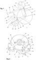
- FIG. 1 represents a schematic diagram of part of a transmission mechanism 1 according to the invention allowing the general operating principle to be explained.
- the transmission mechanism 1 is intended to convert bidirectional rotation movements of a driving mobile (not shown) into unidirectional rotation movements of a driven mobile.
- the transmission mechanism 1 comprises in particular a connecting member 2 intended to be driven in bidirectional rotation from the movements of the mobile driving and in turn driving an output mobile 4 following a unidirectional rotational movement.
- the transmission mechanism 1 When the transmission mechanism 1 according to the invention is integrated into an automatic winding mechanism, it can advantageously be arranged to convert the bidirectional rotational movements of a winding mass (not shown) into unidirectional rotational movements, before the latter are transmitted to a mechanical energy storage member to charge it with mechanical energy, typically a barrel spring (not shown).
- the connecting member 2 comprises a base 6 intended to be rotatably mounted on a frame element of a watch movement.
- the base 6 carries two arms 8, 10 extending in general directions inclined relative to each other, towards a region close to the periphery of the output wheel set 4, intended to be kinematically connected to the mechanical energy storage member in the case of an automatic winding mechanism.
- Each of the arms 8, 10 comprises, at its distal end, a support 14, 16 on which a unidirectional transmission member 18, 20, having the general shape of a circular wheel, is rotatably mounted, along an axis of rotation 22, 24.
- a radial guide arm 26, 28 is provided to connect each support 14, 16 to the axis of rotation 30 of the output mobile 4 and thus maintain the corresponding axis of rotation 22, 24 at a constant distance from the axis of rotation 30.
- each of the rotation axes 22, 24 is slightly offset relative to a radius passing through the rotation axis 30 of the output wheel set 4 and the point of contact of the latter with the corresponding unidirectional transmission member.
- each rotation axis 22, 24 is preferably slightly eccentric relative to the circular periphery of the corresponding unidirectional transmission member, the latter defining a contact surface with the output wheel set 4.
- the one-way transmission member 18 when the connecting member 2 rotates counterclockwise on the view of the figure 1 , the one-way transmission member 18 also rotates in the counterclockwise direction. By following such a movement, its radius located between its axis of rotation 22 and its point of contact with the periphery of the output mobile 4 tends to decrease. The one-way transmission member 18 can therefore rotate freely (again, if it was in a bracing situation) relative to the output mobile 4. Thus, when the connecting member 2 pivots in the counterclockwise direction of rotation, the one-way transmission member 18 does not drive the output mobile 4 in rotation.
- the other one-way transmission member 20 is mounted on its support 16 in a manner similar to that of the one-way transmission member 18.
- the arms 8 and 10 extend on either side of the straight line passing through the centers of the connecting member 2 and the output mobile 4.
- the two one-way transmission members 18 and 20 cooperate with the periphery of the output mobile 4 in such a way that they pivot in respective opposite directions of rotation. Consequently, each of the one-way transmission members 18, 20 is associated with a given direction of rotation of the connecting member 2, in which it has a bracing connection with the output mobile 4 to drive the latter in rotation.
- a rotation of the connecting member 2 in the clockwise rotation direction therefore causes a rotation of the unidirectional transmission member 18 in the same direction, which tends to place it in a situation of buttressing with the output mobile 4 to drive the latter in the clockwise rotation direction.
- the unidirectional transmission member 20 rotates freely in the counterclockwise direction without exerting any particular action on the periphery of the output mobile 4.
- a rotation of the connecting member 2 in the counterclockwise direction of rotation causes a free rotation in the same direction of the unidirectional transmission member 18, with reference to the output mobile 4.
- the unidirectional transmission member 20 rotates clockwise, which tends to place it in a situation of buttressing with the output mobile 4 to drive the latter in the clockwise direction of rotation.
- the unidirectional transmission members 18, 20 alternately ensure the driving of the output mobile 4 in one and the same direction.
- a return spring 32 is preferably associated with each unidirectional transmission member 18, 20, cooperating with a pin 34 integral with the latter, to prevent its orientation from straying too far from the orientation in which the interaction by bracing with the output mobile 4 occurs, and thus ensure greater responsiveness to the transmission mechanism according to the invention, in particular during changes in the direction of drive of the connecting member 2.
- the operating principle just described can be implemented with a single arm carrying a single unidirectional transmission member.
- the transmission mechanism is integrated into an automatic winding mechanism for example, only one direction of rotation of the winding mass will contribute to the load of the mechanical energy storage member.
- each of the arms 8, 10 has, between its proximal end secured to the base 6 of the connecting member 2 and its distal end comprising the corresponding support 14, 16, two flexible portions 36 intended to allow the arm 8, 10 to deform when the connecting member 2 is driven in rotation, while ensuring adequate guidance of the corresponding unidirectional transmission member 18, 20.
- the transmission mechanism comprises two arms 8, 10
- the latter may advantageously have an angle of the order of 70 to 110 degrees between them but, of course, the person skilled in the art will also be able to adapt this indicative value according to the shape finally chosen to produce the arms and according to the number of flexible portions that they will comprise.
- the two arms do not necessarily comprise the same number of flexible portions.
- FIG 2 represents a simplified perspective view of a part of a transmission mechanism 1 according to a preferred embodiment of the present invention, seen from a first face, allowing certain construction details to be better appreciated.
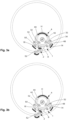
- Figures 3a and 3b represent the same front view of the transmission mechanism 1 of the figure 2 , seen from its second side and in two different respective operating phases.
- the connecting member 2 is associated with a toothed drive board 40, integral in rotation of the base 6, to define a transmission mobile.
- the drive board 40 is intended to have, via its teeth, a kinematic connection with the driving mobile, for example a winding mass, to ensure the driving of the base 6 and therefore of the arms 8, 10.
- the drive board 40 may of course be made in one piece with the base 6 without departing from the scope of the invention and/or may include other means of connection with the driving mobile. Indeed, other modes of connection between the connecting member 2 and the driving mobile may be implemented without departing from the scope of the invention.
- each of these organs has the shape of a skate with a slight asymmetry in reference to its median plane. It appears from a careful examination of the Figures 3a and 3b that each skate has a slightly larger radius to the left of its median plane than to the right.
- the drive board 40 is arranged in engagement with an intermediate connecting mobile 52 intended to be driven in rotation by the driving mobile.
- the driving mobile performs small oscillations around an equilibrium position, such that the mobile intermediate connecting member 52 is driven to exhibit back and forth movements, as is the connecting member 2.
- the member 50 enters into a bracing-type relationship with the first driven wheel 42, while the member 48 is free to rotate without acting on this same wheel 42.
- FIG. 3b illustrates the operation of the transmission mechanism 1 when the intermediate connecting wheel 52 is rotated in the counterclockwise direction.
- the connecting member 2 is then rotated in the clockwise direction and the distal ends of the arms 8, 10 approach the base 6 of the connecting member 2.
- the unidirectional transmission member 50 cooperates with the first driven wheel 42 so as to pivot in the counterclockwise direction of rotation, while the member 48 pivots in the clockwise direction of rotation, in the view of the figure 3b .
- the member 48 has an increasing radius with respect to the first driven wheel 42, while the member 50 has a decreasing radius with respect to this same wheel 42.
- the unidirectional transmission member 48, 50 which is in an arching relationship with the first driven wheel 42 leaves this state by rapidly presenting a decreasing radius allowing it to pivot without interacting with the first driven wheel 42. Conversely, the other unidirectional transmission member rapidly presents an increasing radius to the first driven wheel 42 and enters into an arching type relationship with it.
- a clockwork mechanism for transmitting a rotational movement between a driving mobile and a driven mobile, with unidirectional conversion, having a construction and a method of assembly that are at once simple, precise and reliable.
- this mechanism operates with less friction than the previous solution described above and thus offers excellent efficiency.
- the implementation of the present invention is not limited to the exact geometry of the various components of the mechanism as illustrated and described. Indeed, the person skilled in the art will not encounter any particular difficulty in adapting the present teaching to the implementation of a transmission mechanism meeting the characteristics of the present invention, by implementing a number of arms of the connecting member adapted to his own needs, as well as the number and location of their flexible portions, or even the shape of the unidirectional transmission members or their method of implantation in the transmission mechanism.
- such a transmission mechanism is perfectly suited to integration into an automatic winding mechanism for transmitting the bidirectional movements of a winding mass to a mechanical energy storage member, but it may be implemented in relation to any other type of suitable watch system without departing from the scope of the invention as defined by the attached set of claims.
- the winding mass may advantageously be arranged to exhibit oscillating movements of low amplitude, preferably less than 20 degrees, more preferably less than 10 degrees, to promote the construction of a compact automatic winding mechanism.
Landscapes
- Physics & Mathematics (AREA)
- General Physics & Mathematics (AREA)
- Transmission Devices (AREA)
- Gears, Cams (AREA)
Description
- La présente invention concerne un mécanisme de transmission, pour mouvement horloger, destiné à transmettre les mouvements d'un mobile entrainant à un mobile entraîné du mouvement horloger, le mécanisme comportant un mobile de transmission comprenant une planche d'entrainement, destinée à être reliée cinématiquement au mobile entrainant et à pivoter suivant un premier axe de rotation fixe en réponse aux mouvements du mobile entraînant, ainsi qu'un organe de liaison présentant une portion flexible et portant un organe de transmission unidirectionnelle agencé pour coopérer avec une surface d'entrainement d'un mobile de sortie destiné à être relié au mobile entraîné, et pour l'entrainer lorsque le mobile entrainant se déplace dans un premier sens de déplacement.
- Selon un mode de réalisation préféré, l'invention concerne un mécanisme de remontage automatique comportant un mécanisme de transmission de ce type pour faire le lien entre une masse de remontage et un dispositif de stockage d'énergie mécanique.
- La présente invention concerne également un mouvement horloger muni d'un tel mécanisme de transmission ainsi qu'une pièce d'horlogerie comprenant un tel mouvement horloger.
- Des mécanismes horlogers de ce type sont déjà connus dans l'art antérieur, en particulier en relation avec des mécanismes de remontage automatique.
- Ainsi, par exemple, le brevet
EP 3203326 B1 illustre et décrit un mécanisme de transmission répondant aux caractéristiques ci-dessus. Plus précisément, ce mécanisme de transmission est destiné à convertir le mouvement de rotation bidirectionnel d'une masse de remontage en un mouvement unidirectionnel permettant d'assurer le remontage d'un ressort de barillet. A cet effet, le mécanisme comporte un premier mobile rotatif destiné à être entraîné par les mouvements de la masse de remontage, dans un sens ou dans l'autre. Ce premier mobile porte un disque de transmission excentré par rapport à l'axe de rotation du premier mobile et agencé pour entraîner un organe de transmission suivant un mouvement de translation circulaire. L'organe de transmission coopère à son tour avec un organe d'embrayage agencé pour permettre un entrainement en rotation unidirectionnel d'un mobile de sortie destiné à être relié à une extrémité d'un ressort de barillet, pour assurer la charge de ce dernier. A cet effet, l'organe de transmission porte deux surfaces d'entrainement susceptibles de présenter une liaison par arc-boutement avec l'organe d'embrayage, dont chacune est associée à un sens de rotation donné. Pour chaque sens de rotation de la masse de remontage, les surfaces d'entrainement sont alternativement rapprochées et éloignées de l'organe d'embrayage, dans un mouvement de va-et-vient, du fait du mouvement de translation circulaire de l'organe de transmission. Ainsi, les surfaces d'entrainement coopèrent en alternance avec l'organe d'embrayage pour l'entrainer en rotation dans un seul et même sens de rotation. - Une telle construction nécessite une grande précision dans la réalisation et dans le positionnement des différents composants impliqués, pour assurer que la trajectoire des surfaces d'entrainement permette d'obtenir effectivement la liaison par arc-boutement visée avec l'organe d'embrayage.
- Le brevet
FR 1022726 - Un but principal de la présente invention est de proposer un mécanisme de transmission horloger présentant une construction alternative plus compacte et sensiblement simplifiée en référence au mécanisme de conversion décrit dans le brevet
EP 3203326 B1 . - A cet effet, la présente invention concerne plus particulièrement un mécanisme de transmission du type indiqué plus haut, dans lequel l'organe de liaison comporte une base solidaire de la planche d'entrainement et agencée pour présenter un mouvement de rotation suivant le premier axe de rotation fixe, en réponse aux mouvements du mobile entraînant, et
dans lequel l'organe de liaison comprend un premier bras s'étendant depuis la base et portant l'organe de transmission unidirectionnelle à son extrémité distale, la portion flexible étant agencée sur le bras de manière à permettre une déformation de ce dernier lorsque l'organe de liaison est entraîné en rotation. - Grâce à ces caractéristiques, le bras de l'organe de liaison peut être conformé et dimensionné, y compris pour sa portion flexible, de manière à assurer la bonne mise en oeuvre de l'entrainement unidirectionnel du mobile de sortie par l'organe de transmission unidirectionnelle, tout en entrainant l'organe de liaison suivant un simple mouvement de rotation.
- De manière préférée, le bras porte au moins une portion flexible supplémentaire.
- Cette caractéristique procure davantage de flexibilité au constructeur du mécanisme pour ce qui concerne le choix de la forme du bras.
- De manière générale, lorsque le mobile de sortie est destiné à être pivoté suivant un deuxième axe de rotation fixe, on peut en outre prévoir que l'extrémité distale du bras soit solidaire d'un bras de guidage radial agencé pour pivoter suivant le deuxième axe de rotation fixe tout en étant libre de tourner en référence au mobile de sortie.
- Dans ce cas, on peut en outre prévoir que l'organe de transmission unidirectionnelle soit agencé sur l'extrémité distale de manière à pouvoir pivoter en référence à cette dernière, suivant un troisième axe de rotation mobile, et porte une surface de contact agencée pour présenter une relation en arc-boutement avec la surface d'entrainement du mobile de sortie, de telle manière:
- que la surface de contact entraine la surface d'entrainement dans un premier sens de rotation relative entre le bras de guidage radial et le mobile de sortie, et
- que la surface de contact se déplace sans entraîner la surface d'entrainement dans le sens opposé de rotation relative entre le bras de guidage radial et le mobile de sortie.
- On peut alors avantageusement prévoir que le bras de l'organe de liaison ou le bras de guidage radial porte un organe de rappel élastique agencé pour agir sur l'organe de transmission unidirectionnelle et tendre à le positionner dans une position de repos prédéfinie.
- De manière générale, on peut prévoir que l'organe de liaison porte un deuxième bras, présentant des caractéristiques structurelles similaires à celles du premier bras et portant un organe de transmission unidirectionnelle supplémentaire, agencé pour entraîner la surface d'entrainement du mobile de sortie lorsque le mobile entrainant se déplace dans un deuxième sens de déplacement, opposé au premier sens de déplacement.
- Une telle construction est moins contraignante du point de vue de la réalisation des composants et de leur agencement que dans le mécanisme de l'art antérieur cité plus haut, étant donné qu'un bras portant au moins une portion flexible est associé à chacun des organes de transmission unidirectionnelle.
- Dans ce cas, on peut avantageusement prévoir que les premier et deuxième bras s'étendent suivant des directions générales respectives inclinées l'une par rapport à l'autre d'un angle compris entre 70 et 110 degrés.
- Selon une variante de réalisation préférée, la présente invention concerne un mécanisme de remontage automatique comprenant un mécanisme de transmission répondant en tout ou partie aux caractéristiques qui viennent d'être exposées, et comportant une masse de remontage destinée à être montée sur un élément de bâti du mouvement horloger de manière à pouvoir pivoter en référence à ce dernier et présentant une liaison cinématique avec la planche d'entrainement.
- Dans ce cas, on peut préférablement prévoir que la masse de remontage soit agencée pour présenter des mouvements oscillants de faible amplitude, préférablement inférieure à 20 degrés, plus préférablement inférieure à 10 degrés.
- La présente invention concerne généralement un mouvement horloger comportant un mécanisme de transmission répondant aux caractéristiques énoncées plus haut, qu'il soit intégré ou non dans un mécanisme de remontage automatique, ainsi qu'une pièce d'horlogerie comportant un tel mouvement horloger.
- D'autres caractéristiques et avantages de la présente invention apparaîtront plus clairement à la lecture de la description détaillée d'un mode de réalisation préféré qui suit, faite en référence aux dessins annexés donnés à titre d'exemple non limitatif et dans lesquels:
- la
figure 1 représente un diagramme schématique d'une partie d'un mécanisme de transmission selon la présente invention, permettant d'en exposer le principe de fonctionnement, - la
figure 2 représente une vue en perspective simplifiée d'une partie d'un mécanisme de transmission selon un mode de réalisation préféré de la présente invention, vu depuis une première face, et - les
figures 3a et 3b représentent une même vue de face du mécanisme de transmission de lafigure 2 , vu depuis sa deuxième face et dans deux phases de fonctionnement respectives différentes. - La description détaillée qui suit s'attache à décrire un mécanisme horloger de transmission selon un mode de réalisation préféré de la présente invention à titre d'exemple illustratif non limitatif. Plus précisément, selon le mode de réalisation illustré et décrit, le mécanisme de transmission est destiné à être intégré à un mécanisme de remontage automatique d'une pièce d'horlogerie mais, bien entendu, l'homme du métier pourra mettre en oeuvre le mécanisme de transmission selon l'invention en relation avec d'autres types de mécanismes horlogers sans sortir du cadre de la présente invention tel que défini dans le jeu de revendications.
- La
figure 1 représente un diagramme schématique d'une partie d'un mécanisme de transmission 1 selon l'invention permettant d'en exposer le principe général de fonctionnement. - De manière générale, le mécanisme de transmission 1 selon l'invention est destiné à convertir des mouvements de rotation bidirectionnelle d'un mobile entrainant (non représenté) en des mouvements de rotation unidirectionnelle d'un mobile entraîné. A cette fin, le mécanisme de transmission 1 comporte notamment un organe de liaison 2 destiné à être entraîné en rotation bidirectionnelle à partir des mouvements du mobile entrainant et à entraîner à son tour un mobile de sortie 4 suivant un mouvement de rotation unidirectionnelle.
- Lorsque le mécanisme de transmission 1 selon l'invention est intégré à un mécanisme de remontage automatique, il peut avantageusement être agencé pour convertir les mouvements de rotation bidirectionnelle d'une masse de remontage (non représentée) en des mouvements de rotation unidirectionnelle, avant que ces derniers ne soient transmis à un organe de stockage d'énergie mécanique pour le charger en énergie mécanique, typiquement un ressort de barillet (non représenté).
- Revenant au diagramme schématique de la
figure 1 , il apparaît que l'organe de liaison 2 comprend une base 6 destinée à être montée à rotation sur un élément de bâti d'un mouvement horloger. - La base 6 porte deux bras 8, 10 s'étendant suivant des directions générales inclinées l'une par rapport à l'autre, en direction d'une région proche de la périphérie du mobile de sortie 4, destiné à être relié cinématiquement à l'organe de stockage d'énergie mécanique dans le cas d'un mécanisme de remontage automatique.
- Chacun des bras 8, 10 comporte, à son extrémité distale, un support 14, 16 sur lequel un organe de transmission unidirectionnelle 18, 20, présentant une forme générale de roue circulaire, est monté rotatif, suivant un axe de rotation 22, 24. Enfin, dans le présent exemple de réalisation, un bras de guidage radial 26, 28 est prévu pour relier chaque support 14, 16 à l'axe de rotation 30 du mobile de sortie 4 et maintenir ainsi l'axe de rotation 22, 24 correspondant à distance constante de l'axe de rotation 30.
- On constate que chacun des axes de rotation 22, 24 est légèrement décalé par rapport à un rayon passant par l'axe de rotation 30 du mobile de sortie 4 et le point de contact de ce dernier avec l'organe de transmission unidirectionnelle correspondant. De plus, chaque axe de rotation 22, 24 est préférablement légèrement excentré par rapport à la périphérie circulaire de l'organe de transmission unidirectionnelle correspondant, cette dernière définissant une surface de contact avec le mobile de sortie 4.
- Ainsi, il apparaît que, partant de la configuration illustrée sur la
figure 1 , si l'organe de transmission unidirectionnelle 18 pivote dans le sens de rotation horaire, il va présenter un rayon de plus en plus important sur le rayon passant par l'axe de rotation 30 du mobile de sortie 4 et le point de contact de ce dernier avec l'organe de transmission unidirectionnelle 18. Une telle situation survient lorsque l'organe de liaison 2 tourne dans le sens horaire sur la vue de lafigure 1 . - La distance entre l'axe de rotation 22 de l'organe de transmission unidirectionnelle 18 et la périphérie du mobile de sortie 4 étant maintenue constante, le pivotement de l'organe de transmission unidirectionnelle 18 va donner lieu à une liaison par arc-boutement avec le mobile de sortie 4 après un certain temps, c'est-à-dire lorsque son rayon situé entre son axe de rotation 22 et son point de contact avec la périphérie du mobile de sortie 4 deviendra suffisamment important pour empêcher un pivotement libre de l'organe de transmission unidirectionnelle 18. A partir de cet instant, toute rotation ultérieure de l'organe de liaison 2 dans le même sens de rotation (horaire sur la vue de la
figure 1 ) entraine également une rotation du mobile de sortie 4 dans le même sens de rotation, du fait des frottements importants intervenant entre ce dernier et l'organe de transmission unidirectionnelle 18 qui, lui, ne peut alors plus pivoter sur son axe de rotation 22. - A l'inverse, lorsque l'organe de liaison 2 tourne dans le sens anti-horaire sur la vue de la
figure 1 , l'organe de transmission unidirectionnelle 18 tourne également dans le sens anti-horaire. En suivant un tel mouvement, son rayon situé entre son axe de rotation 22 et son point de contact avec la périphérie du mobile de sortie 4 tend à diminuer. L'organe de transmission unidirectionnelle 18 peut donc tourner librement (à nouveau, s'il était dans une situation d'arc-boutement) par rapport au mobile de sortie 4. Ainsi, lorsque l'organe de liaison 2 pivote dans le sens de rotation anti-horaire, l'organe de transmission unidirectionnelle 18 n'entraine pas le mobile de sortie 4 en rotation. - Il ressort de la
figure 1 que l'autre organe de transmission unidirectionnelle 20 est monté sur son support 16 de manière similaire à celle de l'organe de transmission unidirectionnelle 18. Toutefois, les bras 8 et 10 s'étendent de part et d'autre de la droite passant par les centres de l'organe de liaison 2 et du mobile de sortie 4. De ce fait, pour un sens de rotation de l'organe de liaison 2 donné, les deux organes de transmission unidirectionnelle 18 et 20 coopèrent avec la périphérie du mobile de sortie 4 de telle manière qu'ils pivotent suivant des sens de rotation respectifs opposés. Par conséquent, chacun des organes de transmission unidirectionnelle 18, 20 est associé à un sens de rotation donné de l'organe de liaison 2, dans lequel il présente une liaison par arc-boutement avec le mobile de sortie 4 pour entraîner ce dernier en rotation. - Dans la configuration illustrée sur la
figure 1 , une rotation de l'organe de liaison 2 dans le sens de rotation horaire entraine donc une rotation de l'organe de transmission unidirectionnelle 18 dans le même sens, ce qui tend à le placer en situation d'arc-boutement avec le mobile de sortie 4 pour entraîner ce dernier dans le sens de rotation horaire. Dans le même temps, l'organe de transmission unidirectionnelle 20 tourne librement dans le sens anti-horaire sans exercer d'action particulière sur la périphérie du mobile de sortie 4. - A l'inverse, une rotation de l'organe de liaison 2 dans le sens de rotation anti-horaire entraine une rotation libre dans le même sens de l'organe de transmission unidirectionnelle 18, en référence au mobile de sortie 4. Dans le même temps, l'organe de transmission unidirectionnelle 20 tourne dans le sens horaire, ce qui tend à le placer en situation d'arc-boutement avec le mobile de sortie 4 pour entraîner ce dernier dans le sens de rotation horaire.
- Ainsi, quel que soit le sens de rotation de l'organe de liaison 2, les organes de transmission unidirectionnelle 18, 20 assurent en alternance l'entrainement du mobile de sortie 4 dans un seul et même sens.
- On notera qu'un ressort de rappel 32 est préférablement associé à chaque organe de transmission unidirectionnelle 18, 20, en coopérant avec une goupille 34 solidaire de ce dernier, pour éviter que son orientation ne s'éloigne trop de l'orientation dans laquelle intervient l'interaction par arc-boutement avec le mobile de sortie 4, et assurer ainsi une plus grande réactivité au mécanisme de transmission selon l'invention, en particulier lors des changements du sens de l'entrainement de l'organe de liaison 2.
- Bien entendu, le principe de fonctionnement qui vient d'être décrit peut être mis en oeuvre avec un seul bras portant un seul organe de transmission unidirectionnelle. Dans ce cas, lorsque le mécanisme de transmission est intégré à un mécanisme de remontage automatique par exemple, seul un sens de rotation de la masse de remontage contribuera à la charge de l'organe de stockage d'énergie mécanique.
- Selon un mode de réalisation préféré de l'invention, mais de manière non limitative, chacun des bras 8, 10 présente, entre son extrémité proximale solidaire de la base 6 de l'organe de liaison 2 et son extrémité distale comportant le support 14, 16 correspondant, deux portions flexibles 36 destinées à permettre au bras 8, 10 de se déformer lorsque l'organe de liaison 2 est entraîné en rotation, tout en assurant un guidage adéquat de l'organe de transmission unidirectionnel 18, 20 correspondant.
- L'homme du métier ne rencontrera pas de difficulté particulière pour adapter la forme des bras en fonction de ses propres besoins et, notamment, pour en modifier le nombre de portions flexibles sans pour autant sortir du cadre de la présente invention telle que définie par les revendications.
- Dans le cas où le mécanisme de transmission comporte deux bras 8, 10, ces derniers peuvent avantageusement présenter entre eux un angle de l'ordre de 70 à 110 degrés mais, bien entendu, l'homme du métier pourra également adapter cette valeur indicative en fonction de la forme finalement retenue pour réaliser les bras et en fonction du nombre de portions flexibles qu'ils comporteront. A ce propos, on notera également que les deux bras ne comportent pas nécessairement le même nombre de portions flexibles.
- La
figure 2 représente une vue en perspective simplifiée d'une partie d'un mécanisme de transmission 1 selon un mode de réalisation préféré de la présente invention, vu depuis une première face, permettant de mieux en apprécier certains détails de construction. De plus, lesfigures 3a et 3b représentent une même vue de face du mécanisme de transmission 1 de lafigure 2 , vu depuis sa deuxième face et dans deux phases de fonctionnement respectives différentes. - Selon ce mode de réalisation illustré à titre illustratif non limitatif, l'organe de liaison 2 est associé à une planche d'entrainement 40 dentée, solidaire en rotation de la base 6, pour définir un mobile de transmission. La planche d'entrainement 40 est destinée à présenter, via sa denture, une liaison cinématique avec le mobile entraînant, par exemple une masse de remontage, pour assurer l'entrainement de la base 6 et donc des bras 8, 10.
- En alternative, la planche d'entrainement 40 pourra bien entendu être réalisée d'une seule pièce avec la base 6 sans sortir du cadre de l'invention et/ou pourra comporter d'autres moyens de liaison avec le mobile entraînant. En effet, d'autres modes de liaison entre l'organe de liaison 2 et le mobile entrainant pourront être mis en oeuvre sans pour autant sortir du cadre de l'invention.
- Le mobile de sortie 4 comporte une surface d'entrainement définie par la périphérie d'une première roue entraînée 42, agencée pour coopérer par friction avec des surfaces de contact périphériques d'organes de transmission unidirectionnelle 48, 50, et solidaire d'une roue dentée entraineuse 44, destinée à présenter une liaison cinématique avec un mobile entraîné (non représenté), par exemple un rochet de remontage d'un ressort de barillet. Ainsi, les organes de transmission unidirectionnelle 48, 50 sont destinés à entraîner la première roue entraînée 42 dans un seul sens de rotation, de telle manière que la roue dentée entraineuse 44 puisse entraîner en rotation le mobile entraîné dans un seul et même sens et, ce, quel que soit le sens de rotation du mobile entraînant. Alternativement, le mobile entraîné pourrait être entraîné directement par le mobile de sortie 4.
- On notera que les organes de transmission unidirectionnelle 48, 50 présentent ici une forme différente de celle illustrée sur la
figure 1 . En effet, chacun de ces organes présente la forme d'un patin présentant une légère asymétrie en référence à son plan médian. Il apparaît d'un examen minutieux desfigures 3a et 3b que chaque patin présente un rayon légèrement plus grand à gauche de son plan médian qu'à droite. - La planche d'entrainement 40 est agencée en prise avec un mobile de liaison intermédiaire 52 destiné à être entraîné en rotation par le mobile entraînant. Selon le mode de réalisation illustré sur les
figures 2 ,3a et 3b , à titre non limitatif, il est prévu que le mobile entrainant effectue des petites oscillations autour d'une position d'équilibre, de telle manière que le mobile de liaison intermédiaire 52 soit entraîné pour présenter des mouvements de va-et-vient, de même que l'organe de liaison 2. - La
figure 3a illustre le fonctionnement du mécanisme de transmission 1 lorsque le mobile de liaison intermédiaire 52 est entraîné en rotation dans le sens horaire. L'organe de liaison 2 est alors entraîné en rotation dans le sens anti-horaire et les extrémités distales des bras 8, 10 s'éloignent de la base 6 de l'organe de liaison 2. Dans ce cas, l'organe de transmission unidirectionnelle 50 coopère avec la première roue entraînée 42 de manière à pivoter dans le sens de rotation horaire, tandis que l'organe 48 pivote dans le sens de rotation anti-horaire, sur la vue de lafigure 3a . L'organe 50 présente dans ce cas un rayon croissant en regard de la première roue entraînée 42, tandis que l'organe 48 présente un rayon décroissant en regard de cette même roue 42. Par conséquent, l'organe 50 entre dans une relation de type arc-boutement avec la première roue entraînée 42, tandis que l'organe 48 est libre de tourner sans agir sur cette même roue 42. Ceci se traduit par un entrainement de la première roue entraînée 42 dans le sens de rotation horaire sur la vue de lafigure 3a , comme illustré par la flèche H. - La
figure 3b illustre le fonctionnement du mécanisme de transmission 1 lorsque le mobile de liaison intermédiaire 52 est entraîné en rotation dans le sens anti-horaire. L'organe de liaison 2 est alors entraîné en rotation dans le sens horaire et les extrémités distales des bras 8, 10 se rapprochent de la base 6 de l'organe de liaison 2. Dans ce cas, l'organe de transmission unidirectionnelle 50 coopère avec la première roue entraînée 42 de manière à pivoter dans le sens de rotation anti-horaire, tandis que l'organe 48 pivote dans le sens de rotation horaire, sur la vue de lafigure 3b . L'organe 48 présente dans ce cas un rayon croissant en regard de la première roue entraînée 42, tandis que l'organe 50 présente un rayon décroissant en regard de cette même roue 42. Par conséquent, l'organe 48 entre dans une relation de type arc-boutement avec la première roue entraînée 42, tandis que l'organe 50 est libre de tourner sans agir sur cette même roue 42. Ceci se traduit à nouveau par un entrainement de la première roue entraînée 42 dans le sens de rotation horaire sur la vue de lafigure 3b , symbolisé par la flèche H. - Comme déjà expliqué précédemment, à chaque changement de sens de rotation, l'organe de transmission unidirectionnelle 48, 50 qui est en relation d'arc-boutement avec la première roue entraînée 42 quitte cet état en présentant rapidement un rayon décroissant lui permettant de pivoter sans interagir avec la première roue entraînée 42. A l'inverse, l'autre organe de transmission unidirectionnelle présente rapidement un rayon croissant à la première roue entraînée 42 et entre dans une relation de type arc-boutement avec elle.
- Grâce aux caractéristiques qui viennent d'être présentées, on obtient un mécanisme horloger de transmission d'un mouvement de rotation entre un mobile entrainant et un mobile entraîné, avec conversion unidirectionnelle, présentant une construction et un mode d'assemblage à la fois simples, précis et fiables. En outre, ce mécanisme fonctionne avec moins de frottements que la solution antérieure décrite plus haut et offre ainsi un excellent rendement.
- La mise en oeuvre de la présente invention n'est pas limitée à la géométrie exacte des différents composants du mécanisme telle qu'elle a été illustrée et décrite. En effet, l'homme du métier ne rencontrera aucune difficulté particulière pour adapter le présent enseignement à la mise en oeuvre d'un mécanisme de transmission répondant aux caractéristiques de la présente invention, en mettant en oeuvre un nombre de bras de l'organe de liaison adapté à ses propres besoins, de même que le nombre et l'emplacement de leurs portions flexibles, ou encore la forme des organes de transmission unidirectionnelle ou leur mode d'implantation dans le mécanisme de transmission.
- Comme déjà précisé plus haut, un tel mécanisme de transmission est parfaitement adapté à une intégration dans un mécanisme de remontage automatique pour transmettre les mouvements bidirectionnels d'une masse de remontage à un organe de stockage d'énergie mécanique, mais il pourra être mis en oeuvre en relation avec tout autre type de système horloger adapté sans sortir du cadre de l'invention telle que définie par le jeu de revendications annexé. On notera dans ce cas que la masse de remontage peut avantageusement être agencée pour présenter des mouvements oscillants de faible amplitude, préférablement inférieure à 20 degrés, plus préférablement inférieure à 10 degrés, pour favoriser la construction d'un mécanisme de remontage automatique compact.
Claims (12)
- Mécanisme de transmission (1), pour mouvement horloger, destiné à transmettre les mouvements d'un mobile entraînant à un mobile entraîné du mouvement horloger, le mécanisme (1) comportantun mobile de transmission comprenant une planche d'entrainement (40), destinée à être reliée cinématiquement au mobile entrainant et à pivoter suivant un premier axe de rotation fixe en réponse aux mouvements du mobile entraînant, ainsi qu'un organe de liaison (2) présentant une portion flexible (36) et portant un organe de transmission unidirectionnelle (18, 20) agencé pour coopérer avec une surface d'entrainement d'un mobile de sortie (4) destiné à être relié au mobile entraîné, et pour l'entrainer lorsque le mobile entrainant se déplace dans un premier sens de déplacement,ledit organe de liaison (2) comportant une base (6) solidaire de ladite planche d'entrainement (40) et agencée pour présenter un mouvement de rotation suivant ledit premier axe de rotation fixe, en réponse aux mouvements du mobile entraînant, mécanisme de transmission (1) dans lequel ledit organe de liaison (2) comprend un premier bras (8, 10) s'étendant depuis ladite base (6) et portant ledit organe de transmission unidirectionnelle (18, 20) à son extrémité distale, ladite portion flexible (36) étant agencée sur ledit bras (8, 10) de manière à permettre une déformation de ce dernier lorsque ledit organe de liaison (2) est entraîné en rotation.
- Mécanisme (1) selon la revendication 1, caractérisé en ce que ledit bras (8, 10) porte au moins une portion flexible (36) supplémentaire.
- Mécanisme (1) selon la revendication 1 ou 2, ledit mobile de sortie (4) étant destiné à être pivoté suivant un deuxième axe de rotation (30) fixe, caractérisé en ce que ladite extrémité distale dudit bras (8, 10) est solidaire d'un bras de guidage radial (26, 28) agencé pour pivoter suivant ledit deuxième axe de rotation (30) fixe tout en étant libre de tourner en référence audit mobile de sortie (4).
- Mécanisme (1) selon la revendication 3, caractérisé en ce que ledit organe de transmission unidirectionnelle (18, 20) est agencé sur ladite extrémité distale de manière à pouvoir pivoter en référence à cette dernière, suivant un troisième axe de rotation mobile (22, 24), et porte une surface de contact agencée pour présenter une relation en arc-boutement avec ladite surface d'entrainement dudit mobile de sortie (4), de telle manière :que ladite surface de contact entraine ladite surface d'entrainement dans un premier sens de rotation relative entre ledit bras de guidage radial (26, 28) et ledit mobile de sortie (4), etque ladite surface de contact se déplace sans entraîner ladite surface d'entrainement dans le sens opposé de rotation relative entre ledit bras de guidage radial (26, 28) et ledit mobile de sortie (4).
- Mécanisme (1) selon la revendication 4, caractérisé en ce que ledit bras (8, 10) ou ledit bras de guidage radial (26, 28) porte un organe de rappel élastique (32) agencé pour agir sur ledit organe de transmission unidirectionnelle (18, 20) et tendre à le positionner dans une position de repos prédéfinie.
- Mécanisme selon l'une des revendications précédentes, caractérisé en ce que ledit organe de liaison (2) porte un deuxième bras (8, 10), présentant des caractéristiques structurelles similaires à celles dudit premier bras (8, 10) et portant un organe de transmission unidirectionnelle (18, 20) supplémentaire, agencé pour entraîner ladite surface d'entrainement dudit mobile de sortie (4) lorsque le mobile entrainant se déplace dans un deuxième sens de déplacement, opposé audit premier sens de déplacement.
- Mécanisme selon la revendication 6, caractérisé en ce que lesdits premier et deuxième bras (8, 10) s'étendent suivant des directions générales respectives inclinées l'une par rapport à l'autre d'un angle compris entre 70 et 110 degrés.
- Mécanisme de remontage automatique comportant un mécanisme de transmission (1) selon l'une des revendications 1 à 7, caractérisé en ce qu'il comporte une masse de remontage destinée à être montée sur un élément de bâti du mouvement horloger de manière à pouvoir pivoter en référence à ce dernier et présentant une liaison cinématique avec ladite planche d'entrainement (40).
- Mécanisme de remontage selon la revendication 8, caractérisé en ce que ladite masse de remontage est agencée pour présenter des mouvements oscillants de faible amplitude, préférablement inférieure à 20 degrés, plus préférablement inférieure à 10 degrés.
- Mouvement horloger comportant un mécanisme de transmission (1) selon l'une des revendications 1 à 7.
- Mouvement horloger comportant un mécanisme de remontage selon la revendication 8 ou 9, ledit mobile de sortie (4) comprenant une roue entraineuse dentée (44) présentant une liaison cinématique avec une extrémité d'un organe élastique de stockage d'énergie mécanique de manière à pouvoir charger ce dernier.
- Pièce d'horlogerie comportant un mouvement horloger selon la revendication 10 ou 11.
Applications Claiming Priority (1)
| Application Number | Priority Date | Filing Date | Title |
|---|---|---|---|
| CH01599/20A CH718176A1 (fr) | 2020-12-16 | 2020-12-16 | Mécanisme de transmission pour mouvement horloger et mécanisme de remontage automatique le comportant. |
Publications (2)
| Publication Number | Publication Date |
|---|---|
| EP4016192A1 EP4016192A1 (fr) | 2022-06-22 |
| EP4016192B1 true EP4016192B1 (fr) | 2025-02-05 |
Family
ID=74591710
Family Applications (1)
| Application Number | Title | Priority Date | Filing Date |
|---|---|---|---|
| EP21212068.7A Active EP4016192B1 (fr) | 2020-12-16 | 2021-12-02 | Mecanisme de transmission pour mouvement horloger |
Country Status (5)
| Country | Link |
|---|---|
| US (1) | US12314009B2 (fr) |
| EP (1) | EP4016192B1 (fr) |
| JP (1) | JP7744220B2 (fr) |
| CN (1) | CN114637177A (fr) |
| CH (1) | CH718176A1 (fr) |
Families Citing this family (1)
| Publication number | Priority date | Publication date | Assignee | Title |
|---|---|---|---|---|
| EP4296788B1 (fr) * | 2022-06-21 | 2026-01-07 | Montres Breguet S.A. | Dispositif de remontage automatique d'un ressort de barillet d'un mouvement horloger |
Family Cites Families (15)
| Publication number | Priority date | Publication date | Assignee | Title |
|---|---|---|---|---|
| CH169397A (fr) * | 1933-09-25 | 1934-05-31 | Eterna Sa | Mouvement de montre à remontage automatique. |
| FR1022726A (fr) * | 1950-08-01 | 1953-03-09 | Montre à remontage automatique | |
| DE842029C (de) * | 1950-12-02 | 1952-06-23 | Edgar Diekmann | Selbsttaetiger Armbanduhraufzug |
| EP1843225B1 (fr) * | 2006-04-07 | 2009-07-15 | ETA SA Manufacture Horlogère Suisse | Mécanisme inverseur pour entraînement rotatif unidirectionnel d'un mobile |
| DE102007046689B4 (de) * | 2007-06-01 | 2009-09-17 | Konrad Damasko | Mechanischer Aufzug für Armbanduhren sowie Armbanduhr mit einem solchen Aufzug |
| DE102008051197A1 (de) * | 2008-10-14 | 2010-04-15 | Konrad Damasko | Mechanischer Federaufzug für die Antriebsfeder von Armbanduhren sowie Armbanduhr mit einem derartigen Aufzug |
| CH704893A2 (fr) * | 2011-05-03 | 2012-11-15 | Patek Philippe Sa Geneve | Mécanisme de remontage automatique. |
| JP2013101036A (ja) * | 2011-11-08 | 2013-05-23 | Seiko Instruments Inc | 自動巻機構及びこれを備えた自動巻時計 |
| CH706144A1 (fr) * | 2012-02-29 | 2013-08-30 | Richemont Int Sa | Mécanisme de remontage automatique bidirectionnel pour mouvement d'horlogerie. |
| CH706350B1 (fr) * | 2012-04-12 | 2016-11-30 | Montres Corum Sàrl | Mouvement horloger comprenant un mécanisme de remontage automatique. |
| CH707942B1 (fr) * | 2013-04-24 | 2017-12-15 | Montres Corum Sàrl | Mécanisme de remontage automatique pour mouvement horloger comportant au moins deux masses de remontage. |
| CH708811B1 (fr) * | 2013-11-04 | 2018-08-31 | Soprod Sa | Dispositif de remontage automatique pour montre. |
| EP3203326B1 (fr) | 2016-02-04 | 2020-03-04 | Cartier International AG | Mécanisme horloger de conversion d'un mouvement rotatif d'amplitude et de sens quelconque en un mouvement rotatif unidirectionnel |
| CH713288A1 (fr) * | 2016-12-23 | 2018-06-29 | Sa De La Manufacture Dhorlogerie Audemars Piguet & Cie | Composant monolithique flexible pour pièce d'horlogerie. |
| CH713407B1 (fr) * | 2017-01-30 | 2022-01-31 | Richemont Int Sa | Système de remontage pour pièce d'horlogerie. |
-
2020
- 2020-12-16 CH CH01599/20A patent/CH718176A1/fr unknown
-
2021
- 2021-12-01 JP JP2021195499A patent/JP7744220B2/ja active Active
- 2021-12-02 EP EP21212068.7A patent/EP4016192B1/fr active Active
- 2021-12-13 US US17/549,121 patent/US12314009B2/en active Active
- 2021-12-14 CN CN202111524027.7A patent/CN114637177A/zh active Pending
Also Published As
| Publication number | Publication date |
|---|---|
| US20220187767A1 (en) | 2022-06-16 |
| JP2022095548A (ja) | 2022-06-28 |
| EP4016192A1 (fr) | 2022-06-22 |
| CN114637177A (zh) | 2022-06-17 |
| CH718176A1 (fr) | 2022-06-30 |
| JP7744220B2 (ja) | 2025-09-25 |
| US12314009B2 (en) | 2025-05-27 |
Similar Documents
| Publication | Publication Date | Title |
|---|---|---|
| EP2076821B1 (fr) | Mouvement horloger avec transmission d'energie a couple constant entre la source d'energie et l'oscillateur mecanique | |
| WO2004031869A2 (fr) | Dispositif mecanique d'affichage des heures et des minutes | |
| EP2010971A2 (fr) | Mouvement pour piece d'horlogerie a affichage retrograde | |
| EP3070538B1 (fr) | Mecanisme d'affichage retrograde pour mouvement horloger | |
| EP4016192A1 (fr) | Mecanisme de transmission pour mouvement horloger | |
| WO2012150492A1 (fr) | Mécanisme de remontage automatique | |
| EP2313812B1 (fr) | Mouvement pour piece d'horlogerie a dispositif de remontage automatique embarque | |
| EP2244138B1 (fr) | Dispositif de remontage d'une montre automatique comportant un système de débrayage | |
| EP3203326B1 (fr) | Mécanisme horloger de conversion d'un mouvement rotatif d'amplitude et de sens quelconque en un mouvement rotatif unidirectionnel | |
| CH720214B1 (fr) | Mécanisme de commande de quantième d'un mouvement horloger | |
| EP2689299B1 (fr) | Support pour organe d'affichage de mouvement horloger | |
| FR2973122A1 (fr) | Mecanisme d'actionnement pour mouvement horloger et mouvement horloger correspondant | |
| EP3644131B1 (fr) | Dispositif de commande pour mouvement horloger | |
| EP2488921B1 (fr) | Source d'énergie pour sonnerie et pièce d'horlogerie munie d'une telle source d'énergie | |
| EP3845973A1 (fr) | Mécanisme horloger destiné à être entrainé suivant un nombre de pas variable | |
| EP2891822B1 (fr) | Dispositif de transmission de puissance | |
| EP2515185A1 (fr) | Moteur à moment de force constant | |
| WO2025190470A1 (fr) | Mouvement horloger comprenant un mécanisme de remontage automatique | |
| EP4370979A1 (fr) | Mecanisme d'affichage pour piece d'horlogerie | |
| CH719018B1 (fr) | Mécanisme d'actionnement pour une aiguille d'affichage flexible et mouvement d'horlogerie entraînant un tel mécanisme d'actionnement. | |
| CH710344A1 (fr) | Mécanisme de remontage automatique pour mouvement d'horlogerie. | |
| WO2009004423A2 (fr) | Dispositif d'actionnement dans sa chute d'une grande bascule de commande de l'affichage d'un quantieme instantane d'une piece d'horlogerie munie d'un mecanisme de quantieme perpetuel ou seculaire | |
| CH711916B1 (fr) | Système automatique de stockage d'énergie mécanique pour mouvement horloger. | |
| BE466766A (fr) | ||
| CH715152B1 (fr) | Mécanisme d'affichage du quantième de type grande date. |
Legal Events
| Date | Code | Title | Description |
|---|---|---|---|
| PUAI | Public reference made under article 153(3) epc to a published international application that has entered the european phase |
Free format text: ORIGINAL CODE: 0009012 |
|
| STAA | Information on the status of an ep patent application or granted ep patent |
Free format text: STATUS: THE APPLICATION HAS BEEN PUBLISHED |
|
| AK | Designated contracting states |
Kind code of ref document: A1 Designated state(s): AL AT BE BG CH CY CZ DE DK EE ES FI FR GB GR HR HU IE IS IT LI LT LU LV MC MK MT NL NO PL PT RO RS SE SI SK SM TR |
|
| STAA | Information on the status of an ep patent application or granted ep patent |
Free format text: STATUS: REQUEST FOR EXAMINATION WAS MADE |
|
| 17P | Request for examination filed |
Effective date: 20220721 |
|
| RBV | Designated contracting states (corrected) |
Designated state(s): AL AT BE BG CH CY CZ DE DK EE ES FI FR GB GR HR HU IE IS IT LI LT LU LV MC MK MT NL NO PL PT RO RS SE SI SK SM TR |
|
| REG | Reference to a national code |
Ref country code: HK Ref legal event code: DE Ref document number: 40067470 Country of ref document: HK |
|
| STAA | Information on the status of an ep patent application or granted ep patent |
Free format text: STATUS: EXAMINATION IS IN PROGRESS |
|
| 17Q | First examination report despatched |
Effective date: 20221111 |
|
| P01 | Opt-out of the competence of the unified patent court (upc) registered |
Effective date: 20230515 |
|
| GRAP | Despatch of communication of intention to grant a patent |
Free format text: ORIGINAL CODE: EPIDOSNIGR1 |
|
| STAA | Information on the status of an ep patent application or granted ep patent |
Free format text: STATUS: GRANT OF PATENT IS INTENDED |
|
| INTG | Intention to grant announced |
Effective date: 20240715 |
|
| GRAS | Grant fee paid |
Free format text: ORIGINAL CODE: EPIDOSNIGR3 |
|
| GRAA | (expected) grant |
Free format text: ORIGINAL CODE: 0009210 |
|
| STAA | Information on the status of an ep patent application or granted ep patent |
Free format text: STATUS: THE PATENT HAS BEEN GRANTED |
|
| AK | Designated contracting states |
Kind code of ref document: B1 Designated state(s): AL AT BE BG CH CY CZ DE DK EE ES FI FR GB GR HR HU IE IS IT LI LT LU LV MC MK MT NL NO PL PT RO RS SE SI SK SM TR |
|
| REG | Reference to a national code |
Ref country code: GB Ref legal event code: FG4D Free format text: NOT ENGLISH |
|
| REG | Reference to a national code |
Ref country code: CH Ref legal event code: EP |
|
| REG | Reference to a national code |
Ref country code: DE Ref legal event code: R096 Ref document number: 602021025741 Country of ref document: DE |
|
| REG | Reference to a national code |
Ref country code: IE Ref legal event code: FG4D Free format text: LANGUAGE OF EP DOCUMENT: FRENCH |
|
| REG | Reference to a national code |
Ref country code: NL Ref legal event code: MP Effective date: 20250205 |
|
| PG25 | Lapsed in a contracting state [announced via postgrant information from national office to epo] |
Ref country code: RS Free format text: LAPSE BECAUSE OF FAILURE TO SUBMIT A TRANSLATION OF THE DESCRIPTION OR TO PAY THE FEE WITHIN THE PRESCRIBED TIME-LIMIT Effective date: 20250505 |
|
| PG25 | Lapsed in a contracting state [announced via postgrant information from national office to epo] |
Ref country code: FI Free format text: LAPSE BECAUSE OF FAILURE TO SUBMIT A TRANSLATION OF THE DESCRIPTION OR TO PAY THE FEE WITHIN THE PRESCRIBED TIME-LIMIT Effective date: 20250205 |
|
| PG25 | Lapsed in a contracting state [announced via postgrant information from national office to epo] |
Ref country code: PL Free format text: LAPSE BECAUSE OF FAILURE TO SUBMIT A TRANSLATION OF THE DESCRIPTION OR TO PAY THE FEE WITHIN THE PRESCRIBED TIME-LIMIT Effective date: 20250205 |
|
| PG25 | Lapsed in a contracting state [announced via postgrant information from national office to epo] |
Ref country code: ES Free format text: LAPSE BECAUSE OF FAILURE TO SUBMIT A TRANSLATION OF THE DESCRIPTION OR TO PAY THE FEE WITHIN THE PRESCRIBED TIME-LIMIT Effective date: 20250205 |
|
| REG | Reference to a national code |
Ref country code: LT Ref legal event code: MG9D |
|
| PG25 | Lapsed in a contracting state [announced via postgrant information from national office to epo] |
Ref country code: IS Free format text: LAPSE BECAUSE OF FAILURE TO SUBMIT A TRANSLATION OF THE DESCRIPTION OR TO PAY THE FEE WITHIN THE PRESCRIBED TIME-LIMIT Effective date: 20250605 Ref country code: NO Free format text: LAPSE BECAUSE OF FAILURE TO SUBMIT A TRANSLATION OF THE DESCRIPTION OR TO PAY THE FEE WITHIN THE PRESCRIBED TIME-LIMIT Effective date: 20250505 |
|
| PG25 | Lapsed in a contracting state [announced via postgrant information from national office to epo] |
Ref country code: NL Free format text: LAPSE BECAUSE OF FAILURE TO SUBMIT A TRANSLATION OF THE DESCRIPTION OR TO PAY THE FEE WITHIN THE PRESCRIBED TIME-LIMIT Effective date: 20250205 |
|
| PG25 | Lapsed in a contracting state [announced via postgrant information from national office to epo] |
Ref country code: HR Free format text: LAPSE BECAUSE OF FAILURE TO SUBMIT A TRANSLATION OF THE DESCRIPTION OR TO PAY THE FEE WITHIN THE PRESCRIBED TIME-LIMIT Effective date: 20250205 |
|
| PG25 | Lapsed in a contracting state [announced via postgrant information from national office to epo] |
Ref country code: PT Free format text: LAPSE BECAUSE OF FAILURE TO SUBMIT A TRANSLATION OF THE DESCRIPTION OR TO PAY THE FEE WITHIN THE PRESCRIBED TIME-LIMIT Effective date: 20250605 Ref country code: LV Free format text: LAPSE BECAUSE OF FAILURE TO SUBMIT A TRANSLATION OF THE DESCRIPTION OR TO PAY THE FEE WITHIN THE PRESCRIBED TIME-LIMIT Effective date: 20250205 |
|
| PG25 | Lapsed in a contracting state [announced via postgrant information from national office to epo] |
Ref country code: GR Free format text: LAPSE BECAUSE OF FAILURE TO SUBMIT A TRANSLATION OF THE DESCRIPTION OR TO PAY THE FEE WITHIN THE PRESCRIBED TIME-LIMIT Effective date: 20250506 Ref country code: BG Free format text: LAPSE BECAUSE OF FAILURE TO SUBMIT A TRANSLATION OF THE DESCRIPTION OR TO PAY THE FEE WITHIN THE PRESCRIBED TIME-LIMIT Effective date: 20250205 |
|
| REG | Reference to a national code |
Ref country code: AT Ref legal event code: MK05 Ref document number: 1764986 Country of ref document: AT Kind code of ref document: T Effective date: 20250205 |
|
| PG25 | Lapsed in a contracting state [announced via postgrant information from national office to epo] |
Ref country code: SE Free format text: LAPSE BECAUSE OF FAILURE TO SUBMIT A TRANSLATION OF THE DESCRIPTION OR TO PAY THE FEE WITHIN THE PRESCRIBED TIME-LIMIT Effective date: 20250205 |
|
| PG25 | Lapsed in a contracting state [announced via postgrant information from national office to epo] |
Ref country code: SM Free format text: LAPSE BECAUSE OF FAILURE TO SUBMIT A TRANSLATION OF THE DESCRIPTION OR TO PAY THE FEE WITHIN THE PRESCRIBED TIME-LIMIT Effective date: 20250205 |
|
| PG25 | Lapsed in a contracting state [announced via postgrant information from national office to epo] |
Ref country code: DK Free format text: LAPSE BECAUSE OF FAILURE TO SUBMIT A TRANSLATION OF THE DESCRIPTION OR TO PAY THE FEE WITHIN THE PRESCRIBED TIME-LIMIT Effective date: 20250205 |
|
| PG25 | Lapsed in a contracting state [announced via postgrant information from national office to epo] |
Ref country code: AT Free format text: LAPSE BECAUSE OF FAILURE TO SUBMIT A TRANSLATION OF THE DESCRIPTION OR TO PAY THE FEE WITHIN THE PRESCRIBED TIME-LIMIT Effective date: 20250205 |
|
| PG25 | Lapsed in a contracting state [announced via postgrant information from national office to epo] |
Ref country code: EE Free format text: LAPSE BECAUSE OF FAILURE TO SUBMIT A TRANSLATION OF THE DESCRIPTION OR TO PAY THE FEE WITHIN THE PRESCRIBED TIME-LIMIT Effective date: 20250205 Ref country code: CZ Free format text: LAPSE BECAUSE OF FAILURE TO SUBMIT A TRANSLATION OF THE DESCRIPTION OR TO PAY THE FEE WITHIN THE PRESCRIBED TIME-LIMIT Effective date: 20250205 |
|
| PG25 | Lapsed in a contracting state [announced via postgrant information from national office to epo] |
Ref country code: RO Free format text: LAPSE BECAUSE OF FAILURE TO SUBMIT A TRANSLATION OF THE DESCRIPTION OR TO PAY THE FEE WITHIN THE PRESCRIBED TIME-LIMIT Effective date: 20250205 |
|
| PG25 | Lapsed in a contracting state [announced via postgrant information from national office to epo] |
Ref country code: SK Free format text: LAPSE BECAUSE OF FAILURE TO SUBMIT A TRANSLATION OF THE DESCRIPTION OR TO PAY THE FEE WITHIN THE PRESCRIBED TIME-LIMIT Effective date: 20250205 |
|
| REG | Reference to a national code |
Ref country code: DE Ref legal event code: R097 Ref document number: 602021025741 Country of ref document: DE |
|
| PLBE | No opposition filed within time limit |
Free format text: ORIGINAL CODE: 0009261 |
|
| STAA | Information on the status of an ep patent application or granted ep patent |
Free format text: STATUS: NO OPPOSITION FILED WITHIN TIME LIMIT |
|
| REG | Reference to a national code |
Ref country code: CH Ref legal event code: L10 Free format text: ST27 STATUS EVENT CODE: U-0-0-L10-L00 (AS PROVIDED BY THE NATIONAL OFFICE) Effective date: 20251217 |
|
| REG | Reference to a national code |
Ref country code: CH Ref legal event code: U11 Free format text: ST27 STATUS EVENT CODE: U-0-0-U10-U11 (AS PROVIDED BY THE NATIONAL OFFICE) Effective date: 20260101 |
|
| PGFP | Annual fee paid to national office [announced via postgrant information from national office to epo] |
Ref country code: GB Payment date: 20251229 Year of fee payment: 5 |
|
| 26N | No opposition filed |
Effective date: 20251106 |
|
| PGFP | Annual fee paid to national office [announced via postgrant information from national office to epo] |
Ref country code: IT Payment date: 20251219 Year of fee payment: 5 |
|
| PGFP | Annual fee paid to national office [announced via postgrant information from national office to epo] |
Ref country code: FR Payment date: 20251226 Year of fee payment: 5 |
|
| PGFP | Annual fee paid to national office [announced via postgrant information from national office to epo] |
Ref country code: DE Payment date: 20251229 Year of fee payment: 5 |
|
| PGFP | Annual fee paid to national office [announced via postgrant information from national office to epo] |
Ref country code: CH Payment date: 20260101 Year of fee payment: 5 |