EP4015886A1 - Tube unit and degassing module - Google Patents
Tube unit and degassing module Download PDFInfo
- Publication number
- EP4015886A1 EP4015886A1 EP20853304.2A EP20853304A EP4015886A1 EP 4015886 A1 EP4015886 A1 EP 4015886A1 EP 20853304 A EP20853304 A EP 20853304A EP 4015886 A1 EP4015886 A1 EP 4015886A1
- Authority
- EP
- European Patent Office
- Prior art keywords
- tubes
- tube
- end portions
- tube unit
- portions
- Prior art date
- Legal status (The legal status is an assumption and is not a legal conclusion. Google has not performed a legal analysis and makes no representation as to the accuracy of the status listed.)
- Granted
Links
Images




Classifications
-
- F—MECHANICAL ENGINEERING; LIGHTING; HEATING; WEAPONS; BLASTING
- F16—ENGINEERING ELEMENTS AND UNITS; GENERAL MEASURES FOR PRODUCING AND MAINTAINING EFFECTIVE FUNCTIONING OF MACHINES OR INSTALLATIONS; THERMAL INSULATION IN GENERAL
- F16L—PIPES; JOINTS OR FITTINGS FOR PIPES; SUPPORTS FOR PIPES, CABLES OR PROTECTIVE TUBING; MEANS FOR THERMAL INSULATION IN GENERAL
- F16L43/00—Bends; Siphons
- F16L43/008—Bends; Siphons made from plastic material
-
- B—PERFORMING OPERATIONS; TRANSPORTING
- B01—PHYSICAL OR CHEMICAL PROCESSES OR APPARATUS IN GENERAL
- B01D—SEPARATION
- B01D19/00—Degasification of liquids
-
- B—PERFORMING OPERATIONS; TRANSPORTING
- B01—PHYSICAL OR CHEMICAL PROCESSES OR APPARATUS IN GENERAL
- B01D—SEPARATION
- B01D19/00—Degasification of liquids
- B01D19/0031—Degasification of liquids by filtration
-
- B—PERFORMING OPERATIONS; TRANSPORTING
- B01—PHYSICAL OR CHEMICAL PROCESSES OR APPARATUS IN GENERAL
- B01D—SEPARATION
- B01D61/00—Processes of separation using semi-permeable membranes, e.g. dialysis, osmosis or ultrafiltration; Apparatus, accessories or auxiliary operations specially adapted therefor
-
- B—PERFORMING OPERATIONS; TRANSPORTING
- B01—PHYSICAL OR CHEMICAL PROCESSES OR APPARATUS IN GENERAL
- B01D—SEPARATION
- B01D63/00—Apparatus in general for separation processes using semi-permeable membranes
- B01D63/06—Tubular membrane modules
- B01D63/069—Tubular membrane modules comprising a bundle of tubular membranes
-
- F—MECHANICAL ENGINEERING; LIGHTING; HEATING; WEAPONS; BLASTING
- F16—ENGINEERING ELEMENTS AND UNITS; GENERAL MEASURES FOR PRODUCING AND MAINTAINING EFFECTIVE FUNCTIONING OF MACHINES OR INSTALLATIONS; THERMAL INSULATION IN GENERAL
- F16L—PIPES; JOINTS OR FITTINGS FOR PIPES; SUPPORTS FOR PIPES, CABLES OR PROTECTIVE TUBING; MEANS FOR THERMAL INSULATION IN GENERAL
- F16L9/00—Rigid pipes
- F16L9/18—Double-walled pipes; Multi-channel pipes or pipe assemblies
- F16L9/19—Multi-channel pipes or pipe assemblies
-
- B—PERFORMING OPERATIONS; TRANSPORTING
- B01—PHYSICAL OR CHEMICAL PROCESSES OR APPARATUS IN GENERAL
- B01D—SEPARATION
- B01D2313/00—Details relating to membrane modules or apparatus
- B01D2313/04—Specific sealing means
- B01D2313/042—Adhesives or glues
-
- B—PERFORMING OPERATIONS; TRANSPORTING
- B01—PHYSICAL OR CHEMICAL PROCESSES OR APPARATUS IN GENERAL
- B01D—SEPARATION
- B01D2313/00—Details relating to membrane modules or apparatus
- B01D2313/13—Specific connectors
-
- B—PERFORMING OPERATIONS; TRANSPORTING
- B01—PHYSICAL OR CHEMICAL PROCESSES OR APPARATUS IN GENERAL
- B01D—SEPARATION
- B01D2313/00—Details relating to membrane modules or apparatus
- B01D2313/23—Specific membrane protectors, e.g. sleeves or screens
Definitions
- the present invention relates to a tube unit in which multiple tubes are bundled at both ends and also to a degassing module that includes the tube unit.
- PTL 1 below describes a bundle of fluororesin tubes in which end portions of respective tubes are bundled together.
- the bundle of fluororesin tubes includes bundled fluororesin tubes, a fluororesin sleeve fitted around each end portion of the bundle of fluororesin tubes, and a connection portion that is made of a thermally fluidizing fluororesin and that integrally joins the fluororesin sleeve to the fluororesin tubes.
- Each end portion of the fluororesin tubes is shaped cylindrically.
- the bundling strength increases as the end portions of the tubes are bundled more densely.
- the end portions of respective fluororesin tubes are each shaped cylindrically, which limits the degree of density of the end portions when the end portions are arranged to form a fine structure. This imposes a limit on the improvement of the bundling strength when the end portions of the fluororesin tubes are bundled.
- An object of one aspect of the present invention is to provide a tube unit and a degassing module with which the bundling strength of the tubes can be improved.
- a tube unit includes multiple tubes and bundling portions that bundle end portions of respective tubes at opposite ends of the tubes. At least one of the end portions of respective tubes has a tube wall portion that tubularly extends in an extension direction of the tubes and also has a protrusion protruding radially outward from the tube wall portion.
- At least one of the end portions of respective tubes has a protrusion protruding radially outward. Accordingly, protrusions can be disposed, for example, in the space among the tube wall portions and tubes adjacent to the tube wall portions. Accordingly, the end portions of respective tubes can be arranged more densely compared with the case in which the end portions do not have the protrusions. This can improve the bundling strength of the tubes.
- Each of the end portions of respective tubes may have the tube wall portion and the protrusion.
- each of the end portions of respective tubes has the tube wall portion and the protrusion. This enables the protrusions to be positioned among the tube wall portions while, for example, the tube wall portions are disposed so as to form a fine structure. Accordingly, the end portions of the tubes can be disposed more densely, which can improve the bundling strength of the tubes.
- the tube wall portion may cylindrically extend in the extension direction of the tubes.
- the tube wall portion cylindrically extends in the extension direction of the tubes, which can reduce the pressure loss of a fluid flowing through the tubes.
- Each bundling portion may have an outer sheath fitted around the tubes and a sealing portion that fills a space among the end portions of respective tubes and the outer sheath.
- the sealing portion fills the space among the end portions of the tubes and the outer sheath, which reduces the likelihood of the liquid leaking out among the tubes when a fluid, such as a liquid or a gas, is supplied to the end face of the bundling portion.
- the end portions of respective tubes may be spaced from each other.
- the end portions of respective tubes are spaced from each other, and the end portions are thereby covered with the sealing portion. This can reduce the likelihood of the fluid leaking out at the interfaces of the end portions of the tubes.
- a degassing module includes any one of the tube units described above and a housing in which the tube unit is accommodated.
- Each of the tubes is a tubular membrane that allows gas to pass and prohibits liquid from passing.
- the housing has a first opening and a second opening both of which are in communication with interior spaces of respective tubes.
- the housing also has a suction port being in communication with a space outside the tubes.
- a liquid is supplied to the first opening and is discharged from the second opening while gas is suctioned from the suction port.
- the liquid supplied to the first opening is degassed while flowing through the tubes and is discharged from the second opening.
- the degassing module includes the above-described tube unit that improves the bundling strength of the tubes. This can improve the durability of the degassing module while reducing the likelihood that the liquid supplied to the first opening leaks out into the space outside the tubes.
- the bundling strength of the tubes can be improved.
- a tube unit and a degassing module according to an embodiment will be described with reference to the drawings. Note that the same or equivalent elements will be denoted by the same reference signs in the drawings and duplicated descriptions will be omitted.
- Fig. 1 is a schematic cross-sectional view illustrating an example of a degassing module.
- a degassing module 1 includes a tube unit 3 in which multiple tubes 2 are bundled at both ends and also includes a housing 4 that accommodates the tube unit 3.
- the degassing module 1 has a first region and a second region in the housing 4.
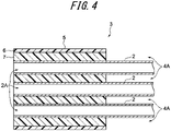
- the tubes 2 have respective interior spaces 2A (see Fig. 4 ) that are referred to as the first region.
- the second region is a space 4A outside the tubes 2.
- a liquid is supplied to the first region, while gas in the second region is suctioned.
- the degassing module 1 degasses the liquid by supplying the liquid into the interior spaces 2A (the first region) of respective tubes 2 and by suctioning gas in the space 4A outside the tubes 2 (the second region) .
- Each tube 2 is a tubular membrane that allows gas to pass but prohibits liquid from passing.
- the material of the tube 2 and the shape, type, or the like of the membrane are not specifically limited.
- the material of the tube 2 is fluororesin, polypropylene (PP), polymethylpentene (PMP), silicone, polyimide, or polyamide.
- fluororesin examples may be polytetrafluoroethylene (PTFE), tetrafluoroethylene-perfluoroalkyl vinyl ether copolymer (PFA), tetrafluoroethylene- hexafluoropropylene copolymer (FEP), tetrafluoroethylene-ethylene copolymer (ethylene copolymer)(ETFE), polychlorotrifluoroethylene (PCTFE), amorphous fluoropolymer (AF), and polyvinylidene fluoride (PVDF).
- PTFE polytetrafluoroethylene
- PFA tetrafluoroethylene-perfluoroalkyl vinyl ether copolymer
- FEP tetrafluoroethylene-hexafluoropropylene copolymer
- EFE tetrafluoroethylene-ethylene copolymer
- PCTFE polychlorotrifluoroethylene
- AF amorphous fluoropolymer
- Fig. 2 is a schematic perspective view illustrating an example of a tube unit
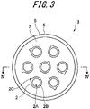
- Fig. 3 is a schematic end view illustrating the example of the tube unit
- Fig. 4 is a schematic cross-sectional view taken along line IV-IV in Fig. 3 .
- the tube unit 3 is formed by bundling the multiple tubes 2 at both ends thereof.
- the tube unit 3 includes the multiple tubes 2 and a pair of bundling portions 5 that bundle the tubes 2 at one ends and at opposite ends, respectively.
- a pair of the bundling portions 5 are portions to be attached to the housing 4.
- a pair of the bundling portions 5 are structured similarly to each other and accordingly the following description will focus on one of the bundling portions 5 as a representative example.
- Each bundling portion 5 includes an outer sheath 6 and a sealing portion 7.
- the outer sheath 6 is fitted around end portions of the tubes 2, and the sealing portion 7 is a filling that fills the space among the end portions of the tubes 2 and the outer sheath 6.
- the outer sheath 6 is formed substantially cylindrically and serves as the outermost layer of the bundling portion 5.
- the outer sheath 6 is a portion to be attached to the housing 4.
- the material of the outer sheath 6 is a fluororesin, such as PFA or PTFE.
- the sealing portion 7 fills the space among the end portions of the tubes 2 and the outer sheath 6.
- the sealing portion 7 thereby bundles the end portions of the tubes 2 and seals the space among the end portions of the tubes 2 and the outer sheath 6.
- the sealing portion 7 does not fill the interior spaces 2A of respective tubes 2, whereas the sealing portion 7 fills the space among the tubes 2 and the space between the tubes 2 and the outer sheath 6 (see Fig. 3 ).
- the material of the sealing portion 7 is a fluororesin, such as FEP or PFA.
- each one of the tubes 2 bundled by the sealing portion 7 has a tube wall portion 2B and a protrusion 2C that protrudes from the tube wall portion 2B.
- the tube wall portion 2B is shaped cylindrically and extends in the extension direction of the corresponding tube 2.
- the protrusion 2C is a portion that protrudes radially outward from the tube wall portion 2B.
- the protrusion 2C may be a thick wall portion (or a bulged portion) of the tube 2 or may be a curved portion formed as if part of the end portion of the tube 2 were pinched out.
- the wall of the end portion of the tube 2 is made thicker at the protrusion 2C.
- the end portion of the tube 2 may have one protrusion 2C.
- the end portion of the tube 2 may have multiple protrusions 2C.
- the protrusions 2C may be shaped similarly as illustrated in Fig. 5(b) , or the protrusions 2C may be shaped differently as illustrated in Fig. 5(c) .
- the protruding directions of the protrusions 2C at the end portions of respective tubes 2 may be arranged in an orderly manner or may be arranged in a non-orderly manner.
- the protrusion 2C may extend so as to have the same shape in the extension direction of the tube 2 or may have different shapes.
- the protrusion 2C may be formed over the entire length of the end portion in the extension direction of the tube 2 or may be formed partially or intermittently.
- the end portions of the tubes 2 may be arranged arbitrarily. For example, the end portions of the tubes 2 may be arranged such that the tube wall portions 2B form a fine structure and multiple protrusions 2C are present among the tube wall portions 2B.
- the protrusion 2C may be provided by using a tube 2 having a thick portion that is formed in advance so as to serve as the protrusion 2C.
- the protrusion 2C for each tube 2 may be formed by pinching part of the tube 2 using a tool. In this state, the sealing portion 7 fills the space among the outer sheath 6 and the end portions of the tubes 2 having such protrusions 2C.
- the housing 4 includes a housing body 11, a lid 12, a first connector 13, and a second connector 14.
- the housing body 11 is a portion that accommodates the tube unit 3.
- the housing body 11 is a cylindrically shaped container having an opening at one end.
- the lid 12 is joined to the housing body 11 in a gas-tight manner and closes the opening of the housing body 11.
- the lid 12 may be joined to the housing body 11 by welding, screw-fitting, or interfitting.
- the housing 4 may be formed integrally and the housing body 11 and the lid 12 may be inseparable, insofar as this does not cause any assembling problem.
- the first connector 13 and the second connector 14 are joined to the lid 12 in a gas-tight manner.
- a first opening 15 pierces the first connector 13 so as to communicate the inside and the outside of the lid 12 (the housing 4), and a second opening 16 pierces the second connector 14 so as to communicate the inside and the outside of the lid 12 (the housing 4).
- the first connector 13 and the second connector 14 may be joined to the lid 12 by welding, screw-fitting, or interfitting.
- the first connector 13 is joined gas-tightly to one of the bundling portions 5 of the tube unit 3.
- the first connector 13 thereby joins the one of the bundling portions 5 of the tube unit 3 gas-tightly to the housing.
- the first connector 13 is shaped like a cylinder having a step portion and is disposed between the one of the bundling portions 5 of the tube unit 3 and the housing 4.
- a first pipe 18 is connected to the first connector 13.
- the first pipe 18 is in communication with the interior spaces 2A of the tubes 2.
- the one of the bundling portions 5 of the tube unit 3 may be joined to the first connector 13 by welding, screw-fitting, or interfitting.
- the first pipe 18 may be joined to the first connector 13 by welding, screw-fitting, or interfitting.
- the second connector 14 is joined gas-tightly to the other one of the bundling portions 5 of the tube unit 3.
- the second connector 14 thereby joins the other one of the bundling portions 5 of the tube unit 3 gas-tightly to the housing.
- the second connector 14 is shaped like a cylinder having a step portion and is disposed between the other one of the bundling portions 5 of the tube unit 3 and the housing 4.
- a second pipe 19 is connected to the second connector 14.
- the second pipe 19 is in communication with the interior spaces 2A of the tubes 2.
- the other one of the bundling portions 5 of the tube unit 3 may be joined to the second connector 14 by welding, screw-fitting, or interfitting.
- the second pipe 19 may be joined to the second connector 14 by welding, screw-fitting, or interfitting.
- the housing body 11 has a suction port 20.
- the suction port 20 is an opening formed in the housing body 11, through which gas in the space 4A outside the tubes 2 and inside the housing 4 is suctioned.
- a third pipe 21 is connected to the suction port 20.
- the third pipe 21 is in communication with the space 4A outside the tubes 2 and inside the housing 4.
- a suction pump (not illustrated) is connected to the third pipe 21 to suction gas through the suction port 20, thereby depressurizing the space 4A outside the tubes 2 and inside the housing 4.
- the third pipe 21 may be joined to the suction port 20 by welding, screw-fitting, or interfitting.
- the degassing module 1 structured as described above degasses a liquid in the following manner: the liquid is supplied to the first pipe 18 and discharged from the second pipe 19 while the suction pump connected to the third pipe 21 suctions gas in the space 4A outside the tubes 2 and inside the housing 4.
- the liquid supplied to the first pipe 18 subsequently enters the interior spaces 2A of the tubes 2 through the first connector 13.
- the space 4A outside the tubes 2 and inside the housing 4 is in a depressurized state. Accordingly, dissolved gas or gas bubbles in the liquid are suctioned and pass through the walls of the tubes 2 into the space 4A outside the tubes 2 and inside the housing 4.
- the liquid is degassed. Consequently, the degassed liquid is discharged to the second pipe 19 from the second connector 14.
- the liquid may be supplied to the second pipe 19 and discharged from the first pipe 18.
- An example of a liquid to be degassed is an organic solvent or water.
- a tube unit 100 that does not have protrusions is described with reference to Fig. 6 as a comparative example.
- the tube unit 100 of the comparative example is structured such that the end portions of respective tubes 102 are formed only of cylindrical tube wall portions 102B that extend in the extension directions of the tubes 102, and the end portions of the tubes 102 do not have portions corresponding to the protrusions 2C of the present embodiment.
- the end portions of respective tubes 102 can be disposed densely by arranging the tube wall portions 102B so as to form a fine structure.
- the end portions of respective tubes 102 are not disposed in the space among the tube wall portions 102B.
- the end portions of respective tubes 2 have the protrusions 2C protruding radially outward. Accordingly, the end portions of respective tubes 2 can be disposed such that the tube wall portions 2B form a fine structure and the protrusions 2C are positioned among the tube wall portions 2B. Accordingly, the end portions of the tubes 2 can be arranged more densely compared with the tube unit 100 of the comparative example. Thus, the bundling strength of the tubes 2 can be improved.
- cylindrically shaped tube wall portion 2B extends in the extension direction of the tube, which can reduce the pressure loss of a fluid flowing through the tube.
- the sealing portion 7 fills the space among the end portions of the tubes 2 and the outer sheath 6, which reduces the likelihood of the liquid leaking out among the tubes 2 when a fluid, such as a liquid or a gas, is supplied to the end face of the bundling portion 5.
- a fluid such as a liquid or a gas
- the end portions of respective tubes 2 are spaced from each other, and the end portions are thereby covered with the sealing portion 7. This can reduce the likelihood of the fluid leaking out at the interfaces of the end portions of the tubes 2.
- the liquid is supplied to the first opening 15 and is discharged from the second opening 16 while gas is suctioned from the suction port 20.
- the liquid supplied to the first opening 15 is degassed while flowing through the tubes 2 and is discharged from the second opening 16.
- the tube unit 3 configured as described above improves the bundling strength of the tubes 2. This can improve the durability of the degassing module 1 while reducing the likelihood that the liquid supplied to the first opening 15 leaks out into the space 4A outside the tubes 2.
- the tube unit has been described as the one having seven tubes, but the number of the tubes of the tube unit is not specifically limited.
- the tube unit may have several tens or several hundreds of tubes.
- the end portions of respective tubes have the protrusions.
- all of the end portions of the tubes need not have the tube wall portions and the protrusions, and it is sufficient that at least one of the end portions of respective tubes has a tube wall portion and a protrusion. Even with this configuration, the end portions of the tubes can be arranged densely and the bundling strength of the tubes can be improved.
- the cylindrically shaped tube wall portion extends in the extension direction of the tube.
- the tube wall portion may have an arbitrary shape insofar as the tube wall portion tubularly extends in the extension direction of each tube.
- the tube wall portion may be shaped like a tube having an oval section or having a hexagonal section. Even in the case of the tube wall portion being shaped as such, the tube wall portions have the protrusions protruding therefrom, which enables the end portions of the tubes to be disposed densely and can improve the bundling strength of the tubes.
- the sealing portion does not necessarily seal the space among the end portions of the tubes and the outer sheath if the tube unit of the present invention is not applied to the above-described degassing module but applied as other types of tube units.
Landscapes
- Engineering & Computer Science (AREA)
- Chemical & Material Sciences (AREA)
- Chemical Kinetics & Catalysis (AREA)
- General Engineering & Computer Science (AREA)
- Mechanical Engineering (AREA)
- Water Supply & Treatment (AREA)
- Separation Using Semi-Permeable Membranes (AREA)
- Degasification And Air Bubble Elimination (AREA)
- Rigid Pipes And Flexible Pipes (AREA)
Abstract
Description
- The present invention relates to a tube unit in which multiple tubes are bundled at both ends and also to a degassing module that includes the tube unit.
- PTL 1 below describes a bundle of fluororesin tubes in which end portions of respective tubes are bundled together. The bundle of fluororesin tubes includes bundled fluororesin tubes, a fluororesin sleeve fitted around each end portion of the bundle of fluororesin tubes, and a connection portion that is made of a thermally fluidizing fluororesin and that integrally joins the fluororesin sleeve to the fluororesin tubes. Each end portion of the fluororesin tubes is shaped cylindrically.
- PTL 1:
Japanese Unexamined Patent Application Publication No. 1-131392 - In the bundling structure in which the end portions of respective tubes are bundled, the bundling strength increases as the end portions of the tubes are bundled more densely. In the bundle of the fluororesin tubes described in PTL 1, the end portions of respective fluororesin tubes are each shaped cylindrically, which limits the degree of density of the end portions when the end portions are arranged to form a fine structure. This imposes a limit on the improvement of the bundling strength when the end portions of the fluororesin tubes are bundled.
- An object of one aspect of the present invention is to provide a tube unit and a degassing module with which the bundling strength of the tubes can be improved.
- A tube unit according to an aspect of the present invention includes multiple tubes and bundling portions that bundle end portions of respective tubes at opposite ends of the tubes. At least one of the end portions of respective tubes has a tube wall portion that tubularly extends in an extension direction of the tubes and also has a protrusion protruding radially outward from the tube wall portion.
- In this tube unit, at least one of the end portions of respective tubes has a protrusion protruding radially outward. Accordingly, protrusions can be disposed, for example, in the space among the tube wall portions and tubes adjacent to the tube wall portions. Accordingly, the end portions of respective tubes can be arranged more densely compared with the case in which the end portions do not have the protrusions. This can improve the bundling strength of the tubes.
- Each of the end portions of respective tubes may have the tube wall portion and the protrusion. In the tube unit, each of the end portions of respective tubes has the tube wall portion and the protrusion. This enables the protrusions to be positioned among the tube wall portions while, for example, the tube wall portions are disposed so as to form a fine structure. Accordingly, the end portions of the tubes can be disposed more densely, which can improve the bundling strength of the tubes.
- The tube wall portion may cylindrically extend in the extension direction of the tubes. In the tube unit, the tube wall portion cylindrically extends in the extension direction of the tubes, which can reduce the pressure loss of a fluid flowing through the tubes.
- Each bundling portion may have an outer sheath fitted around the tubes and a sealing portion that fills a space among the end portions of respective tubes and the outer sheath. In the tube unit, the sealing portion fills the space among the end portions of the tubes and the outer sheath, which reduces the likelihood of the liquid leaking out among the tubes when a fluid, such as a liquid or a gas, is supplied to the end face of the bundling portion.
- The end portions of respective tubes may be spaced from each other. In the tube unit, the end portions of respective tubes are spaced from each other, and the end portions are thereby covered with the sealing portion. This can reduce the likelihood of the fluid leaking out at the interfaces of the end portions of the tubes.
- A degassing module according to another aspect of the present invention includes any one of the tube units described above and a housing in which the tube unit is accommodated. Each of the tubes is a tubular membrane that allows gas to pass and prohibits liquid from passing. In addition, the housing has a first opening and a second opening both of which are in communication with interior spaces of respective tubes. The housing also has a suction port being in communication with a space outside the tubes.
- In the degassing module, a liquid is supplied to the first opening and is discharged from the second opening while gas is suctioned from the suction port. The liquid supplied to the first opening is degassed while flowing through the tubes and is discharged from the second opening. The degassing module includes the above-described tube unit that improves the bundling strength of the tubes. This can improve the durability of the degassing module while reducing the likelihood that the liquid supplied to the first opening leaks out into the space outside the tubes. Advantageous Effects of Invention
- According to an aspect of the present invention, the bundling strength of the tubes can be improved.
-
- [
Fig. 1] Fig. 1 is a schematic cross-sectional view illustrating an example of a degassing module. - [
Fig. 2] Fig. 2 is a schematic perspective view illustrating an example of a tube unit. - [
Fig. 3] Fig. 3 is a schematic end view illustrating an example of the tube unit. - [
Fig. 4] Fig. 4 is a schematic cross-sectional view taken along line IV-IV inFig. 3 . - [
Figs. 5] Fig. 5(a), Fig. 5(b), and Fig. 5(c) are schematic cross-sectional views illustrating examples of tubes. - [
Fig. 6] Fig. 6 is a schematic end view illustrating a tube unit of a comparative example. - A tube unit and a degassing module according to an embodiment will be described with reference to the drawings. Note that the same or equivalent elements will be denoted by the same reference signs in the drawings and duplicated descriptions will be omitted.
-
Fig. 1 is a schematic cross-sectional view illustrating an example of a degassing module. As illustrated inFig. 1 , a degassing module 1 includes atube unit 3 in whichmultiple tubes 2 are bundled at both ends and also includes ahousing 4 that accommodates thetube unit 3. The degassing module 1 has a first region and a second region in thehousing 4. Thetubes 2 have respectiveinterior spaces 2A (seeFig. 4 ) that are referred to as the first region. The second region is aspace 4A outside thetubes 2. A liquid is supplied to the first region, while gas in the second region is suctioned. The degassing module 1 degasses the liquid by supplying the liquid into theinterior spaces 2A (the first region) ofrespective tubes 2 and by suctioning gas in thespace 4A outside the tubes 2 (the second region) . - Each
tube 2 is a tubular membrane that allows gas to pass but prohibits liquid from passing. The material of thetube 2 and the shape, type, or the like of the membrane are not specifically limited. For example, the material of thetube 2 is fluororesin, polypropylene (PP), polymethylpentene (PMP), silicone, polyimide, or polyamide. Examples of the fluororesin may be polytetrafluoroethylene (PTFE), tetrafluoroethylene-perfluoroalkyl vinyl ether copolymer (PFA), tetrafluoroethylene- hexafluoropropylene copolymer (FEP), tetrafluoroethylene-ethylene copolymer (ethylene copolymer)(ETFE), polychlorotrifluoroethylene (PCTFE), amorphous fluoropolymer (AF), and polyvinylidene fluoride (PVDF). An example of the amorphous fluoropolymer may be Teflon® AF. -
Fig. 2 is a schematic perspective view illustrating an example of a tube unit, andFig. 3 is a schematic end view illustrating the example of the tube unit.Fig. 4 is a schematic cross-sectional view taken along line IV-IV inFig. 3 . Note that these figures illustrate an example of atube unit 3 that includes seventubes 2. The number of thetubes 2, however, is not specifically limited. As illustrated inFigs. 2 to 4 , thetube unit 3 is formed by bundling themultiple tubes 2 at both ends thereof. In other words, thetube unit 3 includes themultiple tubes 2 and a pair of bundlingportions 5 that bundle thetubes 2 at one ends and at opposite ends, respectively. A pair of thebundling portions 5 are portions to be attached to thehousing 4. Note that a pair of thebundling portions 5 are structured similarly to each other and accordingly the following description will focus on one of thebundling portions 5 as a representative example. A pair of thebundling portions 5, however, may be structured differently. - Each bundling
portion 5 includes anouter sheath 6 and a sealingportion 7. Theouter sheath 6 is fitted around end portions of thetubes 2, and the sealingportion 7 is a filling that fills the space among the end portions of thetubes 2 and theouter sheath 6. - The
outer sheath 6 is formed substantially cylindrically and serves as the outermost layer of the bundlingportion 5. Theouter sheath 6 is a portion to be attached to thehousing 4. For example, the material of theouter sheath 6 is a fluororesin, such as PFA or PTFE. - The sealing
portion 7 fills the space among the end portions of thetubes 2 and theouter sheath 6. The sealingportion 7 thereby bundles the end portions of thetubes 2 and seals the space among the end portions of thetubes 2 and theouter sheath 6. In other words, the sealingportion 7 does not fill theinterior spaces 2A ofrespective tubes 2, whereas the sealingportion 7 fills the space among thetubes 2 and the space between thetubes 2 and the outer sheath 6 (seeFig. 3 ). When the end face of the sealingportion 7 is viewed, only theinterior spaces 2A of thetubes 2 are open. For example, the material of the sealingportion 7 is a fluororesin, such as FEP or PFA. - An end portion of each one of the
tubes 2 bundled by the sealingportion 7 has atube wall portion 2B and aprotrusion 2C that protrudes from thetube wall portion 2B. Thetube wall portion 2B is shaped cylindrically and extends in the extension direction of thecorresponding tube 2. Theprotrusion 2C is a portion that protrudes radially outward from thetube wall portion 2B. For example, theprotrusion 2C may be a thick wall portion (or a bulged portion) of thetube 2 or may be a curved portion formed as if part of the end portion of thetube 2 were pinched out. For example, the wall of the end portion of thetube 2 is made thicker at theprotrusion 2C. - As illustrated in
Fig. 5(a) , the end portion of thetube 2 may have oneprotrusion 2C. Alternatively, as illustrated inFig. 5(b) and Fig. 5(c) , the end portion of thetube 2 may havemultiple protrusions 2C. In the case of thetube 2 havingmultiple protrusions 2C, theprotrusions 2C may be shaped similarly as illustrated inFig. 5(b) , or theprotrusions 2C may be shaped differently as illustrated inFig. 5(c) . - The protruding directions of the
protrusions 2C at the end portions ofrespective tubes 2 may be arranged in an orderly manner or may be arranged in a non-orderly manner. Theprotrusion 2C may extend so as to have the same shape in the extension direction of thetube 2 or may have different shapes. Theprotrusion 2C may be formed over the entire length of the end portion in the extension direction of thetube 2 or may be formed partially or intermittently. The end portions of thetubes 2 may be arranged arbitrarily. For example, the end portions of thetubes 2 may be arranged such that thetube wall portions 2B form a fine structure andmultiple protrusions 2C are present among thetube wall portions 2B. - For example, the
protrusion 2C may be provided by using atube 2 having a thick portion that is formed in advance so as to serve as theprotrusion 2C. Alternatively, for example, theprotrusion 2C for eachtube 2 may be formed by pinching part of thetube 2 using a tool. In this state, the sealingportion 7 fills the space among theouter sheath 6 and the end portions of thetubes 2 havingsuch protrusions 2C. - As illustrated in
Fig. 1 , thehousing 4 includes ahousing body 11, alid 12, afirst connector 13, and asecond connector 14. - The
housing body 11 is a portion that accommodates thetube unit 3. Thehousing body 11 is a cylindrically shaped container having an opening at one end. Thelid 12 is joined to thehousing body 11 in a gas-tight manner and closes the opening of thehousing body 11. For example, thelid 12 may be joined to thehousing body 11 by welding, screw-fitting, or interfitting. Thehousing 4 may be formed integrally and thehousing body 11 and thelid 12 may be inseparable, insofar as this does not cause any assembling problem. - The
first connector 13 and thesecond connector 14 are joined to thelid 12 in a gas-tight manner. Afirst opening 15 pierces thefirst connector 13 so as to communicate the inside and the outside of the lid 12 (the housing 4), and asecond opening 16 pierces thesecond connector 14 so as to communicate the inside and the outside of the lid 12 (the housing 4). For example, thefirst connector 13 and thesecond connector 14 may be joined to thelid 12 by welding, screw-fitting, or interfitting. - The
first connector 13 is joined gas-tightly to one of thebundling portions 5 of thetube unit 3. Thefirst connector 13 thereby joins the one of thebundling portions 5 of thetube unit 3 gas-tightly to the housing. For example, thefirst connector 13 is shaped like a cylinder having a step portion and is disposed between the one of thebundling portions 5 of thetube unit 3 and thehousing 4. Afirst pipe 18 is connected to thefirst connector 13. Thefirst pipe 18 is in communication with theinterior spaces 2A of thetubes 2. For example, the one of thebundling portions 5 of thetube unit 3 may be joined to thefirst connector 13 by welding, screw-fitting, or interfitting. For example, thefirst pipe 18 may be joined to thefirst connector 13 by welding, screw-fitting, or interfitting. - The
second connector 14 is joined gas-tightly to the other one of thebundling portions 5 of thetube unit 3. Thesecond connector 14 thereby joins the other one of thebundling portions 5 of thetube unit 3 gas-tightly to the housing. For example, thesecond connector 14 is shaped like a cylinder having a step portion and is disposed between the other one of thebundling portions 5 of thetube unit 3 and thehousing 4. Asecond pipe 19 is connected to thesecond connector 14. Thesecond pipe 19 is in communication with theinterior spaces 2A of thetubes 2. For example, the other one of thebundling portions 5 of thetube unit 3 may be joined to thesecond connector 14 by welding, screw-fitting, or interfitting. For example, thesecond pipe 19 may be joined to thesecond connector 14 by welding, screw-fitting, or interfitting. - The
housing body 11 has asuction port 20. Thesuction port 20 is an opening formed in thehousing body 11, through which gas in thespace 4A outside thetubes 2 and inside thehousing 4 is suctioned. Athird pipe 21 is connected to thesuction port 20. Thethird pipe 21 is in communication with thespace 4A outside thetubes 2 and inside thehousing 4. A suction pump (not illustrated) is connected to thethird pipe 21 to suction gas through thesuction port 20, thereby depressurizing thespace 4A outside thetubes 2 and inside thehousing 4. Thethird pipe 21 may be joined to thesuction port 20 by welding, screw-fitting, or interfitting. - The degassing module 1 structured as described above degasses a liquid in the following manner: the liquid is supplied to the
first pipe 18 and discharged from thesecond pipe 19 while the suction pump connected to thethird pipe 21 suctions gas in thespace 4A outside thetubes 2 and inside thehousing 4. The liquid supplied to thefirst pipe 18 subsequently enters theinterior spaces 2A of thetubes 2 through thefirst connector 13. When the liquid flows through theinterior spaces 2A of thetubes 2, thespace 4A outside thetubes 2 and inside thehousing 4 is in a depressurized state. Accordingly, dissolved gas or gas bubbles in the liquid are suctioned and pass through the walls of thetubes 2 into thespace 4A outside thetubes 2 and inside thehousing 4. Thus, the liquid is degassed. Consequently, the degassed liquid is discharged to thesecond pipe 19 from thesecond connector 14. Note that the liquid may be supplied to thesecond pipe 19 and discharged from thefirst pipe 18. - An example of a liquid to be degassed is an organic solvent or water.
- Here, a
tube unit 100 that does not have protrusions is described with reference toFig. 6 as a comparative example. - As illustrated in
Fig. 6 , thetube unit 100 of the comparative example is structured such that the end portions ofrespective tubes 102 are formed only of cylindricaltube wall portions 102B that extend in the extension directions of thetubes 102, and the end portions of thetubes 102 do not have portions corresponding to theprotrusions 2C of the present embodiment. The end portions ofrespective tubes 102 can be disposed densely by arranging thetube wall portions 102B so as to form a fine structure. The end portions ofrespective tubes 102, however, are not disposed in the space among thetube wall portions 102B. - On the other hand, in the
tube unit 3 according to the present embodiment, the end portions ofrespective tubes 2 have theprotrusions 2C protruding radially outward. Accordingly, the end portions ofrespective tubes 2 can be disposed such that thetube wall portions 2B form a fine structure and theprotrusions 2C are positioned among thetube wall portions 2B. Accordingly, the end portions of thetubes 2 can be arranged more densely compared with thetube unit 100 of the comparative example. Thus, the bundling strength of thetubes 2 can be improved. - In addition, the cylindrically shaped
tube wall portion 2B extends in the extension direction of the tube, which can reduce the pressure loss of a fluid flowing through the tube. - The sealing
portion 7 fills the space among the end portions of thetubes 2 and theouter sheath 6, which reduces the likelihood of the liquid leaking out among thetubes 2 when a fluid, such as a liquid or a gas, is supplied to the end face of the bundlingportion 5. In other words, when a liquid is supplied to thefirst pipe 18, the liquid is supplied only to theinterior spaces 2A of thetubes 2. The likelihood of the liquid leaking out into thespace 4A outside thetubes 2 and inside thehousing 4 can be reduced. - The end portions of
respective tubes 2 are spaced from each other, and the end portions are thereby covered with the sealingportion 7. This can reduce the likelihood of the fluid leaking out at the interfaces of the end portions of thetubes 2. - In the degassing module 1 of the present embodiment, the liquid is supplied to the
first opening 15 and is discharged from thesecond opening 16 while gas is suctioned from thesuction port 20. The liquid supplied to thefirst opening 15 is degassed while flowing through thetubes 2 and is discharged from thesecond opening 16. Thetube unit 3 configured as described above improves the bundling strength of thetubes 2. This can improve the durability of the degassing module 1 while reducing the likelihood that the liquid supplied to thefirst opening 15 leaks out into thespace 4A outside thetubes 2. - One embodiment of the present invention has been described. The present invention, however, is not limited to the above embodiment.
- For example, in the above embodiment, the tube unit has been described as the one having seven tubes, but the number of the tubes of the tube unit is not specifically limited. For example, the tube unit may have several tens or several hundreds of tubes.
- In addition, it has been described in the above embodiment that the end portions of respective tubes have the protrusions. However, all of the end portions of the tubes need not have the tube wall portions and the protrusions, and it is sufficient that at least one of the end portions of respective tubes has a tube wall portion and a protrusion. Even with this configuration, the end portions of the tubes can be arranged densely and the bundling strength of the tubes can be improved.
- Moreover, it has been described in the above embodiment that the cylindrically shaped tube wall portion extends in the extension direction of the tube. The tube wall portion, however, may have an arbitrary shape insofar as the tube wall portion tubularly extends in the extension direction of each tube. For example, the tube wall portion may be shaped like a tube having an oval section or having a hexagonal section. Even in the case of the tube wall portion being shaped as such, the tube wall portions have the protrusions protruding therefrom, which enables the end portions of the tubes to be disposed densely and can improve the bundling strength of the tubes.
- The sealing portion does not necessarily seal the space among the end portions of the tubes and the outer sheath if the tube unit of the present invention is not applied to the above-described degassing module but applied as other types of tube units.
-
- 1
- degassing module
- 2
- tube
- 2A
- interior space
- 2B
- tube wall portion
- 2C
- protrusion
- 3
- tube unit
- 4
- housing
- 4A
- space
- 5
- bundling portion
- 6
- outer sheath
- 7
- sealing portion
- 12
- lid
- 13
- first connector
- 14
- second connector
- 15
- first opening
- 16
- second opening
- 18
- first pipe
- 19
- second pipe
- 20
- suction port
- 21
- third pipe
- 100
- tube unit
- 102
- tube
- 102B
- tube wall portion
Claims (6)
- A tube unit comprising:multiple tubes; andbundling portions that bundle end portions of respective tubes at opposite ends of the tubes, whereinat least one of the end portions of respective tubes hasa tube wall portion that tubularly extends in an extension direction of the tubes anda protrusion protruding radially outward from the tube wall portion.
- The tube unit according to Claim 1, wherein
each of the end portions of respective tubes has the tube wall portion and the protrusion. - The tube unit according to Claim 1 or 2, wherein
the tube wall portion cylindrically extends in the extension direction of the tubes. - The tube unit according to any one of Claims 1 to 3, whereineach one of the bundling portions has an outer sheath fitted around the tubes, anda sealing portion that fills a space among the end portions of respective tubes and the outer sheath.
- The tube unit according to Claim 4, wherein
the end portions of respective tubes are spaced from each other. - A degassing module comprising:the tube unit according to any one of Claims 1 to 5; anda housing in which the tube unit is accommodated, whereineach of the tubes is a tubular membrane that allows gas to pass and prohibits liquid from passing, andthe housing hasa first opening and a second opening both of which are in communication with interior spaces of respective tubes, anda suction port being in communication with a space outside the tubes.
Applications Claiming Priority (2)
| Application Number | Priority Date | Filing Date | Title |
|---|---|---|---|
| JP2019148514 | 2019-08-13 | ||
| PCT/JP2020/030627 WO2021029415A1 (en) | 2019-08-13 | 2020-08-11 | Tube unit and degassing module |
Publications (3)
| Publication Number | Publication Date |
|---|---|
| EP4015886A1 true EP4015886A1 (en) | 2022-06-22 |
| EP4015886A4 EP4015886A4 (en) | 2023-03-15 |
| EP4015886B1 EP4015886B1 (en) | 2024-09-25 |
Family
ID=74570353
Family Applications (1)
| Application Number | Title | Priority Date | Filing Date |
|---|---|---|---|
| EP20853304.2A Active EP4015886B1 (en) | 2019-08-13 | 2020-08-11 | Degassing module |
Country Status (7)
| Country | Link |
|---|---|
| US (1) | US12090445B2 (en) |
| EP (1) | EP4015886B1 (en) |
| JP (1) | JP7040675B2 (en) |
| KR (1) | KR102669011B1 (en) |
| CN (1) | CN114206479B (en) |
| TW (1) | TWI875796B (en) |
| WO (1) | WO2021029415A1 (en) |
Families Citing this family (2)
| Publication number | Priority date | Publication date | Assignee | Title |
|---|---|---|---|---|
| JPWO2024101435A1 (en) * | 2022-11-11 | 2024-05-16 | ||
| JPWO2025177744A1 (en) * | 2024-02-22 | 2025-08-28 |
Family Cites Families (29)
| Publication number | Priority date | Publication date | Assignee | Title |
|---|---|---|---|---|
| JPS61268304A (en) * | 1984-11-16 | 1986-11-27 | Teijin Ltd | Fluid separator |
| JPH01131392A (en) | 1987-11-12 | 1989-05-24 | Junkosha Co Ltd | Fluoroplastic tube bundle and manufacture thereof |
| JP2780331B2 (en) * | 1989-04-28 | 1998-07-30 | 日東電工株式会社 | Liquid degassing method |
| US5002657A (en) * | 1990-05-04 | 1991-03-26 | Botts John B | Separator for oil well production fluids |
| JP3398825B2 (en) * | 1994-10-17 | 2003-04-21 | 日東電工株式会社 | Degassing device |
| JP3398824B2 (en) * | 1994-10-17 | 2003-04-21 | 日東電工株式会社 | Degassing device |
| AU2004203855B2 (en) * | 1995-08-11 | 2006-06-29 | Ge Betzdearborn Canada Company | Vertical skein of hollow fiber membranes and method of maintaining clean fiber surfaces |
| JPH1057946A (en) * | 1996-08-22 | 1998-03-03 | Nitto Denko Corp | Degassing device |
| JP2001079331A (en) * | 1999-07-09 | 2001-03-27 | Kyocera Corp | Gas separation module |
| JP2001129368A (en) * | 1999-08-20 | 2001-05-15 | Herushii Techno Chem:Kk | Gas-liquid separation module |
| US6228146B1 (en) * | 2000-03-03 | 2001-05-08 | Don R. Kuespert | Gas recovery device |
| JP2002130548A (en) * | 2000-10-23 | 2002-05-09 | Matsushita Electric Works Ltd | Flexible hose |
| US7255729B2 (en) * | 2003-05-30 | 2007-08-14 | Noritake Co., Limited | Porous cylindrical-body module, structure for supporting porous cylindrical bodies, and method for fastening a supporting member |
| JP4194905B2 (en) * | 2003-08-18 | 2008-12-10 | 株式会社ノリタケカンパニーリミテド | Support structure for porous cylinder and fixing method for support member |
| DE102004004212B4 (en) * | 2004-01-27 | 2007-02-08 | Koch Membrane Systems Gmbh | Membrane filter unit and method of making the membrane filter unit |
| JP2007209966A (en) * | 2006-02-09 | 2007-08-23 | Satako:Kk | Gas separation device |
| JP2010264405A (en) | 2009-05-15 | 2010-11-25 | Nitto Denko Corp | Deaerator |
| JP5890981B2 (en) * | 2011-08-19 | 2016-03-22 | 日立造船株式会社 | Separation membrane module |
| US9061251B2 (en) * | 2011-09-27 | 2015-06-23 | Markel Corporation | Self sealing membrane contactor with PTFE tubular membranes |
| JP5708619B2 (en) * | 2012-11-26 | 2015-04-30 | Nok株式会社 | Hollow fiber membrane module |
| JP2015016400A (en) * | 2013-07-09 | 2015-01-29 | 三菱レイヨン株式会社 | Hollow fiber membrane and hollow fiber membrane module for deaeration |
| JP2015029927A (en) * | 2013-07-31 | 2015-02-16 | 三菱レイヨン株式会社 | Hollow fiber membrane, method for producing the same, and hollow fiber membrane module |
| JP2016036755A (en) * | 2014-08-06 | 2016-03-22 | Nok株式会社 | Hollow fiber membrane module of porous ceramic |
| JP6439560B2 (en) * | 2015-04-09 | 2018-12-19 | Nok株式会社 | Hollow fiber membrane cartridge |
| CN204855886U (en) * | 2015-06-17 | 2015-12-09 | 顾琪超 | Be used for open air heat -resisting optical cable of high strength of easily binding |
| CA3023277C (en) * | 2016-06-30 | 2020-11-10 | Dic Corporation | Hollow fiber degassing module, and method of degassing liquid using said hollow fiber degassing module |
| CN109562327B (en) * | 2016-08-17 | 2022-06-03 | 三菱化学可菱水株式会社 | Hollow fiber membrane module, degassing and gas supply device, inkjet printer, and carbonated spring manufacturing device |
| JP2018153715A (en) | 2017-03-15 | 2018-10-04 | 三菱ケミカル株式会社 | Separation membrane module |
| JP2019181356A (en) | 2018-04-06 | 2019-10-24 | 三菱ケミカル株式会社 | External perfusion type hollow fiber membrane module |
-
2020
- 2020-08-11 KR KR1020227001585A patent/KR102669011B1/en active Active
- 2020-08-11 EP EP20853304.2A patent/EP4015886B1/en active Active
- 2020-08-11 CN CN202080056701.0A patent/CN114206479B/en active Active
- 2020-08-11 WO PCT/JP2020/030627 patent/WO2021029415A1/en not_active Ceased
- 2020-08-11 US US17/634,243 patent/US12090445B2/en active Active
- 2020-08-11 JP JP2021535982A patent/JP7040675B2/en active Active
- 2020-08-12 TW TW109127301A patent/TWI875796B/en active
Also Published As
| Publication number | Publication date |
|---|---|
| JPWO2021029415A1 (en) | 2021-12-02 |
| US12090445B2 (en) | 2024-09-17 |
| US20220331713A1 (en) | 2022-10-20 |
| JP7040675B2 (en) | 2022-03-23 |
| CN114206479A (en) | 2022-03-18 |
| KR102669011B1 (en) | 2024-05-27 |
| KR20220020968A (en) | 2022-02-21 |
| WO2021029415A1 (en) | 2021-02-18 |
| EP4015886A4 (en) | 2023-03-15 |
| CN114206479B (en) | 2024-03-22 |
| TWI875796B (en) | 2025-03-11 |
| EP4015886B1 (en) | 2024-09-25 |
| TW202120845A (en) | 2021-06-01 |
Similar Documents
| Publication | Publication Date | Title |
|---|---|---|
| US12178984B2 (en) | Infusion tube system and method for manufacture | |
| EP4015886B1 (en) | Degassing module | |
| US20260034479A1 (en) | Tube unit, degassing module, and method of manufacturing tube unit | |
| US20220062794A1 (en) | Degassing system, method for degassing liquids, degassing unit, degassing module, and degassing-system manufacturing method and method of production from natural resources | |
| US7686867B2 (en) | Degasifier | |
| AU2019346723B2 (en) | Degasification system, liquid degasification method, degasification module, method for manufacturing degasification system, and method for producing natural resources | |
| EP4617537A1 (en) | Tube unit, deaeration module, and method for producing tube unit | |
| EP3434348B1 (en) | Fluid degassing devices having selected profiles | |
| JP2006082036A (en) | Hollow fiber membrane module | |
| WO2025177744A1 (en) | Tube unit, deaeration module, and deaeration method | |
| CN111556765B (en) | Artificial lung and its manufacturing method | |
| WO2026058676A1 (en) | Tube unit and deaeration module | |
| TWI921341B (en) | Manufacturing method of pipe unit, degassing module and pipe unit | |
| JP4105716B2 (en) | Deaeration device and deaeration method | |
| CN214887531U (en) | Piston type leak-free sample injector for corrosive solution | |
| EP4375555B1 (en) | Connecting tube, electrolysis system and connection method | |
| EP4268919A1 (en) | Deaerator |
Legal Events
| Date | Code | Title | Description |
|---|---|---|---|
| STAA | Information on the status of an ep patent application or granted ep patent |
Free format text: STATUS: THE INTERNATIONAL PUBLICATION HAS BEEN MADE |
|
| PUAI | Public reference made under article 153(3) epc to a published international application that has entered the european phase |
Free format text: ORIGINAL CODE: 0009012 |
|
| STAA | Information on the status of an ep patent application or granted ep patent |
Free format text: STATUS: REQUEST FOR EXAMINATION WAS MADE |
|
| 17P | Request for examination filed |
Effective date: 20220210 |
|
| AK | Designated contracting states |
Kind code of ref document: A1 Designated state(s): AL AT BE BG CH CY CZ DE DK EE ES FI FR GB GR HR HU IE IS IT LI LT LU LV MC MK MT NL NO PL PT RO RS SE SI SK SM TR |
|
| DAV | Request for validation of the european patent (deleted) | ||
| DAX | Request for extension of the european patent (deleted) | ||
| A4 | Supplementary search report drawn up and despatched |
Effective date: 20230209 |
|
| RIC1 | Information provided on ipc code assigned before grant |
Ipc: B01D 63/06 20060101ALI20230203BHEP Ipc: B01D 61/00 20060101ALI20230203BHEP Ipc: B01D 19/00 20060101ALI20230203BHEP Ipc: F16L 9/19 20060101AFI20230203BHEP |
|
| STAA | Information on the status of an ep patent application or granted ep patent |
Free format text: STATUS: EXAMINATION IS IN PROGRESS |
|
| 17Q | First examination report despatched |
Effective date: 20231208 |
|
| GRAP | Despatch of communication of intention to grant a patent |
Free format text: ORIGINAL CODE: EPIDOSNIGR1 |
|
| STAA | Information on the status of an ep patent application or granted ep patent |
Free format text: STATUS: GRANT OF PATENT IS INTENDED |
|
| INTG | Intention to grant announced |
Effective date: 20240502 |
|
| RIN1 | Information on inventor provided before grant (corrected) |
Inventor name: OI, KAZUMI Inventor name: SATO, AKIRA Inventor name: KAWASHIMA, KAZUYASU Inventor name: SUGANUMA, YOUHEI |
|
| GRAJ | Information related to disapproval of communication of intention to grant by the applicant or resumption of examination proceedings by the epo deleted |
Free format text: ORIGINAL CODE: EPIDOSDIGR1 |
|
| STAA | Information on the status of an ep patent application or granted ep patent |
Free format text: STATUS: EXAMINATION IS IN PROGRESS |
|
| GRAP | Despatch of communication of intention to grant a patent |
Free format text: ORIGINAL CODE: EPIDOSNIGR1 |
|
| STAA | Information on the status of an ep patent application or granted ep patent |
Free format text: STATUS: GRANT OF PATENT IS INTENDED |
|
| INTC | Intention to grant announced (deleted) | ||
| INTG | Intention to grant announced |
Effective date: 20240626 |
|
| GRAS | Grant fee paid |
Free format text: ORIGINAL CODE: EPIDOSNIGR3 |
|
| GRAA | (expected) grant |
Free format text: ORIGINAL CODE: 0009210 |
|
| STAA | Information on the status of an ep patent application or granted ep patent |
Free format text: STATUS: THE PATENT HAS BEEN GRANTED |
|
| AK | Designated contracting states |
Kind code of ref document: B1 Designated state(s): AL AT BE BG CH CY CZ DE DK EE ES FI FR GB GR HR HU IE IS IT LI LT LU LV MC MK MT NL NO PL PT RO RS SE SI SK SM TR |
|
| P01 | Opt-out of the competence of the unified patent court (upc) registered |
Free format text: CASE NUMBER: APP_47944/2024 Effective date: 20240821 |
|
| REG | Reference to a national code |
Ref country code: GB Ref legal event code: FG4D |
|
| REG | Reference to a national code |
Ref country code: CH Ref legal event code: EP |
|
| REG | Reference to a national code |
Ref country code: DE Ref legal event code: R096 Ref document number: 602020038467 Country of ref document: DE |
|
| REG | Reference to a national code |
Ref country code: IE Ref legal event code: FG4D |
|
| REG | Reference to a national code |
Ref country code: LT Ref legal event code: MG9D |
|
| PG25 | Lapsed in a contracting state [announced via postgrant information from national office to epo] |
Ref country code: NO Free format text: LAPSE BECAUSE OF FAILURE TO SUBMIT A TRANSLATION OF THE DESCRIPTION OR TO PAY THE FEE WITHIN THE PRESCRIBED TIME-LIMIT Effective date: 20241225 |
|
| PG25 | Lapsed in a contracting state [announced via postgrant information from national office to epo] |
Ref country code: GR Free format text: LAPSE BECAUSE OF FAILURE TO SUBMIT A TRANSLATION OF THE DESCRIPTION OR TO PAY THE FEE WITHIN THE PRESCRIBED TIME-LIMIT Effective date: 20241226 Ref country code: FI Free format text: LAPSE BECAUSE OF FAILURE TO SUBMIT A TRANSLATION OF THE DESCRIPTION OR TO PAY THE FEE WITHIN THE PRESCRIBED TIME-LIMIT Effective date: 20240925 |
|
| PG25 | Lapsed in a contracting state [announced via postgrant information from national office to epo] |
Ref country code: BG Free format text: LAPSE BECAUSE OF FAILURE TO SUBMIT A TRANSLATION OF THE DESCRIPTION OR TO PAY THE FEE WITHIN THE PRESCRIBED TIME-LIMIT Effective date: 20240925 |
|
| PG25 | Lapsed in a contracting state [announced via postgrant information from national office to epo] |
Ref country code: LV Free format text: LAPSE BECAUSE OF FAILURE TO SUBMIT A TRANSLATION OF THE DESCRIPTION OR TO PAY THE FEE WITHIN THE PRESCRIBED TIME-LIMIT Effective date: 20240925 |
|
| PG25 | Lapsed in a contracting state [announced via postgrant information from national office to epo] |
Ref country code: RS Free format text: LAPSE BECAUSE OF FAILURE TO SUBMIT A TRANSLATION OF THE DESCRIPTION OR TO PAY THE FEE WITHIN THE PRESCRIBED TIME-LIMIT Effective date: 20241225 |
|
| REG | Reference to a national code |
Ref country code: NL Ref legal event code: MP Effective date: 20240925 |
|
| PG25 | Lapsed in a contracting state [announced via postgrant information from national office to epo] |
Ref country code: RS Free format text: LAPSE BECAUSE OF FAILURE TO SUBMIT A TRANSLATION OF THE DESCRIPTION OR TO PAY THE FEE WITHIN THE PRESCRIBED TIME-LIMIT Effective date: 20241225 Ref country code: NO Free format text: LAPSE BECAUSE OF FAILURE TO SUBMIT A TRANSLATION OF THE DESCRIPTION OR TO PAY THE FEE WITHIN THE PRESCRIBED TIME-LIMIT Effective date: 20241225 Ref country code: LV Free format text: LAPSE BECAUSE OF FAILURE TO SUBMIT A TRANSLATION OF THE DESCRIPTION OR TO PAY THE FEE WITHIN THE PRESCRIBED TIME-LIMIT Effective date: 20240925 Ref country code: GR Free format text: LAPSE BECAUSE OF FAILURE TO SUBMIT A TRANSLATION OF THE DESCRIPTION OR TO PAY THE FEE WITHIN THE PRESCRIBED TIME-LIMIT Effective date: 20241226 Ref country code: FI Free format text: LAPSE BECAUSE OF FAILURE TO SUBMIT A TRANSLATION OF THE DESCRIPTION OR TO PAY THE FEE WITHIN THE PRESCRIBED TIME-LIMIT Effective date: 20240925 Ref country code: BG Free format text: LAPSE BECAUSE OF FAILURE TO SUBMIT A TRANSLATION OF THE DESCRIPTION OR TO PAY THE FEE WITHIN THE PRESCRIBED TIME-LIMIT Effective date: 20240925 |
|
| REG | Reference to a national code |
Ref country code: AT Ref legal event code: MK05 Ref document number: 1726874 Country of ref document: AT Kind code of ref document: T Effective date: 20240925 |
|
| PG25 | Lapsed in a contracting state [announced via postgrant information from national office to epo] |
Ref country code: NL Free format text: LAPSE BECAUSE OF FAILURE TO SUBMIT A TRANSLATION OF THE DESCRIPTION OR TO PAY THE FEE WITHIN THE PRESCRIBED TIME-LIMIT Effective date: 20240925 |
|
| PG25 | Lapsed in a contracting state [announced via postgrant information from national office to epo] |
Ref country code: PT Free format text: LAPSE BECAUSE OF FAILURE TO SUBMIT A TRANSLATION OF THE DESCRIPTION OR TO PAY THE FEE WITHIN THE PRESCRIBED TIME-LIMIT Effective date: 20250127 Ref country code: IS Free format text: LAPSE BECAUSE OF FAILURE TO SUBMIT A TRANSLATION OF THE DESCRIPTION OR TO PAY THE FEE WITHIN THE PRESCRIBED TIME-LIMIT Effective date: 20250125 |
|
| PG25 | Lapsed in a contracting state [announced via postgrant information from national office to epo] |
Ref country code: SM Free format text: LAPSE BECAUSE OF FAILURE TO SUBMIT A TRANSLATION OF THE DESCRIPTION OR TO PAY THE FEE WITHIN THE PRESCRIBED TIME-LIMIT Effective date: 20240925 Ref country code: RO Free format text: LAPSE BECAUSE OF FAILURE TO SUBMIT A TRANSLATION OF THE DESCRIPTION OR TO PAY THE FEE WITHIN THE PRESCRIBED TIME-LIMIT Effective date: 20240925 |
|
| PG25 | Lapsed in a contracting state [announced via postgrant information from national office to epo] |
Ref country code: ES Free format text: LAPSE BECAUSE OF FAILURE TO SUBMIT A TRANSLATION OF THE DESCRIPTION OR TO PAY THE FEE WITHIN THE PRESCRIBED TIME-LIMIT Effective date: 20240925 |
|
| PG25 | Lapsed in a contracting state [announced via postgrant information from national office to epo] |
Ref country code: EE Free format text: LAPSE BECAUSE OF FAILURE TO SUBMIT A TRANSLATION OF THE DESCRIPTION OR TO PAY THE FEE WITHIN THE PRESCRIBED TIME-LIMIT Effective date: 20240925 Ref country code: AT Free format text: LAPSE BECAUSE OF FAILURE TO SUBMIT A TRANSLATION OF THE DESCRIPTION OR TO PAY THE FEE WITHIN THE PRESCRIBED TIME-LIMIT Effective date: 20240925 |
|
| PG25 | Lapsed in a contracting state [announced via postgrant information from national office to epo] |
Ref country code: PL Free format text: LAPSE BECAUSE OF FAILURE TO SUBMIT A TRANSLATION OF THE DESCRIPTION OR TO PAY THE FEE WITHIN THE PRESCRIBED TIME-LIMIT Effective date: 20240925 Ref country code: CZ Free format text: LAPSE BECAUSE OF FAILURE TO SUBMIT A TRANSLATION OF THE DESCRIPTION OR TO PAY THE FEE WITHIN THE PRESCRIBED TIME-LIMIT Effective date: 20240925 |
|
| PG25 | Lapsed in a contracting state [announced via postgrant information from national office to epo] |
Ref country code: IT Free format text: LAPSE BECAUSE OF FAILURE TO SUBMIT A TRANSLATION OF THE DESCRIPTION OR TO PAY THE FEE WITHIN THE PRESCRIBED TIME-LIMIT Effective date: 20240925 Ref country code: SK Free format text: LAPSE BECAUSE OF FAILURE TO SUBMIT A TRANSLATION OF THE DESCRIPTION OR TO PAY THE FEE WITHIN THE PRESCRIBED TIME-LIMIT Effective date: 20240925 |
|
| REG | Reference to a national code |
Ref country code: DE Ref legal event code: R097 Ref document number: 602020038467 Country of ref document: DE |
|
| PG25 | Lapsed in a contracting state [announced via postgrant information from national office to epo] |
Ref country code: DK Free format text: LAPSE BECAUSE OF FAILURE TO SUBMIT A TRANSLATION OF THE DESCRIPTION OR TO PAY THE FEE WITHIN THE PRESCRIBED TIME-LIMIT Effective date: 20240925 |
|
| PLBE | No opposition filed within time limit |
Free format text: ORIGINAL CODE: 0009261 |
|
| STAA | Information on the status of an ep patent application or granted ep patent |
Free format text: STATUS: NO OPPOSITION FILED WITHIN TIME LIMIT |
|
| 26N | No opposition filed |
Effective date: 20250626 |
|
| PG25 | Lapsed in a contracting state [announced via postgrant information from national office to epo] |
Ref country code: SE Free format text: LAPSE BECAUSE OF FAILURE TO SUBMIT A TRANSLATION OF THE DESCRIPTION OR TO PAY THE FEE WITHIN THE PRESCRIBED TIME-LIMIT Effective date: 20240925 |
|
| PGFP | Annual fee paid to national office [announced via postgrant information from national office to epo] |
Ref country code: DE Payment date: 20250724 Year of fee payment: 6 |
|
| PG25 | Lapsed in a contracting state [announced via postgrant information from national office to epo] |
Ref country code: HR Free format text: LAPSE BECAUSE OF FAILURE TO SUBMIT A TRANSLATION OF THE DESCRIPTION OR TO PAY THE FEE WITHIN THE PRESCRIBED TIME-LIMIT Effective date: 20240925 |
|
| REG | Reference to a national code |
Ref country code: CH Ref legal event code: H13 Free format text: ST27 STATUS EVENT CODE: U-0-0-H10-H13 (AS PROVIDED BY THE NATIONAL OFFICE) Effective date: 20260324 |
|
| PG25 | Lapsed in a contracting state [announced via postgrant information from national office to epo] |
Ref country code: MC Free format text: LAPSE BECAUSE OF FAILURE TO SUBMIT A TRANSLATION OF THE DESCRIPTION OR TO PAY THE FEE WITHIN THE PRESCRIBED TIME-LIMIT Effective date: 20240925 |
|
| PG25 | Lapsed in a contracting state [announced via postgrant information from national office to epo] |
Ref country code: LU Free format text: LAPSE BECAUSE OF NON-PAYMENT OF DUE FEES Effective date: 20250811 |
|
| PG25 | Lapsed in a contracting state [announced via postgrant information from national office to epo] |
Ref country code: CH Free format text: LAPSE BECAUSE OF NON-PAYMENT OF DUE FEES Effective date: 20250831 |
|
| GBPC | Gb: european patent ceased through non-payment of renewal fee |
Effective date: 20250811 |