EP4015843A1 - Bauteilverbindung sowie verbindungseinrichtung - Google Patents
Bauteilverbindung sowie verbindungseinrichtung Download PDFInfo
- Publication number
- EP4015843A1 EP4015843A1 EP21199779.6A EP21199779A EP4015843A1 EP 4015843 A1 EP4015843 A1 EP 4015843A1 EP 21199779 A EP21199779 A EP 21199779A EP 4015843 A1 EP4015843 A1 EP 4015843A1
- Authority
- EP
- European Patent Office
- Prior art keywords
- component
- cold
- hot
- connection
- heat
- Prior art date
- Legal status (The legal status is an assumption and is not a legal conclusion. Google has not performed a legal analysis and makes no representation as to the accuracy of the status listed.)
- Granted
Links
Images



Classifications
-
- F—MECHANICAL ENGINEERING; LIGHTING; HEATING; WEAPONS; BLASTING
- F16—ENGINEERING ELEMENTS AND UNITS; GENERAL MEASURES FOR PRODUCING AND MAINTAINING EFFECTIVE FUNCTIONING OF MACHINES OR INSTALLATIONS; THERMAL INSULATION IN GENERAL
- F16B—DEVICES FOR FASTENING OR SECURING CONSTRUCTIONAL ELEMENTS OR MACHINE PARTS TOGETHER, e.g. NAILS, BOLTS, CIRCLIPS, CLAMPS, CLIPS OR WEDGES; JOINTS OR JOINTING
- F16B43/00—Washers or equivalent devices; Other devices for supporting bolt-heads or nuts
- F16B43/001—Washers or equivalent devices; Other devices for supporting bolt-heads or nuts for sealing or insulation
-
- F—MECHANICAL ENGINEERING; LIGHTING; HEATING; WEAPONS; BLASTING
- F16—ENGINEERING ELEMENTS AND UNITS; GENERAL MEASURES FOR PRODUCING AND MAINTAINING EFFECTIVE FUNCTIONING OF MACHINES OR INSTALLATIONS; THERMAL INSULATION IN GENERAL
- F16B—DEVICES FOR FASTENING OR SECURING CONSTRUCTIONAL ELEMENTS OR MACHINE PARTS TOGETHER, e.g. NAILS, BOLTS, CIRCLIPS, CLAMPS, CLIPS OR WEDGES; JOINTS OR JOINTING
- F16B5/00—Joining sheets or plates, e.g. panels, to one another or to strips or bars parallel to them
- F16B5/02—Joining sheets or plates, e.g. panels, to one another or to strips or bars parallel to them by means of fastening members using screw-thread
- F16B5/025—Joining sheets or plates, e.g. panels, to one another or to strips or bars parallel to them by means of fastening members using screw-thread specially designed to compensate for misalignement or to eliminate unwanted play
-
- F—MECHANICAL ENGINEERING; LIGHTING; HEATING; WEAPONS; BLASTING
- F16—ENGINEERING ELEMENTS AND UNITS; GENERAL MEASURES FOR PRODUCING AND MAINTAINING EFFECTIVE FUNCTIONING OF MACHINES OR INSTALLATIONS; THERMAL INSULATION IN GENERAL
- F16B—DEVICES FOR FASTENING OR SECURING CONSTRUCTIONAL ELEMENTS OR MACHINE PARTS TOGETHER, e.g. NAILS, BOLTS, CIRCLIPS, CLAMPS, CLIPS OR WEDGES; JOINTS OR JOINTING
- F16B2200/00—Constructional details of connections not covered for in other groups of this subclass
- F16B2200/97—Constructional details of connections not covered for in other groups of this subclass having differing thermal expansion coefficients
Definitions
- the invention relates to a component connection according to the preamble of claim 1.
- the invention also relates to a connection device for force-transmitting connection of a hot component to a cold component according to the preamble of claim 12.
- the hot component can in particular be a metallic component which is in thermally conductive contact with a heat source.
- a heat source for example, it can be a metal sheet that is part of an internal combustion engine.
- the cold component can in particular be a component that is formed from a temperature-sensitive material and therefore must not exceed a certain limit temperature in order to avoid damage to the cold component.
- the component can be formed from a temperature-sensitive plastic, for example.
- U.S. 4,050,771 describes a pre-assembly component connection for the non-positive connection of a control unit and an alternator. It is installed using a screw-nut connection, with the associated screw having a square shank and thermal decoupling of the control unit from the alternator by means of a heat insulator.
- the heat insulator is provided with a square recess for receiving the square shank of the screw and, viewed in cross section, with a U-shaped receptacle for a component with a higher relative temperature.
- This configuration is disadvantageous in that the component with the lower relative temperature is necessarily in direct heat-transferring contact with the component connection.
- Fasteners are preferably made of metal, as this has good strength properties and good temperature resistance.
- the high thermal conductivity of metals is disadvantageous insofar as, depending on the application, temperature-sensitive components must be thermally decoupled or the connecting means must be reliably protected from heat in order to avoid damage to the temperature-sensitive components. The latter is difficult to achieve since the air inside an assembly and thus the connecting elements whose surfaces come into direct contact with the heated air also heat up. As a result, a fastener can still thermally affect a temperature-sensitive component that is not in direct contact with the heated air.
- a head of the screw during assembly deforms a part of the heat insulator facing it in such a way that the two legs of the U-shaped receptacle are pressed against the component with the higher relative temperature.
- the thermal insulator should not be rotatably located in a square recess of the higher relative temperature component. This configuration enables axial manufacturing tolerances to be compensated for. It is disadvantageous here that assembly can only be carried out by rotating the nut. As a result, if there is too much radial clearance between the thermal insulator and the component with the higher relative temperature, assembly is not possible.
- the invention is now based on the object of further developing the component connection of the type described at the outset in such a way that the cold component and/or the warm component can be thermally decoupled from the connecting means.
- connection device comprises at least one heat insulator, by means of which the hot component and/or the cold component is or are thermally decoupled from the connecting means.
- the heat insulator is set up to compensate for manufacturing tolerances.
- the configuration according to the invention makes it possible for the hot component or the cold component, in particular also both components, to be decoupled from the connecting means.
- the at least one heat insulator is designed in such a way that direct heat-transferring contact between the components to be thermally decoupled is prevented.
- the direct heat-transferring contact between the cold component which can consist of a temperature-sensitive plastic, for example, and the hot component, which can be made of metal, preferably steel, for example, is prevented.
- the connecting means is advantageously thermally decoupled from the warm component.
- temperature fluctuations in the connecting means which can have a negative effect on the connecting means, can be avoided.
- the strength and service life of the connection means can be adversely affected as a result of temperature fluctuations.
- the at least one heat insulator is advantageously designed in such a way that—particularly axial and radial—manufacturing tolerances can be compensated for.
- the compensation of axial tolerances enables the use of the same heat insulators for the assembly of hot and cold components with different material thicknesses.
- the at least one heat insulator can be assigned to the hot component or the cold component, preferably being in direct contact with the hot component or the cold component.
- This embodiment has the advantage that either the cold component and/or the warm component is thermally decoupled from the connecting means by the at least one heat insulator.
- the hot component can be in direct heat-transferring contact with the connecting means, but the latter can be thermally decoupled from the cold component. As desired, heat transfer to the cold component is then not possible.
- a further advantageous embodiment is characterized by the use of at least two heat insulators, which can preferably be connected to one another in a form-fitting manner. This helps to improve the thermal decoupling of the cold component from the warm component.
- the hot or the cold component can be thermally shielded from different sides by means of a heat insulator.
- the advantageous form fit allows in addition, a tool-free assembly of the two heat insulators either separately on one of the components or on top of each other.
- the heat insulators can have form-fitting areas which are coordinated with one another and which engage in one another and thereby form a force-transmitting connection.
- both heat insulators are jointly assigned to either the hot component or the cold component, advantageously in such a way that direct heat-transferring contact between the hot component or the cold component and the connecting means is prevented. It can be advantageous here if at least one first heat insulator is assigned to an underside and at least one second heat insulator is assigned to an upper side of the warm component or the cold component. This achieves improved thermal decoupling.
- a development of the invention consists in that at least one of the heat insulators, preferably both heat insulators, has or have a form-fitting area. If both heat insulators have such form-fitting areas, the last ones are preferably coordinated with one another, so that the heat insulators can be joined together in a particularly simple form-fitting manner.
- the form-fitting area of a heat insulator can be hook-shaped and engage with a corresponding stop surface of a form-fitting area of the other heat insulator. In this way, a tool-free assembly of the heat insulators with one another can be made possible, which has an advantageous effect on the pre-assembly.
- a form-fitting connection of the heat insulators with one another also allows for tool-free assembly.
- At least one form-fitting area of the at least one heat insulator is assigned, in particular extends through the recess.
- heat insulators are used, which are connected to one another and arranged on opposite sides of the warm or cold component, it can be advantageous if the heat insulators are attached to the respective component by means of their connection to one another. A direct attachment to the component is then not necessarily present. Instead, it is conceivable for the heat insulators to jointly "enclose" the warm or cold component, in which case it is possible, in particular, for the respective component to be able to move relative to the heat insulators within a certain range. It is therefore conceivable, for example, for the heat insulators to be connected to one another in the region of a recess in the warm or cold component, with the respective component remaining able to move in a direction of penetration of the recess relative to the heat insulators.
- This mobility can be limited in particular by the fact that the respective component hits this heat insulator on one side (e.g. the underside) and the other heat insulator on the other side (e.g. the top).
- This "play" of the hot or cold component relative to the heat insulators over the length of an axial section considered in relation to the direction of penetration of the recess describes a tolerance measure for compensating for manufacturing tolerances.
- the assembly of hot components and cold components of different material thicknesses is possible using the same heat insulators.
- a further advantageous embodiment of the component connection provides that a recess of the hot component and/or the cold component is designed in the form of an elongated hole, so that at least the connecting means, preferably the entire connecting device, can be moved in the direction of a longitudinal axis of the recess within a tolerance range relative to the hot component or The cold component is movable.
- a recess offers the advantage that, in particular, radial manufacturing tolerances can be compensated for.
- the screw bolt it is also possible for the screw bolt to penetrate the at least one heat insulator, with an end head of the screw bolt preferably exceeding a diameter of a recess in the heat insulator.
- the cold component, the hot component, and the at least one heat insulator are connected in a form-fitting manner, without an additional component, in particular a washer, being required.
- the hot component is formed from metal, in particular from sheet steel.
- metal in particular steel
- the cold component an embodiment can be advantageous in which the same is formed from a temperature-sensitive plastic.
- the underlying object is also achieved by means of a connecting device which comprises at least one heat insulator, by means of which the hot component and/or the cold component can be thermally shielded from the connecting means, with the at least one heat insulator being set up to to compensate for manufacturing tolerances.
- FIG. 1 An embodiment in the Figures 1 to 6 is shown, comprises a component connection 1 according to the invention, which comprises a connecting means 5, a warm component 2, two heat insulators 8, 9 and a cold component 3 .
- a connecting means 5 For the form-fitting connection of the heat insulators 8, 9 , they each have a form-fitting area 12, 13 .
- the hot component 2, which is made of metal, preferably steel, and the cold component 3, which is made of temperature-sensitive plastic, are provided with recesses 14, 15 for a screw bolt 6 to penetrate.
- the component connection 1 is mounted on the screw bolt 6 and a screw nut 7 by means of an end head 18 .
- the form-fitting area 12 of the first heat insulator 8 is pushed through the recess 15 of the cold component 3 onto the form-fitting area 13 of the second heat insulator 9 .
- the form-fitting area 12 of the first heat insulator 8 comprises hook elements 26 which are suitable for engaging with a stop collar 27 provided by the form-fitting area 13 of the second heat insulator 9 . This creates a form-fitting connection between the heat insulators 8, 9, between which the cold component 3 is mounted. There is no direct force-transmitting connection between the heat insulators 8, 9 and the cold component 3 .
- the cold component 3 thus remains movable within a certain range relative to the heat insulators 8, 9 , with this range extending between mutually facing surfaces of the heat insulators 8, 9 , which to a certain extent enclose the cold component 3 from its underside 11 and its top 20 .
- the screw bolt 6 is pushed along a penetration axis 16 through the recess 15, starting at the second heat insulator 9, until the end head 18 of the screw bolt 6 rests flat on the form-fitting area 13 of the second heat insulator 9 from a side facing away from the cold component 3 .
- the heat insulators 8, 9 have corresponding recesses and are accordingly also penetrated by the screw bolt 6 .
- a shank of the screw bolt 6 protruding over the first heat insulator 8 on the side facing away from the cold component 3 is pushed through the recess 14 of the hot component 2 and finally with the nut 7 on the side of the hot component facing away from the cold component 2 2 attached.
- both the screw nut 7 and the screw bolt 6 each have complementary threads, by means of which the screw nut 7 and the screw bolt 6 are connected by screwing. Other connection techniques are equally possible.
- the component connection 1 can in particular be one for use on vehicles, preferably agricultural machines.
- the hot component 2 can be in direct contact with a heat source, in particular an engine of the working machine. In such a configuration, the warm component 2 only has a higher temperature than the cold component 3 when the engine of the working machine is in operation.
- the recess 15 of the cold component 3 is designed here in the form of an elongated hole with a length 21 , as shown in FIG figure 2 can be seen.
- the connecting device 4 has a tolerance dimension 25 along a longitudinal axis 17 of the recess 15 . Due to this tolerance 25 , the connecting device 4 has a play in the direction of the arrow 23, whereby radial manufacturing tolerances can be compensated.
- figure 3 shows the section along the section plane AA according to FIG figure 2 and serves to illustrate the in figure 4 shown enlargement of the component connection 1.
- the form-fitting area 12 of the first heat insulator 8, which penetrates the recess 15 of the cold component 3 is positively connected to an associated stop collar 27 of the form-fitting area 13 of the second heat insulator 9 by means of associated hook elements 26 .
- the cold component 3 is thus mounted between the heat insulators 8, 9 arranged opposite one another on the underside 11 and the top 20 parallel to the direction of penetration 16 to the extent that apart from an axial play it can only move between the heat insulators 8, 9 .
- the hot component 2 is in direct contact with the connecting means 5.
- the warm component 3 can be thermally decoupled from the connecting device 4 in an analogous embodiment.
- the end head 18 of the screw bolt 6 has a diameter that is larger than a recess in the heat insulator 9 , as a result of which the end head 18 rests preferably flat on the form-fitting region 13 of the heat insulator 9 .
Landscapes
- Engineering & Computer Science (AREA)
- General Engineering & Computer Science (AREA)
- Mechanical Engineering (AREA)
- Connection Of Plates (AREA)
Abstract
Description
- Die Erfindung betrifft eine Bauteilverbindung gemäß dem Oberbegriff von Anspruch 1. Ferner betrifft die Erfindung eine Verbindungseinrichtung zur Kraft übertragenden Verbindung eines Warmbauteils mit einem Kaltbauteil gemäß dem Oberbegriff von Anspruch 12.
- Bei dem Warmbauteil kann es sich insbesondere um ein metallisches Bauteil handeln, das in wärmeleitendem Kontakt mit einer Wärmequelle steht. Beispielsweise kann es sich um ein Blech handeln, das Teil eines Verbrennungsmotors ist. Bei dem Kaltbauteil kann es sich insbesondere um ein Bauteil handeln, das von einem temperaturempfindlichen Material gebildet ist und daher eine gewisse Grenztemperatur nicht überschreiten darf, um Beschädigungen des Kaltbauteils zu vermeiden. Das Bauteil kann beispielsweise von einem temperaturempfindlichen Kunststoff gebildet sein.
- Der Bereich der Verbindungstechnik kennt eine Vielzahl von Bauteilverbindungen der eingangs beschriebenen Art. Beispielsweise ist in der
US 4,050,771 eine vormontagefähige Bauteilverbindung zum kraftschlüssigen Verbinden eines Steuergeräts und einer Lichtmaschine beschrieben. Das Montieren wird mittels einer Schauben-Mutter-Verbindung realisiert, wobei die zugehörige Schraube einen quadratischen Schaft aufweist und eine thermische Entkopplung des Steuergeräts von der Lichtmaschine mittels eines Wärmeisolators erfolgt. Hierzu ist der Wärmeisolator mit einer quadratischen Ausnehmung zur Aufnahme des quadratischen Schafts der Schraube, sowie - im Querschnitt betrachtet - mit einer U-förmigen Aufnahme für ein Bauteil mit einer höheren relativen Temperatur versehen. Diese Ausgestaltung ist insoweit nachteilig, als das Bauteil mit der niedrigeren relativen Temperatur zwangsläufig in direkten Wärme übertragenden Kontakt mit der Bauteilverbindung ist. - Verbindungsmittel sind verzugsweise aus Metall gefertigt, da dies gute Festigkeitseigenschaften und eine gute Temperaturresistenz aufweist. Allerdings ist die hohe Wärmeleitfähigkeit von Metallen nachteilig, insofern je nach Einsatzzweck temperaturempfindliche Bauteile thermisch entkoppelt oder die Verbindungsmittel zuverlässig vor Wärme geschützt werden müssen, um Beschädigungen der temperaturempfindlichen Bauteile zu vermeiden. Letzteres ist aufwendig zu erzielen, da sich zusätzlich die Luft innerhalb einer Baugruppe und somit Verbindungselemente, deren Oberflächen in direktem Kontakt mit der erwärmten Luft kommen, erhitzen. Infolgedessen kann ein Verbindungsmittel auch ein temperaturempfindliches Bauteil, welches nicht in direktem Kontakt mit der erwärmten Luft steht, trotzdem thermisch beeinflussen.
- Gemäß dem genannten Dokument des Standes der Technik verformt ein Kopf der Schraube bei der Montage einen ihm zugewandten Teil des Wärmeisolators in der Form, dass die beiden Schenkel der U-förmigen Aufnahme an das Bauteil mit der höheren relativen Temperatur gedrückt werden. Ferner soll sich der Wärmeisolator nicht rotierbar in einer quadratischen Ausnehmung des Bauteils mit der höheren relativen Temperatur befinden. Diese Ausgestaltung ermöglicht den Ausgleich axialer Fertigungstoleranzen. Hierbei ist es nachteilig, dass die Montage nur durch Rotation der Mutter erfolgen kann. Infolgedessen ist die Montage bei zu großem radialem Spiel zwischen dem Wärmeisolator und dem Bauteil mit der höheren relativen Temperatur nicht möglich.
- Der Erfindung liegt nunmehr die Aufgabe zugrunde, die Bauteilverbindung der eingangs beschriebenen Art derart weiterzuentwickeln, dass das Kaltbauteil und/oder das Warmbauteil von dem Verbindungsmittel thermisch entkoppelt werden können.
- Ausgehend von einer Bauteilverbindung der eingangs beschriebenen Art wird die zugrunde liegende Aufgabe erfindungsgemäß dadurch gelöst, dass die Verbindungseinrichtung mindestens einen Wärmeisolator umfasst, mittels dessen das Warmbauteil und/oder das Kaltbauteil thermisch von dem Verbindungsmittel entkoppelt ist bzw. sind. In besonders vorteilhafter Weise ist der Wärmeisolator dazu eingerichtet, Fertigungstoleranzen auszugleichen. Vorteilhafte Ausführungen ergeben sich aus den Merkmalen der Unteransprüche.
- Die erfindungsgemäße Ausgestaltung ermöglicht, dass das Warmbauteil oder das Kaltbauteil, insbesondere auch beide Bauteile, von dem Verbindungsmittel entkoppelt sind. Der mindestens eine Wärmeisolator ist so ausgestaltet, dass ein direkter Wärme übertragender Kontakt zwischen den thermisch zu entkoppelnden Bauteilen verhindert ist. Insbesondere ist der unmittelbare wärmeübertragende Kontakt zwischen dem Kaltbauteil, welches beispielsweise aus einem temperaturempfindlichen Kunststoff bestehen kann, und dem Warmbauteil, welches beispielsweise aus Metall, vorzugsweise Stahl, gefertigt sein kann, verhindert.
- Vorteilhafterweise ist das Verbindungsmittel thermisch von dem Warmbauteil entkoppelt. Auf diese Weise sind Temperaturschwankungen des Verbindungsmittels vermeidbar, die das Verbindungsmittel negativ beeinflussen können. Insbesondere kann die Festigkeit und Lebensdauer des Verbindungsmittels infolge von Temperaturschwankungen negativ beeinflusst werden. In jedem Fall ist jedoch sichergestellt, dass das Kaltbauteil, das sensitiv gegenüber Wärme ist, thermisch von dem Warmbauteil entkoppelt ist. Hierzu kann es insbesondere von Vorteil sein, zusätzlich das Kaltbauteil von dem Verbindungsmittel thermisch zu entkoppeln, um das Kaltbauteil für den Fall einer unerwünschten Erhitzung des Verbindungsmittels vor Wärme zu schützen.
- Um das mitunter sehr aufwendige Minimieren von Fertigungstoleranzen zu vermeiden und trotzdem das Montieren der Bauteile zu ermöglichen, ist der mindestens eine Wärmeisolator in vorteilhafter Weise so ausgestaltet, dass - insbesondere axiale und radiale - Fertigungstoleranzen ausgeglichen werden können. Zusätzlich ermöglicht der Ausgleich von axialen Toleranzen die Verwendung von gleichen Wärmeisolatoren für die Montage von Warmbauteilen und Kaltbauteilen mit unterschiedlichen Materialstärken.
- Gemäß einer vorteilhaften Ausgestaltung der erfindungsgemäßen Bauteilverbindung kann der mindestens eine Wärmeisolator dem Warmbauteil oder dem Kaltbauteil zugeordnet sein, vorzugsweise unmittelbar mit dem Warmbauteil bzw. dem Kaltbauteil in Kontakt stehen. Diese Ausführungsform hat den Vorteil, dass entweder das Kaltbauteil und/oder das Warmbauteil durch den mindestens einen Wärmeisolator thermisch entkoppelt von dem Verbindungsmittel sind bzw. ist. Somit kann insbesondere das Warmbauteil in direktem wärmeübertragenden Kontakt mit dem Verbindungsmittel stehen, letzteres jedoch von dem Kaltbauteil thermisch entkoppelt sein. Ein Wärmeübergang auf das Kaltbauteil ist dann wunschgemäß nicht möglich.
- Eine weitere vorteilhafte Ausführung ist durch die Verwendung von mindestens zwei Wärmeisolatoren, die vorzugsweise formschlüssig miteinander verbindbar sind, gekennzeichnet. Dies verhilft zu einer verbesserten thermischen Entkopplung des Kaltbauteils von dem Warmbauteil. Insbesondere können das Warm- oder das Kaltbauteil von verschiedenen Seiten her jeweils mittels eines Wärmeisolators thermisch abgeschirmt sein. Der vorteilhafte Formschluss ermöglicht zudem eine werkzeuglose Montage der beiden Wärmeisolatoren entweder separat an einem der Bauteile oder untereinander. Insbesondere können die Wärmeisolatoren aufeinander abgestimmte Formschlussbereiche aufweisen, die ineinander greifen und dadurch eine Kraft übertragende Verbindung ausbilden.
- Vorteilhafterweise sind beide Wärmeisolatoren gemeinsam entweder dem Warmbauteil oder dem Kaltbauteil zugeordnet, vorteilhafterweise derart, dass ein unmittelbarer wärmeübertragender Kontakt zwischen dem Warmbauteil bzw. dem Kaltbauteil und dem Verbindungsmittel unterbunden ist. Hierbei kann es von Vorteil sein, wenn mindestens ein erster Wärmeisolator einer Unterseite und mindestens ein zweiter Wärmeisolator einer Oberseite des Warmbauteils bzw. des Kaltbauteils zugeordnet sind. Hierdurch wird eine verbesserte thermische Entkopplung erzielt. Bei Anordnung der Wärmeisolatoren an dem Kaltbauteil ist es insbesondere möglich, das Kalbbauteil zu einer Seite hin mittels des einen Wärmeisolators gegen das Warmbauteil und zur anderen Seite hin beispielsweise gegen einen Endkopf des Schraubbolzens thermisch zu isolieren. Auf diese Weise können die Wärmeisolatoren die thermische Entkopplung des Kaltbauteils bzw. des Warmbauteils von dem Verbindungsmittel bewirken.
- Eine Weiterbildung der Erfindung besteht darin, dass mindestens einer der Wärmeisolatoren, vorzugsweise beide Wärmeisolatoren, einen Formschlussbereich aufweist bzw. aufweisen. Sofern beide Wärmeisolatoren derartige Formschlussbereiche auswirken, sind letzte vorzugsweise aufeinander abgestimmt, sodass die Wärmeisolatoren besonders einfach formschlüssig miteinander zusammengefügt werden können. Beispielsweise kann der Formschlussbereich eines Wärmeisolators hakenförmig ausgebildet sein und mit einer korrespondierenden Anschlagfläche eines Formschlussbereichs des anderen Wärmeisolators eingreifen. Hierdurch kann insbesondere eine werkzeuglose Montage der Wärmeisolatoren miteinander ermöglicht sein, welche sich vorteilhaft auf die Vormontage auswirkt. Eine formschlüssige Verbindung der Wärmeisolatoren miteinander zudem eine werkzeuglose Montage.
- Es ist in weiterhin vorteilhafter Weise möglich, dass zumindest ein Formschlussbereich des mindestens einen Wärmeisolators einer Ausnehmung des Warmbauteils bzw. des Kaltbauteils, die das Warmbauteil bzw. das Kaltbauteil von dessen Unterseite bis zu dessen Oberseite durchdringt, zugeordnet ist, insbesondere sich durch die Ausnehmung hindurch erstreckt. Infolgedessen wird eine verbesserte thermische Entkopplung des Bauteils, dessen Ausnehmung durchdrungen ist, erzielt, indem ein unmittelbarer wärmeübertragender Kontakt des Schraubbolzens mit einer inneren Mantelfläche des jeweiligen Bauteils im Bereich der Ausnehmung unterbunden ist.
- Sofern zwei Wärmeisolatoren zum Einsatz kommen, die miteinander verbunden sowie auf einander gegenüberliegenden Seiten des Warm- bzw. des Kaltbauteils angeordnet sind, kann es von Vorteil sein, wenn die Wärmeisolatoren mittels ihrer Verbindung miteinander an dem jeweiligen Bauteil befestigt sind. Eine unmittelbare Befestigung an dem Bauteil liegt dann nicht zwingenderweise vor. Stattdessen ist es denkbar, dass die Wärmeisolatoren gemeinsam das Warm- bzw. das Kaltbauteil "einfassen", wobei insbesondere eine relative Bewegbarkeit des jeweiligen Bauteils gegenüber den Wärmeisolatoren innerhalb eines gewissen Bereichs möglich sein kann. Somit ist es beispielsweise denkbar, dass die Wärmeisolatoren miteinander im Bereich einer Ausnehmung des Warm- bzw. des Kaltbauteils verbunden sind, wobei eine Bewegbarkeit des jeweiligen Bauteils in eine Durchdringungsrichtung der Ausnehmung relativ zu den Wärmeisolatoren erhalten bleibt. Diese Bewegbarkeit kann insbesondere dadurch begrenzt sein, dass das jeweilige Bauteil in Richtung seiner einen Seite (z.B. der Unterseite) an diesem Wärmeisolator und in Richtung der anderen Seite (z.B. der Oberseite) an dem anderen Wärmeisolator anschlägt. Dieses "Spiel" des Warm- bzw. des Kaltbauteils relativ zu den Wärmeisolatoren über die Länge einer axialen, bezogen auf die Durchdringungsrichtung der Ausnehmung betrachteten Strecke beschreibt ein Toleranzmaß zum Ausgleich von Fertigungstoleranzen. Vorteilhafterweise ist insbesondere das Montieren von Warmbauteilen und Kaltbauteilen unterschiedlicher Materialstärke unter Verwendung der gleichen Wärmeisolatoren möglich.
- Eine weitere vorteilhafte Ausführungsform der Bauteilverbindung sieht vor, dass eine Ausnehmung des Warmbauteils und/oder des Kaltbauteils in Form eines Langlochs ausgebildet ist, sodass zumindest das Verbindungsmittel, vorzugsweise die gesamte Verbindungseinrichtung, in Richtung einer Längsachse der Ausnehmung innerhalb eines Toleranzbereichs relativ zu dem Warmbauteil bzw. dem Kaltbauteil bewegbar ist. Eine solche Ausnehmung bietet den Vorteil, dass insbesondere radiale Fertigungstoleranzen ausgleichbar sind.
- Es ist weiterhin möglich, dass der Schraubbolzen den mindestens einen Wärmeisolator durchdringt, wobei vorzugsweise ein Endkopf des Schraubbolzens einen Durchmesser einer Ausnehmung des Wärmeisolators übersteigt. Hierdurch werden das Kaltbauteil, das Warmbauteil, sowie der mindestens eine Wärmeisolator formschlüssig verbunden, ohne das ein zusätzliches Bauteil, insbesondere eine Unterlegscheibe, benötigt wird.
- Vorteilhafterweise ist das Warmbauteil von Metall gebildet, insbesondere von einem Stahlblech. Diese Form der Ausführung ist vorteilhaft, insofern Metall, insbesondere Stahl, gute temperaturresistente Eigenschaften aufweist. Betreffend das Kaltbauteil kann eine Ausgestaltung vorteilhaft sein, bei der selbiges von einem temperaturempfindlichen Kunststoff gebildet ist.
- Ausgehend von der Verbindungseinrichtung der eingangs beschriebenen Art wird die zugrunde liegende Aufgabe ferner mittels einer Verbindungseinrichtung gelöst, die mindestens einen Wärmeisolator umfasst, mittels dessen das Warmbauteil und/oder das Kaltbauteil thermisch von dem Verbindungsmittel abschirmbar sind, wobei der mindestens eine Wärmeisolator dazu eingerichtet ist, Fertigungstoleranzen auszugleichen. Sich daraus ergebende Vorteile sind bereits vorstehend im Zusammenhang mit der erfindungsgemäßen Bauteilverbindung beschrieben und gelten für die Verbindungseinrichtung analog.
- Die Erfindung ist nachstehend anhand eines Ausführungsbeispiels, das in den Figuren dargestellt ist, näher erläutert. Es zeigt:
- Fig. 1:
- Eine Explosionsdarstellung der erfindungsgemäßen Bauteilverbindung,
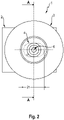
- Fig. 2:
- Eine Seitenansicht entsprechend der
Fig. 1 , - Fig. 3:
- Einen Schnitt durch die zusammengebaute Bauteilverbindung entsprechend der Schnittebene A-A in
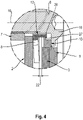
Fig. 2 , - Fig. 4:
- Einen vergrößerten Teilausschnitt entsprechend der
Fig. 3 , - Fig. 5:
- Eine Seitenansicht der vormontierten Bauteilverbindung,
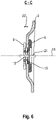
- Fig. 6:
- Einen Schnitt durch die vormontierte Bauteilverbindung entsprechend der Schnittebene C-C in
Fig. 5 . - Ein Ausführungsbeispiel, das in den
Figuren 1 bis 6 gezeigt ist, umfasst eine erfindungsgemäße Bauteilverbindung 1, die ein Verbindungsmittel 5, ein Warmbauteil 2, zwei Wärmeisolatoren 8, 9 und einem Kaltbauteil 3 umfasst. Zum formschlüssigen Verbinden der Wärmeisolatoren 8, 9 weisen diese jeweils einen Formschlussbereich 12, 13 auf. Ferner sind das Warmbauteil 2, welches hier aus Metall, vorzugsweise Stahl, gefertigt ist, und das Kaltbauteil 3, welches von temperaturempfindlichen Kunststoff gebildet ist, mit Ausnehmungen 14, 15 zum Durchdringen mit einem Schraubenbolzen 6 versehen. Die Bauteilverbindung 1 wird mittels eines Endkopfs 18 am Schraubenbolzen 6 und eine Schraubenmutter 7 montiert. - Zur Vormontage wird der Formschlussbereich 12 des ersten Wärmeisolators 8 durch die Ausnehmung 15 des Kaltbauteils 3 auf den Formschlussbereich 13 des zweiten Wärmeisolators 9 aufgeschoben. Hierbei umfasst der Formschlussbereich 12 des ersten Wärmeisolators 8 Hakenelemente 26, die dazu geeignet sind, mit einem von dem Formschlussbereich 13 des zweiten Wärmeisolators 9 bereitgestellten Anschlagkragen 27 einzugreifen. Dadurch entsteht eine formschlüssige Verbindung zwischen den Wärmeisolatoren 8, 9, zwischen denen das Kaltbauteil 3 gelagert ist. Eine unmittelbare Kraft übertragende Verbindung zwischen den Wärmeisolatoren 8, 9 und dem Kaltbauteil 3 besteht nicht. Somit bleibt das Kaltbauteil 3 innerhalb eines gewissen Bereichs relativ zu den Wärmeisolatoren 8, 9 bewegbar, wobei sich dieser Bereich zwischen einander zugewandten Flächen der Wärmeisolatoren 8, 9 erstreckt, die das Kaltbauteil 3 gewissermaßen von dessen Unterseite 11 sowie dessen Oberseite 20 einfassen.
- Zur weiteren Montage wird der Schraubbolzen 6 entlang einer Durchdringungsachse 16 durch die Ausnehmung 15, beginnend beim zweiten Wärmeisolator 9, geschoben, bis der Endkopf 18 des Schraubbolzen 6 plan von einer dem Kaltbauteil 3 abgewandten Seite am Formschlussbereich 13 des zweiten Wärmeisolators 9 anliegt. Die Wärmeisolatoren 8, 9 weisen entsprechende Ausnehmungen auf und werden entsprechend ebenfalls von dem Schraubbolzen 6 durchdrungen. Im Anschluss wird ein an der dem Kaltbauteil 3 abgewandten Seite über den ersten Wärmeisolator 8 vorstehender Schaft des Schraubbolzens 6 durch die Ausnehmung 14 des Warmbauteils 2 geschoben und abschließend mit der Schraubenmutter 7 auf der dem Kaltbauteil 2 abgewandten Seite des Warmbauteils 2 befestigt. Zur Montage weisen sowohl die Schraubmutter 7 als auch der Schraubbolzen 6 jeweils komplementäre Gewinde auf, mittels derer die Schraubmutter 7 und der Schraubbolzen 6 mittels Verschraubens verbunden werden. Andere Verbindungstechniken sind gleichermaßen möglich.
- Bei der Bauteilverbindung 1 kann es sich insbesondere um eine solche zum Einsatz an Fahrzeugen, vorzugsweise landwirtschaftlichen Arbeitsmaschinen, handeln. Das Warmbauteil 2 kann in unmittelbarem Kontakt mit einer Wärmequelle, insbesondere einem Motor der Arbeitsmaschine, stehen. Bei einer solchen Ausgestaltung weist das Warmbauteil 2 nur dann eine im Vergleich zum Kaltbauteil 3 höhere Temperatur auf, wenn der Motor der Arbeitsmaschine in Betrieb ist.
- Die Ausnehmung 15 des Kaltbauteils 3 ist hier in Form eines Langlochs mit einer Länge 21 ausgestaltet, wie aus
Figur 2 zu entnehmen ist. Entlang einer Längsachse 17 der Ausnehmung 15 weist die Verbindungseinrichtung 4 mit ein Toleranzmaß 25 auf. Durch dieses Toleranzmaß 25 hat die Verbindungseinrichtung 4 ein Spiel in Richtung der Pfeile 23, wodurch radiale Fertigungstoleranzen ausgeglichen werden können. -
Figur 3 zeigt den Schnitt entlang der Schnittebene A-A gemäßFigur 2 und dient zur Veranschaulichung der inFigur 4 dargestellten Vergrößerung der Bauteilverbindung 1. Der Formschlussbereich 12 des ersten Wärmeisolators 8, der die Ausnehmung 15 des Kaltbauteils 3 durchdringt, ist mittels zugehöriger Hakenelemente 26 formschlüssig mit einem zugehörigen Anschlagkragen 27 des Formschlussbereichs 13 des zweiten Wärmeisolators 9 verbunden. Somit ist das Kaltbauteil 3 zwischen den sich gegenüberliegend auf der Unterseite 11 und der Oberseite 20 angeordneten Wärmeisolatoren 8, 9 parallel zur Durchdringungsrichtung 16 insoweit gelagert, als es abgesehen von einem axialen Spiel sich lediglich zwischen den Wärmeisolatoren 8, 9 bewegen kann. - Abhängig von der Materialstärke des Kaltbauteils 3 ergibt sich entlang des Formschlussbereichs 12 ein Toleranzmaß 22, in dem sich das Kaltbauteil 3 entsprechend der Pfeile 24 bewegen kann. Dies ergibt sich besonders gut anhand von
Figur 6 . Insbesondere können damit axiale Fertigungstoleranzen ausgeglichen werden. In den Ausführungsbeispielen steht das Warmbauteil 2 in unmittelbarem Kontakt mit dem Verbindungsmittel 5. Allerdings kann mittels eines weiteren Wärmeisolators angeordnet zwischen dem Warmbauteil 2 und der Schraubmutter 7, welcher in den Figuren nicht abgebildet ist, in analoger Ausführung das Warmbauteil 3 von der Verbindungseinrichtung 4 thermisch entkoppelt werden. - Der Endkopf 18 des Schraubenbolzens 6 weist einen Durchmesser auf, der größer als ein Ausnehmung des Wärmeisolators 9 ist, wodurch ein vorzugsweise planes Anliegen des Endkopfs 18 an dem Formschlussbereich 13 des Wärmeisolators 9 erreicht wird.
-
- 1
- Bauteilverbindung
- 2
- Warmbauteil
- 3
- Kaltbauteil
- 4
- Verbindungseinrichtung
- 5
- Verbindungsmittel
- 6
- Schraubbolzen
- 7
- Schraubmutter
- 8
- Wärmeisolator
- 9
- Wärmeisolator
- 10
- Unterseite
- 11
- Unterseite
- 12
- Formschlussbereich
- 13
- Formschlussbereich
- 14
- Ausnehmung
- 15
- Ausnehmung
- 16
- Durchdringungsachse
- 17
- Längsachse
- 18
- Endkopf
- 19
- Oberseite
- 20
- Oberseite
- 21
- Länge
- 22
- Toleranzmaß
- 23
- Pfeil
- 24
- Pfeil
- 25
- Toleranzmaß
- 26
- Hakenelement
- 27
- Anschlagkragen
Claims (12)
- Bauteilverbindung (1), umfassend- ein Warmbauteil (2), das eine erste Temperatur aufweist,- ein Kaltbauteil (3), das eine gegenüber der Temperatur des Warmbauteils (2) verringerte Temperatur aufweist, sowie- einen Verbindungseinrichtung (4),wobei die Verbindungseinrichtung (4) ein Verbindungsmittel (5) mit einem Schraubbolzen (6) und einer korrespondierend zu dem Schraubbolzen (6) ausgebildeten Schraubmutter (7) aufweist,wobei mittels Zusammenwirkens des Schraubbolzens (6) mit der Schraubmutter (7) ein mittelbarer oder unmittelbarer formschlüssiger Eingriff des Verbindungsmittels (5) sowohl mit dem Warmbauteil (2) als auch mit dem Kaltbauteil (3) hergestellt ist, sodass das Warmbauteil (2) und das Kaltbauteil (3) in Kraft übertragender Weise miteinander verbunden sind,dadurch gekennzeichnet, dassdie Verbindungseinrichtung (4) mindestens einen Wärmeisolator (8, 9) umfasst, mittels dessen das Warmbauteil (2) und/oder das Kaltbauteil (3) thermisch von dem Verbindungsmittel (5) abgeschirmt sind,wobei der mindestens eine Wärmeisolator (8, 9) dazu eingerichtet ist, Fertigungstoleranzen auszugleichen.
- Bauteilverbindung (1) nach Anspruch 1, dadurch gekennzeichnet, dass der mindestens eine Wärmeisolator (8, 9) dem Warmbauteil (2) oder dem Kaltbauteil (3) zugeordnet ist, vorzugsweise unmittelbar mit dem Warmbauteil (2) bzw. dem Kaltbauteil (3) in Kontakt steht.
- Bauteilverbindung (1) nach einem der vorhergehenden Ansprüche, gekennzeichnet durch mindestens zwei Wärmeisolatoren (8, 9), die vorzugsweise formschlüssig miteinander verbindbar sind.
- Bauteilverbindung (1) nach dem vorhergehenden Anspruch, dadurch gekennzeichnet, dass beide Wärmeisolatoren (8, 9) dem Warmbauteil (2) oder dem Kaltbauteil (3) derart zugeordnet sind, dass ein unmittelbarer wärmeübertragender Kontakt zwischen dem Warmbauteil (2) bzw. dem Kaltbauteil (3) und dem Verbindungsmittel (5) unterbunden ist, wobei vorzugsweise mindestens ein erster Wärmeisolator (8) einer Unterseite (10, 11) und mindestens ein zweiter Wärmeisolator (9) einer Oberseite (19, 20) des Warmbauteils (2) bzw. des Kaltbauteils (3) zugeordnet sind.
- Bauteilverbindung (1) nach dem vorhergehenden Anspruch, dadurch gekennzeichnet, dass mindestens einer der Wärmeisolatoren (8, 9), vorzugsweise beide Wärmeisolatoren (8, 9), miteinander verbunden sind, einen Formschlussbereich (12, 13) aufweist bzw. aufweisen.
- Bauteilverbindung (1) nach dem vorhergehenden Anspruch, dadurch gekennzeichnet, dass zumindest ein Formschlussbereich (12, 13) der Wärmeisolatoren (8, 9) einer Ausnehmung (14, 15) des Warmbauteils (2) bzw. des Kaltbauteils (3), die das Warmbauteil (2) bzw. das Kaltbauteil (3) von dessen Unterseite (10, 11) bis zu dessen Oberseite (19, 20) durchdringt, zugeordnet ist, insbesondere sich durch die Ausnehmung (14, 15) hindurch erstreckt.
- Bauteilverbindung (1) nach dem vorhergehenden Anspruch, dadurch gekennzeichnet, dass die miteinander korrespondierenden Formschlussbereiche (12, 13) und infolgedessen die zugehörigen Wärmeisolatoren (8, 9) formschlüssig miteinander verbunden sind.
- Bauteilverbindung (1) nach dem vorhergehenden Anspruch, dadurch gekennzeichnet, dass zumindest einer der miteinander verbundenen Wärmeisolatoren (8, 9) zumindest in Richtung einer Durchdringungsachse (16) der Ausnehmung (14, 15) relativ zu dem Warmbauteil (2) bzw. dem Kaltbauteil (3) bewegbar ist, sodass eine innerhalb eines Toleranzbereichs liegende Fertigungstoleranz des Warmbauteils (2) bzw. des Kaltbauteils (3) in Richtung der Durchdringungsachse (16) ausgleichbar ist.
- Bauteilverbindung (1) nach einem der vorhergehenden Ansprüche, dadurch gekennzeichnet, dass das eine Ausnehmung (14, 15) des Warmbauteils (2) und/oder des Kaltbauteils (3) in Form eines Langlochs ausgebildet ist, sodass die Verbindungseinrichtung (4) in Richtung einer Längsachse (17) der Ausnehmung (14, 15) innerhalb eines Toleranzbereichs relativ zu dem Warmbauteil (2) bzw. dem Kaltbauteil (3) bewegbar ist.
- Bauteilverbindung (1) nach einem der vorhergehenden Ansprüche, dadurch gekennzeichnet, dass der Schraubbolzen (6) den mindestens einen Wärmeisolator (8, 9) durchdringt, wobei vorzugsweise ein Endkopf (18) des Schraubbolzens (5) einen Durchmesser einer Ausnehmung des Wärmeisolators (8, 9) übersteigt.
- Bauteilverbindung (1) nach einem der vorhergehenden Ansprüche, dadurch gekennzeichnet, dass das Warmbauteil (2) in unmittelbarem Kontakt mit dem Verbindungsmittel (5) steht.
- Verbindungseinrichtung (4) zur Kraft übertragenden Verbindung eines Warmbauteils (2), das eine erste Temperatur aufweist, mit einem Kaltbauteil (3), das eine gegenüber der Temperatur des Warmbauteils (2) verringerte Temperatur aufweist, umfassendein Verbindungsmittel (5), das einen Schraubbolzen (6) sowie eine mit dem Schraubbolzen (6) korrespondierende Schraubmutter (7) aufweist,gekennzeichnet durchmindestens einen Wärmeisolator (8, 9), mittels dessen das Warmbauteil (2) und/oder das Kaltbauteil (3) thermisch von dem Verbindungsmittel (5) abschirmbar sind,wobei der mindestens eine Wärmeisolator (8, 9) dazu eingerichtet ist, Fertigungstoleranzen auszugleichen.
Applications Claiming Priority (1)
| Application Number | Priority Date | Filing Date | Title |
|---|---|---|---|
| DE102020133939.9A DE102020133939A1 (de) | 2020-12-17 | 2020-12-17 | Bauteilverbindung sowie Verbindungseinrichtung |
Publications (2)
| Publication Number | Publication Date |
|---|---|
| EP4015843A1 true EP4015843A1 (de) | 2022-06-22 |
| EP4015843B1 EP4015843B1 (de) | 2025-07-16 |
Family
ID=78332436
Family Applications (1)
| Application Number | Title | Priority Date | Filing Date |
|---|---|---|---|
| EP21199779.6A Active EP4015843B1 (de) | 2020-12-17 | 2021-09-29 | Bauteilverbindung sowie verbindungseinrichtung |
Country Status (2)
| Country | Link |
|---|---|
| EP (1) | EP4015843B1 (de) |
| DE (1) | DE102020133939A1 (de) |
Citations (4)
| Publication number | Priority date | Publication date | Assignee | Title |
|---|---|---|---|---|
| US4050771A (en) | 1976-07-01 | 1977-09-27 | General Motors Corporation | Threaded terminal assembly for dynamoelectric machine |
| DE4029587A1 (de) * | 1989-09-20 | 1991-03-28 | Vaillant Joh Gmbh & Co | Auf einen schaft eines bolzens aufgesetzte scheibe |
| JP2014148941A (ja) * | 2013-02-01 | 2014-08-21 | Yutaka Giken Co Ltd | 排気系部品への遮熱カバー取り付け構造 |
| EP2667041B1 (de) * | 2012-05-21 | 2020-06-03 | Bayerische Motoren Werke Aktiengesellschaft | Befestigungssatz für ein Faserverbundbauteil |
-
2020
- 2020-12-17 DE DE102020133939.9A patent/DE102020133939A1/de active Pending
-
2021
- 2021-09-29 EP EP21199779.6A patent/EP4015843B1/de active Active
Patent Citations (4)
| Publication number | Priority date | Publication date | Assignee | Title |
|---|---|---|---|---|
| US4050771A (en) | 1976-07-01 | 1977-09-27 | General Motors Corporation | Threaded terminal assembly for dynamoelectric machine |
| DE4029587A1 (de) * | 1989-09-20 | 1991-03-28 | Vaillant Joh Gmbh & Co | Auf einen schaft eines bolzens aufgesetzte scheibe |
| EP2667041B1 (de) * | 2012-05-21 | 2020-06-03 | Bayerische Motoren Werke Aktiengesellschaft | Befestigungssatz für ein Faserverbundbauteil |
| JP2014148941A (ja) * | 2013-02-01 | 2014-08-21 | Yutaka Giken Co Ltd | 排気系部品への遮熱カバー取り付け構造 |
Also Published As
| Publication number | Publication date |
|---|---|
| DE102020133939A1 (de) | 2022-06-23 |
| EP4015843B1 (de) | 2025-07-16 |
Similar Documents
| Publication | Publication Date | Title |
|---|---|---|
| DE102012105402B4 (de) | Verstellvorrichtung für einen Abgasturbolader | |
| DE19537784B4 (de) | Montage einer sich selbst ausrichtenden verstellbaren Leitschaufel | |
| DE69920788T2 (de) | Befestigung von Zuzammenbauten auf einem tragenden Element | |
| DE102006004678B4 (de) | Montageeinheit für die Befestigungsöse eines Gurtschlosses | |
| DE102021105786A1 (de) | Toleranzausgleichsanordnung | |
| DE19947390A1 (de) | Kipphebelanordnung | |
| EP3581811B1 (de) | System zur befestigung einer ersten komponente an einer zweiten komponente | |
| DE69203933T2 (de) | Lagerbüchse und Befestigungsschelle für Universalgelenk. | |
| EP1419331B1 (de) | Drosselklappenanordnung | |
| EP4015843B1 (de) | Bauteilverbindung sowie verbindungseinrichtung | |
| EP3440326A1 (de) | Befestigungsvorrichtung für ein abschirmteil, insbesondere für ein hitzeschild sowie abschirmteil aufweisend zumindest eine befestigungsvorrichtung | |
| DE102021202850A1 (de) | Entkopplungselement für Hitzeschilde | |
| DE2234353A1 (de) | Federnde klammer | |
| EP1448921B1 (de) | Drosselklappenstutzen | |
| EP2156021B1 (de) | Kipphebel einer brennkraftmaschine | |
| DE102012112432B4 (de) | Halterungsvorrichtung | |
| WO2019202097A1 (de) | Vorrichtung zum verbinden und justieren von zwei bauteilen und verfahren | |
| DE102006017213A1 (de) | Metallische Flachdichtung mit zerbrechlichen Verbindungsabschnitten | |
| DE102017122640A1 (de) | Möbel und elektromotorischer Möbelantrieb mit einer Antriebseinheit und einer Führungsbahn | |
| DE102014213540A1 (de) | Hitzeschild | |
| DE19919269A1 (de) | Verriegelungshebel für eine Schaltschwinge | |
| EP1016797A2 (de) | Befestigungselement für Gewindebolzen | |
| EP4141228A1 (de) | Abgasheizer | |
| DE4131359C1 (en) | Multipart accelerator pedal for motor vehicle - has live hinge coupling pedal lever and pedal plate | |
| EP1649200B1 (de) | Teileinheit für eine zusatzsteuerventileinrichtung für einen einlasskanal einer kolbenbrennkraftmaschine |
Legal Events
| Date | Code | Title | Description |
|---|---|---|---|
| PUAI | Public reference made under article 153(3) epc to a published international application that has entered the european phase |
Free format text: ORIGINAL CODE: 0009012 |
|
| STAA | Information on the status of an ep patent application or granted ep patent |
Free format text: STATUS: THE APPLICATION HAS BEEN PUBLISHED |
|
| AK | Designated contracting states |
Kind code of ref document: A1 Designated state(s): AL AT BE BG CH CY CZ DE DK EE ES FI FR GB GR HR HU IE IS IT LI LT LU LV MC MK MT NL NO PL PT RO RS SE SI SK SM TR |
|
| STAA | Information on the status of an ep patent application or granted ep patent |
Free format text: STATUS: REQUEST FOR EXAMINATION WAS MADE |
|
| 17P | Request for examination filed |
Effective date: 20221222 |
|
| RBV | Designated contracting states (corrected) |
Designated state(s): AL AT BE BG CH CY CZ DE DK EE ES FI FR GB GR HR HU IE IS IT LI LT LU LV MC MK MT NL NO PL PT RO RS SE SI SK SM TR |
|
| P01 | Opt-out of the competence of the unified patent court (upc) registered |
Effective date: 20230516 |
|
| STAA | Information on the status of an ep patent application or granted ep patent |
Free format text: STATUS: EXAMINATION IS IN PROGRESS |
|
| 17Q | First examination report despatched |
Effective date: 20240119 |
|
| GRAP | Despatch of communication of intention to grant a patent |
Free format text: ORIGINAL CODE: EPIDOSNIGR1 |
|
| STAA | Information on the status of an ep patent application or granted ep patent |
Free format text: STATUS: GRANT OF PATENT IS INTENDED |
|
| RIC1 | Information provided on ipc code assigned before grant |
Ipc: F16B 1/00 20060101ALN20250210BHEP Ipc: F16B 43/00 20060101ALI20250210BHEP Ipc: F16B 5/02 20060101AFI20250210BHEP |
|
| INTG | Intention to grant announced |
Effective date: 20250219 |
|
| GRAS | Grant fee paid |
Free format text: ORIGINAL CODE: EPIDOSNIGR3 |
|
| GRAA | (expected) grant |
Free format text: ORIGINAL CODE: 0009210 |
|
| STAA | Information on the status of an ep patent application or granted ep patent |
Free format text: STATUS: THE PATENT HAS BEEN GRANTED |
|
| AK | Designated contracting states |
Kind code of ref document: B1 Designated state(s): AL AT BE BG CH CY CZ DE DK EE ES FI FR GB GR HR HU IE IS IT LI LT LU LV MC MK MT NL NO PL PT RO RS SE SI SK SM TR |
|
| REG | Reference to a national code |
Ref country code: GB Ref legal event code: FG4D Free format text: NOT ENGLISH |
|
| REG | Reference to a national code |
Ref country code: CH Ref legal event code: EP Ref country code: DE Ref legal event code: R096 Ref document number: 502021008004 Country of ref document: DE |
|
| REG | Reference to a national code |
Ref country code: IE Ref legal event code: FG4D Free format text: LANGUAGE OF EP DOCUMENT: GERMAN |
|
| PGFP | Annual fee paid to national office [announced via postgrant information from national office to epo] |
Ref country code: DE Payment date: 20250919 Year of fee payment: 5 |
|
| PGFP | Annual fee paid to national office [announced via postgrant information from national office to epo] |
Ref country code: AT Payment date: 20251020 Year of fee payment: 5 Ref country code: FR Payment date: 20250922 Year of fee payment: 5 |
|
| REG | Reference to a national code |
Ref country code: NL Ref legal event code: MP Effective date: 20250716 |
|
| PG25 | Lapsed in a contracting state [announced via postgrant information from national office to epo] |
Ref country code: PT Free format text: LAPSE BECAUSE OF FAILURE TO SUBMIT A TRANSLATION OF THE DESCRIPTION OR TO PAY THE FEE WITHIN THE PRESCRIBED TIME-LIMIT Effective date: 20251117 |
|
| PG25 | Lapsed in a contracting state [announced via postgrant information from national office to epo] |
Ref country code: NL Free format text: LAPSE BECAUSE OF FAILURE TO SUBMIT A TRANSLATION OF THE DESCRIPTION OR TO PAY THE FEE WITHIN THE PRESCRIBED TIME-LIMIT Effective date: 20250716 |
|
| PG25 | Lapsed in a contracting state [announced via postgrant information from national office to epo] |
Ref country code: IS Free format text: LAPSE BECAUSE OF FAILURE TO SUBMIT A TRANSLATION OF THE DESCRIPTION OR TO PAY THE FEE WITHIN THE PRESCRIBED TIME-LIMIT Effective date: 20251116 |
|
| PG25 | Lapsed in a contracting state [announced via postgrant information from national office to epo] |
Ref country code: NO Free format text: LAPSE BECAUSE OF FAILURE TO SUBMIT A TRANSLATION OF THE DESCRIPTION OR TO PAY THE FEE WITHIN THE PRESCRIBED TIME-LIMIT Effective date: 20251016 |
|
| REG | Reference to a national code |
Ref country code: LT Ref legal event code: MG9D |
|
| PG25 | Lapsed in a contracting state [announced via postgrant information from national office to epo] |
Ref country code: FI Free format text: LAPSE BECAUSE OF FAILURE TO SUBMIT A TRANSLATION OF THE DESCRIPTION OR TO PAY THE FEE WITHIN THE PRESCRIBED TIME-LIMIT Effective date: 20250716 |
|
| PG25 | Lapsed in a contracting state [announced via postgrant information from national office to epo] |
Ref country code: HR Free format text: LAPSE BECAUSE OF FAILURE TO SUBMIT A TRANSLATION OF THE DESCRIPTION OR TO PAY THE FEE WITHIN THE PRESCRIBED TIME-LIMIT Effective date: 20250716 |
|
| PG25 | Lapsed in a contracting state [announced via postgrant information from national office to epo] |
Ref country code: GR Free format text: LAPSE BECAUSE OF FAILURE TO SUBMIT A TRANSLATION OF THE DESCRIPTION OR TO PAY THE FEE WITHIN THE PRESCRIBED TIME-LIMIT Effective date: 20251017 |
|
| PG25 | Lapsed in a contracting state [announced via postgrant information from national office to epo] |
Ref country code: SE Free format text: LAPSE BECAUSE OF FAILURE TO SUBMIT A TRANSLATION OF THE DESCRIPTION OR TO PAY THE FEE WITHIN THE PRESCRIBED TIME-LIMIT Effective date: 20250716 |
|
| PG25 | Lapsed in a contracting state [announced via postgrant information from national office to epo] |
Ref country code: LV Free format text: LAPSE BECAUSE OF FAILURE TO SUBMIT A TRANSLATION OF THE DESCRIPTION OR TO PAY THE FEE WITHIN THE PRESCRIBED TIME-LIMIT Effective date: 20250716 |
|
| PG25 | Lapsed in a contracting state [announced via postgrant information from national office to epo] |
Ref country code: BG Free format text: LAPSE BECAUSE OF FAILURE TO SUBMIT A TRANSLATION OF THE DESCRIPTION OR TO PAY THE FEE WITHIN THE PRESCRIBED TIME-LIMIT Effective date: 20250716 Ref country code: PL Free format text: LAPSE BECAUSE OF FAILURE TO SUBMIT A TRANSLATION OF THE DESCRIPTION OR TO PAY THE FEE WITHIN THE PRESCRIBED TIME-LIMIT Effective date: 20250716 |
|
| PG25 | Lapsed in a contracting state [announced via postgrant information from national office to epo] |
Ref country code: RS Free format text: LAPSE BECAUSE OF FAILURE TO SUBMIT A TRANSLATION OF THE DESCRIPTION OR TO PAY THE FEE WITHIN THE PRESCRIBED TIME-LIMIT Effective date: 20251016 |
|
| PG25 | Lapsed in a contracting state [announced via postgrant information from national office to epo] |
Ref country code: ES Free format text: LAPSE BECAUSE OF FAILURE TO SUBMIT A TRANSLATION OF THE DESCRIPTION OR TO PAY THE FEE WITHIN THE PRESCRIBED TIME-LIMIT Effective date: 20250716 |
|
| PG25 | Lapsed in a contracting state [announced via postgrant information from national office to epo] |
Ref country code: RO Free format text: LAPSE BECAUSE OF FAILURE TO SUBMIT A TRANSLATION OF THE DESCRIPTION OR TO PAY THE FEE WITHIN THE PRESCRIBED TIME-LIMIT Effective date: 20250716 |
|
| PG25 | Lapsed in a contracting state [announced via postgrant information from national office to epo] |
Ref country code: SM Free format text: LAPSE BECAUSE OF FAILURE TO SUBMIT A TRANSLATION OF THE DESCRIPTION OR TO PAY THE FEE WITHIN THE PRESCRIBED TIME-LIMIT Effective date: 20250716 |
|
| PG25 | Lapsed in a contracting state [announced via postgrant information from national office to epo] |
Ref country code: DK Free format text: LAPSE BECAUSE OF FAILURE TO SUBMIT A TRANSLATION OF THE DESCRIPTION OR TO PAY THE FEE WITHIN THE PRESCRIBED TIME-LIMIT Effective date: 20250716 |
|
| PG25 | Lapsed in a contracting state [announced via postgrant information from national office to epo] |
Ref country code: IT Free format text: LAPSE BECAUSE OF FAILURE TO SUBMIT A TRANSLATION OF THE DESCRIPTION OR TO PAY THE FEE WITHIN THE PRESCRIBED TIME-LIMIT Effective date: 20250716 |
|
| REG | Reference to a national code |
Ref country code: DE Ref legal event code: R097 Ref document number: 502021008004 Country of ref document: DE |
|
| PG25 | Lapsed in a contracting state [announced via postgrant information from national office to epo] |
Ref country code: CZ Free format text: LAPSE BECAUSE OF FAILURE TO SUBMIT A TRANSLATION OF THE DESCRIPTION OR TO PAY THE FEE WITHIN THE PRESCRIBED TIME-LIMIT Effective date: 20250716 |
|
| PG25 | Lapsed in a contracting state [announced via postgrant information from national office to epo] |
Ref country code: SK Free format text: LAPSE BECAUSE OF FAILURE TO SUBMIT A TRANSLATION OF THE DESCRIPTION OR TO PAY THE FEE WITHIN THE PRESCRIBED TIME-LIMIT Effective date: 20250716 Ref country code: EE Free format text: LAPSE BECAUSE OF FAILURE TO SUBMIT A TRANSLATION OF THE DESCRIPTION OR TO PAY THE FEE WITHIN THE PRESCRIBED TIME-LIMIT Effective date: 20250716 |
|
| REG | Reference to a national code |
Ref country code: CH Ref legal event code: H13 Free format text: ST27 STATUS EVENT CODE: U-0-0-H10-H13 (AS PROVIDED BY THE NATIONAL OFFICE) Effective date: 20260504 |
|
| PG25 | Lapsed in a contracting state [announced via postgrant information from national office to epo] |
Ref country code: LU Free format text: LAPSE BECAUSE OF NON-PAYMENT OF DUE FEES Effective date: 20250929 |
|
| PLBE | No opposition filed within time limit |
Free format text: ORIGINAL CODE: 0009261 |
|
| STAA | Information on the status of an ep patent application or granted ep patent |
Free format text: STATUS: NO OPPOSITION FILED WITHIN TIME LIMIT |
|
| REG | Reference to a national code |
Ref country code: CH Ref legal event code: L10 Free format text: ST27 STATUS EVENT CODE: U-0-0-L10-L00 (AS PROVIDED BY THE NATIONAL OFFICE) Effective date: 20260528 Ref country code: BE Ref legal event code: MM Effective date: 20250930 |
|
| 26N | No opposition filed |
Effective date: 20260417 |
|
| GBPC | Gb: european patent ceased through non-payment of renewal fee |
Effective date: 20251016 |
|
| PG25 | Lapsed in a contracting state [announced via postgrant information from national office to epo] |
Ref country code: MC Free format text: LAPSE BECAUSE OF FAILURE TO SUBMIT A TRANSLATION OF THE DESCRIPTION OR TO PAY THE FEE WITHIN THE PRESCRIBED TIME-LIMIT Effective date: 20250716 Ref country code: LT Free format text: LAPSE BECAUSE OF FAILURE TO SUBMIT A TRANSLATION OF THE DESCRIPTION OR TO PAY THE FEE WITHIN THE PRESCRIBED TIME-LIMIT Effective date: 20250716 |
|
| PG25 | Lapsed in a contracting state [announced via postgrant information from national office to epo] |
Ref country code: GB Free format text: LAPSE BECAUSE OF NON-PAYMENT OF DUE FEES Effective date: 20251016 |
|
| PG25 | Lapsed in a contracting state [announced via postgrant information from national office to epo] |
Ref country code: CH Free format text: LAPSE BECAUSE OF NON-PAYMENT OF DUE FEES Effective date: 20250930 Ref country code: BE Free format text: LAPSE BECAUSE OF NON-PAYMENT OF DUE FEES Effective date: 20250930 Ref country code: IE Free format text: LAPSE BECAUSE OF NON-PAYMENT OF DUE FEES Effective date: 20250929 |