EP4015256B1 - Reifensensorbehältersystem - Google Patents
Reifensensorbehältersystem Download PDFInfo
- Publication number
- EP4015256B1 EP4015256B1 EP21211746.9A EP21211746A EP4015256B1 EP 4015256 B1 EP4015256 B1 EP 4015256B1 EP 21211746 A EP21211746 A EP 21211746A EP 4015256 B1 EP4015256 B1 EP 4015256B1
- Authority
- EP
- European Patent Office
- Prior art keywords
- tire
- sensor
- container
- container system
- pressure monitoring
- Prior art date
- Legal status (The legal status is an assumption and is not a legal conclusion. Google has not performed a legal analysis and makes no representation as to the accuracy of the status listed.)
- Active
Links
Images

Classifications
-
- B—PERFORMING OPERATIONS; TRANSPORTING
- B60—VEHICLES IN GENERAL
- B60C—VEHICLE TYRES; TYRE INFLATION; TYRE CHANGING; CONNECTING VALVES TO INFLATABLE ELASTIC BODIES IN GENERAL; DEVICES OR ARRANGEMENTS RELATED TO TYRES
- B60C11/00—Tyre tread bands; Tread patterns; Anti-skid inserts
- B60C11/24—Wear-indicating arrangements
- B60C11/243—Tread wear sensors, e.g. electronic sensors
-
- B—PERFORMING OPERATIONS; TRANSPORTING
- B60—VEHICLES IN GENERAL
- B60C—VEHICLE TYRES; TYRE INFLATION; TYRE CHANGING; CONNECTING VALVES TO INFLATABLE ELASTIC BODIES IN GENERAL; DEVICES OR ARRANGEMENTS RELATED TO TYRES
- B60C23/00—Devices for measuring, signalling, controlling, or distributing tyre pressure or temperature, specially adapted for mounting on vehicles; Arrangement of tyre inflating devices on vehicles, e.g. of pumps or of tanks; Tyre cooling arrangements
- B60C23/02—Signalling devices actuated by tyre pressure
- B60C23/04—Signalling devices actuated by tyre pressure mounted on the wheel or tyre
- B60C23/0491—Constructional details of means for attaching the control device
- B60C23/0493—Constructional details of means for attaching the control device for attachment on the tyre
-
- G—PHYSICS
- G01—MEASURING; TESTING
- G01L—MEASURING FORCE, STRESS, TORQUE, WORK, MECHANICAL POWER, MECHANICAL EFFICIENCY, OR FLUID PRESSURE
- G01L17/00—Devices or apparatus for measuring tyre pressure or the pressure in other inflated bodies
-
- G—PHYSICS
- G01—MEASURING; TESTING
- G01L—MEASURING FORCE, STRESS, TORQUE, WORK, MECHANICAL POWER, MECHANICAL EFFICIENCY, OR FLUID PRESSURE
- G01L19/00—Details of, or accessories for, apparatus for measuring steady or quasi-steady pressure of a fluent medium insofar as such details or accessories are not special to particular types of pressure gauges
- G01L19/0092—Pressure sensor associated with other sensors, e.g. for measuring acceleration or temperature
Definitions
- the invention relates to vehicle tires. More particularly, the invention relates to vehicle tires with sensors that determine various conditions within the tires. Specifically, the invention is directed to a sensor container system for a tire, which includes a sensor and container structure that maintains a consistent sensor orientation with respect to an innerliner of the tire.
- the tire In the manufacture of a pneumatic tire, the tire is typically built on the drum of a tire-building machine, which is known in the art as a tire building drum. Numerous tire components are wrapped about and/or applied to the drum in sequence, forming a cylindrical-shaped tire carcass. The tire carcass is then expanded into a toroidal shape for receipt of the remaining components of the tire, such as a belt package and a rubber tread. The completed toroidally-shaped unvulcanized tire carcass, which is known in the art at that stage as a green tire, is then inserted into a mold or press for forming of the tread pattern and curing or vulcanization.
- Some tires include a sensor for a tire pressure monitoring system (TPMS), which enables the pressure inside the tire to be monitored.
- TPMS tire pressure monitoring system
- a TPMS sensor typically includes an antenna for wirelessly transmitted measured data to a receiver unit for processing and/or storage.
- TPMS sensors have been directly mounted to an innerliner of the tire through direct attachment using an adhesive.
- direct attachment made replacement of the TPMS sensor difficult.
- some TPMS sensors have been mounted to the innerliner using a flexible housing or container, which enables replacement of the TPMS sensor, while withstanding the dynamic environment of the tire.
- WO 2018/047781 A1 describes a tire sensor container system in accordance with the preamble of claim 1.
- KR 102 124 829 B1 discloses a tire tread wear determination system that is incorporated into a tire tread.
- the invention relates to a system in accordance with claim 1.
- a tire sensor container system includes a carcass toroidally extending from a first bead area to a second bead area, and an innerliner being formed on an inner surface of the carcass.
- the tire sensor container system includes a tire pressure monitoring system sensor that includes a rigid housing formed with an oval shape.
- a flexible container is mounted to the innerliner.
- the container includes a base and a wall extending radially outwardly from the base, and the wall terminates in a lip.
- the container wall is formed with an oval shape that cooperates with the shape of the tire pressure monitoring sensor housing.
- a cavity is defined by the base, the wall, and the lip, and the cavity receives and secures the tire pressure monitoring system sensor.
- Axial and “axially” mean lines or directions that are parallel to the axis of rotation of the tire.
- Carcass means the tire structure apart from the belt structure, tread, undertread, and sidewall rubber over the plies, but including the beads.
- Ring and radially mean lines or directions that are perpendicular to the axis of rotation of the tire.
- TPMS means a tire pressure monitoring system, which is an electronic system that measures the internal pressure of a tire and is capable of communicating the pressure to a processor that is mounted on the vehicle and/or is in electronic communication with electronic systems of the vehicle.
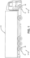
- FIG. 1 An exemplary embodiment of the tire sensor container system 10 of the present invention is presented in Figures 1 through 8 .
- one or more tires 12 supports a vehicle 14. While the vehicle 14 is depicted as a commercial truck, the invention is not to be so restricted. The principles of the invention find application in other vehicle categories, such as passenger vehicles, off-the-road vehicles and the like, in which vehicles may be supported by more or fewer tires than shown in Figure 1 .
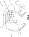
- the tire 12 includes a pair of bead areas 16, each one of which is formed with a bead core 18 that is embedded in the respective bead areas.
- Each one of a pair of sidewalls 20 extends radially outwardly from a respective bead area 16 to a ground-contacting tread 22.
- the tire 12 is reinforced by a carcass 24 that toroidally extends from one bead area 16 to the other bead area, as known to those skilled in the art.
- An innerliner 26 is formed on the inner or inside surface of the carcass 24.
- the tire 12 is mounted on the flange of a wheel or rim 36 ( Figure 1 ) as known in the art, forming an internal cavity 30.
- a sensor unit 28 is mounted to the tire 12.
- the sensor unit 28 is suitable to detect certain real-time parameters of the tire 12, and preferably includes a pressure sensor to sense the inflation pressure within a cavity 30 of the tire, and a temperature sensor to sense the temperature of the tire and/or the temperature in the cavity.
- the sensor unit 28 preferably is a commercially available tire pressure monitoring system (TPMS) module or sensing unit and shall be referred to herein for the purpose of convenience as a TPMS sensor.
- TPMS tire pressure monitoring system
- the TPMS sensor 28 preferably also includes a processor and memory to store tire identification (ID) information for each specific tire 12.
- the tire ID may include manufacturing information for the tire 12, including: the tire model; size information, such as rim size, width, and outer diameter; manufacturing location; manufacturing date; a treadcap code that includes or correlates to a compound identification; and a mold code that includes or correlates to a tread structure identification.
- the tire ID may also include a service history or other information to identify specific features and parameters of each tire 12.
- the TPMS sensor 28 preferably further includes an antenna for wirelessly transmitting 32 measured parameters and tire ID data to a receiver or remote processor for analysis, such as a processor integrated into a vehicle electronic control unit and/or CAN bus.
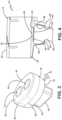
- the TPMS sensor 28 includes a relatively rigid housing 50 formed with a base 52.
- a pair of electrical contacts 54 are preferably mounted on the base 52 and extend through the housing 50.
- the electrical contacts 54 enable the TPMS sensor 28 to electrically connect with other sensors 34 ( Figure 4 ), such as tread wear sensors, temperature sensors, accelerometers, load sensors, and the like.
- the housing 50 of the TPMS sensor 28 is preferably formed with an oval shape to prevent rotation of the sensor relative to the tire innerliner 26, as will be described in greater detail below.
- the housing 50 includes a pair of elongated sides 40 extending parallel to one another, and a pair of ends 42 that extend parallel to one another, and which are shorter than the sides 40.
- the housing 50 also includes a top 44 opposite the base 52, and a protrusion 46 extending radially from the top away from the housing.
- the protrusion 46 preferably is formed with a rectangular cross section, which enables the TPMS sensor 28 to be easily inserted into a container 38 ( Figure 2 ), removed from the container, and manually rotated in the container to a desired orientation with respect to the innerliner 26.
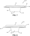
- the TPMS sensor 28 is mounted to the tire 12 using a container 38, which enables the TPMS sensor to easily be removed and replaced when needed.
- the container 38 is flexible and preferably is formed of an elastomer or polymer.
- the container 38 includes a base 56 with a circular shape or an oval shape, and a wall 58 extending radially outwardly from the base.
- the wall 58 terminates in a lip 60, which defines an opening 62.
- the wall 58 is formed with an oval shape and includes a pair of elongated sides 64 extending parallel to one another, and a pair of ends 66 extending parallel to one another and are shorter than the sides 64. In this manner, the shape of the container wall 58 corresponds to and cooperates with the shape of the TPMS sensor housing 50.
- the base 56, wall 58 and lip 60 cooperate to define a first cavity 68, which receives and secures the TPMS sensor 28.
- the TPMS sensor 28 is inserted into the first cavity 68 of the container 38 through the opening 62. Because the container 38 is formed of a flexible material, the wall 58 and lip 60 flex to allow insertion of the TPMS sensor 28 through the opening 62, and then secure the TPMS sensor in the first cavity 68.
- the oval shape of the container wall 58 cooperates with the oval shape of the TPMS sensor housing 50.
- the oval-shaped sensor housing 50 securely seats in the first cavity 68, which is defined by the oval-shaped sensor wall 58, the orientation of the TPMS sensor 28 is secured and maintained, thereby minimizing rotation of the TPMS sensor relative to the innerliner 26 during vehicle operation.
- the wall 58 and base 56 of the container 38 preferably also form a second cavity 70, which is adjacent the first cavity 68.
- the second cavity 68 retains another sensor 34, such as such as a tread wear sensor, temperature sensor, accelerometer, load sensor, and the like.
- the flexible elastomer or polymer material of the container 38 ensures that the container retains both the TPMS sensor 28 and the additional sensor 34 and maintains electrical contact between the TPMS sensor and the additional sensor.
- the protrusion 46 on the TPMS sensor 28 enables the TPMS sensor to be manually adjusted or rotated in the first cavity 68 to ensure alignment of the electrical contacts 54 with the additional sensor 34.
- the base 56 of the container 38 is formed with a bottom surface 72, which contacts and is secured to the innerliner 26.
- the bottom surface 72 of the base 56 is attached to the innerliner 26 by an adhesive.
- the bottom surface 72 of the base 56 is formed with a double curvature 74 to improve contact with tire innerliner 26 and to maintain a compressive holding force on the TPMS sensor 28.
- the container 38 and the TPMS sensor 28 of the tire sensor container system 10 of the present invention are formed with complementary oval shapes, which cooperate to secure the position of the TPMS sensor, while enabling easy replacement of the TPMS sensor.
- the tire sensor container system 10 reduces rotation of the TPMS sensor 28 with respect to the tire innerliner 26, thereby maintaining a consistent orientation of the sensor to improve the functionality and longevity of the sensor.
- the tire sensor container system 10 maintains electrical contact between the TPMS sensor 28 and any additional sensors 34.
Landscapes
- Engineering & Computer Science (AREA)
- Mechanical Engineering (AREA)
- Physics & Mathematics (AREA)
- General Physics & Mathematics (AREA)
- Chemical & Material Sciences (AREA)
- Analytical Chemistry (AREA)
- Measuring Fluid Pressure (AREA)
- Tires In General (AREA)
Claims (15)
- Behältersystem für einen Reifensensor, das einen Reifen (12) umfasst, wobei der Reifen (12) eine Karkasse (24), die sich toroidförmig von einem ersten Wulstbereich (18) zu einem zweiten Wulstbereich (18) erstreckt, und eine Innenschicht (26), die auf einer inneren Fläche der Karkasse (24) ausgebildet ist, umfasst, wobei das Behältersystem für einen Reifensensor (10) ferner umfasst:eine Sensoreinheit (28) des Reifendrucküberwachungssystems, wobei die Sensoreinheit (28) des Reifendrucküberwachungssystems ein relativ starres Gehäuse (50) aufweist;einen flexiblen Behälter (38), der an der Innenschicht (26) angebracht ist, wobei der Behälter (38) eine Basis (56) und eine Wand (58) aufweist, die sich von der Basis (56) radial nach außen erstreckt, wobei die Wand (58) in einer Lippe (60) endet;einen Hohlraum (68), der durch die Basis (56), die Wand (58) und die Lippe (60) definiert ist, wobei der Hohlraum so konfiguriert ist, dass er die Sensoreinheit (28) des Reifendrucküberwachungssystems aufnimmt und befestigt; dadurch gekennzeichnet, dassdas Gehäuse (50) mit einer ovalen Form ausgebildet ist und dass die Wand (58) mit einer ovalen Form ausgebildet ist, die mit der Form des Gehäuses (50) des Reifendrucküberwachungssensors zusammenwirkt.
- Reifendrucksensor-Behältersystem nach Anspruch 1, wobei die Sensoreinheit (28) des Reifendrucküberwachungssystems eine obere Seite (44) des Gehäuses (50) gegenüber einer Basis (52) und einen Vorsprung (46) aufweist, der sich radial von der Oberseite (44) und weg von dem Gehäuse (50) erstreckt.
- Behältersystem für einen Reifensensor nach Anspruch 2, wobei der Vorsprung (46) mit einem rechteckigen Querschnitt ausgebildet ist.
- Behältersystem für einen Reifensensor nach mindestens einem der vorhergehenden Ansprüche, wobei der Behälter (38) aus mindestens einem von einem Elastomer und einem Polymer gebildet ist.
- Behältersystem für einen Reifensensor nach mindestens einem der vorhergehenden Ansprüche, wobei die Basis (56) des Behälters eine kreisförmige oder ovale Form aufweist.
- Behältersystem für einen Reifensensor nach mindestens einem der vorhergehenden Ansprüche, wobei die Lippe (60) eine Öffnung (62) definiert, und wobei die Sensoreinheit (38) des Reifendrucküberwachungssystems durch die Öffnung (62) in den Hohlraum (68) des Behälters (38) eingeführt wird.
- Behältersystem für einen Reifensensor nach mindestens einem der vorhergehenden Ansprüche, wobei das Gehäuse (50) der Sensoreinheit des Reifendrucküberwachungssystems eine Basis (52) umfasst, und wobei ein Paar elektrischer Kontakte (54) an der Basis (52) angebracht ist.
- Behältersystem für einen Reifensensor nach mindestens einem der vorhergehenden Ansprüche, wobei der Hohlraum ein erster Hohlraum (68) ist, und wobei die Wand (58) und die Basis (52) des Behälters (38) einen zweiten Hohlraum (70) bilden, der an den ersten Hohlraum (68) angrenzt.
- Behältersystem für einen Reifensensor nach Anspruch 8, das ferner einen zusätzlichen Sensor (34) umfasst, der in dem zweiten Hohlraum (70) angeordnet ist.
- Behältersystem für einen Reifensensor nach Anspruch 9, wobei der zusätzliche Sensor (34) mindestens einen von einem Laufflächenverschleißsensor, einem Temperatursensor, einem Beschleunigungsmesser und einem Belastungssensor umfasst.
- Behältersystem für einen Reifensensor nach mindestens einem der vorhergehenden Ansprüche 9 oder 10, wobei der Behälter (38) den elektrischen Kontakt zwischen der Sensoreinheit (28) des Reifendrucküberwachungssystems und dem zusätzlichen Sensor (34) aufrechterhält.
- Behältersystem für einen Reifensensor nach mindestens einem der vorhergehenden Ansprüche 9 bis 11, wobei ein Vorsprung (46) an dem Gehäuse (50) der Sensoreinheit des Reifendrucküberwachungssystems (28) ausgebildet ist, wobei der Vorsprung (46) eine manuelle Drehung der Sensoreinheit des Reifendrucküberwachungssystems (28) in dem Behälter (38) ermöglicht, um eine Ausrichtung der elektrischen Kontakte (54) mit dem zusätzlichen Sensor (34) sicherzustellen.
- Behältersystem für einen Reifensensor nach mindestens einem der vorhergehenden Ansprüche, wobei die Basis (56) des Behälters (38) mit einer Bodenfläche (72) ausgebildet ist, wobei die Bodenfläche (72) die Innenschicht (26) berührt und an dieser befestigt ist.
- Behältersystem für einen Reifensensor nach Anspruch 13, wobei die Bodenfläche (72) durch einen Klebstoff an der Innenschicht (26) befestigt ist.
- Behältersystem für einen Reifensensor nach Anspruch 13 oder 14, wobei die Bodenfläche (72) mit einer Doppelkrümmung (74) ausgebildet ist.
Applications Claiming Priority (2)
| Application Number | Priority Date | Filing Date | Title |
|---|---|---|---|
| US202063125455P | 2020-12-15 | 2020-12-15 | |
| US17/502,078 US11628695B2 (en) | 2020-12-15 | 2021-10-15 | Tire sensor container system for improved sensor functionality and longevity |
Publications (2)
| Publication Number | Publication Date |
|---|---|
| EP4015256A1 EP4015256A1 (de) | 2022-06-22 |
| EP4015256B1 true EP4015256B1 (de) | 2024-09-04 |
Family
ID=78820624
Family Applications (1)
| Application Number | Title | Priority Date | Filing Date |
|---|---|---|---|
| EP21211746.9A Active EP4015256B1 (de) | 2020-12-15 | 2021-12-01 | Reifensensorbehältersystem |
Country Status (2)
| Country | Link |
|---|---|
| US (1) | US11628695B2 (de) |
| EP (1) | EP4015256B1 (de) |
Families Citing this family (1)
| Publication number | Priority date | Publication date | Assignee | Title |
|---|---|---|---|---|
| CN118817148A (zh) * | 2024-07-04 | 2024-10-22 | 上海源悦汽车电子股份有限公司 | 一种高效tpms传感器模块测试系统 |
Citations (1)
| Publication number | Priority date | Publication date | Assignee | Title |
|---|---|---|---|---|
| US20140355648A1 (en) * | 2011-12-29 | 2014-12-04 | Pirelli Tyre S.P.A | Monitoring device for tyres for vehicle wheels, tyre for vehicle wheels provided with said monitoring device, and method for installing an electronic unit in said tyre |
Family Cites Families (17)
| Publication number | Priority date | Publication date | Assignee | Title |
|---|---|---|---|---|
| US5971046A (en) | 1997-09-17 | 1999-10-26 | Bridgestone/Firestone, Inc. | Method and apparatus for bonding an active tag to a patch and a tire |
| DE19745734B4 (de) | 1997-10-16 | 2007-07-05 | Bayerische Motoren Werke Ag | Abriebsensor zur Erfassung der Profiltiefe eines Reifens von Kraftfahrzeugen |
| US6546982B1 (en) * | 1998-08-03 | 2003-04-15 | The Goodyear Tire & Rubber Company | Mounting transponders in pneumatic tires |
| US6885291B1 (en) * | 1999-11-15 | 2005-04-26 | The Goodyear Tire & Rubber Company | Mouting transponders and antennas in pneumatic tires |
| US6889153B2 (en) | 2001-08-09 | 2005-05-03 | Thomas Dietiker | System and method for a self-calibrating non-invasive sensor |
| DE20216290U1 (de) | 2002-10-23 | 2003-01-23 | Continental Aktiengesellschaft, 30165 Hannover | Fahrzeugreifen |
| JP4316313B2 (ja) | 2003-07-09 | 2009-08-19 | 横浜ゴム株式会社 | タイヤ摩耗検知方法と装置、及び空気入りタイヤ |
| US7280036B2 (en) * | 2005-05-04 | 2007-10-09 | Eric Adel Kafrawy | Detection and warning system |
| DE102007001279B4 (de) | 2007-01-08 | 2021-02-11 | Continental Reifen Deutschland Gmbh | Fahrzeugluftreifen mit einem Elektronikmodul |
| DE102010000003A1 (de) | 2010-01-05 | 2011-07-07 | Continental Reifen Deutschland GmbH, 30165 | Reifenmodul für Fahrzeugreifen |
| US9016118B2 (en) * | 2010-12-22 | 2015-04-28 | Caterpillar Inc. | Mounting structure |
| US8596117B2 (en) | 2011-10-03 | 2013-12-03 | Bridgestone Americas Tire Operations, Llc | Attachment patch for mounting various devices |
| US9283817B2 (en) * | 2011-11-22 | 2016-03-15 | The Goodyear Tire & Rubber Company | Stiffness enhanced tread |
| US9649889B2 (en) * | 2012-12-13 | 2017-05-16 | The Goodyear Tire & Rubber Company | Autonomous, plug-in wear or abrasion sensing system |
| US9352615B2 (en) * | 2013-10-22 | 2016-05-31 | The Goodyear Tire & Rubber Company | Pneumatic tire with multi-tread cap |
| JP6617666B2 (ja) * | 2016-09-07 | 2019-12-11 | 株式会社デンソー | タイヤマウントセンサ |
| KR102124829B1 (ko) | 2020-02-10 | 2020-06-22 | 유성원 | 타이어 마모 감지 장치 |
-
2021
- 2021-10-15 US US17/502,078 patent/US11628695B2/en active Active
- 2021-12-01 EP EP21211746.9A patent/EP4015256B1/de active Active
Patent Citations (1)
| Publication number | Priority date | Publication date | Assignee | Title |
|---|---|---|---|---|
| US20140355648A1 (en) * | 2011-12-29 | 2014-12-04 | Pirelli Tyre S.P.A | Monitoring device for tyres for vehicle wheels, tyre for vehicle wheels provided with said monitoring device, and method for installing an electronic unit in said tyre |
Also Published As
| Publication number | Publication date |
|---|---|
| US20220185043A1 (en) | 2022-06-16 |
| EP4015256A1 (de) | 2022-06-22 |
| US11628695B2 (en) | 2023-04-18 |
Similar Documents
| Publication | Publication Date | Title |
|---|---|---|
| US10935466B2 (en) | Integrated tire sensor and reader system | |
| US20060090558A1 (en) | Tire wear sensor | |
| US11260705B2 (en) | Flexible tire sensor unit | |
| US11964515B2 (en) | Integrated tread wear sensor and TPMS container for a tire | |
| US20240343073A1 (en) | Tire with polymer plug for tread wear sensing | |
| US11738604B2 (en) | Sensor retaining system for vehicle tire | |
| JP7666917B2 (ja) | 埋め込まれて封入されたタイヤセンサユニット | |
| US20250367985A1 (en) | Antenna connection for integrated rfid tag and tpms sensor | |
| EP4015256B1 (de) | Reifensensorbehältersystem | |
| EP4197823A1 (de) | Reifen mit zellelement und sensor | |
| US20200189533A1 (en) | Control system for an air maintenance tire system | |
| US11639077B2 (en) | Tire with tread wear sensor plug | |
| JP2003501733A (ja) | 自動車タイヤの空気圧を検知するためのシステム | |
| CN116323258A (zh) | 车辆速度控制系统 | |
| JP4959575B2 (ja) | 車両の地面接触構成要素、タイヤおよび測定装置の使用 | |
| CN118302308B (zh) | 轮胎 | |
| US11938762B2 (en) | Tire sensor attachment structure | |
| EP4197820A1 (de) | Integrierter laufflächenverschleisssensor und tpms-behälter für einen reifen | |
| US20240418607A1 (en) | Detection of uneven and irregular treadwear | |
| CN116262402A (zh) | 具有蜂窝状构件和传感器的轮胎 | |
| US20250153517A1 (en) | Systems and methods for including sensors on wheels | |
| CN119159931A (zh) | 不均匀和不规则胎面磨损的检测 |
Legal Events
| Date | Code | Title | Description |
|---|---|---|---|
| PUAI | Public reference made under article 153(3) epc to a published international application that has entered the european phase |
Free format text: ORIGINAL CODE: 0009012 |
|
| STAA | Information on the status of an ep patent application or granted ep patent |
Free format text: STATUS: THE APPLICATION HAS BEEN PUBLISHED |
|
| AK | Designated contracting states |
Kind code of ref document: A1 Designated state(s): AL AT BE BG CH CY CZ DE DK EE ES FI FR GB GR HR HU IE IS IT LI LT LU LV MC MK MT NL NO PL PT RO RS SE SI SK SM TR |
|
| STAA | Information on the status of an ep patent application or granted ep patent |
Free format text: STATUS: REQUEST FOR EXAMINATION WAS MADE |
|
| 17P | Request for examination filed |
Effective date: 20221222 |
|
| RBV | Designated contracting states (corrected) |
Designated state(s): AL AT BE BG CH CY CZ DE DK EE ES FI FR GB GR HR HU IE IS IT LI LT LU LV MC MK MT NL NO PL PT RO RS SE SI SK SM TR |
|
| STAA | Information on the status of an ep patent application or granted ep patent |
Free format text: STATUS: EXAMINATION IS IN PROGRESS |
|
| 17Q | First examination report despatched |
Effective date: 20230811 |
|
| GRAP | Despatch of communication of intention to grant a patent |
Free format text: ORIGINAL CODE: EPIDOSNIGR1 |
|
| STAA | Information on the status of an ep patent application or granted ep patent |
Free format text: STATUS: GRANT OF PATENT IS INTENDED |
|
| INTG | Intention to grant announced |
Effective date: 20240327 |
|
| GRAS | Grant fee paid |
Free format text: ORIGINAL CODE: EPIDOSNIGR3 |
|
| GRAA | (expected) grant |
Free format text: ORIGINAL CODE: 0009210 |
|
| STAA | Information on the status of an ep patent application or granted ep patent |
Free format text: STATUS: THE PATENT HAS BEEN GRANTED |
|
| AK | Designated contracting states |
Kind code of ref document: B1 Designated state(s): AL AT BE BG CH CY CZ DE DK EE ES FI FR GB GR HR HU IE IS IT LI LT LU LV MC MK MT NL NO PL PT RO RS SE SI SK SM TR |
|
| REG | Reference to a national code |
Ref country code: GB Ref legal event code: FG4D |
|
| REG | Reference to a national code |
Ref country code: CH Ref legal event code: EP |
|
| REG | Reference to a national code |
Ref country code: DE Ref legal event code: R096 Ref document number: 602021018248 Country of ref document: DE |
|
| REG | Reference to a national code |
Ref country code: IE Ref legal event code: FG4D |
|
| REG | Reference to a national code |
Ref country code: LT Ref legal event code: MG9D |
|
| REG | Reference to a national code |
Ref country code: NL Ref legal event code: MP Effective date: 20240904 |
|
| PG25 | Lapsed in a contracting state [announced via postgrant information from national office to epo] |
Ref country code: NO Free format text: LAPSE BECAUSE OF FAILURE TO SUBMIT A TRANSLATION OF THE DESCRIPTION OR TO PAY THE FEE WITHIN THE PRESCRIBED TIME-LIMIT Effective date: 20241204 |
|
| PG25 | Lapsed in a contracting state [announced via postgrant information from national office to epo] |
Ref country code: GR Free format text: LAPSE BECAUSE OF FAILURE TO SUBMIT A TRANSLATION OF THE DESCRIPTION OR TO PAY THE FEE WITHIN THE PRESCRIBED TIME-LIMIT Effective date: 20241205 Ref country code: PL Free format text: LAPSE BECAUSE OF FAILURE TO SUBMIT A TRANSLATION OF THE DESCRIPTION OR TO PAY THE FEE WITHIN THE PRESCRIBED TIME-LIMIT Effective date: 20240904 Ref country code: FI Free format text: LAPSE BECAUSE OF FAILURE TO SUBMIT A TRANSLATION OF THE DESCRIPTION OR TO PAY THE FEE WITHIN THE PRESCRIBED TIME-LIMIT Effective date: 20240904 |
|
| PG25 | Lapsed in a contracting state [announced via postgrant information from national office to epo] |
Ref country code: BG Free format text: LAPSE BECAUSE OF FAILURE TO SUBMIT A TRANSLATION OF THE DESCRIPTION OR TO PAY THE FEE WITHIN THE PRESCRIBED TIME-LIMIT Effective date: 20240904 |
|
| PG25 | Lapsed in a contracting state [announced via postgrant information from national office to epo] |
Ref country code: LV Free format text: LAPSE BECAUSE OF FAILURE TO SUBMIT A TRANSLATION OF THE DESCRIPTION OR TO PAY THE FEE WITHIN THE PRESCRIBED TIME-LIMIT Effective date: 20240904 |
|
| PG25 | Lapsed in a contracting state [announced via postgrant information from national office to epo] |
Ref country code: HR Free format text: LAPSE BECAUSE OF FAILURE TO SUBMIT A TRANSLATION OF THE DESCRIPTION OR TO PAY THE FEE WITHIN THE PRESCRIBED TIME-LIMIT Effective date: 20240904 |
|
| PG25 | Lapsed in a contracting state [announced via postgrant information from national office to epo] |
Ref country code: ES Free format text: LAPSE BECAUSE OF FAILURE TO SUBMIT A TRANSLATION OF THE DESCRIPTION OR TO PAY THE FEE WITHIN THE PRESCRIBED TIME-LIMIT Effective date: 20240904 Ref country code: RS Free format text: LAPSE BECAUSE OF FAILURE TO SUBMIT A TRANSLATION OF THE DESCRIPTION OR TO PAY THE FEE WITHIN THE PRESCRIBED TIME-LIMIT Effective date: 20241204 |
|
| PG25 | Lapsed in a contracting state [announced via postgrant information from national office to epo] |
Ref country code: RS Free format text: LAPSE BECAUSE OF FAILURE TO SUBMIT A TRANSLATION OF THE DESCRIPTION OR TO PAY THE FEE WITHIN THE PRESCRIBED TIME-LIMIT Effective date: 20241204 Ref country code: PL Free format text: LAPSE BECAUSE OF FAILURE TO SUBMIT A TRANSLATION OF THE DESCRIPTION OR TO PAY THE FEE WITHIN THE PRESCRIBED TIME-LIMIT Effective date: 20240904 Ref country code: NO Free format text: LAPSE BECAUSE OF FAILURE TO SUBMIT A TRANSLATION OF THE DESCRIPTION OR TO PAY THE FEE WITHIN THE PRESCRIBED TIME-LIMIT Effective date: 20241204 Ref country code: LV Free format text: LAPSE BECAUSE OF FAILURE TO SUBMIT A TRANSLATION OF THE DESCRIPTION OR TO PAY THE FEE WITHIN THE PRESCRIBED TIME-LIMIT Effective date: 20240904 Ref country code: HR Free format text: LAPSE BECAUSE OF FAILURE TO SUBMIT A TRANSLATION OF THE DESCRIPTION OR TO PAY THE FEE WITHIN THE PRESCRIBED TIME-LIMIT Effective date: 20240904 Ref country code: GR Free format text: LAPSE BECAUSE OF FAILURE TO SUBMIT A TRANSLATION OF THE DESCRIPTION OR TO PAY THE FEE WITHIN THE PRESCRIBED TIME-LIMIT Effective date: 20241205 Ref country code: FI Free format text: LAPSE BECAUSE OF FAILURE TO SUBMIT A TRANSLATION OF THE DESCRIPTION OR TO PAY THE FEE WITHIN THE PRESCRIBED TIME-LIMIT Effective date: 20240904 Ref country code: ES Free format text: LAPSE BECAUSE OF FAILURE TO SUBMIT A TRANSLATION OF THE DESCRIPTION OR TO PAY THE FEE WITHIN THE PRESCRIBED TIME-LIMIT Effective date: 20240904 Ref country code: BG Free format text: LAPSE BECAUSE OF FAILURE TO SUBMIT A TRANSLATION OF THE DESCRIPTION OR TO PAY THE FEE WITHIN THE PRESCRIBED TIME-LIMIT Effective date: 20240904 |
|
| REG | Reference to a national code |
Ref country code: AT Ref legal event code: MK05 Ref document number: 1720011 Country of ref document: AT Kind code of ref document: T Effective date: 20240904 |
|
| PG25 | Lapsed in a contracting state [announced via postgrant information from national office to epo] |
Ref country code: NL Free format text: LAPSE BECAUSE OF FAILURE TO SUBMIT A TRANSLATION OF THE DESCRIPTION OR TO PAY THE FEE WITHIN THE PRESCRIBED TIME-LIMIT Effective date: 20240904 |
|
| PG25 | Lapsed in a contracting state [announced via postgrant information from national office to epo] |
Ref country code: IS Free format text: LAPSE BECAUSE OF FAILURE TO SUBMIT A TRANSLATION OF THE DESCRIPTION OR TO PAY THE FEE WITHIN THE PRESCRIBED TIME-LIMIT Effective date: 20250104 Ref country code: PT Free format text: LAPSE BECAUSE OF FAILURE TO SUBMIT A TRANSLATION OF THE DESCRIPTION OR TO PAY THE FEE WITHIN THE PRESCRIBED TIME-LIMIT Effective date: 20250106 |
|
| PG25 | Lapsed in a contracting state [announced via postgrant information from national office to epo] |
Ref country code: RO Free format text: LAPSE BECAUSE OF FAILURE TO SUBMIT A TRANSLATION OF THE DESCRIPTION OR TO PAY THE FEE WITHIN THE PRESCRIBED TIME-LIMIT Effective date: 20240904 Ref country code: SM Free format text: LAPSE BECAUSE OF FAILURE TO SUBMIT A TRANSLATION OF THE DESCRIPTION OR TO PAY THE FEE WITHIN THE PRESCRIBED TIME-LIMIT Effective date: 20240904 |
|
| PG25 | Lapsed in a contracting state [announced via postgrant information from national office to epo] |
Ref country code: EE Free format text: LAPSE BECAUSE OF FAILURE TO SUBMIT A TRANSLATION OF THE DESCRIPTION OR TO PAY THE FEE WITHIN THE PRESCRIBED TIME-LIMIT Effective date: 20240904 Ref country code: AT Free format text: LAPSE BECAUSE OF FAILURE TO SUBMIT A TRANSLATION OF THE DESCRIPTION OR TO PAY THE FEE WITHIN THE PRESCRIBED TIME-LIMIT Effective date: 20240904 |
|
| PG25 | Lapsed in a contracting state [announced via postgrant information from national office to epo] |
Ref country code: CZ Free format text: LAPSE BECAUSE OF FAILURE TO SUBMIT A TRANSLATION OF THE DESCRIPTION OR TO PAY THE FEE WITHIN THE PRESCRIBED TIME-LIMIT Effective date: 20240904 |
|
| PG25 | Lapsed in a contracting state [announced via postgrant information from national office to epo] |
Ref country code: SK Free format text: LAPSE BECAUSE OF FAILURE TO SUBMIT A TRANSLATION OF THE DESCRIPTION OR TO PAY THE FEE WITHIN THE PRESCRIBED TIME-LIMIT Effective date: 20240904 |
|
| REG | Reference to a national code |
Ref country code: DE Ref legal event code: R026 Ref document number: 602021018248 Country of ref document: DE |
|
| PLBI | Opposition filed |
Free format text: ORIGINAL CODE: 0009260 |
|
| PG25 | Lapsed in a contracting state [announced via postgrant information from national office to epo] |
Ref country code: MC Free format text: LAPSE BECAUSE OF FAILURE TO SUBMIT A TRANSLATION OF THE DESCRIPTION OR TO PAY THE FEE WITHIN THE PRESCRIBED TIME-LIMIT Effective date: 20240904 |
|
| 26 | Opposition filed |
Opponent name: BRIDGESTONE EUROPE NV/SA Effective date: 20250604 |
|
| PG25 | Lapsed in a contracting state [announced via postgrant information from national office to epo] |
Ref country code: DK Free format text: LAPSE BECAUSE OF FAILURE TO SUBMIT A TRANSLATION OF THE DESCRIPTION OR TO PAY THE FEE WITHIN THE PRESCRIBED TIME-LIMIT Effective date: 20240904 |
|
| PLAX | Notice of opposition and request to file observation + time limit sent |
Free format text: ORIGINAL CODE: EPIDOSNOBS2 |
|
| REG | Reference to a national code |
Ref country code: CH Ref legal event code: PL |
|
| PG25 | Lapsed in a contracting state [announced via postgrant information from national office to epo] |
Ref country code: LU Free format text: LAPSE BECAUSE OF NON-PAYMENT OF DUE FEES Effective date: 20241201 |
|
| PG25 | Lapsed in a contracting state [announced via postgrant information from national office to epo] |
Ref country code: SE Free format text: LAPSE BECAUSE OF FAILURE TO SUBMIT A TRANSLATION OF THE DESCRIPTION OR TO PAY THE FEE WITHIN THE PRESCRIBED TIME-LIMIT Effective date: 20240904 |
|
| REG | Reference to a national code |
Ref country code: BE Ref legal event code: MM Effective date: 20241231 |
|
| PG25 | Lapsed in a contracting state [announced via postgrant information from national office to epo] |
Ref country code: BE Free format text: LAPSE BECAUSE OF NON-PAYMENT OF DUE FEES Effective date: 20241231 |
|
| PG25 | Lapsed in a contracting state [announced via postgrant information from national office to epo] |
Ref country code: CH Free format text: LAPSE BECAUSE OF NON-PAYMENT OF DUE FEES Effective date: 20241231 |
|
| PG25 | Lapsed in a contracting state [announced via postgrant information from national office to epo] |
Ref country code: IE Free format text: LAPSE BECAUSE OF NON-PAYMENT OF DUE FEES Effective date: 20241201 |
|
| PLBB | Reply of patent proprietor to notice(s) of opposition received |
Free format text: ORIGINAL CODE: EPIDOSNOBS3 |
|
| PGFP | Annual fee paid to national office [announced via postgrant information from national office to epo] |
Ref country code: DE Payment date: 20251126 Year of fee payment: 5 |
|
| PGFP | Annual fee paid to national office [announced via postgrant information from national office to epo] |
Ref country code: GB Payment date: 20251119 Year of fee payment: 5 |
|
| PGFP | Annual fee paid to national office [announced via postgrant information from national office to epo] |
Ref country code: IT Payment date: 20251119 Year of fee payment: 5 |
|
| PGFP | Annual fee paid to national office [announced via postgrant information from national office to epo] |
Ref country code: FR Payment date: 20251120 Year of fee payment: 5 |