EP4015244B1 - Tire - Google Patents
Tire Download PDFInfo
- Publication number
- EP4015244B1 EP4015244B1 EP21203439.1A EP21203439A EP4015244B1 EP 4015244 B1 EP4015244 B1 EP 4015244B1 EP 21203439 A EP21203439 A EP 21203439A EP 4015244 B1 EP4015244 B1 EP 4015244B1
- Authority
- EP
- European Patent Office
- Prior art keywords
- groove
- tire
- ground contact
- virtual
- axial position
- Prior art date
- Legal status (The legal status is an assumption and is not a legal conclusion. Google has not performed a legal analysis and makes no representation as to the accuracy of the status listed.)
- Active
Links
Images


Classifications
-
- B—PERFORMING OPERATIONS; TRANSPORTING
- B60—VEHICLES IN GENERAL
- B60C—VEHICLE TYRES; TYRE INFLATION; TYRE CHANGING; CONNECTING VALVES TO INFLATABLE ELASTIC BODIES IN GENERAL; DEVICES OR ARRANGEMENTS RELATED TO TYRES
- B60C11/00—Tyre tread bands; Tread patterns; Anti-skid inserts
- B60C11/03—Tread patterns
- B60C11/0327—Tread patterns characterised by special properties of the tread pattern
- B60C11/0332—Tread patterns characterised by special properties of the tread pattern by the footprint-ground contacting area of the tyre tread
-
- B—PERFORMING OPERATIONS; TRANSPORTING
- B60—VEHICLES IN GENERAL
- B60C—VEHICLE TYRES; TYRE INFLATION; TYRE CHANGING; CONNECTING VALVES TO INFLATABLE ELASTIC BODIES IN GENERAL; DEVICES OR ARRANGEMENTS RELATED TO TYRES
- B60C11/00—Tyre tread bands; Tread patterns; Anti-skid inserts
- B60C11/03—Tread patterns
-
- B—PERFORMING OPERATIONS; TRANSPORTING
- B60—VEHICLES IN GENERAL
- B60C—VEHICLE TYRES; TYRE INFLATION; TYRE CHANGING; CONNECTING VALVES TO INFLATABLE ELASTIC BODIES IN GENERAL; DEVICES OR ARRANGEMENTS RELATED TO TYRES
- B60C11/00—Tyre tread bands; Tread patterns; Anti-skid inserts
- B60C11/0083—Tyre tread bands; Tread patterns; Anti-skid inserts characterised by the curvature of the tyre tread
-
- B—PERFORMING OPERATIONS; TRANSPORTING
- B60—VEHICLES IN GENERAL
- B60C—VEHICLE TYRES; TYRE INFLATION; TYRE CHANGING; CONNECTING VALVES TO INFLATABLE ELASTIC BODIES IN GENERAL; DEVICES OR ARRANGEMENTS RELATED TO TYRES
- B60C11/00—Tyre tread bands; Tread patterns; Anti-skid inserts
- B60C11/03—Tread patterns
- B60C2011/0337—Tread patterns characterised by particular design features of the pattern
- B60C2011/0339—Grooves
- B60C2011/0341—Circumferential grooves
- B60C2011/0353—Circumferential grooves characterised by width
-
- B—PERFORMING OPERATIONS; TRANSPORTING
- B60—VEHICLES IN GENERAL
- B60C—VEHICLE TYRES; TYRE INFLATION; TYRE CHANGING; CONNECTING VALVES TO INFLATABLE ELASTIC BODIES IN GENERAL; DEVICES OR ARRANGEMENTS RELATED TO TYRES
- B60C11/00—Tyre tread bands; Tread patterns; Anti-skid inserts
- B60C11/03—Tread patterns
- B60C2011/0337—Tread patterns characterised by particular design features of the pattern
- B60C2011/0339—Grooves
- B60C2011/0341—Circumferential grooves
- B60C2011/0355—Circumferential grooves characterised by depth
Definitions
- the present invention relates to a tire having a tread portion.
- Patent Document 1 discloses a tire improved in wear resistance by specifically defining the profile of a tread portion in which a plurality of main grooves extending in the tire circumferential direction are formed.
- Patent Document 1 Japanese Patent Application Publication No. 2019-182339
- a tire in accordance with the preamble of claim 1 is known from US 6 443 199 B1 and JP 2009 078790 A .
- Related tires are known from EP 3 173 254 A1 , EP 2 527 163 A1 and EP 3 689 642 A1 .
- a main object of the present invention is to provide a tire in which steering stability performance can be improved, while maintaining excellent wear resistance performance.
- the tire has a large ground contact area and can improve cornering power, therefore, it is possible to improve steering stability performance.
- the groove depth d of each grooves is determined so as to satisfy the above equation (1), the groove depth can be prevented from becoming excessively large for the amount of wear which is different depending on the axial position. As a result, the rigidity of the tread portion is improved, and the cornering power can be improved. Therefore, the tire of the present invention can be improved in steering stability performance while maintaining excellent wear resistance performance.
- the present invention can be applied to various tires such as a pneumatic tire for passenger cars, a pneumatic tire for heavy load vehicles, a pneumatic tire for two-wheeled vehicles, a non-pneumatic tire so called airless tire and the like.
- the present invention is suitably applied to a pneumatic tire for passenger cars.
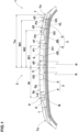
- FIG. 1 is a tire meridian cross-sectional view of a tread portion 2 of a tire 1 as an embodiment under its normal state.
- the "normal state” is a state of the tire 1 which is mounted on a normal rim and inflated to a normal internal pressure but load with no tire load.
- the "normal rim” is a wheel rim specified for the tire by a standard included in a standardization system on which the tire is based, for example, the "normal wheel rim” in JATMA, "Design Rim” in TRA, and “Measuring Rim” in ETRTO. If there is no standardization system including standards on which the tire 1 is to be based, the "normal rim” is a wheel rim specified by the tire manufacturer or the like.
- the "normal inner pressure” is air pressure specified for the tire by a standard included in a standardization system on which the tire is based, for example, the “maximum air pressure” in JATMA, maximum value listed in the "TIRE LOAD LIMITS AT VARIOUS COLD INFLATION PRESSURES" table in TRA, and "INFLATION PRESSURE” in ETRTO. If there is no standardization system including standards on which the tire 1 is to be based, the "normal inner pressure” is air pressure specified by the tire manufacturer or the like.
- the tire 1 of the present embodiment has a tread portion 2 contacting with the ground during running.
- the tread portion 2 in the present embodiment is provided with grooves 3.
- the grooves 3 include a plurality of circumferential grooves 4, in this example, four circumferential grooves 4, each extending in the tire circumferential direction, and a plurality of lateral grooves 5 extending in the tire axial direction.
- the circumferential grooves 4 in this example include a shoulder circumferential groove 4B, and a crown circumferential groove 4A disposed on the tire equator C side of the shoulder circumferential groove 4B.
- the tire 1 has good drainage property when running on wet road surfaces due to such grooves 3.
- FIG. 2 is a schematic view showing a ground contact area 2a of the tread portion 2.
- the ground contact area 2a has ground contact lengths L in the tire circumferential direction associated with respective positions P in the tire axial direction.
- the ground contact area 2a of the present embodiment has a half tread width Tw which is a distance from the tire equator C to a tread edge Te which is an outermost end of the ground contact area 2a in the tire axial direction.
- the tire equator C is the center position in the tire axial direction between the tread edges Te on both sides.
- the "normal load” is a load specified for the tire by a standard included in a standardization system on which the tire is based, for example, the “maximum load capacity” in JATMA, maximum value listed in “TIRE LOAD LIMITS AT VARIOUS COLD INFLATION PRESSURES" table in TRA, and "LOAD CAPACITY” in ETRTO. If there is no standardization system including standards on which the tire 1 is to be based, the "normal load” is a load specified by the tire manufacturer or the like.
- the ground contact lengths L include a crown ground contact length LC at the tire equator C, and a shoulder ground contact length LS at an axial position P1 spaced apart from the tire equator C by a distance w1 of 80% of the half tread width Tw.
- the crown ground contact length LC is in a range from 0.95 to 1.05 times the shoulder ground contact length LS.
- the groove depth d can be prevented from becoming excessively large for the amount of wear which is different depending on the axial positions, and the rigidity of the tread portion 2 is improved to improve the cornering power. Therefore, the tire 1 of the present embodiment can be improved in steering stability performance while maintaining the excellent wear resistance performance.
- the groove depth d0 of the reference virtual groove G0 is determined based on the groove depth d of the actual circumferential groove 4 disposed adjacently to the tire equator C. For example, by determining a curve line which extends with the same radius of curvature R as the radially outer surface 2b of the tread portion at the tire equator C while contacting with the groove bottoms of the crown circumferential grooves 4A disposed on both sides of the tire equator C adjacently thereto, the groove depth d0 of the reference virtual groove G0 is defined as the radial distance between the curve line and the radially outer surface 2b at the tire equator C.
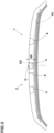
- FIG. 3 shows a meridian cross section of the tread portion 2 of the tire 1 as another embodiment under the normal state.
- the tread portion 2 of the present embodiment is provided with three circumferential grooves 4.
- One of the three circumferential grooves 4 is disposed on the tire equator C.
- the groove depth d0 of the reference virtual groove G0 of the present embodiment is defined as the groove depth d of the circumferential groove 4 arranged on the tire equator C.
- the number of the circumferential grooves 4 may be, for example, two or five or more.
- the groove depths d of the circumferential grooves 4 are preferably defined based on a virtual line VL defined in the tire meridian cross section under the normal state with no tire load as shown in FIGS. 1 and 2 .
- the virtual line VL of the present embodiment is defined based on the reference virtual groove G0, a first virtual groove G1, a second virtual groove G2, and a third virtual groove G3 defined in the tread portion 2 in the tire meridian cross section under the normal state with no tire load.
- the reference virtual groove G0 is a virtual circumferential groove defined at the tire equator C.
- the first virtual groove G1 is a virtual circumferential groove defined at a first axial position P1 spaced apart from the tire equator C in the tire axial direction.
- the second virtual groove G2 is a virtual circumferential groove defined at a second axial position P2 axially outside the first axial position P1.
- the third virtual groove G3 is a virtual circumferential groove defined at a third axial position P3 axially outside the second axial position P2.
- Such virtual line VL can optimize the groove depth d of each circumferential groove 4 for the amount of wear, and can improve the rigidity of the tread portion 2, thereby, it is possible to improve the steering stability performance of the tire 1.
- the virtual line VL helps to reduce the thickness t of the tread rubber 2g of the tread portion 2 to reduce the weight of the tire 1, thereby, it is possible to improve the low-fuel consumption performance of the tire 1.
- the thickness t of the tread rubber 2g is the distance between the radially outer surface 2b of the tread portion 2 and a tread reinforcing layer (belt) B disposed in the tread portion 2.
- the ground contact lengths L include a first ground contact length L1 at the first axial position P1, a second ground contact length L2 at the second axial position P2, and a third ground contact length L3 at the third axial position P3.
- Such first ground contact length L1, second ground contact length L2, and third ground contact length L3 are useful for accurately defining the virtual line VL.
- the correction coefficient ⁇ is preferably a positive number of 2.0 or less.
- the correction coefficient ⁇ is 2.0 or less, it is possible to suppress excessive correction caused by the differences of the first ground contact length L1, the second ground contact length L2, and the third ground contact length L3 from the crown ground contact length LC.
- correction coefficient ⁇ is a positive number, it is possible to reliably correct based on the differences of the first ground contact length L1, the second ground contact length L2, and the third ground contact length L3 from the crown ground contact length LC.
- the correction coefficient ⁇ is 0.8 to 1.2.
- the virtual line VL of the present invention is defined so as to contact with the groove bottom of the reference virtual groove G0, the groove bottom of the first virtual groove G1, the groove bottom of the second virtual groove G2, and the groove bottom of the third virtual groove G3.
- each circumferential groove 4 of the present invention is in a range from 90% to 110% of the distance Ld from the radially outer surface 2b of the tread portion 2 to the virtual line VL measured at the axial position P at which the circumferential groove 4 is formed.
- Such circumferential groove 4 is prevented from having an excessively large groove depth d for the amount of wear which is different depending on the positions P in the tire axial direction, and thereby the rigidity of the tread portion 2 is improved. Therefore, the tire 1 of the present invention can be improved in steering stability performance while maintaining the excellent wear resistance performance.
- the first axial position P1 is spaced apart from the tire equator C at an axial distance W1 of from 40% to 55% of the half tread width Tw.
- the first axial position P1 in this example is located in a middle land portion 6 defined between the crown circumferential groove 4A and the shoulder circumferential groove 4B.
- the second axial position P2 is spaced apart from the tire equator C by an axial distance W2 of from 75% to 80% of the half tread width Tw.
- the second axial position P2 in this example is located in a shoulder land portion 7 defined as extending axially outwardly from the shoulder circumferential groove 4B.
- the second ground contact length L2 is equal to the shoulder ground contact length LS.
- the third axial position P3 is spaced apart from the tire equator C by a distance W3 of from 90% to 85% of the half tread width Tw.
- the third axial position P3 in this example is located in the shoulder land portion 7 axially outside the shoulder circumferential groove 4B.
- the virtual line VL can be accurately defined over the entire range from the tire equator C to the tread edge Te.
- the circumferential grooves 4 in the present embodiment include an axially inner first circumferential groove, and an axially outer second circumferential groove.
- the first circumferential groove is, for example, the crown circumferential groove 4A.
- the second circumferential groove is, for example, the shoulder circumferential groove 4B.
- the groove depth of the second circumferential groove is larger than the groove depth of the first circumferential groove.
- the groove depth d of the lateral groove 5 at an axial position P is equal to or less than the distance Ld from the radially outer surface 2b to the virtual line VL at the axial position P.
- the virtual line VL can optimize the maximum value for the groove depth d of the lateral groove 5.
- the groove bottom of the lateral groove 5 may extend along the virtual line VL.
- FIG. 4 is a flowchart of the groove depth setting method according to the present embodiment.
- the ground contact area 2a may be determined through a simulation using a computer, or an experiment.
- the shape of the ground contact area 2a is obtained accurately.
- the first ground contact length L1, the second ground contact length L2, and the third ground contact length L3 are obtained.
- the third step S3 defines the groove depth d0 of the reference virtual groove G0, the groove depth d1 of the first virtual groove G1, the groove depth d2 of the second virtual groove G2, and the groove depth d3 of the third virtual groove G3.
- the groove depth d of the circumferential groove 4 can be optimized for the amount of wear which is different depending on the axial positions, and thereby the rigidity of the tread portion 2 can be improved. Therefore, the groove depth setting method can improve the steering stability performance while maintaining the excellent wear resistance performance of the tire 1.
- the groove depth setting method for example, it may be possible to define the virtual line VL by using virtual circles defined so as to have respective centers on the radially outer surface 2b of the tread portion 2, instead of the virtual grooves.
- pneumatic tires having circumferential grooves were experimentally manufactured as test tires including working examples and comparative example.
- the groove depths of the circumferential grooves were determined based on the equations (2) to 4).
- the circumferential grooves had the same groove depth.
- the tires were tested for the wear resistance performance, steering stability performance, noise performance and low-fuel consumption performance.
- Each test tire was attached to all wheels of a test vehicle, and after the vehicle had run for 20000 km on a dry paved road surface, tread wear was measured at different axial positions to obtain the amount of wear at the axial position where the wear was most progressed.
- Each test tire was attached to all wheels of a test vehicle, and the pass-by noise was measured outside the test vehicle when running on a noise measuring road surface of a tire test course.
- the weight of each test tire was measured.
Landscapes
- Engineering & Computer Science (AREA)
- Mechanical Engineering (AREA)
- Tires In General (AREA)
Description
- The present invention relates to a tire having a tread portion.
- Conventionally, a tire having a tread portion provided with circumferential grooves extending in the tire circumferential direction has been known.
- For example, Patent Document 1 below discloses a tire improved in wear resistance by specifically defining the profile of a tread portion in which a plurality of main grooves extending in the tire circumferential direction are formed.
Patent Document 1:Japanese Patent Application Publication No. 2019-182339 - A tire in accordance with the preamble of claim 1 is known from
US 6 443 199 B1 andJP 2009 078790 A EP 3 173 254 A1EP 2 527 163 A1EP 3 689 642 A1 - In the tire of Patent Document 1, since the groove depths of the main grooves are the same and relatively large, the rigidity of the tread portion is reduced by the main grooves, therefore, the tire is required to be improved in the rigidity of the tread portion in view of the steering stability performance.
- In view of the above circumstances, the present invention was made, and a main object of the present invention is to provide a tire in which steering stability performance can be improved, while maintaining excellent wear resistance performance.
- The object is solved by a tire having the features of claim 1. Sub-claims are directed to preferable embodiments of the invention.
- In the tire according to the present invention, as the crown ground contact length is 0.95 to 1.05 times the shoulder ground contact length, the tire has a large ground contact area and can improve cornering power, therefore, it is possible to improve steering stability performance.
Further, as the groove depth d of each grooves is determined so as to satisfy the above equation (1), the groove depth can be prevented from becoming excessively large for the amount of wear which is different depending on the axial position. As a result, the rigidity of the tread portion is improved, and the cornering power can be improved. Therefore, the tire of the present invention can be improved in steering stability performance while maintaining excellent wear resistance performance. -
-
FIG. 1 is a cross-sectional view of a tread portion of a tire as an embodiment of the present invention. -
FIG. 2 is a diagram showing a ground contact area or footprint of the tire. -
FIG. 3 is a cross-sectional view of a tread portion of a tire as another embodiment of the present invention. -
FIG. 4 is a flowchart showing a method of setting a groove depth as an embodiment of the present invention. - The present invention can be applied to various tires such as a pneumatic tire for passenger cars, a pneumatic tire for heavy load vehicles, a pneumatic tire for two-wheeled vehicles, a non-pneumatic tire so called airless tire and the like. In particular, the present invention is suitably applied to a pneumatic tire for passenger cars.
- Taking a pneumatic tire for passenger cars as an example, an embodiment of the present invention will now be described in detail in conjunction with accompanying drawings.
-
FIG. 1 is a tire meridian cross-sectional view of atread portion 2 of a tire 1 as an embodiment under its normal state. - Here, when the tire 1 is a pneumatic tire, the "normal state" is a state of the tire 1 which is mounted on a normal rim and inflated to a normal internal pressure but load with no tire load.
- In the present specification, the dimensions and the like of portions of the tire 1 are values measured in the normal state unless otherwise noted.
- The "normal rim" is a wheel rim specified for the tire by a standard included in a standardization system on which the tire is based, for example, the "normal wheel rim" in JATMA, "Design Rim" in TRA, and "Measuring Rim" in ETRTO. If there is no standardization system including standards on which the tire 1 is to be based, the "normal rim" is a wheel rim specified by the tire manufacturer or the like.
- The "normal inner pressure" is air pressure specified for the tire by a standard included in a standardization system on which the tire is based, for example, the "maximum air pressure" in JATMA, maximum value listed in the "TIRE LOAD LIMITS AT VARIOUS COLD INFLATION PRESSURES" table in TRA, and "INFLATION PRESSURE" in ETRTO. If there is no standardization system including standards on which the tire 1 is to be based, the "normal inner pressure" is air pressure specified by the tire manufacturer or the like.
- As shown in
FIG. 1 , the tire 1 of the present embodiment has atread portion 2 contacting with the ground during running. Thetread portion 2 in the present embodiment is provided with grooves 3.In the present embodiment, thegrooves 3 include a plurality ofcircumferential grooves 4, in this example, fourcircumferential grooves 4, each extending in the tire circumferential direction, and a plurality oflateral grooves 5 extending in the tire axial direction. - The
circumferential grooves 4 in this example include a shouldercircumferential groove 4B, and a crowncircumferential groove 4A disposed on the tire equator C side of the shouldercircumferential groove 4B.
the tire 1 has good drainage property when running on wet road surfaces due tosuch grooves 3. -
FIG. 2 is a schematic view showing aground contact area 2a of thetread portion 2. - As shown in
FIG. 2 , in thetread portion 2 of the present embodiment, when the tire under the normal state is contacted with a horizontal flat plane at a camber angle of 0 degree and loaded with a normal load,
theground contact area 2a has ground contact lengths L in the tire circumferential direction associated with respective positions P in the tire axial direction. - The
ground contact area 2a of the present embodiment has a half tread width Tw which is a distance from the tire equator C to a tread edge Te which is an outermost end of theground contact area 2a in the tire axial direction. - The tire equator C is the center position in the tire axial direction between the tread edges Te on both sides.
- Here, the "normal load" is a load specified for the tire by a standard included in a standardization system on which the tire is based, for example, the "maximum load capacity" in JATMA, maximum value listed in "TIRE LOAD LIMITS AT VARIOUS COLD INFLATION PRESSURES" table in TRA, and "LOAD CAPACITY" in ETRTO. If there is no standardization system including standards on which the tire 1 is to be based, the "normal load" is a load specified by the tire manufacturer or the like.
- The ground contact lengths L include a crown ground contact length LC at the tire equator C, and a shoulder ground contact length LS at an axial position P1 spaced apart from the tire equator C by a distance w1 of 80% of the half tread width Tw. In the present embodiment, the crown ground contact length LC is in a range from 0.95 to 1.05 times the shoulder ground contact length LS.
- Since such tire 1 has a large ground contact area and can improve cornering power, it is possible to improve steering stability performance.
- Based on a groove depth d0 predetermined for a reference virtual groove G0 defined at the axial position of the tire equator C as shown in
FIGS. 1 and2 ,
the depth d of each of thegrooves 3 at an axial position is determined so as to satisfy the following equation (1):
- L is the ground contact length of the
ground contact area 2a measured at the above-said axial position, - LC is the crown ground contact length at the tire equator C, and
- α: a correction coefficient.
- In
such groove 3, the groove depth d can be prevented from becoming excessively large for the amount of wear which is different depending on the axial positions, and the rigidity of thetread portion 2 is improved to improve the cornering power. Therefore, the tire 1 of the present embodiment can be improved in steering stability performance while maintaining the excellent wear resistance performance. - Preferably, the groove depth d0 of the reference virtual groove G0 is determined based on the groove depth d of the actual
circumferential groove 4 disposed adjacently to the tire equator C. For example, by determining a curve line which extends with the same radius of curvature R as the radiallyouter surface 2b of the tread portion at the tire equator C while contacting with the groove bottoms of the crowncircumferential grooves 4A disposed on both sides of the tire equator C adjacently thereto,
the groove depth d0 of the reference virtual groove G0 is defined as the radial distance between the curve line and the radiallyouter surface 2b at the tire equator C. -
FIG. 3 shows a meridian cross section of thetread portion 2 of the tire 1 as another embodiment under the normal state. - As shown in
FIG. 3 , thetread portion 2 of the present embodiment is provided with threecircumferential grooves 4. - One of the three
circumferential grooves 4 is disposed on the tire equator C. - The groove depth d0 of the reference virtual groove G0 of the present embodiment is defined as the groove depth d of the
circumferential groove 4 arranged on the tire equator C. - The definition of the groove depth d0 of such reference virtual groove G0 is simple and clear.
- The number of the
circumferential grooves 4 may be, for example, two or five or more. - The groove depths d of the
circumferential grooves 4 are preferably defined based on a virtual line VL defined in the tire meridian cross section under the normal state with no tire load as shown inFIGS. 1 and2 . - The virtual line VL of the present embodiment is defined based on the reference virtual groove G0, a first virtual groove G1, a second virtual groove G2, and a third virtual groove G3 defined in the
tread portion 2 in the tire meridian cross section under the normal state with no tire load. - The reference virtual groove G0 is a virtual circumferential groove defined at the tire equator C.
- The first virtual groove G1 is a virtual circumferential groove defined at a first axial position P1 spaced apart from the tire equator C in the tire axial direction.
- The second virtual groove G2 is a virtual circumferential groove defined at a second axial position P2 axially outside the first axial position P1.
- The third virtual groove G3 is a virtual circumferential groove defined at a third axial position P3 axially outside the second axial position P2.
- such virtual line VL can optimize the groove depth d of each
circumferential groove 4 for the amount of wear, and can improve the rigidity of thetread portion 2, thereby, it is possible to improve the steering stability performance of the tire 1. - Further, the virtual line VL helps to reduce the thickness t of the
tread rubber 2g of thetread portion 2 to reduce the weight of the tire 1, thereby, it is possible to improve the low-fuel consumption performance of the tire 1. - Here, the thickness t of the
tread rubber 2g is the distance between the radiallyouter surface 2b of thetread portion 2 and a tread reinforcing layer (belt) B disposed in thetread portion 2. - The ground contact lengths L include a first ground contact length L1 at the first axial position P1, a second ground contact length L2 at the second axial position P2, and a third ground contact length L3 at the third axial position P3.
- Such first ground contact length L1, second ground contact length L2, and third ground contact length L3 are useful for accurately defining the virtual line VL.
- The groove depth d1 of the first virtual groove G1 is preferably determined by the following equation (2):

- d0 is the groove depth of the reference virtual groove,
- LC is the crown ground contact length,
- L1 is the first ground contact length, and
- α is the correction coefficient.
- The groove depth d2 of the second virtual groove G2 is preferably determined by the following equation (3):

- d0 is the groove depth of the reference virtual groove,
- LC is the crown ground contact length,
- L2 is the second ground contact length, and
- α is the correction coefficient.
- The groove depth d3 of the third virtual groove G3 is preferably determined by the following equation (4):

- d0 is the groove depth of the reference virtual groove,
- LC is the crown ground contact length,
- L3 is the third ground contact length, and
- α is the correction coefficient.
- The correction coefficient α is preferably a positive number of 2.0 or less.
- As the correction coefficient α is 2.0 or less, it is possible to suppress excessive correction caused by the differences of the first ground contact length L1, the second ground contact length L2, and the third ground contact length L3 from the crown ground contact length LC.
- As the correction coefficient α is a positive number, it is possible to reliably correct based on the differences of the first ground contact length L1, the second ground contact length L2, and the third ground contact length L3 from the crown ground contact length LC.
- More preferably, the correction coefficient α is 0.8 to 1.2.
- The virtual line VL of the present invention is defined so as to contact with the groove bottom of the reference virtual groove G0, the groove bottom of the first virtual groove G1, the groove bottom of the second virtual groove G2, and the groove bottom of the third virtual groove G3.
- The groove depth d of each
circumferential groove 4 of the present invention is in a range from 90% to 110% of the distance Ld from the radiallyouter surface 2b of thetread portion 2 to the virtual line VL measured at the axial position P at which thecircumferential groove 4 is formed. - Such
circumferential groove 4 is prevented from having an excessively large groove depth d for the amount of wear which is different depending on the positions P in the tire axial direction, and thereby the rigidity of thetread portion 2 is improved. Therefore, the tire 1 of the present invention can be improved in steering stability performance while maintaining the excellent wear resistance performance. - The first axial position P1 is spaced apart from the tire equator C at an axial distance W1 of from 40% to 55% of the half tread width Tw.
- The first axial position P1 in this example is located in a
middle land portion 6 defined between thecrown circumferential groove 4A and the shouldercircumferential groove 4B. - The second axial position P2 is spaced apart from the tire equator C by an axial distance W2 of from 75% to 80% of the half tread width Tw.
- The second axial position P2 in this example is located in a
shoulder land portion 7 defined as extending axially outwardly from the shouldercircumferential groove 4B. - When the axial distance W2 is 80% of the half tread width Tw, the second ground contact length L2 is equal to the shoulder ground contact length LS.
- The third axial position P3 is spaced apart from the tire equator C by a distance W3 of from 90% to 85% of the half tread width Tw.
- The third axial position P3 in this example is located in the
shoulder land portion 7 axially outside the shouldercircumferential groove 4B. - By the reference virtual groove G0, the first virtual groove G1, the second virtual groove G2, and the third virtual groove G3, the virtual line VL can be accurately defined over the entire range from the tire equator C to the tread edge Te.
- The
circumferential grooves 4 in the present embodiment include an axially inner first circumferential groove, and an axially outer second circumferential groove. - The first circumferential groove is, for example, the
crown circumferential groove 4A. The second circumferential groove is, for example, the shouldercircumferential groove 4B. - In the present invention, the groove depth of the second circumferential groove is larger than the groove depth of the first circumferential groove.
- In such
circumferential grooves 4, when thetread portion 2 is worn, the remaining groove depths become almost equal. As a result, it is possible to achieve the durability performance as well as the low-fuel consumption performance owing to weight reduction. - In the present embodiment, the groove depth d of the
lateral groove 5 at an axial position P is equal to or less than the distance Ld from the radiallyouter surface 2b to the virtual line VL at the axial position P. The virtual line VL can optimize the maximum value for the groove depth d of thelateral groove 5. The groove bottom of thelateral groove 5 may extend along the virtual line VL. - Next, for the tire 1 whose tread portion is provided with a plurality of
circumferential grooves 4 extending in the tire circumferential direction, a method of setting the groove depth d of thecircumferential groove 4 is described with reference toFIGS. 1 to 3 . -
FIG. 4 is a flowchart of the groove depth setting method according to the present embodiment. - In this method, as shown in
FIG. 4 , a first step S1 of determining theground contact area 2a of thetread portion 2 when the tire 1 under the normal state is contacted with a horizontal flat plane at a camber angle of 0 degree and loaded with a normal load, is performed. - In the first step S1, the
ground contact area 2a may be determined through a simulation using a computer, or an experiment. - In the first step S1, the shape of the
ground contact area 2a is obtained accurately. - In the groove depth setting method of the present embodiment, after the first step 51, there is performed a second step S2 of obtaining the ground contact length L in the tire circumferential direction of the
ground contact area 2a associated with each position P in the tire axial direction of theground contact area 2a. - In the second step S2 of the present embodiment, at least the crown ground contact length LC and the shoulder ground contact length LS are obtained.
- In the second step S2, it is desirable that the first ground contact length L1, the second ground contact length L2, and the third ground contact length L3 are obtained.
- In the second step S2, it is not necessary to obtain the ground contact length L associated with all positions P in the tire axial direction to shorten the calculation time.
- In the groove depth setting method of the present embodiment, after the second step S2, performed is a third step S3 of defining the reference virtual groove G0, the first virtual groove G1, the second virtual groove G2, and the third virtual groove G3.
- In this example, the third step S3 defines the groove depth d0 of the reference virtual groove G0, the groove depth d1 of the first virtual groove G1, the groove depth d2 of the second virtual groove G2, and the groove depth d3 of the third virtual groove G3.
- In the groove depth setting method of the present embodiment, after the third step S3, there is performed a fourth step S4 of defining the virtual line VL by a tangential line contacting with the groove bottom of the reference virtual groove G0, the groove bottom of the first virtual groove G1, the groove bottom of the second virtual groove G2, and the groove bottom of the third virtual groove G3.
- In the groove depth setting method of the present embodiment, after the fourth step S4, there is performed a fifth step S5 of determining the groove depth d of each
circumferential groove 4 so that the groove bottom is located on the virtual line VL. - In such groove depth setting method, the groove depth d of the
circumferential groove 4 can be optimized for the amount of wear which is different depending on the axial positions, and thereby the rigidity of thetread portion 2 can be improved. Therefore, the groove depth setting method can improve the steering stability performance while maintaining the excellent wear resistance performance of the tire 1. - In the groove depth setting method, for example, it may be possible to define the virtual line VL by using virtual circles defined so as to have respective centers on the radially
outer surface 2b of thetread portion 2, instead of the virtual grooves. - While detailed description has been made of preferable embodiments of the present invention, the present invention can be embodied in various forms within the scope of the appended claims.
- Based on the structure shown in
FIG. 1 , pneumatic tires having circumferential grooves were experimentally manufactured as test tires including working examples and comparative example. In the working examples, the groove depths of the circumferential grooves were determined based on the equations (2) to 4). - In the comparative example, the circumferential grooves had the same groove depth.
- The specifications are shown in Table 1.
- The tires were tested for the wear resistance performance, steering stability performance, noise performance and low-fuel consumption performance.
- The common specifications of the test tires and test methods are as follows.
-
- Tire size: 255/65R18
- Rim size: 18x7.5J
- Each test tire was attached to all wheels of a test vehicle, and after the vehicle had run for 20000 km on a dry paved road surface, tread wear was measured at different axial positions to obtain the amount of wear at the axial position where the wear was most progressed.
- The obtained results are indicated in Table 1 by an index based on Comparative Example being 100, wherein the larger the value, the less the wear progresses, namely, the better the wear resistance performance.
- Using a flat belt tester, the cornering power of each test tire was measured when the tire mounted on a normal rim, inflated to a normal internal pressure and load with a normal tire load was running on the belt with a slip angle of 1 degree at a speed of 30 km/h.
- The results are indicated in Table 1 by an index based on Comparative Example being 100, wherein the larger the value, the larger the cornering power, namely, the better the steering stability performance.
- Each test tire was attached to all wheels of a test vehicle, and the pass-by noise was measured outside the test vehicle when running on a noise measuring road surface of a tire test course.
- The results are indicated in Table 1 by an index based on Comparative Example being 100, wherein the larger the value, the smaller the noise, namely, the better the noise performance.
- The weight of each test tire was measured.
- The results are indicated in Table 1 by an index based on Comparative Example being 100, wherein the larger the value, the lighter the weight, namely, the better the low-fuel consumption performance.
Table 1 tire comparative example working example 1 working example 2 working example 3 Correction coefficient α -- 0.1 1.0 2.0 Wear resistance performance 100 100 100 100 Steering stability performance 100 103 105 103 Noise performance 100 103 105 103 Low-fuel consumption performance 100 103 105 103 - Form the test results, it was confirmed that, as compared with the comparative example, the tires according to the present invention were improved in steering stability performance while maintaining comparable wear resistance performance, and exhibited excellent noise performance and low-fuel consumption performance.
-
- 1 tire
- 2 tread portion
- 2a ground contact area
- 3 groove
- 4 circumferential groove
- 5 lateral groove
Claims (3)
- A tire (1) comprising a tread portion (2) provided with grooves (3, 4),
wherein
when the tire mounted on a normal rim and inflated to a normal internal pressure is contacted with a horizontal flat surface at a camber angle of 0 degree and loaded with a normal load,the tread portion (2) has a ground contact area (2a) having ground contact lengths (L) in the tire circumferential direction associated with respective positions in the tire axial direction, anda half tread width (Tw) which is a distance from the tire equator (C) to a tread edge (Te) which is the axially outermost end of the ground contact area (2a),
the ground contact lengths (L) includea crown ground contact length LC at the tire equator (C), anda shoulder ground contact length (LS) at a position spaced apart from the tire equator (C) by an axial distance of 80% of the half tread width (Tw),whereinthe crown ground contact length LC is 0.95 to 1.05 times the shoulder ground contact length (LS),characterized in thatin a meridian cross section of the tire mounted on the normal rim, inflated to the normal internal pressure and loaded with no tire load,given a groove depth d0 for a reference virtual groove (G0) defined at the axial position of the tire equator (C),a groove depth d of each of the grooves at an axial position satisfies the following equation (1); whereind0 is determined based on the groove depth of an circumferential groove (4) disposed adjacently to the tire equator (C), with the groove depth d0 being defined as the radial distance between a curve line and a radially outer surface (2b) of the tread portion (2) at the tire equator (C), wherein the curve line extends with a same radius of curvature (R) as a radially outer surface (2b) of the tread portion (2) at the tire equator (C) while contacting with a groove bottom of said circumferential groove (4),LC is the crown ground contact length at the tire equator (C),L is the ground contact length of the ground contact area measured at said axial position when the tire mounted on a normal rim and inflated to a normal internal pressure is contacted with a horizontal flat surface at a camber angle of 0 degree and loaded with a normal load,α: a correction coefficient, wherein the correction coefficient α is a positive number of 2.0 or less,and the grooves include circumferential grooves (4) extending in the tire circumferential direction, wherein the circumferential grooves (4) include an axially inner first circumferential groove and an axially outer second circumferential groove, wherein the groove depth of the second circumferential groove is larger than the groove depth of the first circumferential groove,and wherein, in a meridian cross section of the tire mounted on the normal rim, inflated to the normal internal pressure and loaded with no tire load,whenthe reference virtual groove (G0) is defined,a first virtual groove (G1) is defined at a first axial position (P1) spaced apart from the tire equator in the tire axial direction,a second virtual groove (G2) is defined at a second axial position (P2) axially outside the first axial position,a third virtual groove (G3) is defined at a third axial position (P3) axially outside the second axial position, wherein the first axial position (P1) is spaced apart from the tire equator (C) by an axial distance (W1) of from 40% to 55% of the half tread width (Tw), the second axial position (P2) is spaced apart from the tire equator (C) by an axial distance (W2) of from 75% to 80% of the half tread width (Tw), and the third axial position (P3) is spaced apart from the tire equator (C) by an axial distance (W3) of from 90% to 85% of the half tread width (Tw), anda virtual line (VL) is defined so as to contact with a groove bottom of the reference virtual groove (G0), a groove bottom of the first virtual groove (G1), a groove bottom of the second virtual groove (G2), and a groove bottom of the third virtual groove (G3),then
the groove depth of each circumferential groove is in a range from 90% to 110% of the distance (Ld) from the radially outer surface of the tread portion (2b) to the virtual line (VL) at the axial position of said each circumferential groove,whereinthe groove depth d1 of the first virtual groove (G1),the groove depth d2 of the second virtual groove (G2), andthe groove depth d3 of the third virtual groove (G3) are determined based on the following equations (2) to (4):

 whereind0 is the groove depth of the reference virtual groove (G0),LC is the crown ground contact length,L1 is a first ground contact length at the first axial position (P1),L2 is a second ground contact length at the second axial position (P2), andL3 is a third ground contact length at the third axial position (P3), wherein the ground contact lengths LC, L1, L2 and L3 are measured when the tire mounted on a normal rim and inflated to a normal internal pressure is contacted with a horizontal flat surface at a camber angle of 0 degree and loaded with a normal load.
 - The tire (1) according to claim 1, wherein
the correction coefficient α is in a range from 0.8 to 1.2. - The tire (1) according to claim 1 or 2, wherein
the grooves include lateral grooves (5) extending in the tire axial direction.
Applications Claiming Priority (1)
| Application Number | Priority Date | Filing Date | Title |
|---|---|---|---|
| JP2020209584A JP7725819B2 (en) | 2020-12-17 | 2020-12-17 | tire |
Publications (2)
| Publication Number | Publication Date |
|---|---|
| EP4015244A1 EP4015244A1 (en) | 2022-06-22 |
| EP4015244B1 true EP4015244B1 (en) | 2023-12-06 |
Family
ID=78516526
Family Applications (1)
| Application Number | Title | Priority Date | Filing Date |
|---|---|---|---|
| EP21203439.1A Active EP4015244B1 (en) | 2020-12-17 | 2021-10-19 | Tire |
Country Status (4)
| Country | Link |
|---|---|
| US (1) | US20220194138A1 (en) |
| EP (1) | EP4015244B1 (en) |
| JP (1) | JP7725819B2 (en) |
| CN (1) | CN114643806A (en) |
Family Cites Families (22)
| Publication number | Priority date | Publication date | Assignee | Title |
|---|---|---|---|---|
| FR2128232B1 (en) * | 1971-03-12 | 1973-12-07 | Uniroyal | |
| JPH03136909A (en) * | 1989-10-23 | 1991-06-11 | Bridgestone Corp | Pneumatic tire with reduced noise characteristic |
| JP3559378B2 (en) * | 1996-02-29 | 2004-09-02 | 株式会社ブリヂストン | Pneumatic tire pair |
| US6443199B1 (en) * | 1997-09-17 | 2002-09-03 | The Goodyear Tire & Rubber Company | Footprints for nonrotatable automobile and light truck tires |
| JP4028279B2 (en) | 2002-04-08 | 2007-12-26 | 株式会社ブリヂストン | Heavy duty radial tire |
| JP2009078790A (en) * | 2007-09-27 | 2009-04-16 | Yokohama Rubber Co Ltd:The | Pneumatic radial tire |
| DE102008055498B4 (en) * | 2008-12-10 | 2015-09-17 | Continental Reifen Deutschland Gmbh | Vehicle tires |
| JP5337196B2 (en) | 2011-04-27 | 2013-11-06 | 住友ゴム工業株式会社 | Pneumatic tire |
| EP2527163B1 (en) * | 2011-05-26 | 2014-07-16 | Continental Reifen Deutschland GmbH | Pneumatic tyre for a vehicle |
| CN103874590B (en) * | 2011-08-12 | 2015-09-09 | 横滨橡胶株式会社 | pneumatic tire |
| CN103863016B (en) | 2012-12-12 | 2017-09-08 | 住友橡胶工业株式会社 | Pneumatic tire |
| JP5728035B2 (en) * | 2013-01-24 | 2015-06-03 | 住友ゴム工業株式会社 | Pneumatic tire |
| JP5886816B2 (en) | 2013-12-06 | 2016-03-16 | 住友ゴム工業株式会社 | Heavy duty tire |
| JP2015037943A (en) | 2014-11-26 | 2015-02-26 | 株式会社ブリヂストン | Pneumatic tire |
| DE102015223537A1 (en) * | 2015-11-27 | 2017-06-01 | Continental Reifen Deutschland Gmbh | Vehicle tires |
| EP3388259B1 (en) * | 2015-12-07 | 2020-02-05 | Bridgestone Corporation | Tire |
| JP6879086B2 (en) * | 2017-07-04 | 2021-06-02 | 住友ゴム工業株式会社 | Pneumatic tires |
| JP7167475B2 (en) | 2018-04-16 | 2022-11-09 | 住友ゴム工業株式会社 | tire |
| JP7155687B2 (en) | 2018-07-11 | 2022-10-19 | 横浜ゴム株式会社 | pneumatic tire |
| JP7172476B2 (en) | 2018-11-12 | 2022-11-16 | 横浜ゴム株式会社 | pneumatic tire |
| JP7225824B2 (en) * | 2019-01-22 | 2023-02-21 | 住友ゴム工業株式会社 | tire |
| JP2022096465A (en) * | 2020-12-17 | 2022-06-29 | 住友ゴム工業株式会社 | tire |
-
2020
- 2020-12-17 JP JP2020209584A patent/JP7725819B2/en active Active
-
2021
- 2021-10-19 EP EP21203439.1A patent/EP4015244B1/en active Active
- 2021-11-17 CN CN202111363000.4A patent/CN114643806A/en active Pending
- 2021-12-02 US US17/540,493 patent/US20220194138A1/en not_active Abandoned
Also Published As
| Publication number | Publication date |
|---|---|
| JP7725819B2 (en) | 2025-08-20 |
| CN114643806A (en) | 2022-06-21 |
| US20220194138A1 (en) | 2022-06-23 |
| EP4015244A1 (en) | 2022-06-22 |
| JP2022096466A (en) | 2022-06-29 |
Similar Documents
| Publication | Publication Date | Title |
|---|---|---|
| US10239358B2 (en) | Pneumatic tire | |
| EP2610085B1 (en) | Pneumatic tire | |
| US11511567B2 (en) | Tyre | |
| EP3269564A1 (en) | Pneumatic tire | |
| US11312183B2 (en) | Pneumatic tyre | |
| EP2881266B1 (en) | Pneumatic tire | |
| US11571934B2 (en) | Tire | |
| EP3332991B1 (en) | Pneumatic tire | |
| US10953701B2 (en) | Tire | |
| US11104182B2 (en) | Tire | |
| US20220063344A1 (en) | Tire | |
| EP3536521B1 (en) | Tyre | |
| EP4015245A1 (en) | Tire | |
| EP3967520B1 (en) | Tire having tread grooves | |
| EP3967521B1 (en) | Tire having tread grooves and method for configuring groove depths | |
| EP4015244B1 (en) | Tire | |
| EP3666552B1 (en) | Tyre | |
| US20190308467A1 (en) | Tyre |
Legal Events
| Date | Code | Title | Description |
|---|---|---|---|
| PUAI | Public reference made under article 153(3) epc to a published international application that has entered the european phase |
Free format text: ORIGINAL CODE: 0009012 |
|
| STAA | Information on the status of an ep patent application or granted ep patent |
Free format text: STATUS: THE APPLICATION HAS BEEN PUBLISHED |
|
| AK | Designated contracting states |
Kind code of ref document: A1 Designated state(s): AL AT BE BG CH CY CZ DE DK EE ES FI FR GB GR HR HU IE IS IT LI LT LU LV MC MK MT NL NO PL PT RO RS SE SI SK SM TR |
|
| STAA | Information on the status of an ep patent application or granted ep patent |
Free format text: STATUS: REQUEST FOR EXAMINATION WAS MADE |
|
| 17P | Request for examination filed |
Effective date: 20220908 |
|
| RBV | Designated contracting states (corrected) |
Designated state(s): AL AT BE BG CH CY CZ DE DK EE ES FI FR GB GR HR HU IE IS IT LI LT LU LV MC MK MT NL NO PL PT RO RS SE SI SK SM TR |
|
| STAA | Information on the status of an ep patent application or granted ep patent |
Free format text: STATUS: EXAMINATION IS IN PROGRESS |
|
| 17Q | First examination report despatched |
Effective date: 20230313 |
|
| GRAP | Despatch of communication of intention to grant a patent |
Free format text: ORIGINAL CODE: EPIDOSNIGR1 |
|
| STAA | Information on the status of an ep patent application or granted ep patent |
Free format text: STATUS: GRANT OF PATENT IS INTENDED |
|
| INTG | Intention to grant announced |
Effective date: 20230818 |
|
| GRAS | Grant fee paid |
Free format text: ORIGINAL CODE: EPIDOSNIGR3 |
|
| GRAA | (expected) grant |
Free format text: ORIGINAL CODE: 0009210 |
|
| STAA | Information on the status of an ep patent application or granted ep patent |
Free format text: STATUS: THE PATENT HAS BEEN GRANTED |
|
| AK | Designated contracting states |
Kind code of ref document: B1 Designated state(s): AL AT BE BG CH CY CZ DE DK EE ES FI FR GB GR HR HU IE IS IT LI LT LU LV MC MK MT NL NO PL PT RO RS SE SI SK SM TR |
|
| REG | Reference to a national code |
Ref country code: GB Ref legal event code: FG4D |
|
| REG | Reference to a national code |
Ref country code: DE Ref legal event code: R096 Ref document number: 602021007463 Country of ref document: DE |
|
| REG | Reference to a national code |
Ref country code: CH Ref legal event code: EP |
|
| REG | Reference to a national code |
Ref country code: IE Ref legal event code: FG4D |
|
| REG | Reference to a national code |
Ref country code: LT Ref legal event code: MG9D |
|
| PG25 | Lapsed in a contracting state [announced via postgrant information from national office to epo] |
Ref country code: GR Free format text: LAPSE BECAUSE OF FAILURE TO SUBMIT A TRANSLATION OF THE DESCRIPTION OR TO PAY THE FEE WITHIN THE PRESCRIBED TIME-LIMIT Effective date: 20240307 |
|
| REG | Reference to a national code |
Ref country code: NL Ref legal event code: MP Effective date: 20231206 |
|
| PG25 | Lapsed in a contracting state [announced via postgrant information from national office to epo] |
Ref country code: LT Free format text: LAPSE BECAUSE OF FAILURE TO SUBMIT A TRANSLATION OF THE DESCRIPTION OR TO PAY THE FEE WITHIN THE PRESCRIBED TIME-LIMIT Effective date: 20231206 |
|
| PG25 | Lapsed in a contracting state [announced via postgrant information from national office to epo] |
Ref country code: ES Free format text: LAPSE BECAUSE OF FAILURE TO SUBMIT A TRANSLATION OF THE DESCRIPTION OR TO PAY THE FEE WITHIN THE PRESCRIBED TIME-LIMIT Effective date: 20231206 |
|
| PG25 | Lapsed in a contracting state [announced via postgrant information from national office to epo] |
Ref country code: LT Free format text: LAPSE BECAUSE OF FAILURE TO SUBMIT A TRANSLATION OF THE DESCRIPTION OR TO PAY THE FEE WITHIN THE PRESCRIBED TIME-LIMIT Effective date: 20231206 Ref country code: GR Free format text: LAPSE BECAUSE OF FAILURE TO SUBMIT A TRANSLATION OF THE DESCRIPTION OR TO PAY THE FEE WITHIN THE PRESCRIBED TIME-LIMIT Effective date: 20240307 Ref country code: ES Free format text: LAPSE BECAUSE OF FAILURE TO SUBMIT A TRANSLATION OF THE DESCRIPTION OR TO PAY THE FEE WITHIN THE PRESCRIBED TIME-LIMIT Effective date: 20231206 Ref country code: BG Free format text: LAPSE BECAUSE OF FAILURE TO SUBMIT A TRANSLATION OF THE DESCRIPTION OR TO PAY THE FEE WITHIN THE PRESCRIBED TIME-LIMIT Effective date: 20240306 |
|
| REG | Reference to a national code |
Ref country code: AT Ref legal event code: MK05 Ref document number: 1638050 Country of ref document: AT Kind code of ref document: T Effective date: 20231206 |
|
| PG25 | Lapsed in a contracting state [announced via postgrant information from national office to epo] |
Ref country code: NL Free format text: LAPSE BECAUSE OF FAILURE TO SUBMIT A TRANSLATION OF THE DESCRIPTION OR TO PAY THE FEE WITHIN THE PRESCRIBED TIME-LIMIT Effective date: 20231206 |
|
| PG25 | Lapsed in a contracting state [announced via postgrant information from national office to epo] |
Ref country code: SE Free format text: LAPSE BECAUSE OF FAILURE TO SUBMIT A TRANSLATION OF THE DESCRIPTION OR TO PAY THE FEE WITHIN THE PRESCRIBED TIME-LIMIT Effective date: 20231206 Ref country code: RS Free format text: LAPSE BECAUSE OF FAILURE TO SUBMIT A TRANSLATION OF THE DESCRIPTION OR TO PAY THE FEE WITHIN THE PRESCRIBED TIME-LIMIT Effective date: 20231206 Ref country code: NO Free format text: LAPSE BECAUSE OF FAILURE TO SUBMIT A TRANSLATION OF THE DESCRIPTION OR TO PAY THE FEE WITHIN THE PRESCRIBED TIME-LIMIT Effective date: 20240306 Ref country code: NL Free format text: LAPSE BECAUSE OF FAILURE TO SUBMIT A TRANSLATION OF THE DESCRIPTION OR TO PAY THE FEE WITHIN THE PRESCRIBED TIME-LIMIT Effective date: 20231206 Ref country code: LV Free format text: LAPSE BECAUSE OF FAILURE TO SUBMIT A TRANSLATION OF THE DESCRIPTION OR TO PAY THE FEE WITHIN THE PRESCRIBED TIME-LIMIT Effective date: 20231206 Ref country code: HR Free format text: LAPSE BECAUSE OF FAILURE TO SUBMIT A TRANSLATION OF THE DESCRIPTION OR TO PAY THE FEE WITHIN THE PRESCRIBED TIME-LIMIT Effective date: 20231206 |
|
| PG25 | Lapsed in a contracting state [announced via postgrant information from national office to epo] |
Ref country code: IS Free format text: LAPSE BECAUSE OF FAILURE TO SUBMIT A TRANSLATION OF THE DESCRIPTION OR TO PAY THE FEE WITHIN THE PRESCRIBED TIME-LIMIT Effective date: 20240406 |
|
| PG25 | Lapsed in a contracting state [announced via postgrant information from national office to epo] |
Ref country code: CZ Free format text: LAPSE BECAUSE OF FAILURE TO SUBMIT A TRANSLATION OF THE DESCRIPTION OR TO PAY THE FEE WITHIN THE PRESCRIBED TIME-LIMIT Effective date: 20231206 Ref country code: AT Free format text: LAPSE BECAUSE OF FAILURE TO SUBMIT A TRANSLATION OF THE DESCRIPTION OR TO PAY THE FEE WITHIN THE PRESCRIBED TIME-LIMIT Effective date: 20231206 |
|
| PG25 | Lapsed in a contracting state [announced via postgrant information from national office to epo] |
Ref country code: SK Free format text: LAPSE BECAUSE OF FAILURE TO SUBMIT A TRANSLATION OF THE DESCRIPTION OR TO PAY THE FEE WITHIN THE PRESCRIBED TIME-LIMIT Effective date: 20231206 |
|
| PG25 | Lapsed in a contracting state [announced via postgrant information from national office to epo] |
Ref country code: SM Free format text: LAPSE BECAUSE OF FAILURE TO SUBMIT A TRANSLATION OF THE DESCRIPTION OR TO PAY THE FEE WITHIN THE PRESCRIBED TIME-LIMIT Effective date: 20231206 Ref country code: SK Free format text: LAPSE BECAUSE OF FAILURE TO SUBMIT A TRANSLATION OF THE DESCRIPTION OR TO PAY THE FEE WITHIN THE PRESCRIBED TIME-LIMIT Effective date: 20231206 Ref country code: RO Free format text: LAPSE BECAUSE OF FAILURE TO SUBMIT A TRANSLATION OF THE DESCRIPTION OR TO PAY THE FEE WITHIN THE PRESCRIBED TIME-LIMIT Effective date: 20231206 Ref country code: IT Free format text: LAPSE BECAUSE OF FAILURE TO SUBMIT A TRANSLATION OF THE DESCRIPTION OR TO PAY THE FEE WITHIN THE PRESCRIBED TIME-LIMIT Effective date: 20231206 Ref country code: IS Free format text: LAPSE BECAUSE OF FAILURE TO SUBMIT A TRANSLATION OF THE DESCRIPTION OR TO PAY THE FEE WITHIN THE PRESCRIBED TIME-LIMIT Effective date: 20240406 Ref country code: EE Free format text: LAPSE BECAUSE OF FAILURE TO SUBMIT A TRANSLATION OF THE DESCRIPTION OR TO PAY THE FEE WITHIN THE PRESCRIBED TIME-LIMIT Effective date: 20231206 Ref country code: CZ Free format text: LAPSE BECAUSE OF FAILURE TO SUBMIT A TRANSLATION OF THE DESCRIPTION OR TO PAY THE FEE WITHIN THE PRESCRIBED TIME-LIMIT Effective date: 20231206 Ref country code: AT Free format text: LAPSE BECAUSE OF FAILURE TO SUBMIT A TRANSLATION OF THE DESCRIPTION OR TO PAY THE FEE WITHIN THE PRESCRIBED TIME-LIMIT Effective date: 20231206 |
|
| PG25 | Lapsed in a contracting state [announced via postgrant information from national office to epo] |
Ref country code: PL Free format text: LAPSE BECAUSE OF FAILURE TO SUBMIT A TRANSLATION OF THE DESCRIPTION OR TO PAY THE FEE WITHIN THE PRESCRIBED TIME-LIMIT Effective date: 20231206 Ref country code: PT Free format text: LAPSE BECAUSE OF FAILURE TO SUBMIT A TRANSLATION OF THE DESCRIPTION OR TO PAY THE FEE WITHIN THE PRESCRIBED TIME-LIMIT Effective date: 20240408 |
|
| PG25 | Lapsed in a contracting state [announced via postgrant information from national office to epo] |
Ref country code: PT Free format text: LAPSE BECAUSE OF FAILURE TO SUBMIT A TRANSLATION OF THE DESCRIPTION OR TO PAY THE FEE WITHIN THE PRESCRIBED TIME-LIMIT Effective date: 20240408 Ref country code: PL Free format text: LAPSE BECAUSE OF FAILURE TO SUBMIT A TRANSLATION OF THE DESCRIPTION OR TO PAY THE FEE WITHIN THE PRESCRIBED TIME-LIMIT Effective date: 20231206 |
|
| REG | Reference to a national code |
Ref country code: DE Ref legal event code: R097 Ref document number: 602021007463 Country of ref document: DE |
|
| PG25 | Lapsed in a contracting state [announced via postgrant information from national office to epo] |
Ref country code: DK Free format text: LAPSE BECAUSE OF FAILURE TO SUBMIT A TRANSLATION OF THE DESCRIPTION OR TO PAY THE FEE WITHIN THE PRESCRIBED TIME-LIMIT Effective date: 20231206 |
|
| PLBE | No opposition filed within time limit |
Free format text: ORIGINAL CODE: 0009261 |
|
| STAA | Information on the status of an ep patent application or granted ep patent |
Free format text: STATUS: NO OPPOSITION FILED WITHIN TIME LIMIT |
|
| PG25 | Lapsed in a contracting state [announced via postgrant information from national office to epo] |
Ref country code: SI Free format text: LAPSE BECAUSE OF FAILURE TO SUBMIT A TRANSLATION OF THE DESCRIPTION OR TO PAY THE FEE WITHIN THE PRESCRIBED TIME-LIMIT Effective date: 20231206 |
|
| PG25 | Lapsed in a contracting state [announced via postgrant information from national office to epo] |
Ref country code: SI Free format text: LAPSE BECAUSE OF FAILURE TO SUBMIT A TRANSLATION OF THE DESCRIPTION OR TO PAY THE FEE WITHIN THE PRESCRIBED TIME-LIMIT Effective date: 20231206 Ref country code: DK Free format text: LAPSE BECAUSE OF FAILURE TO SUBMIT A TRANSLATION OF THE DESCRIPTION OR TO PAY THE FEE WITHIN THE PRESCRIBED TIME-LIMIT Effective date: 20231206 |
|
| 26N | No opposition filed |
Effective date: 20240909 |
|
| P01 | Opt-out of the competence of the unified patent court (upc) registered |
Free format text: CASE NUMBER: UPC_APP_120013/2023 Effective date: 20230510 |
|
| REG | Reference to a national code |
Ref country code: CH Ref legal event code: PL |
|
| PG25 | Lapsed in a contracting state [announced via postgrant information from national office to epo] |
Ref country code: MC Free format text: LAPSE BECAUSE OF FAILURE TO SUBMIT A TRANSLATION OF THE DESCRIPTION OR TO PAY THE FEE WITHIN THE PRESCRIBED TIME-LIMIT Effective date: 20231206 |
|
| PG25 | Lapsed in a contracting state [announced via postgrant information from national office to epo] |
Ref country code: LU Free format text: LAPSE BECAUSE OF NON-PAYMENT OF DUE FEES Effective date: 20241019 Ref country code: BE Free format text: LAPSE BECAUSE OF NON-PAYMENT OF DUE FEES Effective date: 20241031 |
|
| PG25 | Lapsed in a contracting state [announced via postgrant information from national office to epo] |
Ref country code: CH Free format text: LAPSE BECAUSE OF NON-PAYMENT OF DUE FEES Effective date: 20241031 |
|
| REG | Reference to a national code |
Ref country code: BE Ref legal event code: MM Effective date: 20241031 |
|
| PG25 | Lapsed in a contracting state [announced via postgrant information from national office to epo] |
Ref country code: FI Free format text: LAPSE BECAUSE OF FAILURE TO SUBMIT A TRANSLATION OF THE DESCRIPTION OR TO PAY THE FEE WITHIN THE PRESCRIBED TIME-LIMIT Effective date: 20231207 |
|
| PGFP | Annual fee paid to national office [announced via postgrant information from national office to epo] |
Ref country code: FR Payment date: 20250908 Year of fee payment: 5 |
|
| PG25 | Lapsed in a contracting state [announced via postgrant information from national office to epo] |
Ref country code: IE Free format text: LAPSE BECAUSE OF NON-PAYMENT OF DUE FEES Effective date: 20241019 |
|
| PGFP | Annual fee paid to national office [announced via postgrant information from national office to epo] |
Ref country code: DE Payment date: 20250902 Year of fee payment: 5 |
|
| PG25 | Lapsed in a contracting state [announced via postgrant information from national office to epo] |
Ref country code: CY Free format text: LAPSE BECAUSE OF FAILURE TO SUBMIT A TRANSLATION OF THE DESCRIPTION OR TO PAY THE FEE WITHIN THE PRESCRIBED TIME-LIMIT; INVALID AB INITIO Effective date: 20211019 |
|
| PG25 | Lapsed in a contracting state [announced via postgrant information from national office to epo] |
Ref country code: HU Free format text: LAPSE BECAUSE OF FAILURE TO SUBMIT A TRANSLATION OF THE DESCRIPTION OR TO PAY THE FEE WITHIN THE PRESCRIBED TIME-LIMIT; INVALID AB INITIO Effective date: 20211019 |