EP4015124B1 - Werkzeug für die zerspanende bearbeitung - Google Patents
Werkzeug für die zerspanende bearbeitung Download PDFInfo
- Publication number
- EP4015124B1 EP4015124B1 EP20216165.9A EP20216165A EP4015124B1 EP 4015124 B1 EP4015124 B1 EP 4015124B1 EP 20216165 A EP20216165 A EP 20216165A EP 4015124 B1 EP4015124 B1 EP 4015124B1
- Authority
- EP
- European Patent Office
- Prior art keywords
- thread
- hole
- cutting insert
- free
- tool
- Prior art date
- Legal status (The legal status is an assumption and is not a legal conclusion. Google has not performed a legal analysis and makes no representation as to the accuracy of the status listed.)
- Active
Links
Images

Classifications
-
- B—PERFORMING OPERATIONS; TRANSPORTING
- B23—MACHINE TOOLS; METAL-WORKING NOT OTHERWISE PROVIDED FOR
- B23C—MILLING
- B23C5/00—Milling-cutters
- B23C5/16—Milling-cutters characterised by physical features other than shape
- B23C5/20—Milling-cutters characterised by physical features other than shape with removable cutter bits or teeth or cutting inserts
- B23C5/22—Securing arrangements for bits or teeth or cutting inserts
- B23C5/2204—Securing arrangements for bits or teeth or cutting inserts with cutting inserts clamped against the walls of the recess in the cutter body by a clamping member acting upon the wall of a hole in the insert
- B23C5/2208—Securing arrangements for bits or teeth or cutting inserts with cutting inserts clamped against the walls of the recess in the cutter body by a clamping member acting upon the wall of a hole in the insert for plate-like cutting inserts
- B23C5/2213—Securing arrangements for bits or teeth or cutting inserts with cutting inserts clamped against the walls of the recess in the cutter body by a clamping member acting upon the wall of a hole in the insert for plate-like cutting inserts having a special shape
-
- B—PERFORMING OPERATIONS; TRANSPORTING
- B23—MACHINE TOOLS; METAL-WORKING NOT OTHERWISE PROVIDED FOR
- B23C—MILLING
- B23C5/00—Milling-cutters
- B23C5/16—Milling-cutters characterised by physical features other than shape
- B23C5/20—Milling-cutters characterised by physical features other than shape with removable cutter bits or teeth or cutting inserts
- B23C5/22—Securing arrangements for bits or teeth or cutting inserts
- B23C5/2298—Securing arrangements for bits or teeth or cutting inserts secured by resilient/flexible means
- B23C5/2301—Securing arrangements for bits or teeth or cutting inserts secured by resilient/flexible means for plate-like cutting inserts
- B23C5/2304—Securing arrangements for bits or teeth or cutting inserts secured by resilient/flexible means for plate-like cutting inserts having a special shape
-
- B—PERFORMING OPERATIONS; TRANSPORTING
- B23—MACHINE TOOLS; METAL-WORKING NOT OTHERWISE PROVIDED FOR
- B23C—MILLING
- B23C2210/00—Details of milling cutters
- B23C2210/16—Fixation of inserts or cutting bits in the tool
- B23C2210/161—Elastically deformable clamping members
-
- B—PERFORMING OPERATIONS; TRANSPORTING
- B23—MACHINE TOOLS; METAL-WORKING NOT OTHERWISE PROVIDED FOR
- B23C—MILLING
- B23C2210/00—Details of milling cutters
- B23C2210/16—Fixation of inserts or cutting bits in the tool
- B23C2210/165—Fixation bolts
Definitions
- the present invention relates to a tool for machining according to the preamble of claim 1 and a method for fastening a cutting insert to a seat of a base body of such a tool.
- replaceable cutting inserts that are made of a hard and wear-resistant material and are arranged in seats provided for this purpose on a base body that is made of a tougher material, such as tool steel, for example.
- the replaceable cutting inserts are often designed as so-called indexable cutting inserts or indexable cutting inserts that have a plurality of cutting edges that can be brought into an active cutting position on the base body one after the other when the preceding cutting edge is worn.
- the cutting inserts can typically be made of cemented carbide, cermet or a cutting ceramic.
- the base body In tools designed for machining by milling, the base body has an axis of rotation around which the base body rotates during operation of the tool.
- the base body can, for example, have only one seat for holding an exchangeable cutting insert.
- a number of such seats are provided, which are distributed over the circumference of the base body of the tool.
- the high centrifugal forces can, for example, in the case where the cutting insert is attached to the seat using a fastening screw, lead to the position of the cutting inserts in their seats on the base body changing and, in extreme cases, can also lead to a failure of the fastening screw, causing the cutting insert to detach from the seat. If this happens during machining, it can lead to damage to the workpiece being machined and also represents a safety risk.
- US 3,805,351 A describes a method for reversibly securing a cutting insert in a recess on the circumference of a rotating tool body by means of a threaded clamping element adapted to clamp the cutting insert flat against a seating surface and firmly against edge positioning surfaces when the clamping element is screwed into the tool body.
- EP 1 083 017 A1 describes a cutting tool for high-speed machining in which the seat for receiving an interchangeable cutting insert is provided with a shape that interacts to a certain extent with the underside of the cutting insert.
- the tool has a base body which has an axis of rotation about which the tool rotates during operation, at least one seat formed on the base body for receiving an exchangeable cutting insert, a fastening screw for fastening the cutting insert to the seat, and a cutting insert fastened to the seat.
- the seat has a base surface for supporting an underside of the cutting insert, a first lateral contact surface for contacting a first side surface of the cutting insert, which first lateral contact surface supports the cutting insert radially inward, and a second lateral contact surface for contacting a second side surface of the cutting insert, which second lateral contact surface supports the cutting insert axially and radially outward.
- a bore for receiving the fastening screw is formed in the base surface.
- the bore has a threaded bore at a distance from the base surface and a thread-free bore section closer towards the base surface.
- the fastening screw has a threaded section for interacting with the threaded bore, a head section for supporting in a through hole of the cutting insert and, between the threaded section and the head section, a thread-free shaft section, which thread-free shaft section has a smaller cross section than the thread-free bore section.
- the cutting insert is fastened to the seat in such a way that the head section of the fastening screw is supported on the through hole of the cutting insert, the threaded section of the fastening screw interacts with the threaded bore and the head section of the fastening screw is elastically deflected in such a way that the thread-free shaft section is supported on the thread-free bore section in a radially outer second quadrant, which is located axially in the direction of a free end of the tool.
- the bore has four quadrants, two of which (a third quadrant and a fourth quadrant) are located radially inward, i.e. closer to the axis of rotation of the base body, and two (a first quadrant and a second quadrant) are located radially outward, i.e. further away from the axis of rotation of the base body.
- One the radially inner quadrant, the third quadrant, and one of the radially outer quadrants of the bore, the second quadrant are each located axially in the direction of the free end of the tool, which is also referred to below as "axially at the front".
- the other of the radially inner quadrants, the fourth quadrant, and the radially outer quadrant, the first quadrant are each located facing away from the free end of the tool, i.e. in the direction of the clamping end of the tool, which is also referred to below as "axially at the back".
- axially at the back there is a radially outer first quadrant facing axially away from the free end, a radially outer second quadrant facing axially in the direction of the free end, a radially inner third quadrant facing axially in the direction of the free end, and a radially inner fourth quadrant facing axially away from the free end.
- the second lateral contact surface is provided for contact with a second lateral surface of the cutting insert, which supports the cutting insert axially and radially outward, and in addition the fastening screw is elastically deflected in such a way that the thread-free shaft section is supported on the thread-free bore section in the radially outer and axially towards the free end of the tool second quadrant, the cutting insert is supported in a form-fitting manner against centrifugal force at two spatially spaced-apart positions, so that migration of the cutting insert from the seat is reliably prevented even at high speeds of the tool.
- the support of the thread-free shaft section on the thread-free bore section takes place via an elastic deflection of the head section and the thread-free bore section of the fastening screw, manufacturing tolerances of the first and second lateral contact surfaces, the bore and the fastening screw can be reliably compensated for via the elastic deformation of the fastening screw. Furthermore, the clamping force with which the cutting insert is clamped to the seat can be specified via the elastic properties of the clamping screw.
- the thread-free shaft section is in a fourth quadrant located radially inward and facing away from the free end of the tool from the thread-free bore section.
- the thread-free bore section therefore has a corresponding oversize compared to the thread-free shaft section of the fastening screw, so that the latter can be elastically deflected unhindered until the thread-free shaft section rests against the thread-free bore section in the quadrant located radially outside and in the direction of the free end of the tool. In this way, tolerances of the cutting insert and the lateral contact surfaces can be compensated particularly well.
- the thread-free shaft section is preferably also spaced from the thread-free bore section in the first quadrant and in the third quadrant.
- the cutting insert is clamped particularly reliably against both the first lateral contact surface and the second lateral contact surface.
- the first lateral contact surface and the second lateral contact surface form an angle of ⁇ 75° with one another in a viewing direction perpendicular to the base surface.
- the cutting insert is enclosed in a particularly reliable form-fitting manner and is thus protected against centrifugal forces.
- the angle can preferably be ⁇ 65°.
- the angle enclosed by the first lateral contact surface and the second lateral contact surface is preferably > 35°, more preferably > 40°, in order to provide a reliable enclosure of the cutting insert on the seat.
- the head section of the fastening screw has a largest cross-section perpendicular to an axis of the fastening screw, which is larger than a smallest cross-section of the through hole.
- the head section of the fastening screw cannot be passed through the through hole of the cutting insert.
- the cutting insert is attached to the seat in a particularly reliable form-fitting manner.
- a longitudinal axis of the threaded bore in a plane of contact between the head section of the fastening screw and the through hole of the cutting insert is offset from the longitudinal axis of the through hole in the direction of the first lateral contact surface and in the direction of the second lateral contact surface.
- the cutting insert is reliably clamped in the direction of the first lateral contact surface and in the direction of the second lateral contact surface and the thread-free shaft section of the fastening screw is reliably brought into contact with the thread-free bore section by elastic deflection.
- a surface normal of the first lateral contact surface has a radially outward directional component as the main component, then the first lateral contact surface supports the cutting insert particularly reliably against forces acting radially inward.
- the surface normal can also have smaller directional components in the axial direction and/or the tangential direction.
- a surface normal of the second lateral contact surface has an axial directional component and a radially inward directional component.
- the cutting insert is reliably supported by the second lateral contact surface against axially acting forces and against centrifugal forces.
- the surface normal of the second lateral contact surface can also have a - smaller in magnitude - tangential directional component.
- a surface normal of the base surface has a tangential directional component as the main component.
- the cutting insert is supported on the seat particularly reliably against the cutting forces acting mainly in the tangential direction.
- the surface normal of the base surface can also have smaller directional components in the radial direction and/or the axial direction.
- the wall of the thread-free bore section is concavely curved in the circumferential direction on the bore side at least in the second quadrant of the bore located radially outside and axially in the direction of the free end of the tool.
- tolerances in the area of the first lateral contact surface and the second lateral contact surface as well as the cutting insert interacting with them are compensated particularly reliably by the fact that the contact area of the thread-free shaft section on the thread-free bore section can adjust itself within a larger angular range in the second quadrant during the elastic deflection of the head section.
- the thread-free bore section has a substantially circular cross-section.
- the thread-free bore section can be formed particularly simply and inexpensively.
- the thread-free bore section is designed parallel to the threaded bore. This enables particularly simple and cost-effective production of both the bore and the fastening screw accommodated therein.
- the thread-free bore section is preferably designed coaxially to the threaded bore.
- the tool is a high-speed milling cutter designed for machining at speeds of more than 10,000 revolutions per minute. Reliable protection against centrifugal forces is particularly important for tools designed for machining at high speeds.
- the object is also achieved by a method for fastening a cutting insert according to claim 14.
- the method achieves the advantages described above with reference to the tool.
- the advantageous developments described with reference to the tool can also be advantageously applied to the method.
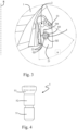
- the tool 100 for machining is designed as a milling tool, in particular as a high-speed milling cutter, which is designed for machining at a speed of up to several tens of thousands of revolutions per minute.
- the tool 100 has a base body 1, which can be made of a tool steel, tungsten heavy metal such as Densimet ® or a hard metal, for example.
- the base body 1 has a first end 11, which is provided with an interface for indirect or direct connection to a drive spindle of a processing machine (not shown), and a free end 12 facing away from the first end 11.
- the base body 1 has a rotation axis R, about which the tool 100 rotates during operation, i.e. during machining.
- a plurality of seats 2 for receiving replaceable cutting inserts 3 are provided in the area of the free end 12 in the base body 1.
- the seats 2 are arranged distributed over the circumference of the base body 1.
- a base body 1 is shown which has a total of four seats 2 for receiving replaceable cutting inserts 3, fewer such seats 2, but at least one, or more than four seats 2 can be provided.
- the seats 2 are arranged in such a way that a cutting insert 3 arranged in them projects axially with a secondary cutting edge 31 beyond the free end 12 of the base body 1 and projects radially with a main cutting edge 32 beyond the base body 1.
- the seats 2 are designed for a so-called radial clamping of the cutting inserts 3, in which the main extension plane of the on the respective seat 2 runs essentially radially and the longitudinal axis of the fastening screw 5, with which the cutting insert 3 is fastened to the seat, extends predominantly in the tangential direction. Since the seats 2 are essentially identical to one another and the cutting inserts 3 arranged on them are also at least essentially identical to one another, only one seat 2 and the fastening of a cutting insert 3 to it are explained in more detail below.
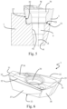
- the cutting insert 3 has a substantially polygonal basic shape with a bottom side 33 and an upper side 34 opposite the bottom side 33, which is designed as a chip surface, as shown in particular in Fig. 6 can be seen.
- the bottom 33 and the top 34 are connected to one another via side surfaces.
- a through hole 36 extends from the top 34 to the bottom 33 through the cutting insert 3.
- the secondary cutting edge 31 and the main cutting edge 32 are formed along the transition from the top 34 to the side surfaces and are connected to one another via a cutting corner 35.
- the cutting insert 3 has a two-fold rotational symmetry with respect to the longitudinal axis of the through hole 36, so that two cutting edge sections are provided, each of which has a main cutting edge 32 and a secondary cutting edge 31 connected to it via a cutting corner 35.
- Fig. 1 As can be seen, in the mounted state of the cutting insert 3 on the base body 1, one of the two cutting edge sections is in an active position in which the main cutting edge 32 protrudes radially beyond the base body 1 and the secondary cutting edge 31 protrudes axially beyond the base body 1, the other of the two cutting edge sections is in an inactive position.
- a cutting insert 3 is shown in which cutting edge sections are provided only at the transition from the upper side 34 to the side surfaces, in a modification a double-sided design of the cutting insert is also possible in which cutting edge sections are also provided at the transition from the lower side 33 to the side surfaces.
- the cutting insert 3 has a first side surface 37, with which the cutting insert 3 is supported radially inward on the seat 2.
- the first side surface 37 is formed on the side of the cutting insert 3 that is opposite the main cutting edge 32 in the active position. Due to the described two-fold rotational symmetry, there is also a further first side surface 37 below the main clearance surface of the active main cutting edge 32, which is assigned to the opposite inactive main cutting edge 32.
- the cutting insert 3 also has a second side surface 38, with which the cutting insert 3 is supported axially and radially outward on the seat 2.
- the second side surface 38 is formed on the side of the cutting insert 3 that is opposite the secondary cutting edge 31 in the active position. Due to the described two-fold rotational symmetry, there is also a further second side surface 38 on the side of the active secondary cutting edge 31, which is assigned to the opposite inactive secondary cutting edge 31.
- the seat 2 has a base surface 21 for supporting the underside 33 of the cutting insert 3, a first lateral contact surface 22 for supporting the first side surface 37 of the cutting insert 3 and a second lateral contact surface 23 for supporting the second side surface 38 of the cutting insert 3.
- a surface normal of the base surface 21 has a tangential directional component as its main component.
- the surface normal of the base surface 21 can also have smaller axial and/or radial directional components.
- the first lateral contact surface 22 supports the cutting insert 3 radially inward.
- the first lateral contact surface 22 can be formed as a continuous surface. However, it is possible It is also possible that the first lateral contact surface 22 has a plurality of separate partial surfaces for radially inward support, as is the case, for example, in Fig. 3 can be seen.
- the surface normal of the first lateral contact surface 22 has a directional component directed radially outwards as the main component.
- the surface normal of the first lateral contact surface 22 can, for example, only have a directional component directed radially outwards or can also have additional tangential and/or axial directional components of a smaller magnitude.
- the second lateral contact surface 23 supports the cutting insert 3 on its side facing away from the free end 12 of the base body 1 both in the axial direction and radially outward.
- the surface normal of the second lateral contact surface 23 has both an axial directional component in the direction of the free end 12 of the base body 1 and a radially inward directional component.
- the surface normal of the second lateral contact surface 23 can also have a small tangential directional component, as is the case, for example, with the Fig. 3 shown second lateral contact surface 23 is the case.
- the first lateral contact surface 22 and the second lateral contact surface 23 enclose an interior angle ⁇ with each other in a viewing direction perpendicular to the base surface 21, which is smaller than 75°, preferably smaller than 65°.
- the interior angle ⁇ is approximately 60°.
- the first lateral contact surface 22 encloses an interior angle ⁇ 90° with the base surface 21.
- the second lateral contact surface 23 encloses an interior angle ⁇ 90° with the base surface.
- the interior angle between the base surface 21 and the first lateral contact surface 22 is slightly larger than 90°, for example, can be approximately 100°.
- the interior angle between the base surface 21 and the second lateral contact surface 22 is slightly larger than 90° and can be approximately 100°, for example.
- the interior angles between the base surface 21 and the lateral contact surfaces 22, 23 can preferably each be 90°.
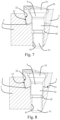
- a bore 4 is formed in the base surface 21 of the seat 2.
- the bore 4 extends from the base surface 21 into the material of the base body 1 and has, in an area spaced from the base surface 21, a threaded bore 41 with an internal thread for interacting with a corresponding external thread of the fastening screw 5, as will be described in more detail.
- a thread-free bore section 42 is formed between the threaded bore 41 and the opening of the bore 4 in the base surface 21.
- the thread-free bore section 42 has a circular cross-section and extends coaxially to the threaded bore 41.
- the thread-free bore section 42 it is also possible for the thread-free bore section 42 to have a different cross-sectional shape.
- the fastening screw 5 has a threaded portion 51 which is designed to cooperate with the threaded bore 41, a head portion 53 and a thread-free shaft portion 52 arranged between the head portion 53 and the threaded portion 51.
- a taper is provided between the threaded portion 51 and the thread-free shaft portion 52, which promotes a relative elastic deflection of the head portion 53 with respect to the threaded portion 51 in a direction perpendicular to a longitudinal axis of the fastening screw 5.
- the head portion 53 of the fastening screw 5 is designed to cooperate with the through hole 36 in the cutting insert 3.
- the head portion 53 has a largest cross-section which is larger than the smallest internal cross-section of the through hole 36, so that the head portion 53 cannot pass completely through the through hole 36.
- the head section 53 is adapted to the shape of the through hole 36 in such a way that the head section 53 can be supported on the through hole 36, in particular preferably in a ring shape.
- the thread-free shaft section 52 of the fastening screw 5 has a cross section that is significantly smaller than the cross section of the thread-free bore section 42 of the bore 4. In other words, the thread-free bore section 42 has an oversize all around compared to the thread-free shaft section 52, which is significantly larger than usual tolerances in a precise fit.
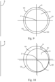
- the thread-free bore section 42 has four quadrants Q1, Q2, Q3 and Q4, which are numbered clockwise in the present case.
- a first quadrant Q1 of the thread-free bore section 42 is located on the side of the thread-free bore section 42 facing away from the free end 12 of the base body 1 and located radially outward.
- a second quadrant Q2 is located on the side of the free end 12 and radially outward.
- a third quadrant Q3 is also located on the side of the free end 12, but radially inward.
- a fourth quadrant Q4 is located on the side facing away from the free end 12 radially inward.
- the first quadrant Q1 is located between “12 o'clock and 3 o'clock” from a direction parallel to the rotation axis R
- the second quadrant Q2 is located between “3 o'clock and 6 o'clock”
- the third quadrant Q3 is located between “6 o'clock and 9 o'clock”
- the fourth quadrant Q4 is located between "9 o'clock and 12 o'clock”.
- the thread-free shaft section 52 in this state is spaced apart from the thread-free bore section 42 in the first quadrant Q1, as well as in the second quadrant Q2, in the third quadrant Q3 and in the fourth quadrant Q4.
- the longitudinal axis Z of the threaded bore 41 is spaced apart from the longitudinal axis W of the through hole 36 in the cutting insert 3 both in the direction of the first lateral contact surface 23 and in the direction the second lateral contact surface 23 slightly offset, as for example in Fig. 5 can be seen.
- an arrow P schematically shows (not to scale) the direction in which the longitudinal axis Z of the threaded hole 41 is displaced relative to the longitudinal axis W of the through hole 36.
- this direction is inclined at an angle ⁇ relative to the axial direction, so that the direction has a radially inward directional component and an axially rearward directional component, in the direction of the first end 11 of the base body 1.
- the angle ⁇ is, for example, between 50° and 70°.
- the threaded section 51 is screwed deeper into the threaded hole so that the head section 53 of the fastening screw 5 comes into contact with the through hole 36 of the cutting insert 3. Due to the described offset between the longitudinal axis W of the through hole 36 and the longitudinal axis Z of the threaded hole 41, the head section 53 first comes into contact in the area of the through hole 36 on the side between the first lateral contact surface 22 and the second lateral contact surface 23 of the seat 2. The cutting insert 3 is thereby pressed in the direction between the first lateral contact surface 22 and the second lateral contact surface 23.
- the resulting offset of the longitudinal axis Y of the fastening screw 5 in the area of the thread-free shaft section 52 relative to the longitudinal axis Z of the threaded bore 41 is shown schematically.
- the cutting insert 3 is secured in a form-fitting manner radially outward at a further position via the interaction of the thread-free shaft section 52 with the thread-free bore section 42, so that the cutting insert 3 is particularly reliable with respect to the machining
- the fastening screw 5 is secured against the centrifugal forces acting during machining.
- the shear forces caused by centrifugal forces on the fastening screw 5 do not act on the weaker thread section 51 of the fastening screw 5, but on the significantly more stable thread-free shaft section 52, which reduces the risk of material failure of the fastening screw 5.
- the head section 53 of the fastening screw 5 lies positively against the through hole 36. The interaction of the larger head section 53 of the fastening screw 5 with the smaller through hole 36 of the cutting insert 3 reliably braces the cutting insert 3 in the direction of the base surface 21 and secures the cutting insert 3 in a positive manner against lifting off the base surface 21.
- the thread-free shaft section 52 of the fastening screw 5 does not rest on the thread-free bore section 42 due to the oversize of the thread-free bore section 42 when the fastening screw 5 is tightened, as shown in particular in Fig. 10 can be seen.
- manufacturing tolerances of the cutting insert 3 as well as the first lateral contact surface 22 and the second lateral contact surface 23 can be easily compensated over a relatively large area.
- the cross-sectional shape of the thread-free bore section 42 is not limited to such a circular shape, but Other cross-sectional shapes are also possible, but the wall of the thread-free bore section 42 should preferably be concavely curved in the circumferential direction, at least in the second quadrant.
Landscapes
- Engineering & Computer Science (AREA)
- Mechanical Engineering (AREA)
- Milling Processes (AREA)
- Cutting Tools, Boring Holders, And Turrets (AREA)
Priority Applications (8)
| Application Number | Priority Date | Filing Date | Title |
|---|---|---|---|
| EP20216165.9A EP4015124B1 (de) | 2020-12-21 | 2020-12-21 | Werkzeug für die zerspanende bearbeitung |
| PL20216165.9T PL4015124T3 (pl) | 2020-12-21 | 2020-12-21 | Narzędzie do obróbki skrawaniem |
| ES20216165T ES3018624T3 (es) | 2020-12-21 | 2020-12-21 | Herramienta para mecanizado por arranque de virutas |
| KR1020237023633A KR102817368B1 (ko) | 2020-12-21 | 2021-12-07 | 절삭 가공을 위한 공구 및 그에 대한 절삭 인서트의 사용 |
| PCT/EP2021/084514 WO2022135899A1 (de) | 2020-12-21 | 2021-12-07 | Werkzeug für die zerspanende bearbeitung und verwendung eines schneideinsatzes an einem solchen |
| US18/258,613 US20240042533A1 (en) | 2020-12-21 | 2021-12-07 | Tool for cutting processing and use of a cutting insert thereon |
| CN202180083741.9A CN116600923B (zh) | 2020-12-21 | 2021-12-07 | 用于切削加工的工具及切削刀具在该工具上的使用 |
| JP2023536127A JP7682275B2 (ja) | 2020-12-21 | 2021-12-07 | 切削加工用工具、及び、その工具での切削インサートの使用 |
Applications Claiming Priority (1)
| Application Number | Priority Date | Filing Date | Title |
|---|---|---|---|
| EP20216165.9A EP4015124B1 (de) | 2020-12-21 | 2020-12-21 | Werkzeug für die zerspanende bearbeitung |
Publications (3)
| Publication Number | Publication Date |
|---|---|
| EP4015124A1 EP4015124A1 (de) | 2022-06-22 |
| EP4015124B1 true EP4015124B1 (de) | 2025-02-19 |
| EP4015124C0 EP4015124C0 (de) | 2025-02-19 |
Family
ID=74068226
Family Applications (1)
| Application Number | Title | Priority Date | Filing Date |
|---|---|---|---|
| EP20216165.9A Active EP4015124B1 (de) | 2020-12-21 | 2020-12-21 | Werkzeug für die zerspanende bearbeitung |
Country Status (8)
| Country | Link |
|---|---|
| US (1) | US20240042533A1 (pl) |
| EP (1) | EP4015124B1 (pl) |
| JP (1) | JP7682275B2 (pl) |
| KR (1) | KR102817368B1 (pl) |
| CN (1) | CN116600923B (pl) |
| ES (1) | ES3018624T3 (pl) |
| PL (1) | PL4015124T3 (pl) |
| WO (1) | WO2022135899A1 (pl) |
Families Citing this family (1)
| Publication number | Priority date | Publication date | Assignee | Title |
|---|---|---|---|---|
| CN120190396B (zh) * | 2025-05-06 | 2025-09-16 | 博锐拓沃精密工具(江苏)有限公司 | 一种金属切削刀具用微调机构 |
Family Cites Families (14)
| Publication number | Priority date | Publication date | Assignee | Title |
|---|---|---|---|---|
| BE793105A (fr) * | 1971-12-24 | 1973-04-16 | Walter Gmbh Montanwerke | Outil de fraisage a plaquettes de coupe echangeables |
| SE362369B (pl) * | 1973-02-21 | 1973-12-10 | Sandvik Ab | |
| CH578908A5 (pl) * | 1973-06-29 | 1976-08-31 | Walter Gmbh Montanwerke | |
| DE2906148A1 (de) * | 1979-02-17 | 1980-08-28 | Walter Gmbh Montanwerke | Schneidwerkzeug mit wendeplattenbestueckung |
| JPH03281115A (ja) * | 1990-03-30 | 1991-12-11 | Mitsubishi Materials Corp | スローアウエイ式切削工具 |
| KR100485852B1 (ko) * | 1996-04-19 | 2005-06-16 | 세코 툴스 에이비 | 칩제거용절삭공구및체결핀 |
| AT3955U1 (de) | 1999-09-09 | 2000-11-27 | Plansee Tizit Aktiengesellscha | Rotierendes zerspanungswerkzeug |
| SE523655C2 (sv) * | 2001-08-09 | 2004-05-04 | Sandvik Ab | Roterbart skärverktyg med ett skär som är fastspännbart med en partiellt böjlig spännskruv. |
| JP5076438B2 (ja) * | 2006-01-30 | 2012-11-21 | 三菱マテリアル株式会社 | インサート式切削工具及びインサート式切削工具におけるインサートの固定方法 |
| SE530698C2 (sv) * | 2006-12-21 | 2008-08-19 | Sandvik Intellectual Property | Svarvverktyg, samt grundkropp och underläggsplatta för dylika verktyg |
| SE531502C2 (sv) * | 2007-06-05 | 2009-04-28 | Sandvik Intellectual Property | Verktyg för spånavskiljande bearbetning samt grundkropp och indexerbart skär härför |
| AT11470U1 (de) * | 2009-06-10 | 2010-11-15 | Ceratizit Austria Gmbh | Schneidwerkzeug |
| AT14369U1 (de) * | 2014-11-24 | 2015-09-15 | Ceratizit Austria Gmbh | Werkzeug für die zerspanende Bearbeitung |
| CN106624100B (zh) * | 2016-12-19 | 2018-10-26 | 株洲钻石切削刀具股份有限公司 | 一种铣削刀具 |
-
2020
- 2020-12-21 ES ES20216165T patent/ES3018624T3/es active Active
- 2020-12-21 EP EP20216165.9A patent/EP4015124B1/de active Active
- 2020-12-21 PL PL20216165.9T patent/PL4015124T3/pl unknown
-
2021
- 2021-12-07 JP JP2023536127A patent/JP7682275B2/ja active Active
- 2021-12-07 WO PCT/EP2021/084514 patent/WO2022135899A1/de not_active Ceased
- 2021-12-07 CN CN202180083741.9A patent/CN116600923B/zh active Active
- 2021-12-07 KR KR1020237023633A patent/KR102817368B1/ko active Active
- 2021-12-07 US US18/258,613 patent/US20240042533A1/en active Pending
Also Published As
| Publication number | Publication date |
|---|---|
| ES3018624T3 (es) | 2025-05-16 |
| WO2022135899A1 (de) | 2022-06-30 |
| CN116600923B (zh) | 2025-10-28 |
| CN116600923A (zh) | 2023-08-15 |
| PL4015124T3 (pl) | 2025-06-09 |
| JP7682275B2 (ja) | 2025-05-23 |
| EP4015124C0 (de) | 2025-02-19 |
| US20240042533A1 (en) | 2024-02-08 |
| JP2023554040A (ja) | 2023-12-26 |
| EP4015124A1 (de) | 2022-06-22 |
| KR20230118652A (ko) | 2023-08-11 |
| KR102817368B1 (ko) | 2025-06-05 |
Similar Documents
| Publication | Publication Date | Title |
|---|---|---|
| EP2318166B1 (de) | Werkzeug für spanende bearbeitung eines werkstücks | |
| DE3831535A1 (de) | Stirnfraeser | |
| EP1993768A1 (de) | Schneideinsatz und fräswerkzeug | |
| EP3501701A1 (de) | Werkzeugsystem und verfahren zur drehbearbeitung | |
| WO2007090558A2 (de) | Kombinationswerkzeug und verfahren zur spanenden bearbeitung eines bohrlochs und dessen bohrungsoberfläche sowie schneidkörper für ein derartiges kombinationswerkzeug | |
| EP3996861B1 (de) | Doppelseitiger schneideinsatz zum fräsen | |
| AT14072U1 (de) | Doppelseitiger Frässchneideinsatz und Fräswerkzeug | |
| EP2081718A1 (de) | Schlicht- /schruppfräser | |
| EP3223983B1 (de) | Werkzeug für die zerspanende bearbeitung | |
| EP3071355B1 (de) | Kegelsenker | |
| EP3414038B1 (de) | Bohrwerkzeug | |
| EP4015124B1 (de) | Werkzeug für die zerspanende bearbeitung | |
| DE102007038935B4 (de) | Stabmesserkopf und entsprechende Werkzeugmaschine | |
| EP2212041A1 (de) | Werkzeugsystem, insbesondere zum nutstossen | |
| EP3463731B1 (de) | Schneidplatte für ein fräswerkzeug und fräswerkzeug | |
| DE102016104724B4 (de) | Wälzfräser | |
| WO2015017874A1 (de) | Trennfräser-schneideinsatz | |
| WO2003022496A1 (de) | Schneidplatte und fräswerkzeug mit einer derartigen schneidplatte | |
| EP1715975B1 (de) | Hochgeschwindigkeitsfräser | |
| EP3954482B1 (de) | Werkzeugsystem | |
| EP3888826A1 (de) | Zerspanungswerkzeug und verfahren zum indexieren eines schneideinsatzes | |
| EP2274127B1 (de) | Fräswerkzeug, insbesondere planfräser | |
| DE19602698C2 (de) | Werkzeug zur spanenden Feinbearbeitung von Bohrungsoberflächen | |
| DD280485A1 (de) | Schneideinsatz fuer kombinierte fraes- und anfaswerkzeuge | |
| EP4282564A1 (de) | Fräswerkzeug |
Legal Events
| Date | Code | Title | Description |
|---|---|---|---|
| PUAI | Public reference made under article 153(3) epc to a published international application that has entered the european phase |
Free format text: ORIGINAL CODE: 0009012 |
|
| STAA | Information on the status of an ep patent application or granted ep patent |
Free format text: STATUS: THE APPLICATION HAS BEEN PUBLISHED |
|
| AK | Designated contracting states |
Kind code of ref document: A1 Designated state(s): AL AT BE BG CH CY CZ DE DK EE ES FI FR GB GR HR HU IE IS IT LI LT LU LV MC MK MT NL NO PL PT RO RS SE SI SK SM TR |
|
| STAA | Information on the status of an ep patent application or granted ep patent |
Free format text: STATUS: REQUEST FOR EXAMINATION WAS MADE |
|
| 17P | Request for examination filed |
Effective date: 20221122 |
|
| RBV | Designated contracting states (corrected) |
Designated state(s): AL AT BE BG CH CY CZ DE DK EE ES FI FR GB GR HR HU IE IS IT LI LT LU LV MC MK MT NL NO PL PT RO RS SE SI SK SM TR |
|
| GRAP | Despatch of communication of intention to grant a patent |
Free format text: ORIGINAL CODE: EPIDOSNIGR1 |
|
| STAA | Information on the status of an ep patent application or granted ep patent |
Free format text: STATUS: GRANT OF PATENT IS INTENDED |
|
| INTG | Intention to grant announced |
Effective date: 20241127 |
|
| GRAS | Grant fee paid |
Free format text: ORIGINAL CODE: EPIDOSNIGR3 |
|
| GRAA | (expected) grant |
Free format text: ORIGINAL CODE: 0009210 |
|
| STAA | Information on the status of an ep patent application or granted ep patent |
Free format text: STATUS: THE PATENT HAS BEEN GRANTED |
|
| AK | Designated contracting states |
Kind code of ref document: B1 Designated state(s): AL AT BE BG CH CY CZ DE DK EE ES FI FR GB GR HR HU IE IS IT LI LT LU LV MC MK MT NL NO PL PT RO RS SE SI SK SM TR |
|
| REG | Reference to a national code |
Ref country code: GB Ref legal event code: FG4D Free format text: NOT ENGLISH |
|
| REG | Reference to a national code |
Ref country code: CH Ref legal event code: EP |
|
| REG | Reference to a national code |
Ref country code: DE Ref legal event code: R096 Ref document number: 502020010421 Country of ref document: DE |
|
| REG | Reference to a national code |
Ref country code: IE Ref legal event code: FG4D Free format text: LANGUAGE OF EP DOCUMENT: GERMAN |
|
| U01 | Request for unitary effect filed |
Effective date: 20250228 |
|
| U07 | Unitary effect registered |
Designated state(s): AT BE BG DE DK EE FI FR IT LT LU LV MT NL PT RO SE SI Effective date: 20250310 |
|
| REG | Reference to a national code |
Ref country code: ES Ref legal event code: FG2A Ref document number: 3018624 Country of ref document: ES Kind code of ref document: T3 Effective date: 20250516 |
|
| REG | Reference to a national code |
Ref country code: SK Ref legal event code: T3 Ref document number: E 46187 Country of ref document: SK |
|
| PG25 | Lapsed in a contracting state [announced via postgrant information from national office to epo] |
Ref country code: RS Free format text: LAPSE BECAUSE OF FAILURE TO SUBMIT A TRANSLATION OF THE DESCRIPTION OR TO PAY THE FEE WITHIN THE PRESCRIBED TIME-LIMIT Effective date: 20250519 |
|
| PG25 | Lapsed in a contracting state [announced via postgrant information from national office to epo] |
Ref country code: IS Free format text: LAPSE BECAUSE OF FAILURE TO SUBMIT A TRANSLATION OF THE DESCRIPTION OR TO PAY THE FEE WITHIN THE PRESCRIBED TIME-LIMIT Effective date: 20250619 Ref country code: NO Free format text: LAPSE BECAUSE OF FAILURE TO SUBMIT A TRANSLATION OF THE DESCRIPTION OR TO PAY THE FEE WITHIN THE PRESCRIBED TIME-LIMIT Effective date: 20250519 |
|
| PG25 | Lapsed in a contracting state [announced via postgrant information from national office to epo] |
Ref country code: HR Free format text: LAPSE BECAUSE OF FAILURE TO SUBMIT A TRANSLATION OF THE DESCRIPTION OR TO PAY THE FEE WITHIN THE PRESCRIBED TIME-LIMIT Effective date: 20250219 |
|
| PG25 | Lapsed in a contracting state [announced via postgrant information from national office to epo] |
Ref country code: GR Free format text: LAPSE BECAUSE OF FAILURE TO SUBMIT A TRANSLATION OF THE DESCRIPTION OR TO PAY THE FEE WITHIN THE PRESCRIBED TIME-LIMIT Effective date: 20250520 |
|
| PG25 | Lapsed in a contracting state [announced via postgrant information from national office to epo] |
Ref country code: SM Free format text: LAPSE BECAUSE OF FAILURE TO SUBMIT A TRANSLATION OF THE DESCRIPTION OR TO PAY THE FEE WITHIN THE PRESCRIBED TIME-LIMIT Effective date: 20250219 |
|
| PLBE | No opposition filed within time limit |
Free format text: ORIGINAL CODE: 0009261 |
|
| STAA | Information on the status of an ep patent application or granted ep patent |
Free format text: STATUS: NO OPPOSITION FILED WITHIN TIME LIMIT |
|
| REG | Reference to a national code |
Ref country code: CH Ref legal event code: L10 Free format text: ST27 STATUS EVENT CODE: U-0-0-L10-L00 (AS PROVIDED BY THE NATIONAL OFFICE) Effective date: 20251231 |
|
| REG | Reference to a national code |
Ref country code: CH Ref legal event code: U11 Free format text: ST27 STATUS EVENT CODE: U-0-0-U10-U11 (AS PROVIDED BY THE NATIONAL OFFICE) Effective date: 20260101 |
|
| PGFP | Annual fee paid to national office [announced via postgrant information from national office to epo] |
Ref country code: GB Payment date: 20251219 Year of fee payment: 6 |
|
| PGFP | Annual fee paid to national office [announced via postgrant information from national office to epo] |
Ref country code: TR Payment date: 20251216 Year of fee payment: 6 |
|
| PGFP | Annual fee paid to national office [announced via postgrant information from national office to epo] |
Ref country code: CZ Payment date: 20251218 Year of fee payment: 6 |
|
| PGFP | Annual fee paid to national office [announced via postgrant information from national office to epo] |
Ref country code: PL Payment date: 20251212 Year of fee payment: 6 |
|
| PGFP | Annual fee paid to national office [announced via postgrant information from national office to epo] |
Ref country code: SK Payment date: 20251218 Year of fee payment: 6 |
|
| 26N | No opposition filed |
Effective date: 20251120 |
|
| U20 | Renewal fee for the european patent with unitary effect paid |
Year of fee payment: 6 Effective date: 20251230 |
|
| PGFP | Annual fee paid to national office [announced via postgrant information from national office to epo] |
Ref country code: ES Payment date: 20260130 Year of fee payment: 6 |