EP4015026B1 - Bidirektionales strömungssteuerbares künstliches beatmungsgerät - Google Patents
Bidirektionales strömungssteuerbares künstliches beatmungsgerät Download PDFInfo
- Publication number
- EP4015026B1 EP4015026B1 EP20854741.4A EP20854741A EP4015026B1 EP 4015026 B1 EP4015026 B1 EP 4015026B1 EP 20854741 A EP20854741 A EP 20854741A EP 4015026 B1 EP4015026 B1 EP 4015026B1
- Authority
- EP
- European Patent Office
- Prior art keywords
- air
- opening
- supply
- flow
- control
- Prior art date
- Legal status (The legal status is an assumption and is not a legal conclusion. Google has not performed a legal analysis and makes no representation as to the accuracy of the status listed.)
- Active
Links
Images



Classifications
-
- A—HUMAN NECESSITIES
- A61—MEDICAL OR VETERINARY SCIENCE; HYGIENE
- A61M—DEVICES FOR INTRODUCING MEDIA INTO, OR ONTO, THE BODY; DEVICES FOR TRANSDUCING BODY MEDIA OR FOR TAKING MEDIA FROM THE BODY; DEVICES FOR PRODUCING OR ENDING SLEEP OR STUPOR
- A61M16/00—Devices for influencing the respiratory system of patients by gas treatment, e.g. ventilators; Tracheal tubes
- A61M16/20—Valves specially adapted to medical respiratory devices
-
- A—HUMAN NECESSITIES
- A61—MEDICAL OR VETERINARY SCIENCE; HYGIENE
- A61M—DEVICES FOR INTRODUCING MEDIA INTO, OR ONTO, THE BODY; DEVICES FOR TRANSDUCING BODY MEDIA OR FOR TAKING MEDIA FROM THE BODY; DEVICES FOR PRODUCING OR ENDING SLEEP OR STUPOR
- A61M16/00—Devices for influencing the respiratory system of patients by gas treatment, e.g. ventilators; Tracheal tubes
- A61M16/021—Devices for influencing the respiratory system of patients by gas treatment, e.g. ventilators; Tracheal tubes operated by electrical means
- A61M16/022—Control means therefor
- A61M16/024—Control means therefor including calculation means, e.g. using a processor
-
- A—HUMAN NECESSITIES
- A61—MEDICAL OR VETERINARY SCIENCE; HYGIENE
- A61M—DEVICES FOR INTRODUCING MEDIA INTO, OR ONTO, THE BODY; DEVICES FOR TRANSDUCING BODY MEDIA OR FOR TAKING MEDIA FROM THE BODY; DEVICES FOR PRODUCING OR ENDING SLEEP OR STUPOR
- A61M16/00—Devices for influencing the respiratory system of patients by gas treatment, e.g. ventilators; Tracheal tubes
- A61M16/0057—Pumps therefor
- A61M16/0066—Blowers or centrifugal pumps
- A61M16/0069—Blowers or centrifugal pumps the speed thereof being controlled by respiratory parameters, e.g. by inhalation
-
- A—HUMAN NECESSITIES
- A61—MEDICAL OR VETERINARY SCIENCE; HYGIENE
- A61M—DEVICES FOR INTRODUCING MEDIA INTO, OR ONTO, THE BODY; DEVICES FOR TRANSDUCING BODY MEDIA OR FOR TAKING MEDIA FROM THE BODY; DEVICES FOR PRODUCING OR ENDING SLEEP OR STUPOR
- A61M16/00—Devices for influencing the respiratory system of patients by gas treatment, e.g. ventilators; Tracheal tubes
- A61M16/20—Valves specially adapted to medical respiratory devices
- A61M16/201—Controlled valves
- A61M16/202—Controlled valves electrically actuated
-
- A—HUMAN NECESSITIES
- A61—MEDICAL OR VETERINARY SCIENCE; HYGIENE
- A61M—DEVICES FOR INTRODUCING MEDIA INTO, OR ONTO, THE BODY; DEVICES FOR TRANSDUCING BODY MEDIA OR FOR TAKING MEDIA FROM THE BODY; DEVICES FOR PRODUCING OR ENDING SLEEP OR STUPOR
- A61M16/00—Devices for influencing the respiratory system of patients by gas treatment, e.g. ventilators; Tracheal tubes
- A61M16/20—Valves specially adapted to medical respiratory devices
- A61M16/208—Non-controlled one-way valves, e.g. exhalation, check, pop-off non-rebreathing valves
-
- A—HUMAN NECESSITIES
- A62—LIFE-SAVING; FIRE-FIGHTING
- A62B—DEVICES, APPARATUS OR METHODS FOR LIFE-SAVING
- A62B18/00—Breathing masks or helmets, e.g. affording protection against chemical agents or for use at high altitudes or incorporating a pump or compressor for reducing the inhalation effort
- A62B18/08—Component parts for gas-masks or gas-helmets, e.g. windows, straps, speech transmitters, signal-devices
- A62B18/10—Valves
-
- G—PHYSICS
- G09—EDUCATION; CRYPTOGRAPHY; DISPLAY; ADVERTISING; SEALS
- G09B—EDUCATIONAL OR DEMONSTRATION APPLIANCES; APPLIANCES FOR TEACHING, OR COMMUNICATING WITH, THE BLIND, DEAF OR MUTE; MODELS; PLANETARIA; GLOBES; MAPS; DIAGRAMS
- G09B23/00—Models for scientific, medical, or mathematical purposes, e.g. full-sized devices for demonstration purposes
- G09B23/28—Models for scientific, medical, or mathematical purposes, e.g. full-sized devices for demonstration purposes for medicine
- G09B23/288—Models for scientific, medical, or mathematical purposes, e.g. full-sized devices for demonstration purposes for medicine for artificial respiration or heart massage
-
- A—HUMAN NECESSITIES
- A61—MEDICAL OR VETERINARY SCIENCE; HYGIENE
- A61M—DEVICES FOR INTRODUCING MEDIA INTO, OR ONTO, THE BODY; DEVICES FOR TRANSDUCING BODY MEDIA OR FOR TAKING MEDIA FROM THE BODY; DEVICES FOR PRODUCING OR ENDING SLEEP OR STUPOR
- A61M16/00—Devices for influencing the respiratory system of patients by gas treatment, e.g. ventilators; Tracheal tubes
- A61M16/0057—Pumps therefor
- A61M16/0084—Pumps therefor self-reinflatable by elasticity, e.g. resuscitation squeeze bags
-
- A—HUMAN NECESSITIES
- A61—MEDICAL OR VETERINARY SCIENCE; HYGIENE
- A61M—DEVICES FOR INTRODUCING MEDIA INTO, OR ONTO, THE BODY; DEVICES FOR TRANSDUCING BODY MEDIA OR FOR TAKING MEDIA FROM THE BODY; DEVICES FOR PRODUCING OR ENDING SLEEP OR STUPOR
- A61M16/00—Devices for influencing the respiratory system of patients by gas treatment, e.g. ventilators; Tracheal tubes
- A61M16/06—Respiratory or anaesthetic masks
-
- A—HUMAN NECESSITIES
- A61—MEDICAL OR VETERINARY SCIENCE; HYGIENE
- A61M—DEVICES FOR INTRODUCING MEDIA INTO, OR ONTO, THE BODY; DEVICES FOR TRANSDUCING BODY MEDIA OR FOR TAKING MEDIA FROM THE BODY; DEVICES FOR PRODUCING OR ENDING SLEEP OR STUPOR
- A61M16/00—Devices for influencing the respiratory system of patients by gas treatment, e.g. ventilators; Tracheal tubes
- A61M16/08—Bellows; Connecting tubes ; Water traps; Patient circuits
- A61M16/0816—Joints or connectors
- A61M16/0833—T- or Y-type connectors, e.g. Y-piece
-
- A—HUMAN NECESSITIES
- A61—MEDICAL OR VETERINARY SCIENCE; HYGIENE
- A61M—DEVICES FOR INTRODUCING MEDIA INTO, OR ONTO, THE BODY; DEVICES FOR TRANSDUCING BODY MEDIA OR FOR TAKING MEDIA FROM THE BODY; DEVICES FOR PRODUCING OR ENDING SLEEP OR STUPOR
- A61M16/00—Devices for influencing the respiratory system of patients by gas treatment, e.g. ventilators; Tracheal tubes
- A61M16/20—Valves specially adapted to medical respiratory devices
- A61M16/201—Controlled valves
- A61M16/202—Controlled valves electrically actuated
- A61M16/203—Proportional
- A61M16/204—Proportional used for inhalation control
-
- A—HUMAN NECESSITIES
- A61—MEDICAL OR VETERINARY SCIENCE; HYGIENE
- A61M—DEVICES FOR INTRODUCING MEDIA INTO, OR ONTO, THE BODY; DEVICES FOR TRANSDUCING BODY MEDIA OR FOR TAKING MEDIA FROM THE BODY; DEVICES FOR PRODUCING OR ENDING SLEEP OR STUPOR
- A61M16/00—Devices for influencing the respiratory system of patients by gas treatment, e.g. ventilators; Tracheal tubes
- A61M16/20—Valves specially adapted to medical respiratory devices
- A61M16/201—Controlled valves
- A61M16/202—Controlled valves electrically actuated
- A61M16/203—Proportional
- A61M16/205—Proportional used for exhalation control
-
- A—HUMAN NECESSITIES
- A61—MEDICAL OR VETERINARY SCIENCE; HYGIENE
- A61M—DEVICES FOR INTRODUCING MEDIA INTO, OR ONTO, THE BODY; DEVICES FOR TRANSDUCING BODY MEDIA OR FOR TAKING MEDIA FROM THE BODY; DEVICES FOR PRODUCING OR ENDING SLEEP OR STUPOR
- A61M16/00—Devices for influencing the respiratory system of patients by gas treatment, e.g. ventilators; Tracheal tubes
- A61M16/20—Valves specially adapted to medical respiratory devices
- A61M16/208—Non-controlled one-way valves, e.g. exhalation, check, pop-off non-rebreathing valves
- A61M16/209—Relief valves
-
- A—HUMAN NECESSITIES
- A61—MEDICAL OR VETERINARY SCIENCE; HYGIENE
- A61M—DEVICES FOR INTRODUCING MEDIA INTO, OR ONTO, THE BODY; DEVICES FOR TRANSDUCING BODY MEDIA OR FOR TAKING MEDIA FROM THE BODY; DEVICES FOR PRODUCING OR ENDING SLEEP OR STUPOR
- A61M16/00—Devices for influencing the respiratory system of patients by gas treatment, e.g. ventilators; Tracheal tubes
- A61M16/0003—Accessories therefor, e.g. sensors, vibrators, negative pressure
- A61M2016/0027—Accessories therefor, e.g. sensors, vibrators, negative pressure pressure meter
-
- A—HUMAN NECESSITIES
- A61—MEDICAL OR VETERINARY SCIENCE; HYGIENE
- A61M—DEVICES FOR INTRODUCING MEDIA INTO, OR ONTO, THE BODY; DEVICES FOR TRANSDUCING BODY MEDIA OR FOR TAKING MEDIA FROM THE BODY; DEVICES FOR PRODUCING OR ENDING SLEEP OR STUPOR
- A61M16/00—Devices for influencing the respiratory system of patients by gas treatment, e.g. ventilators; Tracheal tubes
- A61M16/0003—Accessories therefor, e.g. sensors, vibrators, negative pressure
- A61M2016/003—Accessories therefor, e.g. sensors, vibrators, negative pressure with a flowmeter
- A61M2016/0033—Accessories therefor, e.g. sensors, vibrators, negative pressure with a flowmeter electrical
-
- A—HUMAN NECESSITIES
- A61—MEDICAL OR VETERINARY SCIENCE; HYGIENE
- A61M—DEVICES FOR INTRODUCING MEDIA INTO, OR ONTO, THE BODY; DEVICES FOR TRANSDUCING BODY MEDIA OR FOR TAKING MEDIA FROM THE BODY; DEVICES FOR PRODUCING OR ENDING SLEEP OR STUPOR
- A61M16/00—Devices for influencing the respiratory system of patients by gas treatment, e.g. ventilators; Tracheal tubes
- A61M16/0003—Accessories therefor, e.g. sensors, vibrators, negative pressure
- A61M2016/003—Accessories therefor, e.g. sensors, vibrators, negative pressure with a flowmeter
- A61M2016/0033—Accessories therefor, e.g. sensors, vibrators, negative pressure with a flowmeter electrical
- A61M2016/0039—Accessories therefor, e.g. sensors, vibrators, negative pressure with a flowmeter electrical in the inspiratory circuit
Definitions
- Disclosed is a bidirectional flow-controllable artificial respirator.
- Cardiopulmonary resuscitation is performed to a patient, who cannot spontaneously breathe, to supply oxygen to the patient and maintain the patient's blood flow.
- an air mask bag unit is generally used to induce breathing.
- the AMBU refers to a manual artificial respiration device to supply air by applying positive pressure to the lungs by using an airbag in a state in which a mask covers the nose and the mouth.
- the chest compression is temporarily stopped at the time of supplying air.
- the chest compression is performed again after sufficiently supplying air into the lungs. This process is repeated to induce the patient's breathing.
- cardiopulmonary resuscitation including the artificial respiration method is to maintain a minimum blood flow toward a cerebral blood vessel while chest compression and relaxation are repeated, to maintain a blood flow toward the coronary artery during chest relaxation, and to appropriately supply oxygen.
- Korean Patent Application Publication No. 10-2018-0041535 filed on October 14, 2018 discloses "Flow Control Manual Artificial Respiration Device Via Feedback and Method of Injecting Artificial Respiration Using the Same".
- US 2009/0266364 A1 discloses a ventilation device and method to be used on a patient during cardiopulmonary resuscitation.
- the ventilation device comprises a housing having at least one opening for interfacing with a patient's airway, at least one valve configured to permit outflow of respiratory gases/air from the airway to ambient, a release mechanism for opening and closing an inlet passage to permit inflow of respiratory gases/air to the airway, and a control device for controlling the opening/closing of the inlet passage.
- US 2002/0069878 A1 discloses methods and devices for increasing cardiopulmonary circulation induced by chest compression and decompression when performing cardiopulmonary resuscitation are provided.
- a pressure responsive inflow valve is coupled to a patient's airway. Chest compressions and chest decompressions are performed. During chest decompression the inflow valve prevents respiratory gases from entering the lungs until a certain negative intrathoracic pressure level is exceeded at which time the one inflow valve opens. In this way, the inflow valve assists in increasing the magnitude and duration of negative intrathoracic pressure during decompression to enhance the amount of blood flow into the heart and lungs. Further, the patient is supplied with a pressurized respiratory gas through the inflow valve when the inflow valve opens to ventilate the patient.
- WO 2008/130937 A2 discloses a method for regulating gas flows into and out of a patient in which respiratory gases are repeatedly forced out of the lungs. Respiratory gases are prevented from entering back into the lungs during a time between when respiratory gases are forced out of the lungs. Periodically, an oxygen-containing gas is supplied to the lungs.
- An object of the embodiment is to provide an artificial respirator capable of selectively cutting off a supply of air into the lungs while chest compression is performed during artificial respiration.
- Another object of the embodiment is to provide an artificial respirator capable of selectively allowing a supply of air into the lungs while chest relaxation is performed during artificial respiration.
- Still another object of the embodiment is to provide an artificial respirator capable of allowing an appropriate amount of air to be naturally supplied by negative pressure in the lungs during artificial respiration.
- Yet another object of the embodiment is to provide an artificial respirator capable of consistently supplying air while chest compression and relaxation are repeated.
- Still yet another object of the embodiment is to provide an artificial respirator capable of maintaining negative pressure in the lungs for a long period after ventilation.
- a further object of the embodiment is to provide an artificial respirator capable of maintaining an appropriate blood flow rate to the cerebral blood vessel and the coronary artery.
- a bidirectional flow-controllable artificial respirator according to the invention is defined in the claims.
- the first control part may include a first rotary plate to open or close the first transmission part
- the second control part may include a second rotary plate to open or close the second transmission part
- the first and second rotary plates may be disposed to be orthogonal to each other and rotate together by means of a rotary shaft to connect the first and second rotary plates.
- the bidirectional flow-controllable artificial respirator it is possible to selectively allow a supply of air into the lungs while chest relaxation is performed during artificial respiration.
- the bidirectional flow-controllable artificial respirator it is possible to allow an appropriate amount of air to be naturally supplied by negative pressure in the lungs during artificial respiration.
- the bidirectional flow-controllable artificial respirator according to the embodiment, it is possible to consistently supply air while chest compression and relaxation are repeated.
- the bidirectional flow-controllable artificial respirator it is possible to maintain negative pressure in the lungs for a long period after ventilation.
- first, second, A, B, (a), and (b) may be used to describe constituent elements of the embodiments. These terms are used only for the purpose of discriminating one constituent element from another constituent element, and the nature, the sequences, or the orders of the constituent elements are not limited by the terms.
- one constituent element is described as being “connected”, “coupled”, or “attached” to another constituent element, it should be understood that one constituent element can be connected or attached directly to another constituent element, and an intervening constituent element can also be “connected”, “coupled”, or “attached” to the constituent elements.
- the constituent element which has the same common function as the constituent element included in any one embodiment, will be described by using the same name in other embodiments. Unless disclosed to the contrary, the configuration disclosed in any one embodiment may be applied to other embodiments, and the specific description of the repeated configuration will be omitted.
- the airbag is automatically filled with air and may supply air to be injected into the lungs.
- the mask may be connected to the valve and worn around the patient's mouth.
- a user of the artificial respirator may adjust the amount of air to be supplied to the patient by adjusting a degree to which the user presses the airbag and a speed at which the user presses the airbag.
- an oxygen tank or the like may be coupled to the airbag by connecting a line.
- FIG. 1 is a view schematically illustrating an artificial respirator 1 having a flow control valve unit 10 according to an embodiment of the invention.
- the artificial respirator 1 may be used to supply air to a subject receiving air that needs to receive air.
- the artificial respirator 1 may be connected to an air supply source disposed outside the artificial respirator 1.
- the subject receiving air may be a patient's lungs
- the air supply source may be an oxygen tank or outside air.
- the chamber C may store air introduced from the air supply source, and the stored air may be supplied into the lungs at the time of supplying air.
- the tube T is a tube connected to the air supply source to allow the air supply source to communicate with the lungs L or allow the chamber C to communicate with the patient's lungs L. Therefore, the air flows into the lungs L from the outside or flows to the outside from the lungs L through the tube T.
- the flow control valve unit 10 may be a combination of two check valves each to allow a flow only in one direction.
- each of the check valves constituting the flow control valve unit 10 may be provided as a swing check valve.
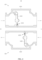
- the flow control valve unit 10 will be described below in more detail with reference to FIGS. 2 to 4 .
- the chamber valve V may be installed at one side of the chamber C to control the amount of air in the chamber C.
- the chamber valve V is maintained in a closed state at normal times. However, when the supply of air is continuously performed and both the lungs L and the chamber C are fully filled with air, the chamber valve V is opened to discharge a part of the air.
- the artificial respirator 1 according to the embodiment further includes a first sensor (not illustrated) and a second sensor (not illustrated).
- the first sensor may be provided in the tube T and disposed at a position adjacent to the flow control valve unit 10.
- the first sensor may measure a flow velocity of the air passing through the flow control valve unit 10.
- the first sensor may be provided as a flow sensor.
- the second sensor may be provided in the tube T and disposed to be closer to the respiratory tract than is the first sensor.
- the second sensor may measure a pressure applied in the respiratory tract.
- the second sensor may be provided as a pressure sensor.
- the electronic system including the first and second sensors may control the flow of air in the flow control valve unit 10 of the artificial respirator 1.
- the electronic system may control the flow control valve unit 10 so that the flow control valve unit 10 induces a flow of intake air by being synchronized with the chest relaxation in a 10-second cycle while the chest compression and relaxation are repeated.
- the flow control valve unit 10 may be controlled to induce the flow of intake air at the chest relaxation timing. Then, when the pressure in the respiratory tract becomes higher than a reference pressure by the flow of intake air, the flow control valve unit 10 may be controlled to return the state back to the original state.
- a mechanical valve opening/closing device may be applied, which manually opens or closes the valve at the chest relaxation timing after the chest compression and relaxation are repeated ten times, for example.
- FIG. 2 is a schematic longitudinal sectional view of the flow control valve unit 10 according to Embodiment 1, according to the present invention.
- the flow control valve unit 10 includes a first valve 101 and a second valve 102.
- the first and second valves 101 and 102 may each be provided as the same check valve.
- the first and second valves 101 and 102 may constitute the flow control valve unit 10 by being coupled to be disposed in opposite directions.
- first and second valves 101 and 102 may each be provided as a one-way valve that allows a flow from one side to the other side of the valve but does not allow the reverse flow.
- first and second valves 101 and 102 may each be a swing check valve.
- the first valve 101 allows an air supply path from an air supply source O to the inside of the lungs L.
- the first valve 101 includes a first transmission part 1011, a first opening/closing part 1012, and a first control part 1013.
- the first transmission part 1011 may define a body of the first valve 101 and have openings formed at two opposite sides thereof.
- the air may be introduced into the first transmission part 1011 from the air supply source O through one opening and discharged through the other opening.
- the air may pass through the first transmission part 1011 so as to be supplied into the lungs L.
- the first opening/closing part 1012 is disposed in the first transmission part 1011 and may include a disc, a hinge, a seat, and the like.
- the disc serves to substantially block or allow a flow path of a fluid.
- the hinge may be fixed to the transmission part 1011 and connected to one side of the disc so that the disc may rotate about the hinge, as a rotation center, when the disc allows the flow in one direction or blocks the flow in the other direction.
- the seat may be fixed to the transmission part 1011 and support the disc at the other side of the disc so that the disc blocks the flow in the other direction.
- the first opening/closing part 1012 configured as described above may rotate so that the air may flow only into the lungs L from the air supply source O. That is, the first opening/closing part 1012 may be autonomously opened when the flow rate of the air is equal to or higher than a predetermined flow rate when the air flows from the air supply source O to the lungs L. On the contrary, when the air flows in the direction in which the air is discharged from the lungs L, the first opening/closing part 1012 may be maintained in the closed state by being caught by a support part disposed in the first transmission part 1011.
- the first control part 1013 is disposed in the first transmission part 1011 and spaced apart from the first opening/closing part 1012.
- the first control part 1013 may be manually or automatically opened or closed and control the flow of air through the first opening/closing part 1012. That is, the first control part 1013 may be closed to block the air supply path so that the air is not supplied into the lungs L even though the flow from the air supply source O toward the lungs L is generated.
- the second valve 102 allows an air discharge path from the inside of the lungs L to the outside O of the artificial respirator.
- the second valve 102 includes a second transmission part 1021, a second opening/closing part 1022, and a second control part 1023.
Landscapes
- Health & Medical Sciences (AREA)
- Engineering & Computer Science (AREA)
- Pulmonology (AREA)
- General Health & Medical Sciences (AREA)
- Heart & Thoracic Surgery (AREA)
- Veterinary Medicine (AREA)
- Emergency Medicine (AREA)
- Anesthesiology (AREA)
- Biomedical Technology (AREA)
- Hematology (AREA)
- Life Sciences & Earth Sciences (AREA)
- Animal Behavior & Ethology (AREA)
- Public Health (AREA)
- Business, Economics & Management (AREA)
- General Physics & Mathematics (AREA)
- Physics & Mathematics (AREA)
- Emergency Management (AREA)
- Medicinal Chemistry (AREA)
- Mathematical Optimization (AREA)
- Chemical & Material Sciences (AREA)
- Algebra (AREA)
- Computational Mathematics (AREA)
- Cardiology (AREA)
- Mathematical Analysis (AREA)
- Medical Informatics (AREA)
- Mathematical Physics (AREA)
- Pure & Applied Mathematics (AREA)
- Educational Administration (AREA)
- Educational Technology (AREA)
- Theoretical Computer Science (AREA)
- Respiratory Apparatuses And Protective Means (AREA)
Claims (2)
- Bidirektionales strömungssteuerbares künstliches Beatmungsgerät (1), umfassend:eine Kammer (C) zum Speichern von Luft;einen Schlauch (T), der mit der Kammer (C) so verbunden ist, dass die Luft darin strömt;eine Maske, die mit dem Schlauch (T) verbunden ist, um um ein Gesicht oder eine Mundhöhle herum angebracht zu werden;eine in dem Schlauch (T) angeordnete Strömungssteuerventileinheit (10) zum Steuern eines Luftstroms zwischen der Maske und der Kammer (C) oder einer Luftversorgungsquelle (O); undeinen Messsensor, der in dem Schlauch (T) angeordnet ist, um eine Strömungsgeschwindigkeit der Luft, die durch die Strömungssteuerventileinheit (10) strömt, oder einen Druck zu messen, der auf einen Atmungstrakt wirkt,wobei die Strömungssteuerventileinheit (10) umfasst:ein erstes Ventil (101), um einen Luftzufuhrweg von der Luftzufuhrquelle (O) zu der Maske zu ermöglichen; undein zweites Ventil (102), um einen Luftablassweg von der Maske zu der Außenseite des künstlichen Beatmungsgeräts (1) zu ermöglichen,wobei das erste und das zweite Ventil (101, 102) so angepasst sind, dass sie während der künstlichen Beatmung abwechselnd geöffnet oder geschlossen werden,wobei das erste Ventil (101) so angepasst ist, dass es während der Brustkompression geschlossen wird, so dass der Unterdruck in einem Patienten, der Luft erhält, über einen langen Zeitraum aufrechterhalten wird, undwobei das erste und das zweite Ventil (101, 102) so angepasst sind, dass sie selektiv geöffnet oder geschlossen werden können, um eine Luftzufuhr gemäß einer voreingestellten Luftzufuhrperiode zu ermöglichen,wobei das erste Ventil (101) umfasst:ein erstes Übertragungsteil (1011), durch das die Luft strömt, wenn die Luft von der Luftzufuhrquelle (O) in Richtung der Maske geleitet wird;ein erstes Öffnungs-/Schließteil (1012), das in dem ersten Übertragungsteil (1011) angeordnet ist, um eine Strömung nur in einer Richtung von der Luftzufuhrquelle (O) zu der Maske zu ermöglichen; undein erstes Steuerteil (1013), das im ersten Übertragungsteil (1011) angeordnet und von dem ersten Öffnungs-/Schließteil (1012) beabstandet ist, undwobei die Luftzufuhr während der Kompression des Brustkorbs unterbrochen wird und, wenn der von dem Messsensor gemessene Druck während der Entspannung des Brustkorbs einen voreingestellten Druck erreicht, das erste Steuerteil (1013) so angepasst ist, dass es die Luftzufuhr durch das erste Öffnungs-/Schließteil (1012) selektiv steuert, so dass die Luftzufuhr entsprechend der voreingestellten Luftzufuhrperiode zugelassen wird,wobei das zweite Ventil (102) umfasst:ein zweites Übertragungsteil (1021), durch das die Luft strömt, wenn die Luft von der Maske nach außen abgegeben wird;ein zweites Öffnungs-/Schließteil (1022), das in dem zweiten Übertragungsteil (1021) angeordnet ist, um eine Strömung nur in einer Richtung von der Maske nach außen zu ermöglichen; undein zweites Steuerteil (1023), das in dem zweiten Übertragungsteil (1021) angeordnet und von dem zweiten Öffnungs-/Schließteil (1022) beabstandet ist, undwobei das zweite Steuerteil (1023) dazu angepasst ist, eine Abgabe von Luft durch das zweite Öffnungs-/Schließteil (1022) selektiv zu steuern, so dass die Abgabe von Luft während der Brustkorbkompression zugelassen wird und die Abgabe von Luft gemäß der voreingestellten Luftzufuhrperiode unterbrochen wird,dadurch gekennzeichnet, dassdas erste Steuerteil (1013) eine erste Drehplatte umfasst, um das erste Übertragungsteil (1011) zu öffnen oder zu schließen, das zweite Steuerteil (1023) eine zweite Drehplatte umfasst, um das zweite Übertragungsteil (1021) zu öffnen oder zu schließen, und die erste und die zweite Drehplatte so angeordnet sind, dass sie orthogonal zueinander sind und sich zusammen mittels einer Drehwelle drehen, um die erste und die zweite Drehplatte zu verbinden.
- Bidirektionales strömungssteuerbares künstliches Beatmungsgerät (1) nach Anspruch 1, wobei das erste Steuerteil (1013) so angepasst ist, dass es während der Brustkorbkompression geschlossen wird, um die Luftzufuhr durch das erste Öffnungs-/Schließteil (1012) zu unterbrechen,wobei das erste Steuerteil (1013) so angepasst ist, dass es zu einem voreingestellten Zeitpunkt der Luftzufuhr geöffnet wird, um die Luftzufuhr durch das erste Öffnungs-/Schließteil (1012) zu ermöglichen,wobei das erste Steuerteil (1013) so angepasst ist, dass es geschlossen wird, um einen Unterdruck in dem Luft empfangenden Subjekt über einen langen Zeitraum aufrechtzuerhalten, wenn ein Zeitpunkt nicht der Zeitpunkt der Luftzufuhr ist,wobei das zweite Steuerteil (1023) so angepasst ist, dass es während der Brustkorbkompression geöffnet wird, um die Abgabe von Luft durch das zweite Öffnungs-/Schließteil (1022) zu ermöglichen,wobei das zweite Steuerteil (1023) so angepasst ist, dass es zu dem voreingestellten Zeitpunkt der Luftzufuhr geschlossen wird, um die Abgabe von Luft durch das zweite Öffnungs-/Schließteil (1022) zu unterbrechen, undwobei das zweite Steuerteil (1023) so angepasst ist, dass es geöffnet wird, um die Effizienz der Luftzufuhr zu verbessern, wenn ein Zeitpunkt nicht der Zeitpunkt der Luftzufuhr ist.
Applications Claiming Priority (3)
| Application Number | Priority Date | Filing Date | Title |
|---|---|---|---|
| KR20190100334 | 2019-08-16 | ||
| KR1020200100359A KR102470057B1 (ko) | 2019-08-16 | 2020-08-11 | 양방향 흐름 제어 인공호흡장치 |
| PCT/KR2020/095107 WO2021034172A1 (ko) | 2019-08-16 | 2020-08-14 | 양방향 흐름 제어 인공호흡장치 |
Publications (3)
| Publication Number | Publication Date |
|---|---|
| EP4015026A1 EP4015026A1 (de) | 2022-06-22 |
| EP4015026A4 EP4015026A4 (de) | 2023-08-23 |
| EP4015026B1 true EP4015026B1 (de) | 2025-01-01 |
Family
ID=74660025
Family Applications (1)
| Application Number | Title | Priority Date | Filing Date |
|---|---|---|---|
| EP20854741.4A Active EP4015026B1 (de) | 2019-08-16 | 2020-08-14 | Bidirektionales strömungssteuerbares künstliches beatmungsgerät |
Country Status (3)
| Country | Link |
|---|---|
| US (1) | US12599743B2 (de) |
| EP (1) | EP4015026B1 (de) |
| WO (1) | WO2021034172A1 (de) |
Family Cites Families (14)
| Publication number | Priority date | Publication date | Assignee | Title |
|---|---|---|---|---|
| US5438980A (en) * | 1993-01-12 | 1995-08-08 | Puritan-Bennett Corporation | Inhalation/exhalation respiratory phase detection circuit |
| US6604523B2 (en) | 1993-11-09 | 2003-08-12 | Cprx Llc | Apparatus and methods for enhancing cardiopulmonary blood flow and ventilation |
| US6230708B1 (en) * | 1998-10-30 | 2001-05-15 | Sechrist Industries, Inc. | Ventilator triggering device |
| EP3064242A1 (de) | 2003-04-28 | 2016-09-07 | Advanced Circulatory Systems Inc. | Lüfter und verfahren zur behandlung von kopftrauma und geringer blutzirkulation |
| GB2404866B (en) * | 2003-08-15 | 2008-02-27 | Shahar Hayek | Respiratory apparatus |
| EP1888158B1 (de) | 2005-05-02 | 2018-08-29 | ResMed Paris SAS | Beatmungsvorrichtung mit einem gasregelventil |
| US7997272B2 (en) | 2006-09-11 | 2011-08-16 | Ric Investments, Llc. | Ventilating apparatus and method enabling a patient to talk with or without a trachostomy tube check valve |
| US8151790B2 (en) | 2007-04-19 | 2012-04-10 | Advanced Circulatory Systems, Inc. | Volume exchanger valve system and method to increase circulation during CPR |
| GB2459305B (en) | 2008-04-18 | 2010-06-16 | Laerdal Medical As | The invention regards a ventilation device and a method for operating the ventilation device. |
| US8277399B2 (en) | 2009-06-26 | 2012-10-02 | Autocpr, Inc. | Resuscitation/respiration system |
| KR20120015794A (ko) | 2010-08-13 | 2012-02-22 | 박명호 | 포만감을 증대시키는 다이어트 식품 제조 방법 |
| US10076619B2 (en) * | 2012-09-11 | 2018-09-18 | Resmed Limited | Vent arrangement for respiratory mask |
| CN204815227U (zh) | 2015-06-25 | 2015-12-02 | 杜天博 | 双球双通道有生还显视的人工呼吸器 |
| KR101947637B1 (ko) | 2016-10-14 | 2019-02-13 | 계명대학교 산학협력단 | 피드백을 통한 유량 조절이 가능한 수동식 인공호흡기 및 이를 이용한 인공호흡 주입 방법 |
-
2020
- 2020-08-14 EP EP20854741.4A patent/EP4015026B1/de active Active
- 2020-08-14 US US17/635,877 patent/US12599743B2/en active Active
- 2020-08-14 WO PCT/KR2020/095107 patent/WO2021034172A1/ko not_active Ceased
Also Published As
| Publication number | Publication date |
|---|---|
| EP4015026A4 (de) | 2023-08-23 |
| US12599743B2 (en) | 2026-04-14 |
| US20220288347A1 (en) | 2022-09-15 |
| WO2021034172A1 (ko) | 2021-02-25 |
| EP4015026A1 (de) | 2022-06-22 |
Similar Documents
| Publication | Publication Date | Title |
|---|---|---|
| US6986349B2 (en) | Systems and methods for enhancing blood circulation | |
| US9259547B2 (en) | Systems for reducing exhalation pressure in a mask system | |
| US11504490B1 (en) | Methods and devices for carbon dioxide-based sleep disorder therapy | |
| US9616194B2 (en) | Ventilation mask with integrated piloted exhalation valve and method of ventilating a patient using the same | |
| AU2002308587A1 (en) | Shock treatment systems and methods | |
| CA2134567C (en) | Automatic resuscitator | |
| KR20130094732A (ko) | 수동식 인공호흡장치 | |
| KR101231351B1 (ko) | 자동호흡장치 | |
| KR20230016165A (ko) | 호기 포트가 있는 흡기 저항 밸브 시스템 | |
| EP1529547A1 (de) | Automatisches Beatmungssystem für kardiopulmonare Wiederbelebung mit einem Metronom zur Zeitgebung der Kompressionen und Alarmsystem | |
| US12599743B2 (en) | Bidirectional flow-controllable artificial respirator | |
| KR102470057B1 (ko) | 양방향 흐름 제어 인공호흡장치 | |
| WO1987002590A1 (en) | Positive-flow, demand responsive, respiratory regulator | |
| TWI584831B (zh) | 人工呼吸裝置 | |
| TWI576123B (zh) | 人工呼吸裝置 | |
| TWI584834B (zh) | 人工呼吸裝置 | |
| TWI584833B (zh) | 人工呼吸裝置 | |
| TWI584832B (zh) | 人工呼吸裝置 | |
| US20250262403A1 (en) | Portable automatic rescue breathing unit | |
| SE523653C2 (sv) | Lungventilator anpassad för patienter under intravenös anestesi, omkopplingsbart mellan assisterad och spontan andning | |
| CN117897194A (zh) | 配备有co2传感器、自动调节氧气源和颈椎支撑件、经由通气面罩进行呼吸衰竭和肺部复苏的自主应急方法和系统 | |
| CN101190351A (zh) | 一种呼吸机的同步阀门装置 |
Legal Events
| Date | Code | Title | Description |
|---|---|---|---|
| STAA | Information on the status of an ep patent application or granted ep patent |
Free format text: STATUS: THE INTERNATIONAL PUBLICATION HAS BEEN MADE |
|
| PUAI | Public reference made under article 153(3) epc to a published international application that has entered the european phase |
Free format text: ORIGINAL CODE: 0009012 |
|
| STAA | Information on the status of an ep patent application or granted ep patent |
Free format text: STATUS: REQUEST FOR EXAMINATION WAS MADE |
|
| 17P | Request for examination filed |
Effective date: 20220310 |
|
| AK | Designated contracting states |
Kind code of ref document: A1 Designated state(s): AL AT BE BG CH CY CZ DE DK EE ES FI FR GB GR HR HU IE IS IT LI LT LU LV MC MK MT NL NO PL PT RO RS SE SI SK SM TR |
|
| DAV | Request for validation of the european patent (deleted) | ||
| DAX | Request for extension of the european patent (deleted) | ||
| A4 | Supplementary search report drawn up and despatched |
Effective date: 20230724 |
|
| RIC1 | Information provided on ipc code assigned before grant |
Ipc: A61M 16/10 20060101ALI20230718BHEP Ipc: A61M 16/06 20060101ALI20230718BHEP Ipc: A61M 16/00 20060101ALI20230718BHEP Ipc: A61M 16/20 20060101AFI20230718BHEP |
|
| GRAP | Despatch of communication of intention to grant a patent |
Free format text: ORIGINAL CODE: EPIDOSNIGR1 |
|
| STAA | Information on the status of an ep patent application or granted ep patent |
Free format text: STATUS: GRANT OF PATENT IS INTENDED |
|
| INTG | Intention to grant announced |
Effective date: 20240905 |
|
| GRAS | Grant fee paid |
Free format text: ORIGINAL CODE: EPIDOSNIGR3 |
|
| GRAA | (expected) grant |
Free format text: ORIGINAL CODE: 0009210 |
|
| STAA | Information on the status of an ep patent application or granted ep patent |
Free format text: STATUS: THE PATENT HAS BEEN GRANTED |
|
| AK | Designated contracting states |
Kind code of ref document: B1 Designated state(s): AL AT BE BG CH CY CZ DE DK EE ES FI FR GB GR HR HU IE IS IT LI LT LU LV MC MK MT NL NO PL PT RO RS SE SI SK SM TR |
|
| REG | Reference to a national code |
Ref country code: GB Ref legal event code: FG4D |
|
| REG | Reference to a national code |
Ref country code: CH Ref legal event code: EP |
|
| REG | Reference to a national code |
Ref country code: DE Ref legal event code: R096 Ref document number: 602020044248 Country of ref document: DE |
|
| REG | Reference to a national code |
Ref country code: IE Ref legal event code: FG4D |
|
| REG | Reference to a national code |
Ref country code: LT Ref legal event code: MG9D |
|
| REG | Reference to a national code |
Ref country code: NL Ref legal event code: MP Effective date: 20250101 |
|
| REG | Reference to a national code |
Ref country code: AT Ref legal event code: MK05 Ref document number: 1755610 Country of ref document: AT Kind code of ref document: T Effective date: 20250101 |
|
| PG25 | Lapsed in a contracting state [announced via postgrant information from national office to epo] |
Ref country code: NL Free format text: LAPSE BECAUSE OF FAILURE TO SUBMIT A TRANSLATION OF THE DESCRIPTION OR TO PAY THE FEE WITHIN THE PRESCRIBED TIME-LIMIT Effective date: 20250101 |
|
| PG25 | Lapsed in a contracting state [announced via postgrant information from national office to epo] |
Ref country code: FI Free format text: LAPSE BECAUSE OF FAILURE TO SUBMIT A TRANSLATION OF THE DESCRIPTION OR TO PAY THE FEE WITHIN THE PRESCRIBED TIME-LIMIT Effective date: 20250101 |
|
| PG25 | Lapsed in a contracting state [announced via postgrant information from national office to epo] |
Ref country code: PL Free format text: LAPSE BECAUSE OF FAILURE TO SUBMIT A TRANSLATION OF THE DESCRIPTION OR TO PAY THE FEE WITHIN THE PRESCRIBED TIME-LIMIT Effective date: 20250101 |
|
| PG25 | Lapsed in a contracting state [announced via postgrant information from national office to epo] |
Ref country code: ES Free format text: LAPSE BECAUSE OF FAILURE TO SUBMIT A TRANSLATION OF THE DESCRIPTION OR TO PAY THE FEE WITHIN THE PRESCRIBED TIME-LIMIT Effective date: 20250101 |
|
| PG25 | Lapsed in a contracting state [announced via postgrant information from national office to epo] |
Ref country code: NO Free format text: LAPSE BECAUSE OF FAILURE TO SUBMIT A TRANSLATION OF THE DESCRIPTION OR TO PAY THE FEE WITHIN THE PRESCRIBED TIME-LIMIT Effective date: 20250401 Ref country code: IS Free format text: LAPSE BECAUSE OF FAILURE TO SUBMIT A TRANSLATION OF THE DESCRIPTION OR TO PAY THE FEE WITHIN THE PRESCRIBED TIME-LIMIT Effective date: 20250501 |
|
| PG25 | Lapsed in a contracting state [announced via postgrant information from national office to epo] |
Ref country code: HR Free format text: LAPSE BECAUSE OF FAILURE TO SUBMIT A TRANSLATION OF THE DESCRIPTION OR TO PAY THE FEE WITHIN THE PRESCRIBED TIME-LIMIT Effective date: 20250101 |
|
| PG25 | Lapsed in a contracting state [announced via postgrant information from national office to epo] |
Ref country code: LV Free format text: LAPSE BECAUSE OF FAILURE TO SUBMIT A TRANSLATION OF THE DESCRIPTION OR TO PAY THE FEE WITHIN THE PRESCRIBED TIME-LIMIT Effective date: 20250101 Ref country code: PT Free format text: LAPSE BECAUSE OF FAILURE TO SUBMIT A TRANSLATION OF THE DESCRIPTION OR TO PAY THE FEE WITHIN THE PRESCRIBED TIME-LIMIT Effective date: 20250502 |
|
| PG25 | Lapsed in a contracting state [announced via postgrant information from national office to epo] |
Ref country code: GR Free format text: LAPSE BECAUSE OF FAILURE TO SUBMIT A TRANSLATION OF THE DESCRIPTION OR TO PAY THE FEE WITHIN THE PRESCRIBED TIME-LIMIT Effective date: 20250402 Ref country code: BG Free format text: LAPSE BECAUSE OF FAILURE TO SUBMIT A TRANSLATION OF THE DESCRIPTION OR TO PAY THE FEE WITHIN THE PRESCRIBED TIME-LIMIT Effective date: 20250101 |
|
| PG25 | Lapsed in a contracting state [announced via postgrant information from national office to epo] |
Ref country code: AT Free format text: LAPSE BECAUSE OF FAILURE TO SUBMIT A TRANSLATION OF THE DESCRIPTION OR TO PAY THE FEE WITHIN THE PRESCRIBED TIME-LIMIT Effective date: 20250101 |
|
| PG25 | Lapsed in a contracting state [announced via postgrant information from national office to epo] |
Ref country code: CZ Free format text: LAPSE BECAUSE OF FAILURE TO SUBMIT A TRANSLATION OF THE DESCRIPTION OR TO PAY THE FEE WITHIN THE PRESCRIBED TIME-LIMIT Effective date: 20250101 |
|
| PG25 | Lapsed in a contracting state [announced via postgrant information from national office to epo] |
Ref country code: SE Free format text: LAPSE BECAUSE OF FAILURE TO SUBMIT A TRANSLATION OF THE DESCRIPTION OR TO PAY THE FEE WITHIN THE PRESCRIBED TIME-LIMIT Effective date: 20250101 |
|
| REG | Reference to a national code |
Ref country code: DE Ref legal event code: R097 Ref document number: 602020044248 Country of ref document: DE |
|
| PG25 | Lapsed in a contracting state [announced via postgrant information from national office to epo] |
Ref country code: SM Free format text: LAPSE BECAUSE OF FAILURE TO SUBMIT A TRANSLATION OF THE DESCRIPTION OR TO PAY THE FEE WITHIN THE PRESCRIBED TIME-LIMIT Effective date: 20250101 |
|
| PG25 | Lapsed in a contracting state [announced via postgrant information from national office to epo] |
Ref country code: DK Free format text: LAPSE BECAUSE OF FAILURE TO SUBMIT A TRANSLATION OF THE DESCRIPTION OR TO PAY THE FEE WITHIN THE PRESCRIBED TIME-LIMIT Effective date: 20250101 |
|
| PG25 | Lapsed in a contracting state [announced via postgrant information from national office to epo] |
Ref country code: IT Free format text: LAPSE BECAUSE OF FAILURE TO SUBMIT A TRANSLATION OF THE DESCRIPTION OR TO PAY THE FEE WITHIN THE PRESCRIBED TIME-LIMIT Effective date: 20250101 |
|
| PGFP | Annual fee paid to national office [announced via postgrant information from national office to epo] |
Ref country code: FR Payment date: 20250715 Year of fee payment: 6 |
|
| PG25 | Lapsed in a contracting state [announced via postgrant information from national office to epo] |
Ref country code: EE Free format text: LAPSE BECAUSE OF FAILURE TO SUBMIT A TRANSLATION OF THE DESCRIPTION OR TO PAY THE FEE WITHIN THE PRESCRIBED TIME-LIMIT Effective date: 20250101 |
|
| PG25 | Lapsed in a contracting state [announced via postgrant information from national office to epo] |
Ref country code: RO Free format text: LAPSE BECAUSE OF FAILURE TO SUBMIT A TRANSLATION OF THE DESCRIPTION OR TO PAY THE FEE WITHIN THE PRESCRIBED TIME-LIMIT Effective date: 20250101 |
|
| PG25 | Lapsed in a contracting state [announced via postgrant information from national office to epo] |
Ref country code: SK Free format text: LAPSE BECAUSE OF FAILURE TO SUBMIT A TRANSLATION OF THE DESCRIPTION OR TO PAY THE FEE WITHIN THE PRESCRIBED TIME-LIMIT Effective date: 20250101 |
|
| PLBE | No opposition filed within time limit |
Free format text: ORIGINAL CODE: 0009261 |
|
| STAA | Information on the status of an ep patent application or granted ep patent |
Free format text: STATUS: NO OPPOSITION FILED WITHIN TIME LIMIT |
|
| REG | Reference to a national code |
Ref country code: CH Ref legal event code: L10 Free format text: ST27 STATUS EVENT CODE: U-0-0-L10-L00 (AS PROVIDED BY THE NATIONAL OFFICE) Effective date: 20251112 |
|
| 26N | No opposition filed |
Effective date: 20251002 |
|
| REG | Reference to a national code |
Ref country code: DE Ref legal event code: R119 Ref document number: 602020044248 Country of ref document: DE |
|
| REG | Reference to a national code |
Ref country code: CH Ref legal event code: H13 Free format text: ST27 STATUS EVENT CODE: U-0-0-H10-H13 (AS PROVIDED BY THE NATIONAL OFFICE) Effective date: 20260324 |
|
| PG25 | Lapsed in a contracting state [announced via postgrant information from national office to epo] |
Ref country code: MC Free format text: LAPSE BECAUSE OF FAILURE TO SUBMIT A TRANSLATION OF THE DESCRIPTION OR TO PAY THE FEE WITHIN THE PRESCRIBED TIME-LIMIT Effective date: 20250101 |
|
| PG25 | Lapsed in a contracting state [announced via postgrant information from national office to epo] |
Ref country code: LU Free format text: LAPSE BECAUSE OF NON-PAYMENT OF DUE FEES Effective date: 20250814 |
|
| PG25 | Lapsed in a contracting state [announced via postgrant information from national office to epo] |
Ref country code: CH Free format text: LAPSE BECAUSE OF NON-PAYMENT OF DUE FEES Effective date: 20250831 |
|
| GBPC | Gb: european patent ceased through non-payment of renewal fee |
Effective date: 20250814 |