EP4014888B1 - Ultrasonic system and method for controlling ultrasonic system - Google Patents
Ultrasonic system and method for controlling ultrasonic system Download PDFInfo
- Publication number
- EP4014888B1 EP4014888B1 EP20852377.9A EP20852377A EP4014888B1 EP 4014888 B1 EP4014888 B1 EP 4014888B1 EP 20852377 A EP20852377 A EP 20852377A EP 4014888 B1 EP4014888 B1 EP 4014888B1
- Authority
- EP
- European Patent Office
- Prior art keywords
- image
- ultrasound
- wireless communication
- communication unit
- head
- Prior art date
- Legal status (The legal status is an assumption and is not a legal conclusion. Google has not performed a legal analysis and makes no representation as to the accuracy of the status listed.)
- Active
Links
Images





Classifications
-
- A—HUMAN NECESSITIES
- A61—MEDICAL OR VETERINARY SCIENCE; HYGIENE
- A61B—DIAGNOSIS; SURGERY; IDENTIFICATION
- A61B8/00—Diagnosis using ultrasonic, sonic or infrasonic waves
- A61B8/44—Constructional features of the ultrasonic, sonic or infrasonic diagnostic device
- A61B8/4411—Device being modular
-
- A—HUMAN NECESSITIES
- A61—MEDICAL OR VETERINARY SCIENCE; HYGIENE
- A61B—DIAGNOSIS; SURGERY; IDENTIFICATION
- A61B8/00—Diagnosis using ultrasonic, sonic or infrasonic waves
- A61B8/44—Constructional features of the ultrasonic, sonic or infrasonic diagnostic device
- A61B8/4444—Constructional features of the ultrasonic, sonic or infrasonic diagnostic device related to the probe
- A61B8/4472—Wireless probes
-
- A—HUMAN NECESSITIES
- A61—MEDICAL OR VETERINARY SCIENCE; HYGIENE
- A61B—DIAGNOSIS; SURGERY; IDENTIFICATION
- A61B8/00—Diagnosis using ultrasonic, sonic or infrasonic waves
- A61B8/44—Constructional features of the ultrasonic, sonic or infrasonic diagnostic device
- A61B8/4483—Constructional features of the ultrasonic, sonic or infrasonic diagnostic device characterised by features of the ultrasound transducer
- A61B8/4488—Constructional features of the ultrasonic, sonic or infrasonic diagnostic device characterised by features of the ultrasound transducer the transducer being a phased array
-
- A—HUMAN NECESSITIES
- A61—MEDICAL OR VETERINARY SCIENCE; HYGIENE
- A61B—DIAGNOSIS; SURGERY; IDENTIFICATION
- A61B8/00—Diagnosis using ultrasonic, sonic or infrasonic waves
- A61B8/46—Ultrasonic, sonic or infrasonic diagnostic devices with special arrangements for interfacing with the operator or the patient
- A61B8/461—Displaying means of special interest
-
- A—HUMAN NECESSITIES
- A61—MEDICAL OR VETERINARY SCIENCE; HYGIENE
- A61B—DIAGNOSIS; SURGERY; IDENTIFICATION
- A61B8/00—Diagnosis using ultrasonic, sonic or infrasonic waves
- A61B8/46—Ultrasonic, sonic or infrasonic diagnostic devices with special arrangements for interfacing with the operator or the patient
- A61B8/461—Displaying means of special interest
- A61B8/462—Displaying means of special interest characterised by constructional features of the display
-
- A—HUMAN NECESSITIES
- A61—MEDICAL OR VETERINARY SCIENCE; HYGIENE
- A61B—DIAGNOSIS; SURGERY; IDENTIFICATION
- A61B8/00—Diagnosis using ultrasonic, sonic or infrasonic waves
- A61B8/46—Ultrasonic, sonic or infrasonic diagnostic devices with special arrangements for interfacing with the operator or the patient
- A61B8/461—Displaying means of special interest
- A61B8/463—Displaying means of special interest characterised by displaying multiple images or images and diagnostic data on one display
-
- A—HUMAN NECESSITIES
- A61—MEDICAL OR VETERINARY SCIENCE; HYGIENE
- A61B—DIAGNOSIS; SURGERY; IDENTIFICATION
- A61B8/00—Diagnosis using ultrasonic, sonic or infrasonic waves
- A61B8/46—Ultrasonic, sonic or infrasonic diagnostic devices with special arrangements for interfacing with the operator or the patient
- A61B8/461—Displaying means of special interest
- A61B8/464—Displaying means of special interest involving a plurality of displays
-
- A—HUMAN NECESSITIES
- A61—MEDICAL OR VETERINARY SCIENCE; HYGIENE
- A61B—DIAGNOSIS; SURGERY; IDENTIFICATION
- A61B8/00—Diagnosis using ultrasonic, sonic or infrasonic waves
- A61B8/46—Ultrasonic, sonic or infrasonic diagnostic devices with special arrangements for interfacing with the operator or the patient
- A61B8/467—Ultrasonic, sonic or infrasonic diagnostic devices with special arrangements for interfacing with the operator or the patient characterised by special input means
-
- A—HUMAN NECESSITIES
- A61—MEDICAL OR VETERINARY SCIENCE; HYGIENE
- A61B—DIAGNOSIS; SURGERY; IDENTIFICATION
- A61B8/00—Diagnosis using ultrasonic, sonic or infrasonic waves
- A61B8/52—Devices using data or image processing specially adapted for diagnosis using ultrasonic, sonic or infrasonic waves
- A61B8/5215—Devices using data or image processing specially adapted for diagnosis using ultrasonic, sonic or infrasonic waves involving processing of medical diagnostic data
- A61B8/5238—Devices using data or image processing specially adapted for diagnosis using ultrasonic, sonic or infrasonic waves involving processing of medical diagnostic data for combining image data of patient, e.g. merging several images from different acquisition modes into one image
- A61B8/5261—Devices using data or image processing specially adapted for diagnosis using ultrasonic, sonic or infrasonic waves involving processing of medical diagnostic data for combining image data of patient, e.g. merging several images from different acquisition modes into one image combining images from different diagnostic modalities, e.g. ultrasound and X-ray
-
- A—HUMAN NECESSITIES
- A61—MEDICAL OR VETERINARY SCIENCE; HYGIENE
- A61B—DIAGNOSIS; SURGERY; IDENTIFICATION
- A61B8/00—Diagnosis using ultrasonic, sonic or infrasonic waves
- A61B8/54—Control of the diagnostic device
-
- H—ELECTRICITY
- H04—ELECTRIC COMMUNICATION TECHNIQUE
- H04N—PICTORIAL COMMUNICATION, e.g. TELEVISION
- H04N7/00—Television systems
- H04N7/18—Closed-circuit television [CCTV] systems, i.e. systems in which the video signal is not broadcast
- H04N7/183—Closed-circuit television [CCTV] systems, i.e. systems in which the video signal is not broadcast for receiving images from a single remote source
-
- H—ELECTRICITY
- H04—ELECTRIC COMMUNICATION TECHNIQUE
- H04N—PICTORIAL COMMUNICATION, e.g. TELEVISION
- H04N7/00—Television systems
- H04N7/18—Closed-circuit television [CCTV] systems, i.e. systems in which the video signal is not broadcast
- H04N7/183—Closed-circuit television [CCTV] systems, i.e. systems in which the video signal is not broadcast for receiving images from a single remote source
- H04N7/185—Closed-circuit television [CCTV] systems, i.e. systems in which the video signal is not broadcast for receiving images from a single remote source from a mobile camera, e.g. for remote control
-
- A—HUMAN NECESSITIES
- A61—MEDICAL OR VETERINARY SCIENCE; HYGIENE
- A61B—DIAGNOSIS; SURGERY; IDENTIFICATION
- A61B8/00—Diagnosis using ultrasonic, sonic or infrasonic waves
- A61B8/42—Details of probe positioning or probe attachment to the patient
- A61B8/4245—Details of probe positioning or probe attachment to the patient involving determining the position of the probe, e.g. with respect to an external reference frame or to the patient
-
- A—HUMAN NECESSITIES
- A61—MEDICAL OR VETERINARY SCIENCE; HYGIENE
- A61B—DIAGNOSIS; SURGERY; IDENTIFICATION
- A61B8/00—Diagnosis using ultrasonic, sonic or infrasonic waves
- A61B8/44—Constructional features of the ultrasonic, sonic or infrasonic diagnostic device
- A61B8/4427—Device being portable or laptop-like
-
- A—HUMAN NECESSITIES
- A61—MEDICAL OR VETERINARY SCIENCE; HYGIENE
- A61B—DIAGNOSIS; SURGERY; IDENTIFICATION
- A61B8/00—Diagnosis using ultrasonic, sonic or infrasonic waves
- A61B8/44—Constructional features of the ultrasonic, sonic or infrasonic diagnostic device
- A61B8/4483—Constructional features of the ultrasonic, sonic or infrasonic diagnostic device characterised by features of the ultrasound transducer
- A61B8/4494—Constructional features of the ultrasonic, sonic or infrasonic diagnostic device characterised by features of the ultrasound transducer characterised by the arrangement of the transducer elements
-
- A—HUMAN NECESSITIES
- A61—MEDICAL OR VETERINARY SCIENCE; HYGIENE
- A61B—DIAGNOSIS; SURGERY; IDENTIFICATION
- A61B8/00—Diagnosis using ultrasonic, sonic or infrasonic waves
- A61B8/48—Diagnostic techniques
- A61B8/485—Diagnostic techniques involving measuring strain or elastic properties
-
- A—HUMAN NECESSITIES
- A61—MEDICAL OR VETERINARY SCIENCE; HYGIENE
- A61B—DIAGNOSIS; SURGERY; IDENTIFICATION
- A61B8/00—Diagnosis using ultrasonic, sonic or infrasonic waves
- A61B8/48—Diagnostic techniques
- A61B8/486—Diagnostic techniques involving arbitrary m-mode
-
- A—HUMAN NECESSITIES
- A61—MEDICAL OR VETERINARY SCIENCE; HYGIENE
- A61B—DIAGNOSIS; SURGERY; IDENTIFICATION
- A61B8/00—Diagnosis using ultrasonic, sonic or infrasonic waves
- A61B8/48—Diagnostic techniques
- A61B8/488—Diagnostic techniques involving Doppler signals
-
- A—HUMAN NECESSITIES
- A61—MEDICAL OR VETERINARY SCIENCE; HYGIENE
- A61B—DIAGNOSIS; SURGERY; IDENTIFICATION
- A61B8/00—Diagnosis using ultrasonic, sonic or infrasonic waves
- A61B8/52—Devices using data or image processing specially adapted for diagnosis using ultrasonic, sonic or infrasonic waves
- A61B8/5269—Devices using data or image processing specially adapted for diagnosis using ultrasonic, sonic or infrasonic waves involving detection or reduction of artifacts
-
- A—HUMAN NECESSITIES
- A61—MEDICAL OR VETERINARY SCIENCE; HYGIENE
- A61B—DIAGNOSIS; SURGERY; IDENTIFICATION
- A61B8/00—Diagnosis using ultrasonic, sonic or infrasonic waves
- A61B8/56—Details of data transmission or power supply
-
- A—HUMAN NECESSITIES
- A61—MEDICAL OR VETERINARY SCIENCE; HYGIENE
- A61B—DIAGNOSIS; SURGERY; IDENTIFICATION
- A61B8/00—Diagnosis using ultrasonic, sonic or infrasonic waves
- A61B8/56—Details of data transmission or power supply
- A61B8/565—Details of data transmission or power supply involving data transmission via a network
Definitions
- the present invention relates to an ultrasound system and a method of controlling an ultrasound system, and in particular, to an ultrasound system that displays an ultrasound image on a head-mounted display and a method of controlling an ultrasound system.
- this kind of ultrasound diagnostic apparatus has an ultrasound probe that incorporates a transducer array, and an apparatus body connected to the ultrasound probe.
- the ultrasound probe transmits ultrasonic waves toward a subject and receives ultrasound echoes from the subject, and the apparatus body electrically processes reception signals to generate an ultrasound image.
- an ultrasound diagnostic apparatus usually, a monitor on which the ultrasound image is often disposed at a position away from the ultrasound probe, such as a bedside, and thus, an operator needs to alternately move a line of sight between the ultrasound probe at hand and the monitor. Accordingly, to reduce the movement of the line of sight of the operator, for example, an ultrasound diagnostic apparatus comprising a so-called head-mounted display as disclosed in JP2011-183056A has been developed.
- Document US 2019/008486 A1 for example describes an ultrasound probe comprising a housing; an acoustic module disposed inside the housing, and configured to transmit an ultrasound signal to an object and receive an echo signal reflected from the object; an image processor disposed in a rear direction of the acoustic module inside the housing, electrically connected to the acoustic module, and configured to generate ultrasound image data from the echo signal received from the acoustic module; a first insulating wall disposed between the acoustic module and the image processor inside the housing; a first heat sink member disposed in a rear direction of the image processor inside the housing; and at least one anisotropic heat conductive member passing through the first insulating wall to connect the acoustic module with the first heat sink member, and configured such that a heat conductivity thereof in a lengthwise direction of the housing is greater than a heat conductivity thereof in a direction perpendicular to the lengthwise direction of the housing to transfer heat of the acoustic module to the first heat sink member.
- an operator who operates an ultrasound probe to capture an ultrasound image may be different from an observer who observes the captured ultrasound image to perform diagnosis.
- the operator since the operator normally needs to operate the ultrasound probe to capture an ultrasound image of an intended part in a subject while confirming the obtained ultrasound image personally, in particular, in a case where the level of skill of the operator is low, the operator may hardly determine whether or not the intended part of the subject is accurately observed.
- the operator having a low level of skill may not operate the ultrasound probe using appropriate skill involving the hands, and an ultrasound image with low image quality is obtained.
- the observer confirms the ultrasound image captured by the operator of the ultrasound diagnostic apparatus to perform diagnosis; however, since the observer cannot recognize a state in which the operator captures the ultrasound image, in particular, in a case where the ultrasound image is captured by the operator having a low level of skill, the observer may hardly accurately determine whether or not the captured ultrasound image is captured by appropriate skill involving the hands.
- the present invention refers to ultrasound systems and to methods of controlling an ultrasound system with the features of the present independent claims.
- the present invention has been accomplished to solve such a problem in the related art, and an object of the present invention is to provide an ultrasound system and a method of controlling an ultrasound system capable of obtaining an appropriate ultrasound image and improving accuracy of ultrasound diagnosis even though an ultrasound image is captured at a remote location.
- a first ultrasound system comprising an ultrasound probe, a head-mounted display, and an external apparatus
- the ultrasound probe includes a transducer array, a transmission and reception circuit that transmits an ultrasonic wave from the transducer array and generates a sound ray signal based on a reception signal acquired by the transducer array, an ultrasound image generation unit that generates an ultrasound image based on the sound ray signal generated by the transmission and reception circuit, and a probe-side wireless communication unit that wirelessly transmits the ultrasound image
- the head-mounted display includes a camera unit that acquires a view image obtained by imaging a scanning point of the ultrasound probe in a subject, and a head-mounted display-side wireless communication unit that wirelessly transmits the view image acquired by the camera unit
- the external apparatus includes an external wireless communication unit that is wirelessly connected to at least the head-mounted display-side wireless communication unit, an external monitor, and a display controller that displays the ultrasound image wirelessly transmitted from the ultrasound probe and the view image wirelessly transmitted from the
- the external wireless communication unit may be wirelessly connected to both the probe-side wireless communication unit and the head-mounted display-side wireless communication unit, and the probe-side wireless communication unit may wirelessly transmit the ultrasound image to both the head-mounted display and the external apparatus.
- the probe-side wireless communication unit may wirelessly transmit the ultrasound image to the head-mounted display, and the head-mounted display-side wireless communication unit may wirelessly transmit the ultrasound image wirelessly transmitted from the probe-side wireless communication unit and the view image acquired by the camera unit to the external apparatus.
- the external apparatus includes an image synchronization unit that synchronizes the ultrasound image and the view image with each other.
- the head-mounted display may include a head-mounted display-side monitor, and the ultrasound image may be displayed on the head-mounted display-side monitor.
- the head-mounted display includes an image synchronization unit that synchronizes the ultrasound image and the view image with each other.
- the external apparatus may include an input device, the external wireless communication unit may wirelessly transmit external input information input through the input device, to the head-mounted display-side wireless communication unit, and the external input information is displayed on the head-mounted display-side monitor.
- Wireless communication of voice data may be performed between the head-mounted display-side wireless communication unit and the external wireless communication unit in two directions.
- a method of controlling an ultrasound system including an ultrasound probe, a head-mounted display, and an external apparatus, the method comprising, at the ultrasound probe, transmitting an ultrasonic wave from the transducer array of the ultrasound probe and generating a sound ray signal based on a reception signal acquired by the transducer array, generating an ultrasound image based on the generated sound ray signal, and wirelessly transmitting the ultrasound image; at the head-mounted display, acquiring a view image obtained by imaging a scanning point of the ultrasound probe in a subject, and wirelessly transmitting the acquired view image, and at the external apparatus, displaying the ultrasound image wirelessly transmitted from the ultrasound probe and view image wirelessly transmitted from the head-mounted display on the external monitor.
- a second ultrasound system comprising an ultrasound probe, a head-mounted display, and an external apparatus
- the ultrasound probe includes a transducer array, a transmission and reception circuit that transmits an ultrasonic wave from the transducer array and generates a sound ray signal based on a reception signal acquired by the transducer array, a reception data generation unit that generates reception data before imaging by executing signal processing on the sound ray signal generated by the transmission and reception circuit, and a probe-side wireless communication unit that wirelessly transmits the reception data
- the head-mounted display includes a camera unit that acquires a view image obtained by imaging a scanning point of the ultrasound probe in a subject, and a head-mounted display-side wireless communication unit that wirelessly transmits the view image acquired by the camera unit
- the external apparatus includes an external wireless communication unit that is wirelessly connected to at least the head-mounted display-side wireless communication unit, an external monitor, and a display controller that displays an ultrasound image generated based on the reception data wirelessly transmitted from the ultrasound probe and the view image wirelessly
- the external wireless communication unit may be wirelessly connected to both the probe-side wireless communication unit and the head-mounted display-side wireless communication unit, and the probe-side wireless communication unit may wirelessly transmit the reception data to both the head-mounted display and the external apparatus.
- the probe-side wireless communication unit may wirelessly transmit the reception data to the head-mounted display, and the head-mounted display-side wireless communication unit may wirelessly transmit the reception data wirelessly transmitted from the probe-side wireless communication unit and the view image acquired by the camera unit to the external apparatus.
- the external apparatus may include an image processing unit that generates the ultrasound image based on the reception data wirelessly transmitted from the probe-side wireless communication unit.
- the probe-side wireless communication unit may wirelessly transmit the reception data to the head-mounted display
- the head-mounted display may include an image processing unit that generates the ultrasound image based on the reception data wirelessly transmitted from the probe-side wireless communication unit
- the head-mounted display-side wireless communication unit may wirelessly transmit the ultrasound image generated by the image processing unit and the view image acquired by the camera unit to the external apparatus.
- the external apparatus includes an image synchronization unit that synchronizes the ultrasound image and the view image with each other.
- the head-mounted display may include a head-mounted display-side monitor, and the ultrasound image may be displayed on the head-mounted display-side monitor.
- the head-mounted display includes an image synchronization unit that synchronizes the ultrasound image and the view image with each other.
- the external apparatus may include an input device, the external wireless communication unit may wirelessly transmit external input information input through the input device, to the head-mounted display-side wireless communication unit, and the external input information is displayed on the head-mounted display-side monitor.
- Wireless communication of voice data may be performed between the head-mounted display-side wireless communication unit and the external wireless communication unit in two directions.
- a method of controlling an ultrasound system including an ultrasound probe, a head-mounted display, and an external apparatus, the method comprising, at the ultrasound probe, transmitting an ultrasonic wave from the transducer array of the ultrasound probe and generating a sound ray signal based on a reception signal acquired by the transducer array, generating reception data before imaging by executing signal processing on the generated sound ray signal, and wirelessly transmitting the reception data, at the head-mounted display, acquiring a view image obtained by imaging a scanning point of the ultrasound probe in a subject, and wirelessly transmitting the acquired view image, and at the external apparatus, displaying an ultrasound image generated based on the reception data wirelessly transmitted from the ultrasound probe and the view image wirelessly transmitted from the head-mounted display on the external monitor.
- the ultrasound probe includes the ultrasound image generation unit that generates the ultrasound image, and the probe-side wireless communication unit that wirelessly transmits the ultrasound image
- the head-mounted display includes the camera unit that acquires the view image obtained by imaging the scanning point of the ultrasound probe
- the head-mounted display-side wireless communication unit that wirelessly transmits the view image acquired by the camera unit
- the external apparatus includes the external wireless communication unit that is wirelessly connected to at least the head-mounted display-side wireless communication unit, the external monitor, and the display controller that displays the ultrasound image wirelessly transmitted from the ultrasound probe and the view image wirelessly transmitted from the head-mounted display on the external monitor. Therefore, it is possible to obtain an appropriate ultrasound image and to improve accuracy of ultrasound diagnosis even in a case where an ultrasound image is captured at a remote location.
- a numerical range represented using “to” means a range including numerical values before and after “to” as a lower limit value and an upper limit value.
- Fig. 1 shows the configuration of an ultrasound system 1 according to Embodiment 1 of the present invention.
- the ultrasound system 1 comprises an ultrasound probe 2, a head-mounted display (HMD) 3, and an external apparatus 4.
- the HMD 3 and the external apparatus 4 are connected to the ultrasound probe 2 by wireless communication, and the HMD 3 and the external apparatus 4 are connected to each other by wireless communication.
- the ultrasound probe 2 comprises a transducer array 21, and a transmission and reception circuit 22, a signal processing unit 23, and a probe-side wireless communication unit 24 are sequentially connected to the transducer array 21.
- the probe-side wireless communication unit 24 is connected to the HMD 3 and the external apparatus 4 by wireless communication.
- the signal processing unit 23 configures a reception data generation unit.
- a probe controller 26 is connected to the transmission and reception circuit 22, the signal processing unit 23, and the probe-side wireless communication unit 24.
- the signal processing unit 23, the probe-side wireless communication unit 24, and the probe controller 26 configure a probe-side processor 27.
- the HMD 3 comprises an HMD-side wireless communication unit 31 that is connected to the ultrasound probe 2 and the external apparatus 4 by wireless communication, and an image processing unit 32, a display controller 35, and an head-mounted display-side monitor (HMD-side monitor) 36 are sequentially connected to the head-mounted display-side wireless communication unit (HMD-side wireless communication unit) 31. Furthermore, the HMD 3 comprises a camera unit 33, and the camera unit 33 is connected to the HMD-side wireless communication unit 31.
- Ahead-mounted display controller (HMD controller) 37 is connected to the HMD-side wireless communication unit 31, the image processing unit 32, the camera unit 33, and the display controller 35.
- the HMD-side wireless communication unit 31, the image processing unit 32, the display controller 35, and the HMD controller 37 configure a head-mounted display-side processor (HMD-side processor) 39.
- the external apparatus 4 comprises an external wireless communication unit 41 that is connected to the ultrasound probe 2 and the HMD 3 by wireless communication, and an image processing unit 42 and an image synchronization unit 43 are connected to the external wireless communication unit 41.
- the image processing unit 42 is connected to the image synchronization unit 43.
- a display controller 44 and an external monitor 45 are sequentially connected to the image synchronization unit 43.
- An external controller 46 is connected to the external wireless communication unit 41, the image processing unit 42, the image synchronization unit 43, and the display controller 44.
- An input device 47 is connected to the external controller 46.
- the external wireless communication unit 41, the image processing unit 42, the image synchronization unit 43, the display controller 44, and the external controller 46 configure an external apparatus-side processor 48.
- the transducer array 21 of the ultrasound probe 2 has a plurality of transducers arranged in a one-dimensional or two-dimensional manner. Each transducer transmits an ultrasonic wave in response to a drive signal supplied from the transmission and reception circuit 22, receives an ultrasound echo from a subject, and outputs a reception signal based on the ultrasound echo.
- Each transducer is constituted by forming electrodes at both ends of a piezoelectric body made of, for example, piezoelectric ceramic represented by lead zirconate titanate (PZT), a polymer piezoelectric element represented by poly vinylidene di fluoride (PVDF), piezoelectric single crystal represented by lead magnesium niobate-lead titanate (PMN-PT), or the like.
- PZT lead zirconate titanate
- PVDF polymer piezoelectric element represented by poly vinylidene di fluoride
- PMN-PT piezoelectric single crystal represented by lead magnesium niobate-lead titanate
- the transmission and reception circuit 22 transmits an ultrasonic wave from the transducer array 21 and generates a sound ray signal based on the reception signal acquired by the transducer array 21 under the control of the probe controller 26.
- the transmission and reception circuit 22 has a pulser 51 that is connected to the transducer array 21, and an amplification unit 52, an analog-digital (AD) conversion unit 53, and a beamformer 54 connected in series from the transducer array 21.
- the pulser 51 includes, for example, a plurality of pulse generators, and adjusts a delay amount of each drive signal based on a transmission delay pattern selected in response to a control signal from the probe controller 26 such that the ultrasonic waves transmitted from a plurality of transducers of the transducer array 21 form an ultrasonic beam, and supplies the drive signals to a plurality of transducers.
- a pulsed or continuous-wave voltage is applied to the electrodes of the transducers of the transducer array 21
- the piezoelectric body expands and contracts to generate a pulsed or continuous-wave ultrasonic wave from each of the transducers.
- An ultrasonic beam is formed from a combined wave of the ultrasonic waves.
- the transmitted ultrasonic beam is reflected by, for example, a target, such as a part of the subject, and propagates toward the transducer array 21 of the ultrasound probe 2.
- the ultrasound echo propagating toward the transducer array 21 is received by each transducer configuring the transducer array 21, and each transducer expands and contracts with reception of the propagating ultrasound echo to generate a reception signal as an electrical signal, and outputs the reception signal to the amplification unit 52.
- the amplification unit 52 amplifies the signal input from each transducer constituting the transducer array 21 and transmits the amplified signal to the AD conversion unit 53.
- the AD conversion unit 53 converts the signal transmitted from the amplification unit 52 into digital reception data and transmits the reception data to the beamformer 54.
- the beamformer 54 executes so-called reception focus processing by giving a delay to each piece of reception data converted by the AD conversion unit 53 conforming to a sound speed or a distribution of a sound speed based on a reception delay pattern selected in response to a control signal from the probe controller 26 and performing addition. With the reception focus processing, each piece of reception data converted by the AD conversion unit 53 is phased and added, and a sound ray signal in which the focus of the ultrasound echo is narrowed is acquired.
- the signal processing unit 23 generates reception data before imaging by executing signal processing on the sound ray signal generated by the beamformer 54 of the transmission and reception circuit 22. More specifically, the signal processing unit 23 performs correction of attenuation on the sound ray signal generated by the beamformer 54 of the transmission and reception circuit 22 due to a propagation distance depending on a depth of a position where the ultrasonic wave is reflected, and then, executes envelope detection processing to generate a signal representing tomographic image information regarding a tissue in the subject as reception data before imaging.
- the probe-side wireless communication unit 24 includes an antenna that performs transmission and reception of radio waves, and modulates a carrier based on the reception data before imaging generated by the signal processing unit 23 to generate a transmission signal representing the reception data before imaging.
- the probe-side wireless communication unit 24 supplies the transmission signal generated in this manner to the antenna and transmits the radio waves from the antenna, thereby sequentially wirelessly transmitting the reception data before imaging to the HMD-side wireless communication unit 31 of the HMD 3 and the external wireless communication unit 41 of the external apparatus 4.
- a modulation system of the carrier for example, amplitude shift keying (ASK), phase shift keying (PSK), quadrature phase shift keying (QPSK), 16 quadrature amplitude modulation (16QAM), or the like is used.
- the wireless communication among the probe-side wireless communication unit 24 of the ultrasound probe 2, the HMD-side wireless communication unit 31 of the HMD 3, and the external wireless communication unit 41 of the external apparatus 4 can be performed conforming to a communication standard regarding mobile communication, such as a 5th Generation mobile communication system (5G) or a 4th Generation mobile communication system (4G), or a communication standard regarding short-distance wireless communication, such as WiFi (Registered Trademark), Bluetooth (Registered Trademark), or an ultra wide band wireless system (UWB).
- a communication standard regarding mobile communication such as a 5th Generation mobile communication system (5G) or a 4th Generation mobile communication system (4G)
- a communication standard regarding short-distance wireless communication such as WiFi (Registered Trademark), Bluetooth (Registered Trademark), or an ultra wide band wireless system (UWB).
- any communication system of mobile communication or short-distance wireless communication may be employed.
- the external apparatus 4 is positioned at a remote location with respect to the ultrasound probe 2 and the HMD 3, and thus, it is preferable that, as the wireless communication between the external apparatus 4 and the ultrasound probe 2 and the wireless communication between the external apparatus 4 and the HMD 3, mobile communication is performed.
- mobile communication conforming to 5G is performed.
- the probe controller 26 performs control of each unit of the ultrasound probe 2 based on a control program and the like stored in advance.
- a probe-side storage unit is connected to the probe controller 26.
- the probe-side storage unit stores the control program and the like of the ultrasound probe 2.
- a flash memory for example, a flash memory, a random access memory (RAM), a secure digital card (SD), or a solid state drive (SSD) can be used.
- RAM random access memory
- SD secure digital card
- SSD solid state drive
- a battery is incorporated in the ultrasound probe 2, and power is supplied from the battery to each circuit of the ultrasound probe 2.
- the probe-side processor 27 having the signal processing unit 23, the probe-side wireless communication unit 24, and the probe controller 26 is configured with a central processing unit (CPU) and a control program causing the CPU to execute various kinds of processing
- the probe-side processor 27 may be configured using a field programmable gate array (FPGA), a digital signal processor (DSP), an application specific integrated circuit (ASIC), a graphics processing unit (GPU), or other integrated circuits (ICs) or may be configured by combining such ICs.
- FPGA field programmable gate array
- DSP digital signal processor
- ASIC application specific integrated circuit
- GPU graphics processing unit
- ICs integrated circuits
- the signal processing unit 23, the probe-side wireless communication unit 24, and the probe controller 26 of the probe-side processor 27 may be configured to be partially or wholly integrated into one CPU or the like.
- the HMD 3 is a display device that is mounted on a head of an operator and is viewed by the operator who mounts the HMD 3, and as shown in Fig. 3 , has a shape of so-called spectacles.
- the HMD 3 comprises two monitors 36A and 36B as an HMD-side monitor 36.
- the two monitors 36A and 36B are connected to each other by a bridge portion B, and temple portions T are connected to end portions of the two monitors 36A and 36B, respectively.
- the bridge portion B is placed and fixed on a nose of the operator and the two temple portions T are placed and fixed on both ears of the operator, whereby the HMD 3 is fixed to the head of the operator.
- the two monitors 36A and 36B face right and left eyes of the operator.
- the camera unit 33 with an imaging lens F disposed on a front surface is attached to a connecting portion of the left monitor 36B and the temple portion T as viewed from the operator in a state in which the operator mounts the HMD 3.
- An accommodation portion D where various circuits and the like necessary for the operation of the HMD 3 is disposed in the temple portion T connected to the right monitor 36A.
- the HMD-side wireless communication unit 31 shown in Fig. 1 includes an antenna that performs transmission and reception of radio waves, and receives the transmission signal representing the reception data before imaging transmitted from the probe-side wireless communication unit 24 of the ultrasound probe 2, through the antenna and outputs the reception data before imaging by demodulating the received transmission signal under the control of the HMD controller 37.
- the HMD-side wireless communication unit 31 sends the reception data before imaging to the image processing unit 32.
- the image processing unit 32 raster-converts the reception data before imaging sent from the HMD-side wireless communication unit 31 into an image signal conforming to a normal television signal scanning system and executes various kinds of necessary image processing, such as brightness correction, gradation correction, sharpness correction, an image size correction, refresh rate correction, scanning frequency correction, and color correction, conforming to a display format for the HMD-side monitor 36 on the converted image signal, thereby generating a brightness mode (B mode) image signal.
- the B mode image signal generated in this manner is simply referred to as an ultrasound image U.
- the image processing unit 32 sends the generated ultrasound image U to the display controller 35.
- the HMD-side monitor 36 displays the ultrasound image U and the like under the control of the display controller 35, and has transmittance to secure the field of view of the operator in a state in which the operator mounts the HMD 3. For this reason, the operator can confirm the ultrasound image U and the like displayed on the HMD-side monitor 36 while confirming the field of view in front through the HMD-side monitor 36.
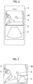
- the display controller 35 executes predetermined processing on the ultrasound image U sent from the image processing unit 32 and displays the ultrasound image U on the HMD-side monitor 36 of the HMD 3 as shown in Fig. 4 under the control of the HMD controller 37.
- Fig. 4 shows an example where a subject P positioned in front of the operator is confirmed by the operator through the HMD-side monitor 36 and the ultrasound image U is displayed on the HMD-side monitor 36 to be superimposed on a part of the field of view in front of the operator.
- the camera unit 33 acquires a view image C obtained by imaging a scanning point of the ultrasound probe 2 in the subject P.
- Te camera unit 33 incorporates the imaging lens F, an image sensor (not shown) that images the scanning point of the ultrasound probe 2 through the imaging lens F to acquire a view image signal as an analog signal, an analog signal processing circuit (not shown) that amplifies the view image signal acquired by the image sensor and converts the view image signal into a digital signal, and a digital signal processing circuit (not shown) that performs various kinds of correction, such as a gain, on the converted digital signal to generate the view image C.
- the analog signal processing circuit and the digital signal processing circuit may be incorporated in an HMD-side processor 39.
- the camera unit 33 sends the generated view image C to the HMD-side wireless communication unit 31.
- the HMD-side wireless communication unit 31 wirelessly transmits the view image C sent to the HMD-side wireless communication unit 31, to the external apparatus 4.
- the HMD controller 37 performs control of each unit of the HMD 3 based on a control program and the like stored in advance.
- an HMD-side storage unit is connected to the HMD controller 37.
- the HMD-side storage unit stores the control program and the like of the HMD 3.
- a flash memory for example, a flash memory, a RAM, an SD card, or an SSD can be used.
- a battery is incorporated in the HMD 3, and power is supplied from the battery to each circuit of the HMD 3.
- the HMD-side processor 39 having the HMD-side wireless communication unit 31, the image processing unit 32, the display controller 35, and the HMD controller 37 is configured with a CPU and a control program causing the CPU to execute various kinds of processing
- the HMD-side processor 39 may be configured using an FPGA, a DSP, an ASIC, a GPU, or other ICs or may be configured by combining such ICs.
- the HMD-side wireless communication unit 31, the image processing unit 32, the display controller 35, and the HMD controller 37 of the HMD-side processor 39 may be configured to be partially or wholly integrated into one CPU or the like.
- the external wireless communication unit 41 of the external apparatus 4 includes an antenna that performs transmission and reception of radio waves, and receives the transmission signal representing the reception data before imaging transmitted from the probe-side wireless communication unit 24 of the ultrasound probe 2 and a transmission signal representing the view image C transmitted from the HMD-side wireless communication unit 31 of the HMD 3 and outputs the reception data before imaging and the view image C by demodulating the received transmission signals under the control of the external controller 46.
- the external wireless communication unit 41 sends the reception data before imaging to the image processing unit 42 and sends the view image C to the image synchronization unit 43.
- the image processing unit 42 raster-converts the reception data before imaging sent from the external wireless communication unit 41 into an image signal conforming to a normal television signal scanning system and executes various kinds of necessary image processing, such as brightness correction, gradation correction, sharpness correction, image size correction, refresh rate correction, scanning frequency correction, and color correction, conforming to a display format for the external monitor 45 on the converted image signal, thereby generating an ultrasound image U.
- the image processing unit 42 sends the generated ultrasound image U to the image synchronization unit 43.
- the image synchronization unit 43 of the external apparatus 4 synchronizes the ultrasound image U sent from the image processing unit 42 and the view image C sent from the external wireless communication unit 41 with each other to generate a composite image M based on the ultrasound image U and the view image C synchronized with each other.
- synchronizing the ultrasound image U and the view image C with each other refers to associating the ultrasound image U and the view image C captured at the same timing with each other.
- the image synchronization unit 43 can synchronize the ultrasound image U and the view image C captured at the same timing with each other by regarding the time stamp of the ultrasound image U as representing a time at which the ultrasound image U is captured, regarding the time stamp of the view image C as representing a time at which the view image C is captured, and referring to the time stamps of the ultrasound image U and the view image C.
- the image synchronization unit 43 can refer to the time stamp of the ultrasound image U and the time stamp of the view image C, and in a case where a difference between the time at which the ultrasound image U is captured and the time at which the view image C is captured is within a given range, for example, within 0.1 seconds, can regard the ultrasound image U and the view image C as being captured at the same timing to perform association.
- the image synchronization unit 34 may refer to the time stamp of the ultrasound image U and the time stamp of the view image C, may select the view image C captured at a time closest to the time at which the ultrasound image U to be associated is captured, and may associate the selected view image C and the ultrasound image U with each other.
- the image synchronization unit 34 may select the ultrasound image U captured at a time closest to the time at which the view image C to be associated is captured, and may associate the selected ultrasound image U and the view image C with each other.
- the image synchronization unit 43 sends the ultrasound image U and the view image C synchronized in this manner to the display controller 44.
- the display controller 44 executes predetermined processing on the composite image M sent from the image synchronization unit 43 and displays the ultrasound image U and the view image C synchronized with each other together on the external monitor 45 of the external apparatus 4 as shown in Fig. 5 under the control of the external controller 46.
- the external monitor 45 displays the ultrasound image U, the view image C, and the like under the control of the display controller 44, and includes, for example, a display device, such as a liquid crystal display (LCD) or an organic electroluminescence display (organic EL display).
- a display device such as a liquid crystal display (LCD) or an organic electroluminescence display (organic EL display).
- the input device 47 of the external apparatus 4 is provided for the operator to perform an input operation, and includes a touch sensor disposed on the external monitor 45 in a superimposed manner.
- the external controller 46 performs control of each unit of the external apparatus 4 based on a control program and the like stored in advance.
- an external apparatus-side storage unit is connected to the external apparatus 4.
- the external apparatus-side storage unit stores the control program and the like of the external apparatus 4.
- a flash memory for example, a flash memory, a RAM, an SD card, or an SSD can be used.
- a battery is incorporated in the external apparatus 4, and power is supplied from the battery to each circuit of the external apparatus 4.
- the external apparatus-side processor 48 having the external wireless communication unit 41, the image processing unit 42, the image synchronization unit 43, the display controller 44, and the external controller 46 is configured with a CPU and a control program causing the CPU to execute various kinds of processing
- the external apparatus-side processor 48 may be constituted using an FPGA, a DSP, an ASIC, a GPU, or other ICs or may be constituted by combining such ICs.
- the external wireless communication unit 41, the image processing unit 42, the image synchronization unit 43, the display controller 44, and the external controller 46 of the external apparatus-side processor 48 may be configured to be partially or wholly integrated into one CPU or the like.
- the ultrasound probe 2 is brought into contact with a body surface of the subject P by the operator, and ultrasonic beams are transmitted from a plurality of transducers of the transducer array 21 into the subject P in response to the drive signals from the pulser 51 of the transmission and reception circuit 22 under the control of the probe controller 26.
- An ultrasound echo based on the transmitted ultrasonic beam is received by each transducer, the reception signal as an analog signal is output to the amplification unit 52 and amplified, and is AD-converted by the AD conversion unit 53, and reception data is acquired.
- the beamformer 54 executes the reception focus processing on the reception data to generate a sound ray signal.
- the signal processing unit 23 converts the generated sound ray signal into reception data before imaging that is a signal representing tomographic image information regarding a tissue in the subject P. In this case, the signal processing unit 23 performs correction of attenuation on the sound ray signal due to a propagation distance depending on a depth of a position where the ultrasonic wave is reflected, and then, executes envelope detection processing.
- the probe-side wireless communication unit 24 wirelessly transmits the generated sound ray signal to the HMD 3 and the external apparatus 4.
- the HMD-side wireless communication unit 31 of the HMD 3 receives the reception data before imaging wirelessly transmitted from the ultrasound probe 2 and sends the received reception data before imaging to the image processing unit 32.
- the image processing unit 32 raster-converts the reception data before imaging sent from the HMD-side wireless communication unit 31 into an image signal conforming to a normal television signal scanning system and executes various kinds of necessary image processing, such as brightness correction, gradation correction, sharpness correction, an image size correction, refresh rate correction, scanning frequency correction, and color correction, conforming to a display format for the HMD-side monitor 36 on the converted image signal, thereby generating the ultrasound image U.
- the ultrasound image U generated in this manner is sent to the display controller 35.
- the display controller 35 executes predetermined processing on the ultrasound image U, then, sends the ultrasound image U to the HMD-side monitor 36, and displays the ultrasound image U on the HMD-side monitor 36 as shown in Fig. 4 .
- the ultrasound image U is displayed on the HMD-side monitor 36 to be superimposed on a part of the field of view in front of the operator, and thus, the operator can simultaneously confirm the field of view in front and the ultrasound image U to easily correspond and recognize the scanning point of the ultrasound probe 2 in the subject P and the tissue in the subject P to be observed at the scanning point.
- An example of Fig. 4 shows a state in which the ultrasound probe 2 is in contact with an abdomen of the subject P as the field of view in front of the operator, and an internal tissue of the abdomen of the subject P is rendered in the ultrasound image U.
- the camera unit 33 of the HMD 3 acquires the view image C obtained by imaging the scanning point of the ultrasound probe 2 in the subject P under the control of the HMD controller 37.
- the operator turns the field of view in front toward the subject P, whereby the view image C obtained by imaging the scanning point of the ultrasound probe 2 in the subject P is acquired by the camera unit 33.
- the view image C acquired in this manner is sent to the HMD-side wireless communication unit 31.
- the HMD-side wireless communication unit 31 wirelessly transmits the view image C sent from the camera unit 33, to the external apparatus 4.
- the external wireless communication unit 41 of the external apparatus 4 receives the reception data before imaging wirelessly transmitted from the ultrasound probe 2 and the view image C wirelessly transmitted from the HMD 3, sends the received reception data before imaging to the image processing unit 42, and sends the received view image C to the image synchronization unit 43.
- the image processing unit 42 raster-converts the reception data before imaging sent from the external wireless communication unit 41 into an image signal conforming to a normal television signal scanning system and executes various kinds of necessary image processing, such as brightness correction, gradation correction, sharpness correction, image size correction, refresh rate correction, scanning frequency correction, and color correction, conforming to a display format for the external monitor 45 on the converted image signal, thereby generating an ultrasound image U.
- the image processing unit 42 sends the generated ultrasound image U to the image synchronization unit 43.
- the image synchronization unit 43 synchronizes the ultrasound image U sent from the image processing unit 42 and the view image C sent from the external wireless communication unit 41 with each other to generate the composite image M in which the ultrasound image U and the view image C synchronized with each other are put together into one image.
- the image synchronization unit 43 can synchronize the ultrasound image U and the view image C captured at the same timing with each other by regarding the time stamp of the ultrasound image U as representing a time at which the ultrasound image U is captured, regarding the time stamp of the view image C as representing a time at which the view image C is captured, and referring to the time stamps of the ultrasound image U and the view image C.
- the time in the HMD 3 and the time in the external apparatus 4 can be shared by each other.
- a time of an internal timepiece may be set using a communication protocol, such as Network Time Protocol (NTP) or Network Identity and Time Zone (NITZ).
- NTP Network Time Protocol
- NITZ Network Identity and Time Zone
- the ultrasound image U and the view image C synchronized with each other by the image synchronization unit 43 are sent as the composite image M to the display controller 44.
- the display controller 44 executes predetermined processing on the composite image M, then, sends the composite image M to the external monitor 45, and displays the ultrasound image U and the view image C together on the external monitor 45 as shown in Fig. 5 .
- An example of Fig. 5 shows that the external apparatus 4 is a mobile thin type computer, such as a so-called smartphone or a tablet, and the view image C and the ultrasound image U are displayed on the upper and lower sides of the external monitor 45 of the external apparatus 4, respectively.
- a state in which the ultrasound probe 2 is in contact with the abdomen of the subject P is rendered in the view image C, and the internal tissue of the abdomen of the subject P is rendered in the ultrasound image U.
- the ultrasound image U is displayed on the HMD-side monitor 36 of the HMD 3 and the view image C and the ultrasound image U synchronized with each other are displayed on the external monitor 45 of the external apparatus 4, the same ultrasound image U is displayed on the HMD-side monitor 36 and the external monitor 45 substantially simultaneously.
- the view image corresponding to the field of view in front to be observed by the operator through the HMD-side monitor 36 is displayed on the external monitor 45 substantially in real time.
- the observer who observes the external monitor 45 can observe the ultrasound image U captured in a site of inspection where the subj ect P and the operator are positioned and the view image corresponding to the field of view in front of the operator substantially in real time.
- the operator who operates the ultrasound probe to capture the ultrasound image may be different from the observer who observes the captured ultrasound image to perform diagnosis.
- the operator since the operator normally needs to operate the ultrasound probe to capture an ultrasound image of an intended part in a subject P while confirming the obtained ultrasound image personally, in particular, in a case where the level of skill of the operator is low, the operator may hardly determine whether or not the intended part of the subject is accurately observed.
- the operator having a low level of skill may not operate the ultrasound probe using appropriate skill involving the hands, and an ultrasound image with low image quality is obtained.
- the same ultrasound image U is displayed on the HMD-side monitor 36 and the external monitor 45 substantially simultaneously, and the view image C corresponding to the field of view in front of the operator is displayed on the external monitor 45 substantially in real time.
- the observer who observes the external monitor 45 can observe the view image C and the ultrasound image U captured in a site of inspection where the subject and the operator are positioned, substantially in real time.
- the observer having a high level of skill can give advice to the operator in real time, even in a case where the level of skill of the operator positioned at a remote location with respect to the observer is low, an appropriate ultrasound image U is obtained, and it is possible to improve accuracy of ultrasound diagnosis.
- the observer who is positioned at a remote location with respect to the operator and has a low level of skill can also be made to confirm the view image C representing a state in which the operator having a high level of skill operates the ultrasound probe 2 and the appropriate ultrasound image U corresponding to the view image C.
- the ultrasound system 1 according to Embodiment 1 of the present invention is considerably useful even from a viewpoint of training.
- the operator since the ultrasound image U is displayed on the HMD-side monitor 36 of the HMD 3, the operator can confirm the ultrasound image U while confirming the field of view in front.
- the view image C is captured by the camera unit 33 of the HMD 3, the operator does not need to use hands to capture the view image C.
- the operator can perform more various inspections, such as performing skill involving the hands to insert a so-called puncture needle into the subject P using the other hand while operating the ultrasound probe 2 using one hand, without separating the line of sight from the subj ect P.
- the signal processing unit 23 of the ultrasound probe 2 may give a time stamp to the signal subjected to the envelope detection processing.
- the time in the ultrasound probe 2 and the time in the HMD 3 are shared by each other, whereby it is possible to synchronize the ultrasound image U generated by the image processing unit 32 of the HMD 3 and the view image C generated by the camera unit 33 with each other based on the signal given the time stamp, and to synchronize the ultrasound image U generated by the image processing unit 42 of the external apparatus 4 and the view image C generated by the camera unit 33 with each other.
- the time in the ultrasound probe 2 and the time in the HMD 3 can be shared, for example, with the ultrasound probe 2 or the HMD 3 as a reference.
- the time of the internal timepiece may be set using a communication protocol, such as NTP or NITZ.
- a method of synchronizing the ultrasound image U and the view image C with each other is not limited to the method using the time stamp described above.
- an imaging timing of the ultrasound image U by the ultrasound probe 2 and an imaging timing of the view image C by the camera unit 33 of the HMD 3 are synchronized with each other, and a time difference between the time at which the ultrasound image U is captured and the time at which the view image C is captured is within a given range, for example, within 0.1 seconds
- the image synchronization unit 43 of the external apparatus 4 can regard that the ultrasound image U and the view image C are captured at the same timing, and can synchronize the ultrasound image U and the view image C with each other.
- each of the ultrasound image U and the view image C synchronized with each other may be sent to the display controller 44.
- the display controller 44 executes predetermined processing on each of the ultrasound image U and the view image C sent from the image synchronization unit 43 and displays the ultrasound image U and the view image C synchronized with each other together on the external monitor 45, for example, as shown in Fig. 5 .
- the observer who views the external monitor 45 can observe the view image C and the ultrasound image U captured in a site of inspection where the subject P and the operator are positioned, substantially in real time.
- the HMD 3 may comprise an eye camera unit that images eyes of the operator, and an eye movement detection unit that analyzes an eye image representing the eyes of the operator captured by the eye camera unit to detect a wink, the line of sight, or the like of the operator.
- the detected wink and movement of the light of sight of the operator can be used, for example, as an input operation of the operator.
- the number of winks, the position of the light of sight, or the like of the operator detected by the eye movement detection unit can be used as a trigger or the like of imaging start and imaging stop of the view image C by the camera unit 33.
- the wink, the movement of the light of sight, or the like of the operator is used as an input operation, whereby it is possible to allow the operator to perform an input operation without using the hands even in a case where both hands are used during inspection of the subject P.
- the ultrasound probe 2 and the HMD 3 are connected to each other by wireless communication, for example, the ultrasound probe 2 and the HMD 3 may be connected to each other by wired communication, instead of being connected by wireless communication.
- the external apparatus 4 is a mobile thin type computer, such as a so-called smartphone or a tablet, has been illustrated, the external apparatus 4 is not limited thereto.
- a so-called notebook type personal computer, a stationary type personal computer, or the like may be used as the external apparatus 4.
- the transmission and reception circuit 22 has the beamformer 54 together with the amplification unit 52 and the AD conversion unit 53, the beamformer 54 may be disposed between the transmission and reception circuit 22 and the signal processing unit 23, not inside the transmission and reception circuit 22.
- the probe-side processor 27 may configure the beamformer 54.
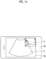
- external input information such as a cursor A that is movable by an input operation of the observer through the input device 47 of the external apparatus 4
- the cursor A displayed on the external monitor 45 of the external apparatus 4 is moved by an input operation of the observer through the input device 47 of the external apparatus 4
- the cursor A displayed on the terminal monitor 36 of the mobile information terminals is moved similarly.
- the observer having a high level of skill who observes the ultrasound image U and the view image C on the external monitor 45 of the external apparatus 4 can easily support inspection that is performed by the operator, such as indicating a position where the ultrasound probe 2 is to be scanned, to the operator having a low level of skill of the ultrasound probe 2 and the HMD 3 using the cursor A.
- the cursor A that is movable by an input operation of the operator may displayed on the HMD-side monitor 36 of the HMD 3 and the external monitor 45 of the external apparatus 4 simultaneously.
- the operator having a high level of skill can perform training on ultrasound diagnosis for the observer having a low level of skill positioned close to the external apparatus 4 more easily and in more detail.
- the shape of the cursor A is not limited to an arrow shape, and can have any shape, such as a circular shape or a polygonal shape.
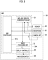
- Fig. 8 shows the configuration of an HMD 3A in a modification example of Embodiment 1 of the present invention.
- the HMD 3A is further provided with a microphone 61 and a speaker 62, comprises an HMD controller 37A instead of the HMD controller 37, and comprises an HMD-side processor 39A instead of the HMD-side processor 39, compared to the HMD 3 shown in Fig. 1 .
- the microphone 61 and the speaker 62 are connected to the HMD-side wireless communication unit 31.
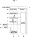
- Fig. 9 shows the configuration of an external apparatus 4A in the modification example of Embodiment 1 of the present invention.
- the external apparatus 4A is further provided with a microphone 63 and a speaker 64, comprises an external controller 46A instead of the external controller 46, and comprises an external apparatus-side processor 48A instead of the external apparatus-side processor 48, compared to the external apparatus 4 shown in Fig. 1 .
- the microphone 63 and the speaker 64 are connected to the external wireless communication unit 41.
- voice data is transmitted and received between the HMD 3A and the external apparatus 4A in two directions.
- the uttered voice is input to the microphone 61 of the HMD 3A, and voice data is generated by the microphone 61.
- the generated voice data is wirelessly transmitted from the HMD-side wireless communication unit 31 to the external apparatus 4A.
- the external wireless communication unit 41 of the external apparatus 4A receives the voice data wirelessly transmitted from the HMD 3A and sends the received voice data to the speaker 64.
- the speaker 64 reproduces the voice uttered by the operator of the ultrasound probe 2 and the HMD 3A based on the voice data received from the external wireless communication unit 41.
- the observer who observes the ultrasound image U and the view image C on the external monitor 45 of the external apparatus 4A utters voice toward the external apparatus 4A, the uttered voice is input to the microphone 63 of the external apparatus 4A, and voice data is generated by the microphone 63.
- the generated voice data is wirelessly transmitted from the external wireless communication unit 41 to the HMD 3A.
- the HMD-side wireless communication unit 31 of the HMD 3A receives the voice data wirelessly transmitted from the external apparatus 4A and sends the received voice data to the speaker 62.
- the speaker 62 reproduces the voice uttered by the observer positioned close to the external apparatus 4 based on the voice data received from the HMD-side wireless communication unit 31.
- the voice data is transmitted and received between the HMD 3A and the external apparatus 4A in two directions, whereby it is possible to perform more detailed information sharing between the operator of the ultrasound probe 2 and the HMD 3A and the observer positioned close to the external apparatus 4A.
- the observer having a high level of skill who observes the ultrasound image U and the view image C on the external monitor 45 of the external apparatus 4A can give advice to the operator having a low level of skill of the ultrasound probe 2 and the HMD 3A more easily and in more detail.
- the operator having a high level of skill can perform training on ultrasound diagnosis for the observer having a low level of skill positioned close to the external apparatus 4A more easily and in more detail.
- the voice of the operator input to the microphone 61 of the HMD 3A may be used as an input operation of the operator.
- the HMD controller 37A can acquire instruction information by analyzing the voice data generated based on the voice of the operator by the microphone 61 and can perform control of each unit of the HMD 3A, such as imaging start and imaging stop of the view image C by the camera unit 33, conforming to the acquired instruction information.
- the control of the ultrasound probe 2 may be performed based on the voice data analyzed by the HMD controller 37A.
- the voice data analyzed by the HMD controller 37A is wirelessly transmitted as input information from the operator from the HMD-side wireless communication unit 31 to the ultrasound probe 2, and is input to the probe controller 26 by way of the probe-side wireless communication unit 24.
- the probe controller 26 can perform control of each unit of the ultrasound probe 2, such as transmission start and transmission stop of ultrasonic waves by the transducer array 21.
- the voice of the observer input to the microphone 63 of the external apparatus 4A may be used as an input operation of the observer.
- the external controller 46A may acquire instruction information by analyzing the voice data generated based on the voice of the observer by the microphone 63 and may perform control of each unit of the head-mounted display 3A, such as imaging start and imaging stop of the view image C by the camera unit 33 of the head-mounted display 3A, and control of each unit of the ultrasound probe 2, such as transmission start and transmission stop of ultrasonic waves by the transducer array 21 of the ultrasound probe 2.
- Embodiment 1 although the reception data before imaging obtained by performing the envelope detection processing on the sound ray signal is generated in the ultrasound probe 2, and the generated reception data before imaging is wirelessly transmitted to the HMD 3 and the external apparatus 4, the ultrasound image U may be generated in the ultrasound probe 2, and the generated ultrasound image U may be wirelessly transmitted to the HMD 3 and the external apparatus 4.
- Fig. 10 shows the configuration of an ultrasound system 1B according to Embodiment 2 of the present invention.
- the ultrasound system 1B comprises an ultrasound probe 2B instead of the ultrasound probe 2, comprises an HMD 3B instead of the HMD 3, and comprises an external apparatus 4B instead of the external apparatus 4, compared to the ultrasound system 1 of Embodiment 1 shown in Fig. 1 .
- the ultrasound probe 2B is further provided with an image processing unit 71, comprises a probe controller 26B instead of the probe controller 26, and a probe-side processor 27B instead of the probe-side processor 27, compared to the ultrasound probe 2 in Embodiment 1.
- the image processing unit 71 is connected to the signal processing unit 23.
- the probe-side wireless communication unit 24 and the probe controller 26B are connected to the image processing unit 71.
- the signal processing unit 23 and the image processing unit 71 configure an ultrasound image generation unit.
- the HMD 3B is not provided with the image processing unit 32, comprises an HMD controller 37B instead of the HMD controller 37, and comprises an HMD-side processor 39B instead of the HMD-side processor 39, compared to the HMD 3 in Embodiment 1.
- the display controller 35 and the camera unit 33 are connected to the HMD-side wireless communication unit 31.
- the external apparatus 4B is not provided with the image processing unit 42, comprises an external controller 46B instead of the external controller 46, and comprises an external apparatus-side processor 48B instead of the external apparatus-side processor 48, compared to the external apparatus 4 in Embodiment 1.
- the image processing unit 71 of the ultrasound probe 2B raster-converts the signal subjected to the envelope detection processing by the signal processing unit 23 into an image signal conforming to a normal television signal scanning system and executes various kinds of necessary image processing, such as brightness correction, gradation correction, sharpness correction, an image size correction, refresh rate correction, scanning frequency correction, and color correction, on the converted image signal, thereby generating an ultrasound image U conforming to a display format for the HMD-side monitor 36 of the HMD 3B and an ultrasound image U conforming to a display format for the external monitor 45 of the external apparatus 4B.
- necessary image processing such as brightness correction, gradation correction, sharpness correction, an image size correction, refresh rate correction, scanning frequency correction, and color correction
- the image processing unit 71 wirelessly transmits the ultrasound image U conforming to the display format for the HMD-side monitor 36 of the HMD 3B from the probe-side wireless communication unit 24 to the HMD 3B and wirelessly transmits the ultrasound image U conforming to the display format for the external monitor 45 of the external apparatus 4B from the probe-side wireless communication unit 24 to the external apparatus 4B.
- the HMD-side wireless communication unit 31 of the HMD 3B receives the ultrasound image U wirelessly transmitted from the ultrasound probe 2B and sends the received ultrasound image U to the display controller 35.
- the display controller 35 executes predetermined processing on the ultrasound image U sent from the HMD-side wireless communication unit 31, then, sends the ultrasound image U to the HMD-side monitor 36, and displays the ultrasound image U on the HMD-side monitor 36 as shown in Fig. 4 .
- the external wireless communication unit 41 of the external apparatus 4B receives the ultrasound image U wirelessly transmitted from the ultrasound probe 2B and the view image C wirelessly transmitted from the HMD 3B and sends the received ultrasound image U and view image C to the image synchronization unit 43.
- the image synchronization unit 43 synchronizes the ultrasound image U and the view image C sent from the external wireless communication unit 41 with each other and generates a composite image M based on the ultrasound image U and the view image C synchronized with each other.
- the display controller 44 executes predetermined processing on the composite image M generated by the image synchronization unit 43, then, sends the composite image M to the external monitor 45, and displays the ultrasound image U and the view image C synchronized with each other together on the external monitor 45 as shown in Fig. 5 .
- the ultrasound probe 2B comprises the image processing unit 71
- the HMD 3 comprises the image processing unit 32
- the external apparatus 4 comprises the image processing unit 42
- the same ultrasound image U is displayed on the HMD-side monitor 36 and the external monitor 45 substantially simultaneously
- the ultrasound probe 2B and the view image C corresponding to the field of view in front of the operator of the HMD 3B are displayed on the external monitor 45 substantially in real time.
- the observer who observes the view image C and the ultrasound image U with the external apparatus 4B disposed at a remote location can give advice to the operator of the ultrasound probe 2B and the HMD 3B, an appropriate ultrasound image U is obtained, and it is possible to improve accuracy of ultrasound diagnosis.
- the HMD 3 comprises the image processing unit 32 and the external apparatus 4 comprises the image processing unit 42.
- the ultrasound probe 2B comprises the image processing unit 71.
- the HMD 3B and the external apparatus 4B do not need to have the image processing units 32 and 42, respectively, and the internal configurations of the HMD 3B and the external apparatus 4B are simplified compared to the internal configurations of the HMD 3 and the external apparatus 4 in the ultrasound system 1 of Embodiment 1. For this reason, with the ultrasound system 1B according to Embodiment 2, it is possible to reduce power consumption, calculation load, and the like of the HMD 3B and the external apparatus 4B compared to the ultrasound system 1 of Embodiment 1.
- Embodiment 1 although the ultrasound image U and the view image C are synchronized in the external apparatus 4, for example, the ultrasound image U and the view image C may be synchronized in the HMD 3.
- Fig. 11 shows the configuration of an ultrasound system 1C according to Embodiment 3 of the present invention.
- the ultrasound system 1C comprises an ultrasound probe 2C having the same internal configuration as the ultrasound probe 2, comprises an HMD 3C instead of the HMD 3, and comprises an external apparatus 4C instead of the external apparatus 4, compared to the ultrasound system 1 of Embodiment 1 shown in Fig. 1 .
- the ultrasound probe 2C is connected only to the HMD 3C by wireless communication, and the external apparatus 4C is connected only to the HMD 3C by wireless communication.
- the HMD 3C is further provided with an image synchronization unit 34, comprises an HMD controller 37C instead of the HMD controller 37, and comprises an HMD-side processor 39C instead of the HMD-side processor 39, compared to the HMD 3 in Embodiment 1.
- the image synchronization unit 34 is connected to the HMD-side wireless communication unit 31, the image processing unit 32, and the camera unit 33.
- the display controller 35 is connected to the image synchronization unit 34.
- the external apparatus 4C is not provided with the image processing unit 42 and the image synchronization unit 43, comprises an external controller 46C instead of the external controller 46, and comprises an external apparatus-side processor 48C instead of the external apparatus-side processor 48, compared to the external apparatus 4 in Embodiment 1.
- the display controller 44 is connected to the external wireless communication unit 41.
- the probe-side wireless communication unit 24 of the ultrasound probe 2C wirelessly transmits the reception data before imaging subjected to the envelope detection processing by the signal processing unit 23 only to the HMD 3C.
- the HMD-side wireless communication unit 31 of the HMD 3C receives the reception data before imaging wirelessly transmitted from the ultrasound probe 2C and sends the received reception data before imaging to the image processing unit 32.
- the image processing unit 32 raster-converts the reception data before imaging sent from the HMD-side wireless communication unit 31 into an image signal conforming to a normal television signal scanning system and executes various kinds of necessary image processing, such as brightness correction, gradation correction, sharpness correction, an image size correction, refresh rate correction, scanning frequency correction, and color correction, on the converted image signal, thereby generating an ultrasound image U conforming to a display format for the HMD-side monitor 36 of the HMD 3C and an ultrasound image U conforming to a display format for the external monitor 45 of the external apparatus 4C.
- necessary image processing such as brightness correction, gradation correction, sharpness correction, an image size correction, refresh rate correction, scanning frequency correction, and color correction
- the image processing unit 32 sends the ultrasound image U conforming to the display format for the HMD-side monitor 36 of the HMD 3C to the display controller 35 by way of the image synchronization unit 34 and sends the ultrasound image U conforming to the display format for the external monitor 45 of the external apparatus 4C to the image synchronization unit 34.
- the display controller 35 executes predetermined processing on the ultrasound image U conforming to the display format for the HMD-side monitor 36 sent from the image processing unit 32 by way of the image synchronization unit 34, and then, displays the ultrasound image U on the HMD-side monitor 36 as shown in Fig. 4 .
- the camera unit 33 acquires a view image C obtained by imaging a scanning point of the ultrasound probe 2C in the subject P and sends the acquired view image C to the image synchronization unit 34.
- the image synchronization unit 34 synchronizes the ultrasound image U sent from the image processing unit 32 and the view image C sent from the camera unit 33 with each other and generates a composite image M based on the ultrasound image U and the view image C synchronized with each other.
- the image synchronization unit 34 sends the composite image M generated based on the ultrasound image U conforming to the display format for the external monitor 45 of the external apparatus 4C and the view image C to the HMD-side wireless communication unit 31.
- the HMD-side wireless communication unit 31 wirelessly transmits the composite image M sent from the image synchronization unit 34, to the external apparatus 4C.
- the external wireless communication unit 41 of the external apparatus 4C receives the composite image M wirelessly transmitted from the HMD 3C and sends the received composite image M to the display controller 44.
- the display controller 44 executes predetermined processing on the composite image M sent from the external wireless communication unit 41, then, sends the composite image M to the external monitor 45, and displays the ultrasound image U and the view image C synchronized with each other together on the external monitor 45 as shown in Fig. 5 .
- the ultrasound system 1C according to Embodiment 3 of the present invention even in a case where only the HMD 3C comprises the image processing unit 32 and the image synchronization unit 34, similarly to the ultrasound system 1 of Embodiment 1 in which the HMD 3 comprises the image processing unit 32 and the external apparatus 4 comprises the image processing unit 42 and the image synchronization unit 43, the same ultrasound image U is displayed on the HMD-side monitor 36 and the external monitor 45 substantially simultaneously, and the ultrasound probe 2C and the view image C corresponding to the field of view in front of the operator of the HMD 3C are displayed on the external monitor 45 substantially in real time.
- the observer who observes the view image C and the ultrasound image U with the external apparatus 4C disposed at a remote location can give advice to the operator of the ultrasound probe 2C and the HMD 3C, an appropriate ultrasound image U is obtained, and it is possible to improve accuracy of ultrasound diagnosis.
- the external apparatus 4 comprises the image processing unit 42 and the image synchronization unit 43.
- the composite image M generated based on the ultrasound image U and the view image C is wirelessly transmitted from the HMD 3C to the external apparatus 4C.
- the external apparatus 4C does not need to have the image processing unit 42 and the image synchronization unit 43, and the internal configuration of the external apparatus 4C is simplified compared to the internal configuration of the external apparatus 4 in Embodiment 1. For this reason, with the ultrasound system 1C according to Embodiment 3, it is possible to reduce power consumption, calculation load, and the like of the external apparatus 4C.
- the ultrasound image U may be generated in the ultrasound probe 2.
- Fig. 12 shows the configuration of an ultrasound system 1D according to Embodiment 4 of the present invention.
- the ultrasound system 1D comprises an ultrasound probe 2D instead of the ultrasound probe 2C, comprises an HMD 3D instead of the HMD 3C, and comprises an external apparatus 4D instead of the external apparatus 4C, compared to the ultrasound system 1C of Embodiment 3 shown in Fig. 11 .
- the ultrasound probe 2D is connected only to the HMD 3D by wireless communication
- the external apparatus 4D is connected only to the HMD 3D by wireless communication.
- the ultrasound probe 2D is further provided with an image processing unit 81, comprises a probe controller 26D instead of the probe controller 26, and comprises a probe-side processor 27D instead of the probe-side processor 27, compared to the ultrasound probe 2C in Embodiment 3.
- the image processing unit 81 is connected to the signal processing unit 23, and the probe-side wireless communication unit 24 and the probe controller 26D are connected to the image processing unit 81.
- the signal processing unit 23 and the image processing unit 81 configure an ultrasound image generation unit.
- the HMD 3D is not provided with the image processing unit 32, comprises an HMD controller 37D instead of the HMD controller 37C, and comprises an HMD-side processor 39D instead of the HMD-side processor 39C, compared to the HMD 3C in Embodiment 3.
- the image synchronization unit 34 is connected to the HMD-side wireless communication unit 31.
- the camera unit 33 is connected to the image synchronization unit 34.
- the external apparatus 4D comprises an external controller 46D instead of the external controller 46C and comprise an external apparatus-side processor 48D instead of the external apparatus-side processor 48C, compared to the external apparatus 4C in Embodiment 3.
- the image processing unit 81 of the ultrasound probe 2D raster-converts the signal subjected to the envelop detection processing by the signal processing unit 23 into an image signal conforming to a normal television signal scanning system and executes various kinds of necessary image processing, such as brightness correction, gradation correction, sharpness correction, an image size correction, refresh rate correction, scanning frequency correction, and color correction, on the converted image signal, thereby generating an ultrasound image U conforming to a display format for the HMD-side monitor 36 of the HMD 3D and an ultrasound image U conforming to a display format for the external monitor 45 of the external apparatus 4D.
- the image processing unit 81 sends the generated ultrasound images U to the probe-side wireless communication unit 24.
- the probe-side wireless communication unit 24 wirelessly transmits the ultrasound image U sent from the image processing unit 81 to the HMD 3D.
- the HMD-side wireless communication unit 31 receives the ultrasound image U wirelessly transmitted from the ultrasound probe 2D.
- the HMD-side wireless communication unit 31 sends the ultrasound image U conforming to the display format for the HMD-side monitor 36 to the display controller 35 by way of the image synchronization unit 34 and sends the ultrasound image U conforming to the display format for the external monitor 45 to the image synchronization unit 34.
- the display controller 35 executes predetermined processing on the ultrasound image U sent from the HMD-side wireless communication unit 31 by way of the image synchronization unit 34 and displays the ultrasound image U on the HMD-side monitor 36 as shown in Fig. 4 .
- the camera unit 33 acquires a view image C obtained by imaging a scanning point of the ultrasound probe 2D in the subject P and sends the acquired view image C to the image synchronization unit 34.
- the image synchronization unit 34 synchronizes the ultrasound image U sent from the HMD-side wireless communication unit 31 and the view image C sent from the camera unit 33 with each other and generates a composite image M based on the ultrasound image U and the view image C synchronized with each other.
- the image synchronization unit 34 sends the composite image M generated based on the ultrasound image U conforming to the display format for the external monitor 45 and the view image C synchronized with each other to the HMD-side wireless communication unit 31.
- the HMD-side wireless communication unit 31 wirelessly transmits the composite image M sent from the image synchronization unit 34 to the external apparatus 4D.
- the external wireless communication unit 41 of the external apparatus 4D receives the composite image M wirelessly transmitted from the HMD 3D and sends the received composite image M to the display controller 44.
- the display controller 44 executes predetermined processing on the composite image M sent from the external wireless communication unit 41, then, sends the composite image M to the external monitor 45, and displays the ultrasound image U and the view image C synchronized with each other together on the external monitor 45 as shown in Fig. 5 .
- the ultrasound system 1D according to Embodiment 4 even in a case where only the ultrasound probe 2D comprises the image processing unit 81 and only the HMD 3D comprises the image synchronization unit 34, similarly to the ultrasound system 1 of Embodiment 1 in which the HMD 3 comprises the image processing unit 32 and the external apparatus 4 comprises the image processing unit 42 and the image synchronization unit 43, the same ultrasound image U is displayed on the HMD-side monitor 36 and the external monitor 45 substantially simultaneously, and the ultrasound probe 2C and the view image C corresponding to the field of view in front of the operator of the HMD 3C are displayed on the external monitor 45 substantially in real time.
- the observer who observes the view image C and the ultrasound image U with the external apparatus 4D disposed at a remote location can give advice to the operator of the ultrasound probe 2D and the HMD 3D, an appropriate ultrasound image U is obtained, and it is possible to improve accuracy of ultrasound diagnosis.
- Embodiment 3 since the external apparatus 4C receives the composite image M from the HMD 3C and displays the received composite image M on the external monitor 45, the disposition and the size of the ultrasound image U and the view image C displayed on the external monitor 45 cannot be freely changed on the external apparatus 4C side. In contrast, with an ultrasound system 1E of Embodiment 5 shown in Fig. 13 , the disposition and the size of the ultrasound image U and the view image C displayed on the external monitor 45 can be arbitrarily changed on the external apparatus 4E side.
- Fig. 13 shows the configuration of an ultrasound system 1E according to Embodiment 5 of the present invention.
- the ultrasound system 1E comprises an ultrasound probe 2E having the same internal configuration as the ultrasound probe 2C, comprises an HMD 3E instead of the HMD 3C, and comprises an external apparatus 4E instead of the external apparatus 4C, compared to the ultrasound system 1C of Embodiment 3.
- the ultrasound probe 2E is connected only to the HMD 3E by wireless communication, and the external apparatus 4E is connected only to the HMD 3E by wireless communication.
- the HMD 3E comprises an HMD controller 37E instead of the HMD controller 37, and comprises an HMD-side processor 39E instead of the HMD-side processor 39, compared to the HMD 3C in Embodiment 3.
- the image synchronization unit 34 is connected to the HMD-side wireless communication unit 31, the image processing unit 32, and the camera unit 33, and the display controller 35 is connected to the image synchronization unit 34.
- the external apparatus 4E comprises an external controller 46E instead of the external controller 46 and comprises an external apparatus-side processor 48E instead of the external apparatus-side processor 48, compared to the external apparatus 4C in Embodiment 3.
- the probe-side wireless communication unit 24 of the ultrasound probe 2E wirelessly transmit the reception data before imaging subjected to the envelope detection processing by the signal processing unit 23 to the HMD 3E.
- the HMD-side wireless communication unit 31 of the HMD 3E receives the reception data before imaging wirelessly transmitted from the ultrasound probe 2E and sends the received reception data before imaging to the image processing unit 32.
- the image processing unit 32 generates an ultrasound image U conforming to a display format for the HMD-side monitor 36 of the HMD 3E and an ultrasound image U conforming to a display format for the external monitor 45 of the external apparatus 4E based on the reception data before imaging sent from the HMD-side wireless communication unit 31.
- the image processing unit 32 sends the ultrasound image U conforming to the display format for the HMD-side monitor 36 to the display controller 35 by way of the image synchronization unit 34 and sends the ultrasound image U conforming to the display format for the HMD-side monitor 36 to the image synchronization unit 34.
- the display controller 35 executes predetermined processing on the ultrasound image U sent from the image processing unit 32 by way of the image synchronization unit 34, and then, displays the ultrasound image U on the HMD-side monitor 36 as shown in Fig. 4 .
- the camera unit 33 acquires a view image C obtained by imaging a scanning point of the ultrasound probe 2E in the subject P and sends the acquired view image C to the image synchronization unit 34.
- the image synchronization unit 34 synchronizes the ultrasound image U sent from the HMD-side wireless communication unit 31 and the view image C sent from the camera unit 33 with each other.
- the image synchronization unit 34 sends each of the ultrasound image U and the view image C to the HMD-side wireless communication unit 31, instead of generating one composite image M based on the ultrasound image U conforming to the display format for the external monitor 45 and the view image C synchronized with each other.
- the HMD-side wireless communication unit 31 wirelessly transmits the ultrasound image U and the view image C sent from the image synchronization unit 34 to the external apparatus 4E.
- the external wireless communication unit 41 of the external apparatus 4E receives the ultrasound image U and the view image C wirelessly transmitted from the HMD 3E and sends each of the received ultrasound image U and view image C to the display controller 44.
- the display controller 44 executes predetermined processing on the ultrasound image U and the view image C sent from the external wireless communication unit 41 and displays the ultrasound image U and the view image C synchronized with each other together on the external monitor 45.
- the disposition and the size of the ultrasound image U and the view image C displayed on the external monitor 45 can be adjusted by an input operation of the observer through the input device 47.
- the input instruction information is input to the display controller 44 by way of the external controller 46E.
- the display controller 44 displays the ultrasound image U and the view image C synchronized with each other, for example, with the disposition and the size as shown in Fig. 14 based on the input instruction information. In an example shown in Fig.
- the external apparatus 4E, the ultrasound image U, and the view image C are rotated at 90 degrees, and the ultrasound image U and the view image C are displayed on the external monitor 45 such that the view image C is superimposed on a part of the ultrasound image U, compared to the example shown in Fig. 5 .
- the disposition and the size of the ultrasound image U and the view image C displayed on the external monitor 45 of the external apparatus 4E can be adjusted.
- the observer who observes the ultrasound image U and the view image C displayed on the external monitor 45 can more clearly confirm the ultrasound image U and the view image C conforming to the observer's preference.
- the ultrasound image U may be generated in the ultrasound probe 2.
- Fig. 15 shows the configuration of an ultrasound system 1F according to Embodiment 6 of the present invention.
- the ultrasound system 1F comprises an ultrasound probe 2F instead of the ultrasound probe 2E, comprises an HMD 3F instead of the HMD 3E, and comprises an external apparatus 4F instead of the external apparatus 4E, compared to the ultrasound system 1E according to Embodiment 5 shown in Fig. 13 .
- the ultrasound probe 2F is connected only to the HMD 3F by wireless communication
- the external apparatus 4F is connected only to the HMD 3F by wireless communication.
- the ultrasound probe 2F is further provided with an image processing unit 91, comprises a probe controller 26F instead of the probe controller 26, and comprises a probe-side processor 27F instead of the probe-side processor 27, compared to the ultrasound probe 2E in Embodiment 5.
- the image processing unit 91 is connected to the signal processing unit 23, and the probe-side wireless communication unit 24 and the probe controller 26F are connected to the image processing unit 91.
- the signal processing unit 23 and the image processing unit 91 configure an ultrasound image generation unit.
- the HMD 3F is not provided with the image processing unit 32, comprises an HMD controller 37F instead of the HMD controller 37E, and comprises an HMD-side processor 39F instead of the HMD-side processor 39E, compared to the HMD 3E in Embodiment 5.
- the image synchronization unit 34 is connected to the HMD-side wireless communication unit 31.
- the camera unit 33 is connected to the image synchronization unit 34.
- the external apparatus 4F comprises an external controller 46F instead of the external controller 46E and comprises an external apparatus-side processor 48F instead of the external apparatus-side processor 48E, compared to the external apparatus 4E in Embodiment 5.
- the image processing unit 91 of the ultrasound probe 2F raster-converts the signal subjected to the envelope detection processing by the signal processing unit 23 into an image signal conforming to a normal television signal scanning system and executes various kinds of necessary image processing, such as brightness correction, gradation correction, sharpness correction, an image size correction, refresh rate correction, scanning frequency correction, and color correction, on the converted image signal, thereby generating an ultrasound image U conforming to the display format for the HMD-side monitor 36 of the HMD 3F and an ultrasound image U conforming to a display format for the external monitor 45 of the external apparatus 4F.
- the image processing unit 91 sends the generated ultrasound images U to the probe-side wireless communication unit 24.
- the HMD-side wireless communication unit 31 receives the ultrasound image U wirelessly transmitted from the ultrasound probe 2F.
- the HMD-side wireless communication unit 31 sends the ultrasound image U conforming to the display format for the HMD-side monitor 36 to the display controller 35 by way of the image synchronization unit 34 and sends the ultrasound image U conforming to the display format for the external monitor 45 to the image synchronization unit 34.
- the display controller 35 executes predetermined processing on the ultrasound image U sent from the HMD-side wireless communication unit 31 by way of the image synchronization unit 34 and displays the ultrasound image U on the HMD-side monitor 36 as shown in Fig. 4 .
- the camera unit 33 acquires a view image C obtained by imaging a scanning point of the ultrasound probe 2F in the subject P and sends the acquired view image C to the image synchronization unit 34.
- the image synchronization unit 34 synchronizes the ultrasound image U sent from the HMD-side wireless communication unit 31 and the view image C sent from the camera unit 33 with each other.
- the image synchronization unit 34 sends each of the ultrasound image U and the view image C to the HMD-side wireless communication unit 31, instead of generating one composite image M based on the ultrasound image U conforming to the display format for the external monitor 45 and the view image C synchronized with each other.
- the HMD-side wireless communication unit 31 wirelessly transmits the ultrasound image U and the view image C sent from the image synchronization unit 34 to the external apparatus 4F.
- the external wireless communication unit 41 of the external apparatus 4F receives the ultrasound image U and the view image C wirelessly transmitted from the HMD 3F and sends each of the received ultrasound image U and view image C to the display controller 44.
- the display controller 44 executes predetermined processing on the ultrasound image U and the view image C sent from the external wireless communication unit 41 and displays the ultrasound image U and the view image C synchronized with each other together on the external monitor 45.
- the display controller 44 can adjust the disposition and the size of the ultrasound image U and the view image C displayed on the external monitor 45 in response to an input operation of the observer through the input device 47.
- the ultrasound image U and the view image C synchronized with each other are displayed together on the external monitor 45.
- the ultrasound system 1F according to Embodiment 6 of the present invention even in a case where the ultrasound probe 2F comprises the image processing unit 91, the disposition and the size of the ultrasound image U and the view image C displayed on the external monitor 45 of the external apparatus 4F can be adjusted.
- the observer who observes the ultrasound image U and the view image C displayed on the external monitor 45 can more clearly confirm the ultrasound image U and the view image C conforming to the observer's preference.
Landscapes
- Health & Medical Sciences (AREA)
- Life Sciences & Earth Sciences (AREA)
- Engineering & Computer Science (AREA)
- Radiology & Medical Imaging (AREA)
- Heart & Thoracic Surgery (AREA)
- Veterinary Medicine (AREA)
- Public Health (AREA)
- Biophysics (AREA)
- Nuclear Medicine, Radiotherapy & Molecular Imaging (AREA)
- Pathology (AREA)
- General Health & Medical Sciences (AREA)
- Biomedical Technology (AREA)
- Physics & Mathematics (AREA)
- Medical Informatics (AREA)
- Molecular Biology (AREA)
- Surgery (AREA)
- Animal Behavior & Ethology (AREA)
- Computer Networks & Wireless Communication (AREA)
- Multimedia (AREA)
- Signal Processing (AREA)
- Computer Vision & Pattern Recognition (AREA)
- Gynecology & Obstetrics (AREA)
- Ultra Sonic Daignosis Equipment (AREA)
Applications Claiming Priority (2)
| Application Number | Priority Date | Filing Date | Title |
|---|---|---|---|
| JP2019149058 | 2019-08-15 | ||
| PCT/JP2020/027756 WO2021029180A1 (ja) | 2019-08-15 | 2020-07-17 | 超音波システムおよび超音波システムの制御方法 |
Publications (3)
| Publication Number | Publication Date |
|---|---|
| EP4014888A1 EP4014888A1 (en) | 2022-06-22 |
| EP4014888A4 EP4014888A4 (en) | 2022-10-05 |
| EP4014888B1 true EP4014888B1 (en) | 2024-11-06 |
Family
ID=74571018
Family Applications (1)
| Application Number | Title | Priority Date | Filing Date |
|---|---|---|---|
| EP20852377.9A Active EP4014888B1 (en) | 2019-08-15 | 2020-07-17 | Ultrasonic system and method for controlling ultrasonic system |
Country Status (5)
| Country | Link |
|---|---|
| US (1) | US20220133281A1 (https=) |
| EP (1) | EP4014888B1 (https=) |
| JP (2) | JP7315678B2 (https=) |
| CN (1) | CN114206225A (https=) |
| WO (1) | WO2021029180A1 (https=) |
Families Citing this family (7)
| Publication number | Priority date | Publication date | Assignee | Title |
|---|---|---|---|---|
| EP4256370B1 (en) * | 2020-12-01 | 2025-10-08 | Koninklijke Philips N.V. | Retrospective transmit focusing using a transmit speed systems, devices, and methods |
| JP7823490B2 (ja) * | 2022-05-06 | 2026-03-04 | コニカミノルタ株式会社 | 超音波診断装置、超音波診断システム及びプログラム |
| JP2023166905A (ja) * | 2022-05-10 | 2023-11-22 | コニカミノルタ株式会社 | 超音波診断装置、超音波診断装置の制御方法及び超音波診断装置の制御プログラム |
| US12082974B2 (en) * | 2022-06-01 | 2024-09-10 | Fujifilm Sonosite, Inc. | Ultrasound scanner that supports handset wireless network connectivity |
| JP2024101098A (ja) * | 2023-01-17 | 2024-07-29 | キヤノンメディカルシステムズ株式会社 | 医用画像診断装置、および医用画像診断システム |
| JP2024106433A (ja) * | 2023-01-27 | 2024-08-08 | 富士フイルムヘルスケア株式会社 | 超音波情報処理装置、超音波診断システムおよび超音波診断装置 |
| KR20250003206A (ko) * | 2023-06-30 | 2025-01-07 | 삼성메디슨 주식회사 | 웨어러블 디스플레이 장치 및 디스플레이 장치의 제어방법 |
Family Cites Families (9)
| Publication number | Priority date | Publication date | Assignee | Title |
|---|---|---|---|---|
| CA2446728C (en) * | 2001-04-30 | 2007-12-18 | Thermo Composite, Llc | Thermal management material, devices and methods therefor |
| JP2007158467A (ja) * | 2005-11-30 | 2007-06-21 | Toshiba Corp | 超音波プローブ及びその製造方法 |
| US7728868B2 (en) * | 2006-08-02 | 2010-06-01 | Inneroptic Technology, Inc. | System and method of providing real-time dynamic imagery of a medical procedure site using multiple modalities |
| JP2011183056A (ja) | 2010-03-10 | 2011-09-22 | Fujifilm Corp | 超音波診断装置 |
| CN102727248A (zh) * | 2011-04-15 | 2012-10-17 | 西门子公司 | 超声系统以及超声系统中的图像处理方法和装置 |
| US9232934B2 (en) * | 2012-12-14 | 2016-01-12 | General Electric Company | Systems and methods for communicating ultrasound probe location and image information |
| KR102578755B1 (ko) * | 2016-01-28 | 2023-09-15 | 삼성메디슨 주식회사 | 초음파 프로브 및 이를 포함한 초음파 진단 시스템 |
| KR20170093632A (ko) * | 2016-02-05 | 2017-08-16 | 삼성전자주식회사 | 전자 장치 및 그의 동작 방법 |
| US11069146B2 (en) * | 2017-05-16 | 2021-07-20 | Koninklijke Philips N.V. | Augmented reality for collaborative interventions |
-
2020
- 2020-07-17 JP JP2021539177A patent/JP7315678B2/ja active Active
- 2020-07-17 WO PCT/JP2020/027756 patent/WO2021029180A1/ja not_active Ceased
- 2020-07-17 CN CN202080056796.6A patent/CN114206225A/zh active Pending
- 2020-07-17 EP EP20852377.9A patent/EP4014888B1/en active Active
-
2022
- 2022-01-18 US US17/648,253 patent/US20220133281A1/en active Pending
-
2023
- 2023-07-12 JP JP2023114266A patent/JP7655974B2/ja active Active
Also Published As
| Publication number | Publication date |
|---|---|
| EP4014888A1 (en) | 2022-06-22 |
| JP7315678B2 (ja) | 2023-07-26 |
| US20220133281A1 (en) | 2022-05-05 |
| JP2023130474A (ja) | 2023-09-20 |
| JP7655974B2 (ja) | 2025-04-02 |
| WO2021029180A1 (ja) | 2021-02-18 |
| CN114206225A (zh) | 2022-03-18 |
| JPWO2021029180A1 (https=) | 2021-02-18 |
| EP4014888A4 (en) | 2022-10-05 |
Similar Documents
| Publication | Publication Date | Title |
|---|---|---|
| EP4014888B1 (en) | Ultrasonic system and method for controlling ultrasonic system | |
| EP4014887B1 (en) | Ultrasonic system and control method for ultrasonic system | |
| US12059303B2 (en) | Ultrasound system and method of controlling ultrasound system | |
| US20250352178A1 (en) | Ultrasound system and method of controlling ultrasound system | |
| JPWO2021029180A5 (https=) | ||
| US11925504B2 (en) | Ultrasound diagnostic apparatus and method of controlling ultrasound diagnostic apparatus | |
| JPWO2021029179A5 (https=) | ||
| WO2022202289A1 (ja) | 超音波診断装置および超音波診断装置の制御方法 | |
| US12383239B2 (en) | Ultrasound diagnostic apparatus and control method of ultrasound diagnostic apparatus | |
| WO2023281987A1 (ja) | 超音波システムおよび超音波システムの制御方法 | |
| JP2022158337A (ja) | 制御装置、携帯情報端末、超音波画像撮影システム、制御方法、及び制御プログラム | |
| KR20090099953A (ko) | 상이한 디스플레이를 갖는 초음파 시스템 |
Legal Events
| Date | Code | Title | Description |
|---|---|---|---|
| STAA | Information on the status of an ep patent application or granted ep patent |
Free format text: STATUS: THE INTERNATIONAL PUBLICATION HAS BEEN MADE |
|
| PUAI | Public reference made under article 153(3) epc to a published international application that has entered the european phase |
Free format text: ORIGINAL CODE: 0009012 |
|
| STAA | Information on the status of an ep patent application or granted ep patent |
Free format text: STATUS: REQUEST FOR EXAMINATION WAS MADE |
|
| 17P | Request for examination filed |
Effective date: 20220117 |
|
| AK | Designated contracting states |
Kind code of ref document: A1 Designated state(s): AL AT BE BG CH CY CZ DE DK EE ES FI FR GB GR HR HU IE IS IT LI LT LU LV MC MK MT NL NO PL PT RO RS SE SI SK SM TR |
|
| A4 | Supplementary search report drawn up and despatched |
Effective date: 20220901 |
|
| RIC1 | Information provided on ipc code assigned before grant |
Ipc: H04N 7/18 20060101ALI20220826BHEP Ipc: A61B 8/08 20060101ALI20220826BHEP Ipc: A61B 8/00 20060101ALI20220826BHEP Ipc: A61B 8/14 20060101AFI20220826BHEP |
|
| DAV | Request for validation of the european patent (deleted) | ||
| DAX | Request for extension of the european patent (deleted) | ||
| GRAP | Despatch of communication of intention to grant a patent |
Free format text: ORIGINAL CODE: EPIDOSNIGR1 |
|
| STAA | Information on the status of an ep patent application or granted ep patent |
Free format text: STATUS: GRANT OF PATENT IS INTENDED |
|
| INTG | Intention to grant announced |
Effective date: 20240607 |
|
| RIN1 | Information on inventor provided before grant (corrected) |
Inventor name: INOUE, TOMOKI Inventor name: TSUBOTA, KEIJI Inventor name: HATTORI, MASATO |
|
| GRAS | Grant fee paid |
Free format text: ORIGINAL CODE: EPIDOSNIGR3 |
|
| GRAA | (expected) grant |
Free format text: ORIGINAL CODE: 0009210 |
|
| STAA | Information on the status of an ep patent application or granted ep patent |
Free format text: STATUS: THE PATENT HAS BEEN GRANTED |
|
| P01 | Opt-out of the competence of the unified patent court (upc) registered |
Free format text: CASE NUMBER: APP_49397/2024 Effective date: 20240830 |
|
| AK | Designated contracting states |
Kind code of ref document: B1 Designated state(s): AL AT BE BG CH CY CZ DE DK EE ES FI FR GB GR HR HU IE IS IT LI LT LU LV MC MK MT NL NO PL PT RO RS SE SI SK SM TR |
|
| REG | Reference to a national code |
Ref country code: GB Ref legal event code: FG4D |
|
| REG | Reference to a national code |
Ref country code: CH Ref legal event code: EP |
|
| REG | Reference to a national code |
Ref country code: DE Ref legal event code: R096 Ref document number: 602020041005 Country of ref document: DE |
|
| REG | Reference to a national code |
Ref country code: IE Ref legal event code: FG4D |
|
| REG | Reference to a national code |
Ref country code: LT Ref legal event code: MG9D |
|
| REG | Reference to a national code |
Ref country code: NL Ref legal event code: MP Effective date: 20241106 |
|
| PG25 | Lapsed in a contracting state [announced via postgrant information from national office to epo] |
Ref country code: IS Free format text: LAPSE BECAUSE OF FAILURE TO SUBMIT A TRANSLATION OF THE DESCRIPTION OR TO PAY THE FEE WITHIN THE PRESCRIBED TIME-LIMIT Effective date: 20250306 Ref country code: PT Free format text: LAPSE BECAUSE OF FAILURE TO SUBMIT A TRANSLATION OF THE DESCRIPTION OR TO PAY THE FEE WITHIN THE PRESCRIBED TIME-LIMIT Effective date: 20250306 Ref country code: HR Free format text: LAPSE BECAUSE OF FAILURE TO SUBMIT A TRANSLATION OF THE DESCRIPTION OR TO PAY THE FEE WITHIN THE PRESCRIBED TIME-LIMIT Effective date: 20241106 |
|
| PG25 | Lapsed in a contracting state [announced via postgrant information from national office to epo] |
Ref country code: NL Free format text: LAPSE BECAUSE OF FAILURE TO SUBMIT A TRANSLATION OF THE DESCRIPTION OR TO PAY THE FEE WITHIN THE PRESCRIBED TIME-LIMIT Effective date: 20241106 Ref country code: FI Free format text: LAPSE BECAUSE OF FAILURE TO SUBMIT A TRANSLATION OF THE DESCRIPTION OR TO PAY THE FEE WITHIN THE PRESCRIBED TIME-LIMIT Effective date: 20241106 |
|
| REG | Reference to a national code |
Ref country code: AT Ref legal event code: MK05 Ref document number: 1738486 Country of ref document: AT Kind code of ref document: T Effective date: 20241106 |
|
| PG25 | Lapsed in a contracting state [announced via postgrant information from national office to epo] |
Ref country code: BG Free format text: LAPSE BECAUSE OF FAILURE TO SUBMIT A TRANSLATION OF THE DESCRIPTION OR TO PAY THE FEE WITHIN THE PRESCRIBED TIME-LIMIT Effective date: 20241106 |
|
| PG25 | Lapsed in a contracting state [announced via postgrant information from national office to epo] |
Ref country code: ES Free format text: LAPSE BECAUSE OF FAILURE TO SUBMIT A TRANSLATION OF THE DESCRIPTION OR TO PAY THE FEE WITHIN THE PRESCRIBED TIME-LIMIT Effective date: 20241106 |
|
| PG25 | Lapsed in a contracting state [announced via postgrant information from national office to epo] |
Ref country code: NO Free format text: LAPSE BECAUSE OF FAILURE TO SUBMIT A TRANSLATION OF THE DESCRIPTION OR TO PAY THE FEE WITHIN THE PRESCRIBED TIME-LIMIT Effective date: 20250206 |
|
| PG25 | Lapsed in a contracting state [announced via postgrant information from national office to epo] |
Ref country code: LV Free format text: LAPSE BECAUSE OF FAILURE TO SUBMIT A TRANSLATION OF THE DESCRIPTION OR TO PAY THE FEE WITHIN THE PRESCRIBED TIME-LIMIT Effective date: 20241106 Ref country code: AT Free format text: LAPSE BECAUSE OF FAILURE TO SUBMIT A TRANSLATION OF THE DESCRIPTION OR TO PAY THE FEE WITHIN THE PRESCRIBED TIME-LIMIT Effective date: 20241106 Ref country code: GR Free format text: LAPSE BECAUSE OF FAILURE TO SUBMIT A TRANSLATION OF THE DESCRIPTION OR TO PAY THE FEE WITHIN THE PRESCRIBED TIME-LIMIT Effective date: 20250207 |
|
| PG25 | Lapsed in a contracting state [announced via postgrant information from national office to epo] |
Ref country code: PL Free format text: LAPSE BECAUSE OF FAILURE TO SUBMIT A TRANSLATION OF THE DESCRIPTION OR TO PAY THE FEE WITHIN THE PRESCRIBED TIME-LIMIT Effective date: 20241106 |
|
| PG25 | Lapsed in a contracting state [announced via postgrant information from national office to epo] |
Ref country code: RS Free format text: LAPSE BECAUSE OF FAILURE TO SUBMIT A TRANSLATION OF THE DESCRIPTION OR TO PAY THE FEE WITHIN THE PRESCRIBED TIME-LIMIT Effective date: 20250206 |
|
| PG25 | Lapsed in a contracting state [announced via postgrant information from national office to epo] |
Ref country code: SM Free format text: LAPSE BECAUSE OF FAILURE TO SUBMIT A TRANSLATION OF THE DESCRIPTION OR TO PAY THE FEE WITHIN THE PRESCRIBED TIME-LIMIT Effective date: 20241106 |
|
| PG25 | Lapsed in a contracting state [announced via postgrant information from national office to epo] |
Ref country code: DK Free format text: LAPSE BECAUSE OF FAILURE TO SUBMIT A TRANSLATION OF THE DESCRIPTION OR TO PAY THE FEE WITHIN THE PRESCRIBED TIME-LIMIT Effective date: 20241106 |
|
| PGFP | Annual fee paid to national office [announced via postgrant information from national office to epo] |
Ref country code: GB Payment date: 20250529 Year of fee payment: 6 |
|
| PG25 | Lapsed in a contracting state [announced via postgrant information from national office to epo] |
Ref country code: EE Free format text: LAPSE BECAUSE OF FAILURE TO SUBMIT A TRANSLATION OF THE DESCRIPTION OR TO PAY THE FEE WITHIN THE PRESCRIBED TIME-LIMIT Effective date: 20241106 |
|
| PGFP | Annual fee paid to national office [announced via postgrant information from national office to epo] |
Ref country code: FR Payment date: 20250610 Year of fee payment: 6 |
|
| PG25 | Lapsed in a contracting state [announced via postgrant information from national office to epo] |
Ref country code: RO Free format text: LAPSE BECAUSE OF FAILURE TO SUBMIT A TRANSLATION OF THE DESCRIPTION OR TO PAY THE FEE WITHIN THE PRESCRIBED TIME-LIMIT Effective date: 20241106 |
|
| PG25 | Lapsed in a contracting state [announced via postgrant information from national office to epo] |
Ref country code: SK Free format text: LAPSE BECAUSE OF FAILURE TO SUBMIT A TRANSLATION OF THE DESCRIPTION OR TO PAY THE FEE WITHIN THE PRESCRIBED TIME-LIMIT Effective date: 20241106 |
|
| PG25 | Lapsed in a contracting state [announced via postgrant information from national office to epo] |
Ref country code: CZ Free format text: LAPSE BECAUSE OF FAILURE TO SUBMIT A TRANSLATION OF THE DESCRIPTION OR TO PAY THE FEE WITHIN THE PRESCRIBED TIME-LIMIT Effective date: 20241106 |
|
| PG25 | Lapsed in a contracting state [announced via postgrant information from national office to epo] |
Ref country code: IT Free format text: LAPSE BECAUSE OF FAILURE TO SUBMIT A TRANSLATION OF THE DESCRIPTION OR TO PAY THE FEE WITHIN THE PRESCRIBED TIME-LIMIT Effective date: 20241106 |
|
| REG | Reference to a national code |
Ref country code: DE Ref legal event code: R097 Ref document number: 602020041005 Country of ref document: DE |
|
| PG25 | Lapsed in a contracting state [announced via postgrant information from national office to epo] |
Ref country code: SE Free format text: LAPSE BECAUSE OF FAILURE TO SUBMIT A TRANSLATION OF THE DESCRIPTION OR TO PAY THE FEE WITHIN THE PRESCRIBED TIME-LIMIT Effective date: 20241106 |
|
| PLBE | No opposition filed within time limit |
Free format text: ORIGINAL CODE: 0009261 |
|
| STAA | Information on the status of an ep patent application or granted ep patent |
Free format text: STATUS: NO OPPOSITION FILED WITHIN TIME LIMIT |
|
| PGFP | Annual fee paid to national office [announced via postgrant information from national office to epo] |
Ref country code: DE Payment date: 20250528 Year of fee payment: 6 |
|
| 26N | No opposition filed |
Effective date: 20250807 |
|
| REG | Reference to a national code |
Ref country code: CH Ref legal event code: H13 Free format text: ST27 STATUS EVENT CODE: U-0-0-H10-H13 (AS PROVIDED BY THE NATIONAL OFFICE) Effective date: 20260224 |
|
| PG25 | Lapsed in a contracting state [announced via postgrant information from national office to epo] |
Ref country code: LU Free format text: LAPSE BECAUSE OF NON-PAYMENT OF DUE FEES Effective date: 20250717 |
|
| REG | Reference to a national code |
Ref country code: BE Ref legal event code: MM Effective date: 20250731 |
|
| PG25 | Lapsed in a contracting state [announced via postgrant information from national office to epo] |
Ref country code: BE Free format text: LAPSE BECAUSE OF NON-PAYMENT OF DUE FEES Effective date: 20250731 |
|
| PG25 | Lapsed in a contracting state [announced via postgrant information from national office to epo] |
Ref country code: CH Free format text: LAPSE BECAUSE OF NON-PAYMENT OF DUE FEES Effective date: 20250731 |