EP4014835B1 - Bestimmung der augenöffnung mit einer augenverfolgungsvorrichtung - Google Patents
Bestimmung der augenöffnung mit einer augenverfolgungsvorrichtung Download PDFInfo
- Publication number
- EP4014835B1 EP4014835B1 EP22154883.7A EP22154883A EP4014835B1 EP 4014835 B1 EP4014835 B1 EP 4014835B1 EP 22154883 A EP22154883 A EP 22154883A EP 4014835 B1 EP4014835 B1 EP 4014835B1
- Authority
- EP
- European Patent Office
- Prior art keywords
- eye
- user
- pupil
- tracking device
- processors
- Prior art date
- Legal status (The legal status is an assumption and is not a legal conclusion. Google has not performed a legal analysis and makes no representation as to the accuracy of the status listed.)
- Active
Links
Images


Classifications
-
- G—PHYSICS
- G02—OPTICS
- G02B—OPTICAL ELEMENTS, SYSTEMS OR APPARATUS
- G02B26/00—Optical devices or arrangements for the control of light using movable or deformable optical elements
- G02B26/08—Optical devices or arrangements for the control of light using movable or deformable optical elements for controlling the direction of light
- G02B26/0875—Optical devices or arrangements for the control of light using movable or deformable optical elements for controlling the direction of light by means of one or more refracting elements
-
- A—HUMAN NECESSITIES
- A61—MEDICAL OR VETERINARY SCIENCE; HYGIENE
- A61B—DIAGNOSIS; SURGERY; IDENTIFICATION
- A61B5/00—Measuring for diagnostic purposes; Identification of persons
- A61B5/0059—Measuring for diagnostic purposes; Identification of persons using light, e.g. diagnosis by transillumination, diascopy, fluorescence
- A61B5/0077—Devices for viewing the surface of the body, e.g. camera, magnifying lens
-
- A—HUMAN NECESSITIES
- A61—MEDICAL OR VETERINARY SCIENCE; HYGIENE
- A61B—DIAGNOSIS; SURGERY; IDENTIFICATION
- A61B3/00—Apparatus for testing the eyes; Instruments for examining the eyes
- A61B3/0016—Operational features thereof
- A61B3/0041—Operational features thereof characterised by display arrangements
-
- A—HUMAN NECESSITIES
- A61—MEDICAL OR VETERINARY SCIENCE; HYGIENE
- A61B—DIAGNOSIS; SURGERY; IDENTIFICATION
- A61B3/00—Apparatus for testing the eyes; Instruments for examining the eyes
- A61B3/0083—Apparatus for testing the eyes; Instruments for examining the eyes provided with means for patient positioning
-
- A—HUMAN NECESSITIES
- A61—MEDICAL OR VETERINARY SCIENCE; HYGIENE
- A61B—DIAGNOSIS; SURGERY; IDENTIFICATION
- A61B3/00—Apparatus for testing the eyes; Instruments for examining the eyes
- A61B3/10—Objective types, i.e. instruments for examining the eyes independent of the patients' perceptions or reactions
- A61B3/11—Objective types, i.e. instruments for examining the eyes independent of the patients' perceptions or reactions for measuring interpupillary distance or diameter of pupils
- A61B3/112—Objective types, i.e. instruments for examining the eyes independent of the patients' perceptions or reactions for measuring interpupillary distance or diameter of pupils for measuring diameter of pupils
-
- A—HUMAN NECESSITIES
- A61—MEDICAL OR VETERINARY SCIENCE; HYGIENE
- A61B—DIAGNOSIS; SURGERY; IDENTIFICATION
- A61B3/00—Apparatus for testing the eyes; Instruments for examining the eyes
- A61B3/10—Objective types, i.e. instruments for examining the eyes independent of the patients' perceptions or reactions
- A61B3/113—Objective types, i.e. instruments for examining the eyes independent of the patients' perceptions or reactions for determining or recording eye movement
-
- A—HUMAN NECESSITIES
- A61—MEDICAL OR VETERINARY SCIENCE; HYGIENE
- A61B—DIAGNOSIS; SURGERY; IDENTIFICATION
- A61B3/00—Apparatus for testing the eyes; Instruments for examining the eyes
- A61B3/10—Objective types, i.e. instruments for examining the eyes independent of the patients' perceptions or reactions
- A61B3/14—Arrangements specially adapted for eye photography
- A61B3/15—Arrangements specially adapted for eye photography with means for aligning, spacing or blocking spurious reflection ; with means for relaxing
- A61B3/152—Arrangements specially adapted for eye photography with means for aligning, spacing or blocking spurious reflection ; with means for relaxing for aligning
-
- A—HUMAN NECESSITIES
- A61—MEDICAL OR VETERINARY SCIENCE; HYGIENE
- A61B—DIAGNOSIS; SURGERY; IDENTIFICATION
- A61B5/00—Measuring for diagnostic purposes; Identification of persons
- A61B5/103—Measuring devices for testing the shape, pattern, colour, size or movement of the body or parts thereof, for diagnostic purposes
- A61B5/107—Measuring physical dimensions, e.g. size of the entire body or parts thereof
- A61B5/1079—Measuring physical dimensions, e.g. size of the entire body or parts thereof using optical or photographic means
-
- A—HUMAN NECESSITIES
- A61—MEDICAL OR VETERINARY SCIENCE; HYGIENE
- A61B—DIAGNOSIS; SURGERY; IDENTIFICATION
- A61B5/00—Measuring for diagnostic purposes; Identification of persons
- A61B5/103—Measuring devices for testing the shape, pattern, colour, size or movement of the body or parts thereof, for diagnostic purposes
- A61B5/11—Measuring movement of the entire body or parts thereof, e.g. head or hand tremor or mobility of a limb
- A61B5/1103—Detecting muscular movement of the eye, e.g. eyelid movement
-
- A—HUMAN NECESSITIES
- A61—MEDICAL OR VETERINARY SCIENCE; HYGIENE
- A61B—DIAGNOSIS; SURGERY; IDENTIFICATION
- A61B5/00—Measuring for diagnostic purposes; Identification of persons
- A61B5/103—Measuring devices for testing the shape, pattern, colour, size or movement of the body or parts thereof, for diagnostic purposes
- A61B5/11—Measuring movement of the entire body or parts thereof, e.g. head or hand tremor or mobility of a limb
- A61B5/1126—Measuring movement of the entire body or parts thereof, e.g. head or hand tremor or mobility of a limb using a particular sensing technique
- A61B5/1128—Measuring movement of the entire body or parts thereof, e.g. head or hand tremor or mobility of a limb using a particular sensing technique using image analysis
-
- A—HUMAN NECESSITIES
- A61—MEDICAL OR VETERINARY SCIENCE; HYGIENE
- A61B—DIAGNOSIS; SURGERY; IDENTIFICATION
- A61B5/00—Measuring for diagnostic purposes; Identification of persons
- A61B5/16—Devices for psychotechnics; Testing reaction times ; Devices for evaluating the psychological state
- A61B5/163—Devices for psychotechnics; Testing reaction times ; Devices for evaluating the psychological state by tracking eye movement, gaze, or pupil change
-
- A—HUMAN NECESSITIES
- A61—MEDICAL OR VETERINARY SCIENCE; HYGIENE
- A61B—DIAGNOSIS; SURGERY; IDENTIFICATION
- A61B5/00—Measuring for diagnostic purposes; Identification of persons
- A61B5/68—Arrangements of detecting, measuring or recording means, e.g. sensors, in relation to patient
- A61B5/6801—Arrangements of detecting, measuring or recording means, e.g. sensors, in relation to patient specially adapted to be attached to or worn on the body surface
- A61B5/6802—Sensor mounted on worn items
- A61B5/6803—Head-worn items, e.g. helmets, masks, headphones or goggles
-
- G—PHYSICS
- G02—OPTICS
- G02B—OPTICAL ELEMENTS, SYSTEMS OR APPARATUS
- G02B27/00—Optical systems or apparatus not provided for by any of the groups G02B1/00 - G02B26/00, G02B30/00
- G02B27/0093—Optical systems or apparatus not provided for by any of the groups G02B1/00 - G02B26/00, G02B30/00 with means for monitoring data relating to the user, e.g. head-tracking, eye-tracking
-
- G—PHYSICS
- G06—COMPUTING OR CALCULATING; COUNTING
- G06F—ELECTRIC DIGITAL DATA PROCESSING
- G06F3/00—Input arrangements for transferring data to be processed into a form capable of being handled by the computer; Output arrangements for transferring data from processing unit to output unit, e.g. interface arrangements
- G06F3/01—Input arrangements or combined input and output arrangements for interaction between user and computer
- G06F3/011—Arrangements for interaction with the human body, e.g. for user immersion in virtual reality
- G06F3/013—Eye tracking input arrangements
-
- G—PHYSICS
- G06—COMPUTING OR CALCULATING; COUNTING
- G06T—IMAGE DATA PROCESSING OR GENERATION, IN GENERAL
- G06T7/00—Image analysis
- G06T7/70—Determining position or orientation of objects or cameras
-
- G—PHYSICS
- G06—COMPUTING OR CALCULATING; COUNTING
- G06T—IMAGE DATA PROCESSING OR GENERATION, IN GENERAL
- G06T7/00—Image analysis
- G06T7/70—Determining position or orientation of objects or cameras
- G06T7/73—Determining position or orientation of objects or cameras using feature-based methods
-
- G—PHYSICS
- G06—COMPUTING OR CALCULATING; COUNTING
- G06V—IMAGE OR VIDEO RECOGNITION OR UNDERSTANDING
- G06V40/00—Recognition of biometric, human-related or animal-related patterns in image or video data
- G06V40/10—Human or animal bodies, e.g. vehicle occupants or pedestrians; Body parts, e.g. hands
- G06V40/18—Eye characteristics, e.g. of the iris
- G06V40/19—Sensors therefor
-
- G—PHYSICS
- G06—COMPUTING OR CALCULATING; COUNTING
- G06T—IMAGE DATA PROCESSING OR GENERATION, IN GENERAL
- G06T2207/00—Indexing scheme for image analysis or image enhancement
- G06T2207/30—Subject of image; Context of image processing
- G06T2207/30196—Human being; Person
- G06T2207/30201—Face
Definitions
- a system for adjusting a position of a lens in a wearable device may include a wearable device and one or more processors.
- the wearable device may include a display, at least one lens movably disposed in front of the display, and an eye tracking device including at least one illuminator and at least on image sensor.
- the one or more processors may be configured to receive data from the eye tracking device, and determine, based at least on the data, a first position of at least one eye of a user wearing the wearable device, where the position is relative to a second position which is fixed with respect to the at least one lens.
- the one or more processors may also be configured to determine a distance between the first position and the second position, and if the distance is greater than a first value, cause information to be presented to the user indicating that the one or more lens should be moved to a more optimal position.
- a method for adjusting a position of a lens in a wearable device may include receiving data from an eye tracking device in a wearable device including a display and at least one lens movably disposed in front of the display. The method may also include receiving data from the eye tracking device. The method may further include determining, based at least on the data, a first position of at least one eye of a user wearing the wearable device, where the position is relative to a second position which is fixed with respect to the at least one lens. The method may additionally include determining a distance between the first position and the second position. The method may moreover include, if the distance is greater than a first value or less than a second value, causing information to be presented to the user indicating that the one or more lens should be moved to a more optimal position.
- the method may additionally include determining a distance between the first position and the second position.
- the method may moreover include, if the distance is greater than a first value or less than a second value, causing the at least one lens to be moved until the distance is less than the first value and greater than the second value.
- systems and methods for determining eye openness with an eye tracking device may include determining, for at least a portion of pixels of an image sensor of an eye tracking device, during a first time period when an eye of a user is open, a first sum of intensity of the pixels.
- the systems and methods may also include determining, for the at least portion of pixels of the image sensor of the eye tracking device, during a second time period when the eye of the user is closed, a second sum of intensity of the pixels.
- the systems and methods may further include determining, for the at least portion of pixels of the image sensor of the eye tracking device, during a third time period, a third sum of intensity of the pixels.
- the systems and methods may additionally include determining, with a processor, that upon the third sum exceeding a fourth sum of the first sum plus a threshold amount, that the eye of the user is closed, where the threshold amount is equal to a product of a threshold fraction and a difference between the first sum and the second sum.
- systems and methods for determining eye openness with an eye tracking device may include activating a plurality of illuminators of an eye tracking device, where the plurality of illuminators are directed toward an eye of a user.
- the systems and methods may also include determining, with an image sensor of an eye tracking device, how many reflections of activated illuminators are present on the eye of the user.
- the systems and methods may further include determining, with at least one processor, based on less than a first predefined number of reflections being present, that the eye of the user is closed.
- systems and methods for determining eye openness with an eye tracking device may include receiving, at one or more processors, an image of an eye of a user from an image sensor of an eye tracking device.
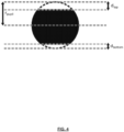
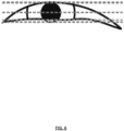
- the embodiments may also include determining, with the one or more processors, based on the image of the eye, a radius of the pupil.
- the embodiments may further include determining, with the one or more processors, based on the radius of the pupil, a total area of the pupil.
- the embodiments may additionally include determining, with the one or more processors, based on the image of the eye and the radius of the pupil, an amount of the total area of the pupil which is not obscured by either eyelid.
- the embodiments may moreover include determining, with the one or more processors, based on the amount of the total area of the pupil which is not obscured by the eyelid and the total area of the pupil, whether the eye of the user is closed.
- any detail discussed with regard to one embodiment may or may not be present in all contemplated versions of that embodiment.
- any detail discussed with regard to one embodiment may or may not be present in all contemplated versions of other embodiments discussed herein.
- the absence of discussion of any detail with regard to any embodiment herein shall be an implicit recognition that such detail may or may not be present in any version of any embodiment discussed herein.
- circuits, systems, networks, processes, and other elements in the invention may be shown as components in block diagram form in order not to obscure the embodiments in unnecessary detail.
- well-known circuits, processes, algorithms, structures, and techniques may be shown without unnecessary detail in order to avoid obscuring the embodiments.
- a process may correspond to a method, a function, a procedure, a subroutine, a subprogram, etc. When a process corresponds to a function, its termination corresponds to a return of the function to the calling function or the main function.
- machine-readable medium includes, but is not limited to transitory and non-transitory, portable or fixed storage devices, optical storage devices, wireless channels and various other mediums capable of storing, containing or carrying instruction(s) and/or data.
- a code segment or machine-executable instructions may represent a procedure, a function, a subprogram, a program, a routine, a subroutine, a module, a software package, a class, or any combination of instructions, data structures, or program statements.
- a code segment may be coupled to another code segment or a hardware circuit by passing and/or receiving information, data, arguments, parameters, or memory contents. Information, arguments, parameters, data, etc. may be passed, forwarded, or transmitted via any suitable means including memory sharing, message passing, token passing, network transmission, etc.
- embodiments of the invention may be implemented, at least in part, either manually or automatically.
- Manual or automatic implementations may be executed, or at least assisted, through the use of machines, hardware, software, firmware, middleware, microcode, hardware description languages, or any combination thereof.
- the program code or code segments to perform the necessary tasks may be stored in a machine readable medium.
- a processor(s) may perform the necessary tasks.
- the present invention generally relates to systems and methods for eye tracking, and the use thereof, in particular, to systems and methods for eye tracking in a wearable device.
- Wearable devices have risen to prominence in recent years, such devices typically contain at least one display and are commonly used in Virtual Reality (VR) or Augmented Reality (AR) applications.
- VR Virtual Reality
- AR Augmented Reality
- Eye tracking is the process of determine a person's gaze direction. This is typically done using an image sensor based eye tracking device, where an illuminator projects infrared light onto the eye of a user, and the image sensor captures an image containing a reflection of the infrared light from the eye. From the location of the reflection upon the eye, a gaze direction of the eye can be determined. Eye tracking devices come in various configurations of image sensors, illuminators, and processing structures, as would be readily understood by a person of skill in the art.
- Employing eye tracking technology in a wearable device may have certain advantages. For example, it may allow for more natural interaction in a virtual or augmented reality environment.
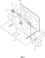
- a wearable device for wearing on a user's head.
- the wearable device may include at least one display and an eye tracking device.
- the eye tracking device may, for example, include at least one image sensor and at least one infrared illuminator, as previously discussed.
- the image sensor may be any conventional complimentary metal-oxide semiconductor (CMOS) or charge-coupled device (CCD) image sensor containing a plurality of pixels, as would be readily understood by a person of skill in the art.
- CMOS complimentary metal-oxide semiconductor
- CCD charge-coupled device
- the eye tracking device may be arranged within the wearable device so as to be in close proximity to a user's eye when the wearable device is worn by the user.
- a processing unit may be operably coupled with the image sensor(s) and illuminator(s), for processing images captured by the image sensor to determine gaze direction.
- the infrared illuminator may project infrared illumination toward the user's eye, and the image sensor captures an image of the user's eye area.
- the sensor and/or processor may then sum the value or intensity received of all pixels from the captured image (where higher values/intensity are characteristic of closed eyes), resulting in an overall sum X. This is repeated for every image captured by the image sensor. An example of such repeated monitoring is shown in the graph of FIG. 1 , which shows sum of intensity (Y-axis) versus time (X-axis).
- the Y data in FIG. 1 is a baseline, which can be adjusted according to various embodiments, and may be different for each individual user.
- One method of adjusting the baseline Y is to determine a type of low-pass filtered value (for example, a moving average filter value) for images of a particular user's eyes when open.
- the Z data in FIG. 1 is a threshold at which the eye is believed to substantially closed, which is compared to the value of X in order to determine if the user is performing a blink. If X exceeds the threshold Z, then it may be determined that the user's eye is performing a closing motion until the value of X returns below the threshold Z. In some embodiments, threshold Z may also be adjusted based on data collected during operation of the methods disclosed herein.
- the sum of pixels X may be analyzed using the following formulas to determine if a user is blinking:
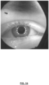
- the value of Y is set to a specific value when a predetermined glint pattern is detected, appropriate for the number of illuminators causing potential glints.
- the predetermined glint pattern indicates the number of the glints meets a predetermined threshold value and the shape of the glints is substantially circular and the locations of the glints are in a predefined region (e.g. the glints are in the vicinity of the pupil.)
- the distance between the adjacent glints may also be substantially identical.
- the glints may be aligned at two sides of the pupil respectively in a circular like pattern). See FIG. 1A for examples of the above characteristics.
- illuminators arranged in a circle are directed toward a user's eye. If an image of the eye reveals glints caused by all eight present illuminators, it can be decided that the user's eye is open. If the image reveals no glints, it can be decided that the user's eye is closed. If the image reveals between I and 7 glints caused by the illuminators, it can be decided that the user's eye is in the process of opening or closing. Depending on the embodiment, these interim conditions which occur during opening or closing may be classified as a state of open or closed to make the data binary for analytical purposes
- a method for determining openness of an eye that can accommodate eyes of different shapes and sizes, and persons whose eyes, when open, may not be as widely open as other users. These methods may be based on the fact that during a blink, no matter the person's normal eye-openness characteristics, a majority of a pupil may be obscured by the eyelid. In contrast, when a user has naturally narrow eyes, or is squinting, despite the overall eyelid position appearing similar to a blink-in-motion, a majority of their pupil will not obscured.
- the information may be used by applications capable of displaying on the wearable device, or other applications.
- applications capable of displaying on the wearable device, or other applications.
- the eye or eyes on the avatar may be updated to reflect the real life condition of the user's eye or eyes.
- the application may be running on a local wearable device containing the eye tracking device, or on a remote wearable device in communication with the user's wearable device.
- the embodiments may further include determining, for the at least portion of pixels of the image sensor of the eye tracking device, during a third time period, a third sum of intensity of the pixels.
- the embodiments may additionally include determining, with a processor, that upon the third sum exceeding a fourth sum of the first sum plus a threshold amount, that the eye of the user is closed, where the threshold amount is equal to a product of a threshold fraction and a difference between the first sum and the second sum.
- the threshold fraction may be between about 1/8 and about 1/2.
- the first predefined number may be selected from a group consisting of all integers between zero and a total number of the plurality of illuminators.
- the methods and systems may also include determining, with the at least one processor, based on the number of reflections being more than zero, but less than a total number of the plurality of illuminators, that the eye of the user is in a process of opening or closing.
- systems and methods for determining eye openness with an eye tracking device may include receiving, at one or more processors, an image of an eye of a user from an image sensor of an eye tracking device.
- the embodiments may also include determining, with the one or more processors, based on the image of the eye, a radius of the pupil.
- the embodiments may further include determining, with the one or more processors, based on the radius of the pupil, a total area of the pupil.
- the embodiments may additionally include determining, with the one or more processors, based on the image of the eye and the radius of the pupil, an amount of the total area of the pupil which is not obscured byeither eyelid.
- the embodiments may moreover include determining, with the one or more processors, based on the amount of the total area of the pupil which is not obscured by the eyelid and the total area of the pupil, whether the eye of the user is closed.
- the eye of the user when the total area of the pupil which is not obscured is greater than a remainder of the pupil, the eye of the user is open. In these or other embodiments, when the total area of the pupil which is not obscured is less than a remainder of the pupil, the eye of the user is closed.
- the systems and methods may further include determining, with the one or more processors, based on the image of the eye, that a center of the pupil is obscured by either eyelid, and determining, with the one or more processors, based on the center of the pupil being obscured by either eyelid, that the eye of the user is closed.
- a system and method for instructing a user to appropriately position a wearable device upon their head where said wearable device contains an eye tracking device.
- the wearable device may be in the form of a VR or AR headset having at least one display.
- the wearable device may include an eye tracking device having at least one image sensor and at least one infrared illuminator, where the image sensor may be arranged so as to be able to capture and image of at least a portion of a wearer's eye, and the infrared illuminator may be arranged to project infrared illumination onto a wearer's eye.
- an application is executed by a processor, causing items to be displayed on the display of the wearable device.
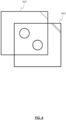
- These items may be graphical guides for a user wearing the wearable device, so as to assist the user in positioning the wearable device upon the user's head in a manner so as to allow for functional eye tracking by the eye tracking device.
- second graphical guide 820 when overlaid upon first graphical guide 810 it provides the user with a visual representation of the location of their eye or eyes relative to the lens of an image sensor imaging their eyes.
- Either or both of graphical guides 810, 820 may change color to indicate the suitability of the current position of the user's eye or eyes for eye tracking.
- the color green may be used to indicate an very correlated position, while the color red may indicate an inadequately correlated position.
- Other colors, for example orange, may be used to indicate an adequately correlated position (i.e., not perfectly correlated, but sufficient for usable eye tracking).
- the position of the wearable device may be adjusted by moving the entire unit, or the two lenses may be adjusted relative to each other. This may be performed by a mechanical means, such as rotating a knob connected to a gear to mechanically slide the two lenses closer together or further apart, or via electronic means controlling a motor or the like.
- One such system may include a wearable device and one or more processors.
- the system and/or the user may perform various methods, and/or execute various methods stored on machine readable mediums.
- one, more, or all of the processors will be disposed within the wearable device.
- one, more, or all of the processors will be disposed within the eye tracking device of the wearable device.
- one, more, or all of the processors will be disposed within a separate but communicatively coupled computing device (for example, a mobile device, a tablet, a notebook, a laptop, a desktop, or a remote/cloud computing device).
- the wearable device may include a display, at least one lens movably disposed in front of the display, and an eye tracking device including at least one illuminator and at least on image sensor.
- the display may be an LCD and/or LED display typical of VR headsets, display modules such as retinal scan displays and/or retinal projectors, and the lenses may be Fresnel and/or other lens intended to assist the wearable device in providing a three-dimensional immersive effect for the user viewing the display.
- multiple Fresnel or other lenses in series may be combined into a lens stack and employed in lieu of a single lens. While the distance between the display and the lenses may be fixed in many embodiments, the distance between the lenses and the user's eyes may be adjustable in the wearable device. Optimization of this distance may improve presentation of the display to the user such that an improved three-dimensional immersive effect is provided to the user.
- the one or more processors may be configured to receive data from the eye tracking device, and determine, based at least on the data, a first position of at least one eye of a user wearing the wearable device, where the position is relative to a second position which is fixed with respect to the at least one lens.
- data from the eye tracking device may be evaluated by the processors to determine the first position of an eye of the user.
- the eye tracking device may determine the first position of the eye of the user, and report it directly to the processor.
- the first position may be any consistently located position on a user's eye.
- the first position may represent the location of a pupil of one eye of the user.
- the first position may represent a location of a cornea spherical region of one eye of the user. Any other consistent characteristic location on a user's eye may also be used as the location of the first position.
- the first and second positions may have any one or more of three axial components.
- either position may have an X-axis position, a Y-axis position, and a Z-axis position.
- the X and Y-axes may be coplanar to the display (and the lenses disposed in front of the display), while the Z-axis may be perpendicular to the X and Y-axes (i.e., toward and away from the user as they view the display; also referred to as the lens relief direction).
- the one or more processors may also be configured to determine a distance between the first position and the second position. Because the first position is determined relative to the second position, the distance is determinable by the processor and/or eye tracking device. As noted above, both the first position and the second position may have X, Y, and Z-axes, and therefore the distance between the two positions may be determined to have vectors in each of these directions.
- methods of various embodiments may cause information to be presented to the user indicating that the one or more lens should be moved to a more optimal position.
- This information may be audibly, visually, or tactilely presented.
- the method may cause content to be presented on the display which informs the user that the lenses are too close, or too far from the user's eye.
- the content may also inform the user how to manually cause the lens to be repositioned in light thereof.
- the user wearable device may have a control on it to mechanically or electromechanically move the lens as described.
- the content displayed may instruct the user on the location and particulars of such control.
- audible information may be presented to the user via a speaker, etc.
- tactile feedback be presented to the user, perhaps by intermittent/pulsed operation of an automatic electro-mechanical movement system which can reposition the lens without manual user input.
- an electro-mechanical movement system may be provided to automatically reposition the lens with respect to the user's eyes based on the distance determination made earlier (and thereafter compared to the threshold values). This automatic repositioning may occur upon completion of the comparison of the determined distance with the threshold(s). As with the determination of the distance and comparison to the thresholds, this process may repeat automatically over time, and/or at the direction of the user (by instruction from the user to the processors, etc.).
- automatic electro-mechanical movements systems may also be present to move each of two lenses in the wearable device closer to, or away from, each other, potentially in the x-axis direction (i.e., left-right with respect to the user). Such automatic movement systems may be employed to implement other embodiments of the invention such as those discussed above to account for changes needed to eye-to-eye or inter-pupillary distance.
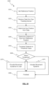
- FIG. 10 is a block diagram of a method 1000 as described for adjusting the location of lenses in a wearable device.
- a reference position is determined or otherwise identified, perhaps as pre-defined.
- data is received from the eye tracking device.
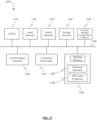
- FIG. 11 is a block diagram illustrating a specialized computer system 1100 in which embodiments of the present invention may be implemented.
- This example illustrates specialized computer system 1100 such as may be used, in whole, in part, or with various modifications, to provide the functions of display 905, eye tracking devices 915, processors 930, movement systems 935, 940, and/or other components of the invention such as those discussed above.
- various functions of processors 930 may be controlled by specialized computer system 1100, including, merely by way of example, determining distances from eye features to a reference point, comparing distances to predefined thresholds, etc.
- Specialized computer system 1100 is shown comprising hardware elements that may be electrically coupled via a bus 1190.
- the hardware elements may include one or more central processing units 1110, one or more input devices 1120 (e.g., a mouse, a keyboard, a touchpad, an eye tracking device, etc.), and one or more output devices 1130 (e.g., a display device, a printer, etc.).
- Specialized computer system 1100 may also include one or more storage device 1140.
- storage device(s) 1140 may be disk drives, optical storage devices, solid-state storage device such as a random access memory (“RAM”) and/or a read-only memory (“ROM”), which can be programmable, flash-updateable and/or the like.
- RAM random access memory
- ROM read-only memory
- Specialized computer system 1100 may additionally include a computer-readable storage media reader 1150, a communications system 1160 (e.g., a modem, a network card (wireless or wired), an infra-red communication device, Bluetooth TM device, cellular communication device, etc.), and working memory 1180, which may include RAM and ROM devices as described above.
- specialized computer system 1100 may also include a processing acceleration unit 1170, which can include a digital signal processor, a special-purpose processor and/or the like.
- Computer-readable storage media reader 1150 can further be connected to a computer-readable storage medium, together (and, optionally, in combination with storage device(s) 1140) comprehensively representing remote, local, fixed, and/or removable storage devices plus storage media for temporarily and/or more permanently containing computer-readable information.
- Communications system 1160 may permit data to be exchanged with a network, system, computer and/or other component described above.
- Specialized computer system 1100 may also comprise software elements, shown as being currently located within a working memory 1180, including an operating system 1184 and/or other code 1188. It should be appreciated that alternate embodiments of specialized computer system 1100 may have numerous variations from that described above. For example, customized hardware might also be used and/or particular elements might be implemented in hardware, software (including portable software, such as applets), or both. Furthermore, connection to other computing devices such as network input/output and data acquisition devices may also occur.
- Software of specialized computer system 1100 may include code 1188 for implementing any or all of the function of the various elements of the architecture as described herein.
- software stored on and/or executed by a specialized computer system such as specialized computer system 1100, can provide the functions of display 905, eye tracking devices 915, movement systems 935, 940, processors 930, and/or other components of the invention such as those discussed above. Methods implementable by software on some of these components have been discussed above in more detail.
Landscapes
- Health & Medical Sciences (AREA)
- Life Sciences & Earth Sciences (AREA)
- Engineering & Computer Science (AREA)
- Physics & Mathematics (AREA)
- General Health & Medical Sciences (AREA)
- Biophysics (AREA)
- Heart & Thoracic Surgery (AREA)
- Surgery (AREA)
- Public Health (AREA)
- Molecular Biology (AREA)
- Medical Informatics (AREA)
- Veterinary Medicine (AREA)
- Animal Behavior & Ethology (AREA)
- Biomedical Technology (AREA)
- Ophthalmology & Optometry (AREA)
- General Physics & Mathematics (AREA)
- Pathology (AREA)
- Theoretical Computer Science (AREA)
- Human Computer Interaction (AREA)
- Dentistry (AREA)
- Oral & Maxillofacial Surgery (AREA)
- General Engineering & Computer Science (AREA)
- Optics & Photonics (AREA)
- Computer Vision & Pattern Recognition (AREA)
- Physiology (AREA)
- Psychology (AREA)
- Hospice & Palliative Care (AREA)
- Psychiatry (AREA)
- Educational Technology (AREA)
- Social Psychology (AREA)
- Developmental Disabilities (AREA)
- Child & Adolescent Psychology (AREA)
- Multimedia (AREA)
- Nuclear Medicine, Radiotherapy & Molecular Imaging (AREA)
- Radiology & Medical Imaging (AREA)
- Eye Examination Apparatus (AREA)
- User Interface Of Digital Computer (AREA)
Claims (12)
- Verfahren zum Bestimmen der Augenöffnung mit einer Augenverfolgungsvorrichtung, wobei das Verfahren umfasst:Empfangen, an einem oder mehreren Prozessoren, eines Bilds eines Auges eines Benutzers von einem Bildsensor einer Augenverfolgungsvorrichtung;Bestimmen, mit dem einen oder den mehreren Prozessoren, basierend auf dem Bild des Auges, eines Radius der Pupille;Bestimmen, mit dem einen oder den mehreren Prozessoren, basierend auf dem Radius der Pupille, einer Gesamtfläche der Pupille;Bestimmen, mit dem einen oder den mehreren Prozessoren, basierend auf dem Bild des Auges und dem Radius der Pupille, eines Anteils der Gesamtfläche der Pupille, die durch kein Augenlid verdeckt ist; undBestimmen, mit dem einen oder den mehreren Prozessoren, basierend auf dem Anteil der Gesamtfläche der Pupille, die nicht durch das Augenlid verdeckt ist, und der Gesamtfläche der Pupille, ob das Auge des Benutzers geschlossen ist.
- Verfahren zum Bestimmen der Augenöffnung mit einer Augenverfolgungsvorrichtung nach Anspruch 1, wobei:
wenn die Gesamtfläche der Pupille, die nicht verdeckt ist, größer als ein Rest der Pupille ist, das Auge des Benutzers geöffnet ist. - Verfahren zum Bestimmen der Augenöffnung mit einer Augenverfolgungsvorrichtung nach Anspruch 1, wobei:
wenn die Gesamtfläche der Pupille, die nicht verdeckt ist, geringer als ein Rest der Pupille ist, das Auge des Benutzers geschlossen ist. - Verfahren zum Bestimmen der Augenöffnung mit einer Augenverfolgungsvorrichtung nach Anspruch 1, wobei das Verfahren ferner umfasst:Bestimmen, mit dem einen oder den mehreren Prozessoren, basierend auf dem Bild des Auges, dass eine Mitte der Pupille durch ein beliebiges der Augenlider verdeckt ist; undBestimmen, mit dem einen oder den mehreren Prozessoren, basierend darauf, dass die Mitte der Pupille durch ein beliebiges Augenlid verdeckt ist, dass das Auge des Benutzers geschlossen ist.
- Verfahren zum Bestimmen der Augenöffnung mit einer Augenverfolgungsvorrichtung nach Anspruch 1, wobei das Verfahren ferner umfasst:Bestimmen, mit dem einen oder den mehreren Prozessoren, basierend auf dem Bild des Auges, einer maximalen Öffnung zwischen den Augenlidern im Laufe der Zeit; undBestimmen, mit dem einen oder den mehreren Prozessoren, ob das Auge des Benutzers geschlossen ist, basierend auf der maximalen Öffnung im Laufe der Zeit.
- Verfahren zum Bestimmen der Augenöffnung mit einer Augenverfolgungsvorrichtung nach Anspruch 5, wobei das Bestimmen, ob das Auge des Benutzers geschlossen ist, basierend auf der maximalen Öffnung im Laufe der Zeit, umfasst:
Bestimmen, basierend auf dem Bild des Auges, dass eine Öffnung des Auges im Laufe der Zeit geringer als ein vordefinierter Anteil der maximalen Öffnung ist. - Augenverfolgungsvorrichtung, umfassend einen Bildsensor, der auf ein Auge eines Benutzers gerichtet ist, wobei die Augenverfolgungsvorrichtung konfiguriert ist zum:Empfangen, an einem oder mehreren Prozessoren, eines Bilds des Auges des Benutzers von dem Bildsensor der Augenverfolgungsvorrichtung;Bestimmen, mit dem einen oder den mehreren Prozessoren, basierend auf dem Bild des Auges, eines Radius der Pupille;Bestimmen, mit dem einen oder den mehreren Prozessoren, basierend auf dem Radius der Pupille, einer Gesamtfläche der Pupille;Bestimmen, mit dem einen oder den mehreren Prozessoren, basierend auf dem Bild des Auges und dem Radius der Pupille, eines Anteils der Gesamtfläche der Pupille, die durch kein Augenlid verdeckt ist; undBestimmen, mit dem einen oder den mehreren Prozessoren, basierend auf dem Anteil der Gesamtfläche der Pupille, die nicht durch das Augenlid verdeckt ist, und der Gesamtfläche der Pupille, ob das Auge des Benutzers geschlossen ist.
- Augenverfolgungsvorrichtung nach Anspruch 7, das ferner konfiguriert ist zum:
Bestimmen, wenn die Gesamtfläche der Pupille, die nicht verdeckt ist, größer als ein Rest der Pupille ist, dass das Auge des Benutzers geöffnet ist. - Augenverfolgungsvorrichtung nach Anspruch 7, das ferner konfiguriert ist zum:
Bestimmen, wenn die Gesamtfläche der Pupille, die nicht verdeckt ist, geringer als ein Rest der Pupille ist, dass das Auge des Benutzers geschlossen ist. - Augenverfolgungsvorrichtung nach Anspruch 7, das ferner konfiguriert ist zum:Bestimmen, mit dem einen oder den mehreren Prozessoren, basierend auf dem Bild des Auges, dass eine Mitte der Pupille durch ein beliebiges der Augenlider verdeckt ist; undBestimmen, mit dem einen oder den mehreren Prozessoren, basierend darauf, dass die Mitte der Pupille durch ein beliebiges Augenlid verdeckt ist, dass das Auge des Benutzers geschlossen ist.
- Augenverfolgungsvorrichtung nach Anspruch 7, das ferner konfiguriert ist zum:Bestimmen, mit dem einen oder den mehreren Prozessoren, basierend auf dem Bild des Auges, einer maximalen Öffnung zwischen den Augenlidern im Laufe der Zeit; undBestimmen, mit dem einen oder den mehreren Prozessoren, ob das Auge des Benutzers geschlossen ist, basierend auf der maximalen Öffnung im Laufe der Zeit.
- Augenverfolgungsvorrichtung nach Anspruch 11, wobei die Augenverfolgungsvorrichtung konfiguriert ist, um basierend auf der maximalen Öffnung im Laufe der Zeit zu bestimmen, ob das Auge des Benutzers geschlossen ist, durch:
Bestimmen, basierend auf dem Bild des Auges, dass eine Öffnung des Auges im Laufe der Zeit geringer als ein vordefinierter Anteil der maximalen Öffnung ist.
Applications Claiming Priority (3)
| Application Number | Priority Date | Filing Date | Title |
|---|---|---|---|
| US201762464235P | 2017-02-27 | 2017-02-27 | |
| PCT/US2018/017612 WO2018156366A1 (en) | 2017-02-27 | 2018-02-09 | Determining eye openness with an eye tracking device |
| EP18707481.0A EP3641624B1 (de) | 2017-02-27 | 2018-02-09 | Bestimmung der augenöffnung mit einer augenverfolgungsvorrichtung |
Related Parent Applications (2)
| Application Number | Title | Priority Date | Filing Date |
|---|---|---|---|
| EP18707481.0A Division-Into EP3641624B1 (de) | 2017-02-27 | 2018-02-09 | Bestimmung der augenöffnung mit einer augenverfolgungsvorrichtung |
| EP18707481.0A Division EP3641624B1 (de) | 2017-02-27 | 2018-02-09 | Bestimmung der augenöffnung mit einer augenverfolgungsvorrichtung |
Publications (2)
| Publication Number | Publication Date |
|---|---|
| EP4014835A1 EP4014835A1 (de) | 2022-06-22 |
| EP4014835B1 true EP4014835B1 (de) | 2024-07-24 |
Family
ID=61283321
Family Applications (3)
| Application Number | Title | Priority Date | Filing Date |
|---|---|---|---|
| EP22154883.7A Active EP4014835B1 (de) | 2017-02-27 | 2018-02-09 | Bestimmung der augenöffnung mit einer augenverfolgungsvorrichtung |
| EP22154882.9A Withdrawn EP4016489A1 (de) | 2017-02-27 | 2018-02-09 | Bestimmung der augenöffnung mit einer augenverfolgungsvorrichtung |
| EP18707481.0A Active EP3641624B1 (de) | 2017-02-27 | 2018-02-09 | Bestimmung der augenöffnung mit einer augenverfolgungsvorrichtung |
Family Applications After (2)
| Application Number | Title | Priority Date | Filing Date |
|---|---|---|---|
| EP22154882.9A Withdrawn EP4016489A1 (de) | 2017-02-27 | 2018-02-09 | Bestimmung der augenöffnung mit einer augenverfolgungsvorrichtung |
| EP18707481.0A Active EP3641624B1 (de) | 2017-02-27 | 2018-02-09 | Bestimmung der augenöffnung mit einer augenverfolgungsvorrichtung |
Country Status (5)
| Country | Link |
|---|---|
| US (3) | US10642028B2 (de) |
| EP (3) | EP4014835B1 (de) |
| CN (2) | CN110352033B (de) |
| ES (2) | ES2922136T3 (de) |
| WO (1) | WO2018156366A1 (de) |
Families Citing this family (17)
| Publication number | Priority date | Publication date | Assignee | Title |
|---|---|---|---|---|
| US10642028B2 (en) | 2017-02-27 | 2020-05-05 | Tobii Ab | Lens position adjustment in a wearable device |
| US10810773B2 (en) * | 2017-06-14 | 2020-10-20 | Dell Products, L.P. | Headset display control based upon a user's pupil state |
| US20210000341A1 (en) * | 2018-03-09 | 2021-01-07 | Children's Hospital & Research Center At Oakland | Method of detecting and/or predicting seizures |
| US11966055B2 (en) * | 2018-07-19 | 2024-04-23 | Magic Leap, Inc. | Content interaction driven by eye metrics |
| US11402901B2 (en) * | 2019-03-22 | 2022-08-02 | Hewlett-Packard Development Company, L.P. | Detecting eye measurements |
| WO2020236827A1 (en) | 2019-05-20 | 2020-11-26 | Magic Leap, Inc. | Systems and techniques for estimating eye pose |
| EP4162343A4 (de) | 2020-06-05 | 2024-06-12 | Magic Leap, Inc. | Verbesserte augenverfolgungstechniken auf der basis von neuronaler netzwerkanalyse von bildern |
| CN113815623B (zh) * | 2020-06-11 | 2023-08-08 | 广州汽车集团股份有限公司 | 一种视觉追踪人眼注视点的方法、车辆预警方法及装置 |
| US11998275B2 (en) | 2020-07-15 | 2024-06-04 | Magic Leap, Inc. | Eye tracking using aspheric cornea model |
| CN112401887B (zh) * | 2020-11-10 | 2023-12-12 | 恒大新能源汽车投资控股集团有限公司 | 一种驾驶员注意力监测方法、装置及电子设备 |
| US12224049B2 (en) | 2020-12-09 | 2025-02-11 | Eysz, Inc. | Systems and methods for monitoring and managing neurological diseases and conditions |
| US11503998B1 (en) | 2021-05-05 | 2022-11-22 | Innodem Neurosciences | Method and a system for detection of eye gaze-pattern abnormalities and related neurological diseases |
| CN115670368A (zh) * | 2021-07-23 | 2023-02-03 | 京东方科技集团股份有限公司 | 一种成像调整装置及方法、可穿戴设备、存储介质 |
| SE2250299A1 (en) | 2022-03-04 | 2023-09-05 | Tobii Ab | Eye openness |
| US12204689B2 (en) | 2022-09-27 | 2025-01-21 | Tobii Dynavox Ab | Method, system, and computer program product for drawing and fine-tuned motor controls |
| TWI873948B (zh) * | 2023-10-31 | 2025-02-21 | 緯創資通股份有限公司 | 人眼開闔偵測裝置及其人眼開闔偵測方法 |
| JP2025088543A (ja) * | 2023-11-30 | 2025-06-11 | 株式会社Qdレーザ | 画像投影装置 |
Family Cites Families (39)
| Publication number | Priority date | Publication date | Assignee | Title |
|---|---|---|---|---|
| US7415126B2 (en) * | 1992-05-05 | 2008-08-19 | Automotive Technologies International Inc. | Occupant sensing system |
| US6702809B1 (en) * | 1989-02-06 | 2004-03-09 | Visx, Inc. | System for detecting, measuring and compensating for lateral movements of a target |
| JP3563459B2 (ja) * | 1994-10-31 | 2004-09-08 | 大正製薬株式会社 | 瞬き検出システム |
| US6542081B2 (en) * | 1996-08-19 | 2003-04-01 | William C. Torch | System and method for monitoring eye movement |
| US6299307B1 (en) * | 1997-10-10 | 2001-10-09 | Visx, Incorporated | Eye tracking device for laser eye surgery using corneal margin detection |
| AUPP048097A0 (en) * | 1997-11-21 | 1997-12-18 | Xenotech Research Pty Ltd | Eye tracking apparatus |
| US6087941A (en) * | 1998-09-01 | 2000-07-11 | Ferraz; Mark | Warning device for alerting a person falling asleep |
| JP3768735B2 (ja) * | 1999-07-07 | 2006-04-19 | 三菱電機株式会社 | 顔画像処理装置 |
| US6322216B1 (en) | 1999-10-07 | 2001-11-27 | Visx, Inc | Two camera off-axis eye tracker for laser eye surgery |
| JP3769442B2 (ja) * | 2000-02-15 | 2006-04-26 | ナイルス株式会社 | 眼の状態検出装置 |
| US6980691B2 (en) * | 2001-07-05 | 2005-12-27 | Corel Corporation | Correction of “red-eye” effects in images |
| US6943754B2 (en) * | 2002-09-27 | 2005-09-13 | The Boeing Company | Gaze tracking system, eye-tracking assembly and an associated method of calibration |
| JP2004329879A (ja) * | 2003-02-07 | 2004-11-25 | Nippon Syst Design Kk | 眼球検査装置及び眼球検査方法 |
| US7347551B2 (en) | 2003-02-13 | 2008-03-25 | Fergason Patent Properties, Llc | Optical system for monitoring eye movement |
| US8064647B2 (en) * | 2006-03-03 | 2011-11-22 | Honeywell International Inc. | System for iris detection tracking and recognition at a distance |
| WO2005046465A1 (en) | 2003-11-14 | 2005-05-26 | Queen's University At Kingston | Method and apparatus for calibration-free eye tracking |
| US7253739B2 (en) * | 2005-03-10 | 2007-08-07 | Delphi Technologies, Inc. | System and method for determining eye closure state |
| JP2007011666A (ja) * | 2005-06-30 | 2007-01-18 | Matsushita Electric Ind Co Ltd | 認証装置および認証方法 |
| JP4899059B2 (ja) * | 2007-03-30 | 2012-03-21 | 国立大学法人静岡大学 | 眠気検知装置 |
| US8189879B2 (en) * | 2008-02-14 | 2012-05-29 | Iristrac, Llc | System and method for animal identification using IRIS images |
| WO2010011785A1 (en) * | 2008-07-23 | 2010-01-28 | Indiana University Research & Technology Corporation | System and method for a non-cooperative iris image acquisition system |
| JP5078815B2 (ja) * | 2008-09-12 | 2012-11-21 | 株式会社豊田中央研究所 | 開眼度推定装置 |
| TWI398796B (zh) * | 2009-03-27 | 2013-06-11 | Utechzone Co Ltd | Pupil tracking methods and systems, and correction methods and correction modules for pupil tracking |
| EP2237237B1 (de) * | 2009-03-30 | 2013-03-20 | Tobii Technology AB | Augenschließungserkennung mit strukturierter Beleuchtung |
| US8594374B1 (en) * | 2011-03-30 | 2013-11-26 | Amazon Technologies, Inc. | Secure device unlock with gaze calibration |
| US8824779B1 (en) * | 2011-12-20 | 2014-09-02 | Christopher Charles Smyth | Apparatus and method for determining eye gaze from stereo-optic views |
| US9025830B2 (en) | 2012-01-20 | 2015-05-05 | Cyberlink Corp. | Liveness detection system based on face behavior |
| US8437513B1 (en) | 2012-08-10 | 2013-05-07 | EyeVerify LLC | Spoof detection for biometric authentication |
| CN103049740B (zh) * | 2012-12-13 | 2016-08-03 | 杜鹢 | 基于视频图像的疲劳状态检测方法及装置 |
| US20140375540A1 (en) | 2013-06-24 | 2014-12-25 | Nathan Ackerman | System for optimal eye fit of headset display device |
| US20140375541A1 (en) * | 2013-06-25 | 2014-12-25 | David Nister | Eye tracking via depth camera |
| WO2015094191A1 (en) * | 2013-12-17 | 2015-06-25 | Intel Corporation | Controlling vision correction using eye tracking and depth detection |
| US9361519B2 (en) * | 2014-03-28 | 2016-06-07 | Intel Corporation | Computational array camera with dynamic illumination for eye tracking |
| CN105224285A (zh) * | 2014-05-27 | 2016-01-06 | 北京三星通信技术研究有限公司 | 眼睛开闭状态检测装置和方法 |
| CN104391567B (zh) * | 2014-09-30 | 2017-10-31 | 深圳市魔眼科技有限公司 | 一种基于人眼跟踪的三维全息虚拟物体显示控制方法 |
| US20160140390A1 (en) | 2014-11-13 | 2016-05-19 | Intel Corporation | Liveness detection using progressive eyelid tracking |
| US9870049B2 (en) * | 2015-07-31 | 2018-01-16 | Google Llc | Reflective lenses to auto-calibrate a wearable system |
| US10401625B2 (en) * | 2015-12-28 | 2019-09-03 | Facebook Technologies, Llc | Determining interpupillary distance and eye relief of a user wearing a head-mounted display |
| US10642028B2 (en) | 2017-02-27 | 2020-05-05 | Tobii Ab | Lens position adjustment in a wearable device |
-
2018
- 2018-02-09 US US15/893,014 patent/US10642028B2/en active Active
- 2018-02-09 EP EP22154883.7A patent/EP4014835B1/de active Active
- 2018-02-09 ES ES18707481T patent/ES2922136T3/es active Active
- 2018-02-09 CN CN201880013360.1A patent/CN110352033B/zh active Active
- 2018-02-09 ES ES22154883T patent/ES2989012T3/es active Active
- 2018-02-09 CN CN202310509108.2A patent/CN116687336A/zh active Pending
- 2018-02-09 US US15/893,340 patent/US10394019B2/en active Active
- 2018-02-09 EP EP22154882.9A patent/EP4016489A1/de not_active Withdrawn
- 2018-02-09 EP EP18707481.0A patent/EP3641624B1/de active Active
- 2018-02-09 WO PCT/US2018/017612 patent/WO2018156366A1/en not_active Ceased
-
2019
- 2019-06-24 US US16/449,828 patent/US10852531B2/en active Active
Also Published As
| Publication number | Publication date |
|---|---|
| CN110352033A (zh) | 2019-10-18 |
| US20180247119A1 (en) | 2018-08-30 |
| EP3641624B1 (de) | 2022-06-01 |
| CN116687336A (zh) | 2023-09-05 |
| WO2018156366A1 (en) | 2018-08-30 |
| US10394019B2 (en) | 2019-08-27 |
| EP4016489A1 (de) | 2022-06-22 |
| EP3641624A1 (de) | 2020-04-29 |
| US20180246320A1 (en) | 2018-08-30 |
| ES2922136T3 (es) | 2022-09-08 |
| CN110352033B (zh) | 2023-04-28 |
| ES2989012T3 (es) | 2024-11-25 |
| US10852531B2 (en) | 2020-12-01 |
| EP4014835A1 (de) | 2022-06-22 |
| US10642028B2 (en) | 2020-05-05 |
| US20200026068A1 (en) | 2020-01-23 |
Similar Documents
| Publication | Publication Date | Title |
|---|---|---|
| EP4014835B1 (de) | Bestimmung der augenöffnung mit einer augenverfolgungsvorrichtung | |
| EP3453316B1 (de) | Augenverfolgung unter verwendung der mittelposition des augapfels | |
| EP3195595B1 (de) | Technologien zur einstellung einer perspektive eines aufgenommenen bildes zur anzeige | |
| CN109803574B (zh) | 具有显示器、透镜、照明器和图像传感器的可穿戴设备 | |
| US20180103193A1 (en) | Image capture systems, devices, and methods that autofocus based on eye-tracking | |
| US9946341B2 (en) | Information observation method and information observation device | |
| US11402901B2 (en) | Detecting eye measurements | |
| US10725540B2 (en) | Augmented reality speed reading | |
| EP3158921A1 (de) | Sichtlinienerkennungssystem und -vorrichtung | |
| US20210378509A1 (en) | Pupil assessment using modulated on-axis illumination | |
| CN112445339A (zh) | 基于注视和扫视的图形操纵 | |
| US11231591B2 (en) | Information processing apparatus, information processing method, and program | |
| EP4312205A1 (de) | Steuerungsvorrichtung, brillenartige informationsanzeigevorrichtung, steuerungsverfahren und steuerungsprogramm | |
| WO2020264101A1 (en) | Systems and methods for characterizing joint attention during real world interaction | |
| CN113132642A (zh) | 图像显示的方法及装置、电子设备 | |
| EP4400947B1 (de) | Erkennung von hochaufmerksamkeitsmerkmalen | |
| KR102337908B1 (ko) | 작업 보조 방법 및 장치 | |
| Borsato et al. | xSDL: stroboscopic differential lighting eye tracker with extended temporal support |
Legal Events
| Date | Code | Title | Description |
|---|---|---|---|
| PUAI | Public reference made under article 153(3) epc to a published international application that has entered the european phase |
Free format text: ORIGINAL CODE: 0009012 |
|
| STAA | Information on the status of an ep patent application or granted ep patent |
Free format text: STATUS: THE APPLICATION HAS BEEN PUBLISHED |
|
| AC | Divisional application: reference to earlier application |
Ref document number: 3641624 Country of ref document: EP Kind code of ref document: P |
|
| AK | Designated contracting states |
Kind code of ref document: A1 Designated state(s): AL AT BE BG CH CY CZ DE DK EE ES FI FR GB GR HR HU IE IS IT LI LT LU LV MC MK MT NL NO PL PT RO RS SE SI SK SM TR |
|
| STAA | Information on the status of an ep patent application or granted ep patent |
Free format text: STATUS: REQUEST FOR EXAMINATION WAS MADE |
|
| 17P | Request for examination filed |
Effective date: 20221214 |
|
| RBV | Designated contracting states (corrected) |
Designated state(s): AL AT BE BG CH CY CZ DE DK EE ES FI FR GB GR HR HU IE IS IT LI LT LU LV MC MK MT NL NO PL PT RO RS SE SI SK SM TR |
|
| GRAP | Despatch of communication of intention to grant a patent |
Free format text: ORIGINAL CODE: EPIDOSNIGR1 |
|
| STAA | Information on the status of an ep patent application or granted ep patent |
Free format text: STATUS: GRANT OF PATENT IS INTENDED |
|
| INTG | Intention to grant announced |
Effective date: 20240227 |
|
| GRAS | Grant fee paid |
Free format text: ORIGINAL CODE: EPIDOSNIGR3 |
|
| GRAA | (expected) grant |
Free format text: ORIGINAL CODE: 0009210 |
|
| STAA | Information on the status of an ep patent application or granted ep patent |
Free format text: STATUS: THE PATENT HAS BEEN GRANTED |
|
| P01 | Opt-out of the competence of the unified patent court (upc) registered |
Free format text: CASE NUMBER: APP_33812/2024 Effective date: 20240606 |
|
| AC | Divisional application: reference to earlier application |
Ref document number: 3641624 Country of ref document: EP Kind code of ref document: P |
|
| AK | Designated contracting states |
Kind code of ref document: B1 Designated state(s): AL AT BE BG CH CY CZ DE DK EE ES FI FR GB GR HR HU IE IS IT LI LT LU LV MC MK MT NL NO PL PT RO RS SE SI SK SM TR |
|
| REG | Reference to a national code |
Ref country code: GB Ref legal event code: FG4D |
|
| REG | Reference to a national code |
Ref country code: CH Ref legal event code: EP |
|
| REG | Reference to a national code |
Ref country code: IE Ref legal event code: FG4D Ref country code: DE Ref legal event code: R096 Ref document number: 602018072355 Country of ref document: DE |
|
| REG | Reference to a national code |
Ref country code: LT Ref legal event code: MG9D |
|
| REG | Reference to a national code |
Ref country code: ES Ref legal event code: FG2A Ref document number: 2989012 Country of ref document: ES Kind code of ref document: T3 Effective date: 20241125 |
|
| REG | Reference to a national code |
Ref country code: NL Ref legal event code: MP Effective date: 20240724 |
|
| PG25 | Lapsed in a contracting state [announced via postgrant information from national office to epo] |
Ref country code: PT Free format text: LAPSE BECAUSE OF FAILURE TO SUBMIT A TRANSLATION OF THE DESCRIPTION OR TO PAY THE FEE WITHIN THE PRESCRIBED TIME-LIMIT Effective date: 20241125 |
|
| REG | Reference to a national code |
Ref country code: AT Ref legal event code: MK05 Ref document number: 1705488 Country of ref document: AT Kind code of ref document: T Effective date: 20240724 |
|
| PG25 | Lapsed in a contracting state [announced via postgrant information from national office to epo] |
Ref country code: NL Free format text: LAPSE BECAUSE OF FAILURE TO SUBMIT A TRANSLATION OF THE DESCRIPTION OR TO PAY THE FEE WITHIN THE PRESCRIBED TIME-LIMIT Effective date: 20240724 |
|
| PG25 | Lapsed in a contracting state [announced via postgrant information from national office to epo] |
Ref country code: PT Free format text: LAPSE BECAUSE OF FAILURE TO SUBMIT A TRANSLATION OF THE DESCRIPTION OR TO PAY THE FEE WITHIN THE PRESCRIBED TIME-LIMIT Effective date: 20241125 Ref country code: NL Free format text: LAPSE BECAUSE OF FAILURE TO SUBMIT A TRANSLATION OF THE DESCRIPTION OR TO PAY THE FEE WITHIN THE PRESCRIBED TIME-LIMIT Effective date: 20240724 |
|
| PG25 | Lapsed in a contracting state [announced via postgrant information from national office to epo] |
Ref country code: NO Free format text: LAPSE BECAUSE OF FAILURE TO SUBMIT A TRANSLATION OF THE DESCRIPTION OR TO PAY THE FEE WITHIN THE PRESCRIBED TIME-LIMIT Effective date: 20241024 |
|
| PG25 | Lapsed in a contracting state [announced via postgrant information from national office to epo] |
Ref country code: PL Free format text: LAPSE BECAUSE OF FAILURE TO SUBMIT A TRANSLATION OF THE DESCRIPTION OR TO PAY THE FEE WITHIN THE PRESCRIBED TIME-LIMIT Effective date: 20240724 Ref country code: FI Free format text: LAPSE BECAUSE OF FAILURE TO SUBMIT A TRANSLATION OF THE DESCRIPTION OR TO PAY THE FEE WITHIN THE PRESCRIBED TIME-LIMIT Effective date: 20240724 Ref country code: GR Free format text: LAPSE BECAUSE OF FAILURE TO SUBMIT A TRANSLATION OF THE DESCRIPTION OR TO PAY THE FEE WITHIN THE PRESCRIBED TIME-LIMIT Effective date: 20241025 |
|
| PG25 | Lapsed in a contracting state [announced via postgrant information from national office to epo] |
Ref country code: BG Free format text: LAPSE BECAUSE OF FAILURE TO SUBMIT A TRANSLATION OF THE DESCRIPTION OR TO PAY THE FEE WITHIN THE PRESCRIBED TIME-LIMIT Effective date: 20240724 |
|
| PG25 | Lapsed in a contracting state [announced via postgrant information from national office to epo] |
Ref country code: LV Free format text: LAPSE BECAUSE OF FAILURE TO SUBMIT A TRANSLATION OF THE DESCRIPTION OR TO PAY THE FEE WITHIN THE PRESCRIBED TIME-LIMIT Effective date: 20240724 |
|
| PG25 | Lapsed in a contracting state [announced via postgrant information from national office to epo] |
Ref country code: AT Free format text: LAPSE BECAUSE OF FAILURE TO SUBMIT A TRANSLATION OF THE DESCRIPTION OR TO PAY THE FEE WITHIN THE PRESCRIBED TIME-LIMIT Effective date: 20240724 Ref country code: IS Free format text: LAPSE BECAUSE OF FAILURE TO SUBMIT A TRANSLATION OF THE DESCRIPTION OR TO PAY THE FEE WITHIN THE PRESCRIBED TIME-LIMIT Effective date: 20241124 |
|
| PG25 | Lapsed in a contracting state [announced via postgrant information from national office to epo] |
Ref country code: HR Free format text: LAPSE BECAUSE OF FAILURE TO SUBMIT A TRANSLATION OF THE DESCRIPTION OR TO PAY THE FEE WITHIN THE PRESCRIBED TIME-LIMIT Effective date: 20240724 |
|
| PG25 | Lapsed in a contracting state [announced via postgrant information from national office to epo] |
Ref country code: PL Free format text: LAPSE BECAUSE OF FAILURE TO SUBMIT A TRANSLATION OF THE DESCRIPTION OR TO PAY THE FEE WITHIN THE PRESCRIBED TIME-LIMIT Effective date: 20240724 Ref country code: NO Free format text: LAPSE BECAUSE OF FAILURE TO SUBMIT A TRANSLATION OF THE DESCRIPTION OR TO PAY THE FEE WITHIN THE PRESCRIBED TIME-LIMIT Effective date: 20241024 Ref country code: LV Free format text: LAPSE BECAUSE OF FAILURE TO SUBMIT A TRANSLATION OF THE DESCRIPTION OR TO PAY THE FEE WITHIN THE PRESCRIBED TIME-LIMIT Effective date: 20240724 Ref country code: IS Free format text: LAPSE BECAUSE OF FAILURE TO SUBMIT A TRANSLATION OF THE DESCRIPTION OR TO PAY THE FEE WITHIN THE PRESCRIBED TIME-LIMIT Effective date: 20241124 Ref country code: HR Free format text: LAPSE BECAUSE OF FAILURE TO SUBMIT A TRANSLATION OF THE DESCRIPTION OR TO PAY THE FEE WITHIN THE PRESCRIBED TIME-LIMIT Effective date: 20240724 Ref country code: GR Free format text: LAPSE BECAUSE OF FAILURE TO SUBMIT A TRANSLATION OF THE DESCRIPTION OR TO PAY THE FEE WITHIN THE PRESCRIBED TIME-LIMIT Effective date: 20241025 Ref country code: FI Free format text: LAPSE BECAUSE OF FAILURE TO SUBMIT A TRANSLATION OF THE DESCRIPTION OR TO PAY THE FEE WITHIN THE PRESCRIBED TIME-LIMIT Effective date: 20240724 Ref country code: BG Free format text: LAPSE BECAUSE OF FAILURE TO SUBMIT A TRANSLATION OF THE DESCRIPTION OR TO PAY THE FEE WITHIN THE PRESCRIBED TIME-LIMIT Effective date: 20240724 Ref country code: AT Free format text: LAPSE BECAUSE OF FAILURE TO SUBMIT A TRANSLATION OF THE DESCRIPTION OR TO PAY THE FEE WITHIN THE PRESCRIBED TIME-LIMIT Effective date: 20240724 |
|
| PGFP | Annual fee paid to national office [announced via postgrant information from national office to epo] |
Ref country code: DE Payment date: 20250221 Year of fee payment: 8 |
|
| PG25 | Lapsed in a contracting state [announced via postgrant information from national office to epo] |
Ref country code: RO Free format text: LAPSE BECAUSE OF FAILURE TO SUBMIT A TRANSLATION OF THE DESCRIPTION OR TO PAY THE FEE WITHIN THE PRESCRIBED TIME-LIMIT Effective date: 20240724 Ref country code: SM Free format text: LAPSE BECAUSE OF FAILURE TO SUBMIT A TRANSLATION OF THE DESCRIPTION OR TO PAY THE FEE WITHIN THE PRESCRIBED TIME-LIMIT Effective date: 20240724 Ref country code: DK Free format text: LAPSE BECAUSE OF FAILURE TO SUBMIT A TRANSLATION OF THE DESCRIPTION OR TO PAY THE FEE WITHIN THE PRESCRIBED TIME-LIMIT Effective date: 20240724 |
|
| PGFP | Annual fee paid to national office [announced via postgrant information from national office to epo] |
Ref country code: ES Payment date: 20250328 Year of fee payment: 8 |
|
| PG25 | Lapsed in a contracting state [announced via postgrant information from national office to epo] |
Ref country code: EE Free format text: LAPSE BECAUSE OF FAILURE TO SUBMIT A TRANSLATION OF THE DESCRIPTION OR TO PAY THE FEE WITHIN THE PRESCRIBED TIME-LIMIT Effective date: 20240724 |
|
| PG25 | Lapsed in a contracting state [announced via postgrant information from national office to epo] |
Ref country code: CZ Free format text: LAPSE BECAUSE OF FAILURE TO SUBMIT A TRANSLATION OF THE DESCRIPTION OR TO PAY THE FEE WITHIN THE PRESCRIBED TIME-LIMIT Effective date: 20240724 |
|
| PGFP | Annual fee paid to national office [announced via postgrant information from national office to epo] |
Ref country code: FR Payment date: 20250212 Year of fee payment: 8 |
|
| REG | Reference to a national code |
Ref country code: DE Ref legal event code: R097 Ref document number: 602018072355 Country of ref document: DE |
|
| PG25 | Lapsed in a contracting state [announced via postgrant information from national office to epo] |
Ref country code: SK Free format text: LAPSE BECAUSE OF FAILURE TO SUBMIT A TRANSLATION OF THE DESCRIPTION OR TO PAY THE FEE WITHIN THE PRESCRIBED TIME-LIMIT Effective date: 20240724 |
|
| PGFP | Annual fee paid to national office [announced via postgrant information from national office to epo] |
Ref country code: IT Payment date: 20250212 Year of fee payment: 8 Ref country code: GB Payment date: 20250217 Year of fee payment: 8 |
|
| PLBE | No opposition filed within time limit |
Free format text: ORIGINAL CODE: 0009261 |
|
| STAA | Information on the status of an ep patent application or granted ep patent |
Free format text: STATUS: NO OPPOSITION FILED WITHIN TIME LIMIT |
|
| 26N | No opposition filed |
Effective date: 20250425 |
|
| PG25 | Lapsed in a contracting state [announced via postgrant information from national office to epo] |
Ref country code: SE Free format text: LAPSE BECAUSE OF FAILURE TO SUBMIT A TRANSLATION OF THE DESCRIPTION OR TO PAY THE FEE WITHIN THE PRESCRIBED TIME-LIMIT Effective date: 20240724 |
|
| PG25 | Lapsed in a contracting state [announced via postgrant information from national office to epo] |
Ref country code: MC Free format text: LAPSE BECAUSE OF FAILURE TO SUBMIT A TRANSLATION OF THE DESCRIPTION OR TO PAY THE FEE WITHIN THE PRESCRIBED TIME-LIMIT Effective date: 20240724 |
|
| REG | Reference to a national code |
Ref country code: CH Ref legal event code: PL |
|
| PG25 | Lapsed in a contracting state [announced via postgrant information from national office to epo] |
Ref country code: LU Free format text: LAPSE BECAUSE OF NON-PAYMENT OF DUE FEES Effective date: 20250209 |
|
| PG25 | Lapsed in a contracting state [announced via postgrant information from national office to epo] |
Ref country code: CH Free format text: LAPSE BECAUSE OF NON-PAYMENT OF DUE FEES Effective date: 20250228 |
|
| REG | Reference to a national code |
Ref country code: BE Ref legal event code: MM Effective date: 20250228 |