EP4014075B1 - System und verfahren zur bestimmung von feldflächenverhältnissen unter verwendung von sichtbasierten daten und daten aus einer sekundären quelle - Google Patents
System und verfahren zur bestimmung von feldflächenverhältnissen unter verwendung von sichtbasierten daten und daten aus einer sekundären quelle Download PDFInfo
- Publication number
- EP4014075B1 EP4014075B1 EP20851804.3A EP20851804A EP4014075B1 EP 4014075 B1 EP4014075 B1 EP 4014075B1 EP 20851804 A EP20851804 A EP 20851804A EP 4014075 B1 EP4014075 B1 EP 4014075B1
- Authority
- EP
- European Patent Office
- Prior art keywords
- field
- vision
- surface condition
- sensor
- controller
- Prior art date
- Legal status (The legal status is an assumption and is not a legal conclusion. Google has not performed a legal analysis and makes no representation as to the accuracy of the status listed.)
- Active
Links
Images

Classifications
-
- G—PHYSICS
- G01—MEASURING; TESTING
- G01B—MEASURING LENGTH, THICKNESS OR SIMILAR LINEAR DIMENSIONS; MEASURING ANGLES; MEASURING AREAS; MEASURING IRREGULARITIES OF SURFACES OR CONTOURS
- G01B11/00—Measuring arrangements characterised by the use of optical techniques
- G01B11/24—Measuring arrangements characterised by the use of optical techniques for measuring contours or curvatures
-
- A—HUMAN NECESSITIES
- A01—AGRICULTURE; FORESTRY; ANIMAL HUSBANDRY; HUNTING; TRAPPING; FISHING
- A01B—SOIL WORKING IN AGRICULTURE OR FORESTRY; PARTS, DETAILS, OR ACCESSORIES OF AGRICULTURAL MACHINES OR IMPLEMENTS, IN GENERAL
- A01B19/00—Harrows with non-rotating tools
- A01B19/02—Harrows with non-rotating tools with tools rigidly or elastically attached to a tool-frame
-
- A—HUMAN NECESSITIES
- A01—AGRICULTURE; FORESTRY; ANIMAL HUSBANDRY; HUNTING; TRAPPING; FISHING
- A01B—SOIL WORKING IN AGRICULTURE OR FORESTRY; PARTS, DETAILS, OR ACCESSORIES OF AGRICULTURAL MACHINES OR IMPLEMENTS, IN GENERAL
- A01B29/00—Rollers
- A01B29/04—Rollers with non-smooth surface formed of rotatably-mounted rings or discs or with projections or ribs on the roller body; Land packers
- A01B29/046—Rollers with non-smooth surface formed of rotatably-mounted rings or discs or with projections or ribs on the roller body; Land packers the soil-pressing body being a helical coil
-
- A—HUMAN NECESSITIES
- A01—AGRICULTURE; FORESTRY; ANIMAL HUSBANDRY; HUNTING; TRAPPING; FISHING
- A01B—SOIL WORKING IN AGRICULTURE OR FORESTRY; PARTS, DETAILS, OR ACCESSORIES OF AGRICULTURAL MACHINES OR IMPLEMENTS, IN GENERAL
- A01B79/00—Methods for working soil
- A01B79/005—Precision agriculture
-
- G—PHYSICS
- G01—MEASURING; TESTING
- G01B—MEASURING LENGTH, THICKNESS OR SIMILAR LINEAR DIMENSIONS; MEASURING ANGLES; MEASURING AREAS; MEASURING IRREGULARITIES OF SURFACES OR CONTOURS
- G01B11/00—Measuring arrangements characterised by the use of optical techniques
- G01B11/30—Measuring arrangements characterised by the use of optical techniques for measuring roughness or irregularity of surfaces
- G01B11/303—Measuring arrangements characterised by the use of optical techniques for measuring roughness or irregularity of surfaces using photoelectric detection means
-
- G—PHYSICS
- G01—MEASURING; TESTING
- G01S—RADIO DIRECTION-FINDING; RADIO NAVIGATION; DETERMINING DISTANCE OR VELOCITY BY USE OF RADIO WAVES; LOCATING OR PRESENCE-DETECTING BY USE OF THE REFLECTION OR RERADIATION OF RADIO WAVES; ANALOGOUS ARRANGEMENTS USING OTHER WAVES
- G01S17/00—Systems using the reflection or reradiation of electromagnetic waves other than radio waves, e.g. lidar systems
- G01S17/88—Lidar systems specially adapted for specific applications
- G01S17/89—Lidar systems specially adapted for specific applications for mapping or imaging
-
- G—PHYSICS
- G06—COMPUTING OR CALCULATING; COUNTING
- G06T—IMAGE DATA PROCESSING OR GENERATION, IN GENERAL
- G06T7/00—Image analysis
- G06T7/0002—Inspection of images, e.g. flaw detection
-
- A—HUMAN NECESSITIES
- A01—AGRICULTURE; FORESTRY; ANIMAL HUSBANDRY; HUNTING; TRAPPING; FISHING
- A01B—SOIL WORKING IN AGRICULTURE OR FORESTRY; PARTS, DETAILS, OR ACCESSORIES OF AGRICULTURAL MACHINES OR IMPLEMENTS, IN GENERAL
- A01B49/00—Combined machines
- A01B49/02—Combined machines with two or more soil-working tools of different kind
- A01B49/027—Combined machines with two or more soil-working tools of different kind with a rotating, soil working support element, e.g. a roller
-
- A—HUMAN NECESSITIES
- A01—AGRICULTURE; FORESTRY; ANIMAL HUSBANDRY; HUNTING; TRAPPING; FISHING
- A01B—SOIL WORKING IN AGRICULTURE OR FORESTRY; PARTS, DETAILS, OR ACCESSORIES OF AGRICULTURAL MACHINES OR IMPLEMENTS, IN GENERAL
- A01B63/00—Lifting or adjusting devices or arrangements for agricultural machines or implements
- A01B63/14—Lifting or adjusting devices or arrangements for agricultural machines or implements for implements drawn by animals or tractors
- A01B63/24—Tools or tool-holders adjustable relatively to the frame
- A01B63/32—Tools or tool-holders adjustable relatively to the frame operated by hydraulic or pneumatic means without automatic control
-
- A—HUMAN NECESSITIES
- A01—AGRICULTURE; FORESTRY; ANIMAL HUSBANDRY; HUNTING; TRAPPING; FISHING
- A01B—SOIL WORKING IN AGRICULTURE OR FORESTRY; PARTS, DETAILS, OR ACCESSORIES OF AGRICULTURAL MACHINES OR IMPLEMENTS, IN GENERAL
- A01B69/00—Steering of agricultural machines or implements; Guiding agricultural machines or implements on a desired track
- A01B69/001—Steering by means of optical assistance, e.g. television cameras
-
- A—HUMAN NECESSITIES
- A01—AGRICULTURE; FORESTRY; ANIMAL HUSBANDRY; HUNTING; TRAPPING; FISHING
- A01B—SOIL WORKING IN AGRICULTURE OR FORESTRY; PARTS, DETAILS, OR ACCESSORIES OF AGRICULTURAL MACHINES OR IMPLEMENTS, IN GENERAL
- A01B76/00—Parts, details or accessories of agricultural machines or implements, not provided for in groups A01B51/00 - A01B75/00
-
- G—PHYSICS
- G06—COMPUTING OR CALCULATING; COUNTING
- G06T—IMAGE DATA PROCESSING OR GENERATION, IN GENERAL
- G06T2207/00—Indexing scheme for image analysis or image enhancement
- G06T2207/30—Subject of image; Context of image processing
- G06T2207/30181—Earth observation
- G06T2207/30188—Vegetation; Agriculture
Definitions
- the present subject matter relates generally to determining field surface conditions during the performance of an agricultural operation within a field and, more particularly, to systems and related methods for determining field surface conditions using both vision-based data and data from a secondary source.
- a method and system is known from for instance US2018220577A .
- Soil surface roughness generally relates to the planarity or smoothness of the soil within a field and is typically impacted by uneven soil profiles, soil clumps, crop residue, and foreign objects within the field (e.g., rocks).
- soil surface roughness is an important field characteristic to consider when performing a ground-engaging operation, such as a tillage operation, a planting operation, a fertilizing operation, and/or the like.
- the soil surface roughness can impact the environmental quality of the soil, including erosion resistance and moisture content.
- the soil surface roughness can affect the seed-bed quality.
- the ability to monitor and/or adjust the soil surface roughness within a field can be very important to maintaining a healthy, productive field, particularly when it comes to performing various ground-engaging operations.
- vision-based systems have been developed that attempt to estimate the soil surface roughness from images captured of the field.
- vision-based systems suffer from various drawbacks or disadvantages, particularly with reference to the accuracy of the soil roughness estimates due to inaccurate or infrequent calibration of the vision-based systems. Further, calibrating such vision-based systems is often time consuming.
- the present subject matter is directed to a system for determining field surface conditions, in accordance with the appended claims.
- the system includes a frame member and a ground engaging tool coupled to the frame member, with the ground engaging tool being configured to engage soil within a field as an agricultural implement is moved across the field.
- the system further includes a vision sensor having a field of view directed towards a portion of a surface of the field, where the vision sensor is configured to capture vision-based data indicative of a field surface condition of the field.
- the system also includes a secondary sensor coupled to the ground engaging tool, with the secondary sensor being configured to capture secondary data indicative of the field surface condition.
- the system includes a controller communicatively coupled to the vision sensor and the secondary sensor. The controller is configured to determine an initial surface condition as a function of the vision-based data and to correct the initial surface condition based at least in part on the secondary data received from the secondary sensor.
- the present subject matter is directed to a method for determining field surface conditions in accordance with the appended claims.
- the method includes receiving, with one or more computing devices, vision-based data indicative of a field surface condition of a field.
- the method further includes receiving, with the one or more computing devices, secondary data indicative of the field surface condition from a secondary sensor coupled to a ground engaging tool of an agricultural implement being moved across the field.
- the method also includes determining, with the one or more computing devices, a correction factor associated with the field surface condition based at least in part on the secondary data.
- the method includes determining, with the one or more computing devices, a surface condition based at least in part on the vision-based data and the correction factor.
- the method includes adjusting, with the one or more computing devices, an operation of one or more components of the agricultural implement based at least in part on the determined surface condition.
- the present subject matter is directed to systems and methods for determining field surface conditions during the performance of an agricultural operation within a field.
- the present subject matter is directed to a system according to claim 1 and a method according to claim 10 for correcting initial field surface conditions determined from vision-based data using correction factors derived, at least in part, from non-vision-based data generated from a secondary source or sensor (i.e., "secondary data") to provide more accurate estimates of field surface conditions.
- the field surface condition monitored or determined using the disclosed systems and methods may include, but are not limited to, surface roughness (e.g., a number of ridges, undulations, etc. measured in an area), clod sizes, etc., which are indicators of the overall field surface condition of the field.
- a computing system may obtain vision-based data of the field from a vision sensor coupled to an agricultural implement and secondary data from a non-vision-based or secondary sensor coupled to a ground engaging tool of the implement that is configured to ride along or roll on top of the surface of the field.
- the secondary sensor may generally be configured to detect movement of the associated ground engaging tool as it rides along or rolls on top of the surface, with the movement being indicative of the field surface condition.
- the vision-based data derived from the vision sensor may be analyzed by the computing system to determine a vision-based surface condition of the field.
- the secondary data may similarly be separately analyzed to determine a secondary surface condition of the field.
- the computing system may compare the surface conditions determined from the analysis of the vision-based data and the secondary data to determine a correction factor, which may be subsequently used to correct the initial vision-based surface condition. Additionally, in some embodiments, the operation of one or more components of the implement and/or the work vehicle may be adjusted based at least in part on the corrected surface condition, such as when the corrected surface condition falls outside an acceptable range.
- FIGS. 1 and 2 illustrate differing perspective views of one embodiment of an agricultural machine in accordance with aspects of the present subject matter.
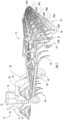
- FIG. 1 illustrates a perspective view of the agricultural machine including a work vehicle 10 and an associated agricultural implement 12.
- FIG. 2 illustrates a perspective view of the agricultural machine, particularly illustrating various components of the implement 12.
- the agricultural machine corresponds to the combination of the work vehicle 10 and the associated agricultural implement 12.
- the vehicle 10 corresponds to an agricultural tractor configured to tow the implement 12, namely a tillage implement (e.g., a cultivator), across a field in a direction of travel (e.g., as indicated by arrow 14 in FIG. 1 ).
- a tillage implement e.g., a cultivator
- the agricultural machine may correspond to any other suitable combination of work vehicle (e.g., an agricultural harvester, a self-propelled sprayer, and/or the like) and agricultural implement (e.g., such as a seeder, fertilizer, sprayer (a towable sprayer or a spray boom of a self-propelled sprayer), mowers, and/or the like).
- work vehicle e.g., an agricultural harvester, a self-propelled sprayer, and/or the like
- agricultural implement e.g., such as a seeder, fertilizer, sprayer (a towable sprayer or a spray boom of a self-propelled sprayer), mowers, and/or the like.
- the term "agricultural machine” may refer not only to combinations of agricultural implements and vehicles, but also to individual agricultural implements and/or vehicles.
- the vehicle 10 may include a frame or chassis 16 configured to support or couple to a plurality of components.
- a pair of front track assemblies 18 (only one of which is shown) and a pair of rear track assemblies 20 may be coupled to the frame 16.
- the track assemblies 18, 20 may, in turn, be configured to support the vehicle 10 relative to the ground and move the vehicle 10 in the direction of travel 14 across the field.
- an operator's cab 22 may be supported by a portion of the frame 16 and may house various input devices (e.g., a user interface 13 shown in FIG. 3 ) for permitting an operator to control the operation of one or more components of the vehicle 10 and/or the implement 12.
- the vehicle 10 may include wheels (not shown) in place of the front and/or rear track assemblies 18, 20.
- the vehicle 10 may include one or more devices for adjusting the speed at which the vehicle 10 and implement 12 move across the field in the direction of travel 14.
- the vehicle 10 may include an engine 24 and a transmission 26 mounted on the frame 16.
- the implement 12 may include an implement frame 28. More specifically, the frame 28 may extend along a longitudinal direction 30 between a forward end 32 and an aft end 34. The frame 28 may also extend along a lateral direction 36 between a first side 38 and a second side 40.
- the frame 28 generally includes a plurality of structural frame members 42, such as beams, bars, and/or the like, configured to support or couple to a plurality of components.
- a hitch assembly 43 may be connected to the frame 28 and configured to couple the implement 12 to the vehicle 10.
- a plurality of wheel assemblies may be coupled to the frame 28, such as a set of centrally located wheels 44 and a set of front pivoting wheels 46, to facilitate towing the implement 12 in the direction of travel 14.
- the frame 28 may support a cultivator 48, which may be configured to till or otherwise break the soil over which the implement 12 travels to create a seedbed.
- the cultivator 48 may include a plurality of ground engaging shanks 50, which are pulled through the soil as the implement 12 moves across the field in the direction of travel 14.
- the ground engaging shanks 50 may be configured to be pivotably mounted to the frame 28 in a manner that permits the penetration depths of the ground engaging shanks 50 to be adjusted.
- each harrow 52 may include a plurality of ground engaging tines 54 configured to engage to the surface of the soil within the field in a manner that levels or otherwise flattens any windrows or ridges in the soil created by the cultivator 48.
- the ground engaging tines 54 may be configured to be pulled through the soil as the implement 12 moves across the field in the direction of travel 14. It should be appreciated that the implement 12 may include any suitable number of harrows 52.
- the implement 12 may include one or more baskets or rotary firming wheels 56.
- the basket(s) 56 may be configured to reduce the number of clods in the soil and/or firm the soil over which the implement 12 travels.
- Each basket 56 may form part of a basket assembly, including one or more basket frame members that rotatably couples the basket 56 to a portion of the implement 12.
- each basket 56 may be configured to be pivotably coupled to one of the harrows 52.
- the basket(s) 56 may be configured to be pivotably coupled to the frame 28 or any other suitable location of the implement 12. It should be appreciated that the implement 12 may include any suitable number of baskets 56.
- the implement 12 may also include any number of suitable actuators (e.g., hydraulic cylinders) for adjusting the relative positioning, penetration depth, and/or down force associated with the various ground engaging tools of the implement 12 (e.g., ground engaging tools 50, 54, 56).
- the implement 12 may include one or more first actuators 60 ( FIG. 2 ) coupled to the frame 28 for raising or lowering the frame 28 relative to the ground, thereby allowing the penetration depth and/or the down pressure of the shanks 50 and ground engaging tines 54 to be adjusted.
- the implement 12 may include one or more second actuators 62 ( FIG. 2 ) coupled to the baskets 56 to allow the baskets 56 to be moved relative to the frame 28 such that the down pressure on the baskets 56 is adjustable.
- one or more sensors such as one or more vision sensor(s) 104
- FIGS. 1 and 2 illustrate examples of various locations for mounting one or more vision sensor(s) 104 for capturing images of the field or other similar image-like data.
- a first vision sensor 104A may be provided at a first location on the implement 12
- a second vision sensor 104B may be provided at a second location on the implement 12
- a third vision sensor 104C may be provided at a third location on the implement 12.
- Each of the first, second, and third vision sensors 104A, 104B, 104C is positioned at the aft end 34 of the implement 12.
- Each vision sensor 104 has a field of view 106 directed at least partially downwardly towards the field surface.
- each of the first, second, and third vision sensors 104A, 104B, 104C has a respective field of view 106A, 106B, 106C generally directed towards the field surface. More particularly, in the illustrated embodiment, the field of view 106A, 106B, 106C of each of the vision sensors 104A, 104B, 104C is directed rearwardly of the implement 12, particularly rearwardly of the baskets 56 along the direction of travel 14.
- the vision sensors 104A, 104B, 104C may be configured to capture data (e.g., vision-based data) indicative of one or more surface conditions of the field surface after the ground working operations of the implement 12. Such data may then be used to determine field surface conditions, such as soil roughness, residue coverage, and/or clod sizes, after such ground working operations.
- data e.g., vision-based data
- Such data may then be used to determine field surface conditions, such as soil roughness, residue coverage, and/or clod sizes, after such ground working operations.
- any suitable number of vision sensors 104 may instead be associated with the implement 12. It should further be appreciated that, while the vision sensors 104 associated with the implement 12 (i.e., the vision sensors 104A, 104B, 104C) are shown as only being positioned at the aft end of the implement 12, the vision sensors 104 may be positioned elsewhere on the implement 12, such as adj acent to any of the other ground engaging tools, such as the shanks 50 or the tines 54, such as vision sensors 104(1), 104(2) shown in FIG. 2 .
- the vision sensors 104 may correspond to any suitable sensing devices configured to detect or capture image or image-like data indicative of the field surface conditions of the field.
- the vision sensors 104 may correspond to any suitable device(s) configured to capture images or other image-like data of the field that allow characteristics of the soil surface such as surface roughness, clod sizes, or other soil features to be detected.
- the vision sensor(s) may correspond to any suitable camera(s), such as single-spectrum camera or a multi-spectrum camera configured to capture images, for example, in the visible light range and/or infrared spectral range.
- the camera(s) may correspond to a single lens camera configured to capture two-dimensional images or a stereo camera(s) having two or more lenses with a separate image sensor for each lens to allow the camera(s) to capture stereographic or three-dimensional images.
- the vision sensor(s) 104 may correspond to any other suitable image capture device(s) and/or other vision sensor(s) capable of capturing "images" or other image-like data of the field.
- the vision sensor(s) 104 may correspond to or include radio detection and ranging (RADAR) sensors and/or light detection and ranging (LIDAR) sensors.
- RADAR radio detection and ranging
- LIDAR light detection and ranging
- one or more secondary sensor(s) 108 may be provided in operative association with the implement 12, particularly the ground engaging tools of the implement 12 that ride along or roll on top of the field surface, in order to calibrate the results of the vision-based data.
- one or more secondary sensors 108A may be mounted or positioned on one or more of the tines 54 and/or one or more secondary sensors 108B may be mounted on or positioned relative to one or more of the baskets 56, such as on a member(s) supporting the basket(s).
- such secondary sensor(s) 108A, 108B may also be configured to detect the movement of the associated ground engaging tool(s) as it rides or rolls along the surface, thereby providing an indication of the surface condition of the field. It should be appreciated that, while only two secondary sensor(s) 108 are illustrated as being associated with the implement 12, any suitable number of secondary sensor(s) 108 may instead be associated with the implement 12.
- the secondary sensor(s) 108 may correspond to any suitable sensing devices configured to detect or capture data indicative of the movement of the associated ground surface engaging tool.
- the secondary sensor(s) 108 may correspond to any suitable device(s) configured to collect tool movement data that allows the surface roughness and/or other soil surface characteristics to be detected.
- the secondary sensor(s) 108 may correspond to or include one or more accelerometers, rotation sensors, load sensor(s), and/or the like.
- the accelerometer(s) may be used to detect the acceleration or movement of the associated ground surface engaging tool (e.g., as the tine(s) 54 deflect and/or as the basket(s) 56 move up and down along the field surface).
- the rotation sensor(s) may be used to detect the angular position of the associated ground surface engaging tool (e.g., as the basket(s) 56 rotate about their attachment point to the frame 28).
- the load sensor(s) may be used to detect load(s) (e.g., stress or strain) on the associated ground surface engaging tool (e.g., as the tine(s) 54 bend or flex).
- such displacement or movement-related parameters associated with the surface engaging tools may be indicative of or otherwise associated with surface conditions of the field, such as surface roughness.
- surface conditions of the field such as surface roughness.
- the tools are displaced by the roughness of or variations in the soil surface within the field.
- the frequency of such displacement may also be used to assess if there are patterns in the surface characteristics, which may indicate that the implement frame 28 is not properly leveled.
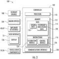
- FIG. 3 a schematic view of one embodiment of a system 100 for determining surface conditions of a field is illustrated in accordance with aspects of the present subject matter.
- the system 100 will be described with reference to the vehicle 10 and the implement 12 described above with reference to FIGS. 1 and 2 .
- the disclosed system 100 may generally be utilized with agricultural machines having any other suitable machine configuration.
- communicative links or electrical couplings of the system 100 shown in FIG. 3 are indicated by dashed lines.
- the system 100 may include a controller 102 and various other components configured to be communicatively coupled to and/or controlled by the controller 102, such as one or more sensors configured to capture data associated with the surface conditions of a field (e.g., vision sensor(s) 104, secondary sensor(s) 108), a user interface (e.g., user interface 13), various components of the implement 12 (e.g., implement actuators 60, 62), and/or various components of the work vehicle 10 (e.g., vehicle drive component(s), such as the engine 24 and/or transmission 26 of the vehicle 10).
- a field e.g., vision sensor(s) 104, secondary sensor(s) 108
- a user interface e.g., user interface 13
- various components of the implement 12 e.g., implement actuators 60, 62
- various components of the work vehicle 10 e.g., vehicle drive component(s), such as the engine 24 and/or transmission 26 of the vehicle 10.
- the user interface 13 described herein may include, without limitation, any combination of input and/or output devices that allow an operator to provide operator inputs to the controller 102 and/or that allow the controller 102 to provide feedback to the operator, such as a keyboard, keypad, pointing device, buttons, knobs, touch sensitive screen, mobile device, audio input device, audio output device, and/or the like.
- the user interface 13 may include an electronic display 13A for displaying information to the operator and/or for receiving inputs from the operator.
- the controller 102 may correspond to any suitable processor-based device(s), such as a computing device or any combination of computing devices.
- the controller 102 may generally include one or more processor(s) 110 and associated memory devices 112 configured to perform a variety of computer-implemented functions (e.g., performing the methods, steps, algorithms, calculations and the like disclosed herein).
- processor refers not only to integrated circuits referred to in the art as being included in a computer, but also refers to a controller, a microcontroller, a microcomputer, a programmable logic controller (PLC), an application specific integrated circuit, and other programmable circuits.
- PLC programmable logic controller
- the memory 112 may generally comprise memory element(s) including, but not limited to, computer readable medium (e.g., random access memory (RAM)), computer readable nonvolatile medium (e.g., a flash memory), a floppy disk, a compact disc-read only memory (CD-ROM), a magneto-optical disk (MOD), a digital versatile disc (DVD) and/or other suitable memory elements.
- RAM random access memory
- RAM computer readable nonvolatile medium
- CD-ROM compact disc-read only memory
- MOD magneto-optical disk
- DVD digital versatile disc
- Such memory 112 may generally be configured to store information accessible to the processor(s) 110, including data 114 that can be retrieved, manipulated, created and/or stored by the processor(s) 110 and instructions 116 that can be executed by the processor(s) 110.
- the controller 102 may correspond to an existing controller for the vehicle 10 or the implement 12 or may correspond to a separate processing device.
- the controller 102 may form all or part of a separate plug-in module that may be installed in operative association with the vehicle 10 or the implement 12 to allow for the disclosed system and method to be implemented without requiring additional software to be uploaded onto existing control devices of the vehicle 10 or the implement 12.
- the data 114 may be stored in one or more databases.
- the memory 112 may include a vision database 118 for storing vision-based data received from the vision sensor(s) 104.
- the vision sensors 104 may be configured to continuously or periodically capture images of the field or other image-like data associated with the surface conditions of the field as an operation is being performed with the field.
- the data transmitted to the controller 102 from the vision sensor(s) 104 may be stored within the vision database 118 for subsequent processing and/or analysis.
- vision-based data or image-like data may include any suitable type of data received from the vision sensor(s) 104 that allows for the field surface conditions of a field to be analyzed by an operator, including photographs or other images, RADAR data, LIDAR data, and/or other image-related data (e.g., scan data and/or the like).
- the memory 112 may include a secondary database 120.
- the secondary database 120 may be configured to store secondary data received from the non-vision-based or secondary sensor(s) 108.
- the secondary sensor(s) 108 may be configured to continuously or periodically monitor movement of the associated surface engaging tool (e.g., tine(s) 54, basket(s) 56, etc.) as an operation is being performed within the field.
- the data transmitted to the controller 102 from the secondary sensor(s) 108 may be stored within the secondary database 120 for subsequent processing and/or analysis.
- secondary data may include any suitable type of non-vision-based data received from the secondary sensor(s) 108 that allows for the determination of surface conditions of a field, including acceleration data, rotational data, load data, and/or the like.
- the instructions 116 stored within the memory 112 of the controller 102 may be executed by the processor(s) 110 to implement a calibration module 124.
- the calibration module 124 may generally be configured to calibrate or correct the initial field surface conditions determined from the vision-based data received from the vision sensor(s) 104 based on the secondary data received from the secondary sensor(s) 108.
- the controller 102 may be configured to analyze the vision-based data to determine a vision-based surface condition corresponding to a characteristic of the field surface, such as surface roughness or clod size.
- the controller 102 may be configured to execute one or more image processing techniques to automatically identify the surface roughness of the field and characterize such surface roughness with a given numerical value, grade, and/or indicator.
- the controller 102 may similarly be configured to analyze the secondary data to determine a secondary surface condition corresponding to the characteristic of the field surface.
- the controller 102 may be configured to correlate the movement of the associated surface engaging tools detected based on the secondary data generated by the secondary sensor(s) to a surface roughness of the field.
- the correlation between the movement of the ground engaging tools and the surface roughness of the field may be pre-determined from experimental data. For instance, in one embodiment, one or more data collection trials may be performed in which the implement 12 is moved across different portions of a field, with each portion representing a set or known surface roughness.
- the movement of the ground engaging tools may be monitored by the controller 102 based on the secondary data detected by the secondary sensor(s) 108 as the implement 12 is moved across the different portions of the field.
- the controller 102 may then be configured to generate a correlation between the movement of the ground engaging tools and the surface roughness across a range of surface roughnesses based on the monitored secondary data.
- the calibration module 124 may be configured to determine a correction value or factor for adjusting or correcting the initial surface condition determined as a function of the vision-based data using the surface condition derived from the secondary data.
- the controller 102 may be configured to determine an error value or differential between the surface conditions determined based on vision-based data and the surface condition determined based on the secondary data.
- the error or differential value may be used directly as the correction factor for subsequently adjusting the initial surface condition, or subsequent surface conditions, deriving from the vision-based data.
- the controller 102 may derive the correction factor at least in part from the error or differential value, e.g., using one or more suitable data-analysis algorithms.
- the controller 102 may then correct or adjust the initial vision-based surface condition by applying the correction factor thereto, thereby allowing the initial vision-derived data to be corrected or calibrated based on the secondary data derived from the secondary sensor(s). For instance, the controller 102 may add or subtract the correction factor from the initial vision-based surface condition to determine a corrected surface condition. Given the established correlation between the secondary data and the monitored surface condition, the corrected surface condition will generally provide a more accurate representation of the surface conditions present within the field.
- the calibration module 124 may perform the correction procedure described above as frequently as necessary to ensure that the field surface condition determined from the vision-based data is more accurate throughout a tillage operation. For instance, the calibration module 124 may perform the disclosed correction procedure continuously, periodically, or only as requested by the operator of the implement 12.
- the controller 102 may also include a communications interface 128 to provide a means for the controller 102 to communicate with any of the various other system components described herein.
- a communications interface 128 may be provided between the communications interface 128 and the vision sensor(s) 104 to allow images or other vision-based data transmitted from the vision sensor(s) 104 to be received by the controller 102.
- one or more communicative links or interfaces may be provided between the communications interface 128 and the secondary sensor(s) 108 to allow data transmitted from the secondary sensor(s) 108 to be received by the controller 102.
- one or more communicative links or interfaces may be provided between the communications interface 128 and the user interface 13 to allow operator inputs to be received by the controller 102 and to allow the controller 102 to control the operation of one or more components of the user interface 13 (e.g., the display 13A when presenting surface condition data to the operator).
- one or more communicative links or interfaces may be provided between the communications interface 128 and the implement actuator(s) 60, 62, the vehicle drive component(s) 24, 26, and/or the like to allow the controller 102 to control the operation of such system components.
- the instructions 116 stored within the memory 112 of the controller 102 may also be executed by the processor(s) 110 to implement a control module 126.
- the control module 126 may be configured to adjust the operation of the implement 12 by controlling one or more components of the implement 12 or the work vehicle 10.
- the controller 102 may be configured to receive an input indicating that the monitored surface condition differs from a target or desired value or range.
- the controller 102 may be configured to automatically adjust the operation of the implement 12 based on the corrected surface condition determined using the vision-based data and as corrected based on the secondary date (e.g., using the correction factor). For example, in one embodiment, the controller 102 may be configured to compare the corrected surface condition to a predetermined threshold established for the monitored surface condition (e.g., a predetermined surface roughness threshold). In such an embodiment, the controller 102 may be configured to adjust the operation of the implement 12 when the corrected surface condition crosses the predetermined threshold, such as when a corrected surface roughness determined for the field exceeds a maximum surface roughness threshold.
- a predetermined threshold established for the monitored surface condition
- the controller 102 may be configured to adjust the operation of the implement 12 when the corrected surface condition crosses the predetermined threshold, such as when a corrected surface roughness determined for the field exceeds a maximum surface roughness threshold.
- the controller 102 may extend or retract the frame actuator 60 in a manner that increases the aggressiveness of the tines 54 and/or extend or retract the basket actuators 62 in a manner that increases the down force applied to the baskets to reduce the surface roughness within the field.
- the operator may determine that the surface condition of the field is too smooth and may request that controller 102 execute appropriate control actions for increasing the roughness of the soil surface, such as by decreasing a down force applied to the tine(s) 54 and/or the basket(s) 56.
- the controller 102 may be configured to automatically adjust the operation of the vehicle 10 based on the corrected field surface condition.
- the controller 102 may be configured to control an operation of one or more vehicle drive components, such as the engine 24 and/or the transmission 26 of the vehicle.
- the controller 102 may be configured to control the operation of the vehicle drive component(s) 24, 26 based on the corrected field surface condition, for example, to slow down the vehicle 10 and implement 12 and/or bring the vehicle 10 and implement 12 to a stop when it is determined that the field surface condition has cross a predetermined threshold and/or has fallen outside a target range.
- the controller 102 may be configured to receive a control action input from the operator associated with the selection of a specific control action for adjusting the operation of one or more of the components of the implement 12 or the vehicle 10 to improve the field surface conditions.
- a control action input from the operator associated with the selection of a specific control action for adjusting the operation of one or more of the components of the implement 12 or the vehicle 10 to improve the field surface conditions For example, in one embodiment, an operator may determine that the corrected field surface condition is outside of desired tolerances and may instruct the controller 102 to execute a specific control action, such as the ones described above, to adjust the field surface conditions.
- control actions may be executed directly by the controller 102 or indirectly via communications with a separate controller.
- the controller 102 may be configured to execute the implement-related control actions directly while being configured to execute the vehicle-related control actions by transmitting suitable instructions or requests to a vehicle-based controller of the vehicle 10 towing the implement 12 (e.g., using an ISObus communications protocol).
- the controller 102 when the controller 102 corresponds to a vehicle controller of the vehicle towing the implement 12, the controller 102 may be configured to execute the vehicle-related control actions directly while being configured to execute the implement-related control actions by transmitting suitable instructions or requests to an implement-based controller of the implement 12 (e.g., using an ISObus communications protocol). In other embodiments, the controller 102 may be configured to execute both the implement-based control actions and the vehicle-based control actions directly or the controller 102 may be configured to execute both of such control action types indirectly via communications with a separate controller.
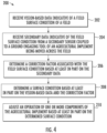
- FIG. 4 a flow diagram of one embodiment of a method 200 for determining field surface conditions is illustrated in accordance with aspects of the present subject matter.
- the method 200 will be described herein with reference to the work vehicle 10 and the implement 12 shown in FIGS. 1 and 2 , as well as the various system components shown in FIG. 3 .
- the disclosed method 200 may be implemented with work vehicles and/or implements having any other suitable configurations and/or within systems having any other suitable system configuration.
- FIG. 4 depicts steps performed in a particular order for purposes of illustration and discussion, the methods discussed herein are not limited to any particular order or arrangement.
- steps of the method disclosed herein can be omitted, rearranged, combined, and/or adapted in various ways without deviating from the scope of the present disclosure.
- the method 200 may include receiving vision-based data indicative of a field surface condition of a field.
- the controller 102 may be configured to receive an input(s) from one or more sensors configured to provide an indication of the surface condition of the field, such as by receiving vision-based data from one or more vision sensors 104 provided in operative association with the implement 12 that is indicative of the surface roughness within the field.
- the method 200 may further include receiving secondary data indicative of the field surface condition from a secondary sensor coupled to a ground engaging tool of an agricultural implement being moved across the field.
- the controller 102 may be configured to receive an input(s) from one or more non-vision-based sensors configured to provide an indication of displacement or movement of an associated surface engaging tool, such as by receiving secondary data from one or more secondary sensors 108 provided in operative association with the tines 54 and/or baskets 56.
- the method 200 may include determining a correction factor associated with the field surface condition based at least in part on the secondary data.
- the controller 102 may be configured to analyze the vision-based data to determine a vision-based surface condition and the secondary data to determine a secondary surface condition. The controller 102 may then compare the vision-based surface condition to the secondary surface condition to determine a correction factor, which may, for example, be equal to the error or differential between the surface condition derived from the vision-based and non-vision-based sensor data.
- the method 200 may include determining a surface condition based at least in part on the vision-based data and the correction factor.
- the initial vision-based surface condition generated from the vision-based data may be corrected based on the correction factor.
- the correction factor may be added to or subtracted from each initial vision-based surface condition to determine an actual or corrected surface condition for the field.
- the method 200 may include adjusting an operation of one or more components of the agricultural implement based at least in part on the determined surface condition.
- the controller 102 may be configured to adjust the operation of the implement 12 and/or the work vehicle 10 in response to an input indicating that the corrected surface condition is not within tolerances.
- the input may be received from an operator of the implement 12 or may be automatically generated by the controller 102 based on the comparison of the corrected surface condition to one or more predetermined thresholds and/or target ranges.
- the steps of the method 200 are performed by the controller 102 upon loading and executing software code or instructions which are tangibly stored on a tangible computer readable medium, such as on a magnetic medium, e.g., a computer hard drive, an optical medium, e.g., an optical disc, solid-state memory, e.g., flash memory, or other storage media known in the art.
- a tangible computer readable medium such as on a magnetic medium, e.g., a computer hard drive, an optical medium, e.g., an optical disc, solid-state memory, e.g., flash memory, or other storage media known in the art.
- any of the functionality performed by the controller 102 described herein, such as the method 200 are implemented in software code or instructions which are tangibly stored on a tangible computer readable medium.
- the controller 102 loads the software code or instructions via a direct interface with the computer readable medium or via a wired and/or wireless network. Upon loading and executing such software code or instructions by the controller 102
- software code or “code” used herein refers to any instructions or set of instructions that influence the operation of a computer or controller. They may exist in a computer-executable form, such as machine code, which is the set of instructions and data directly executed by a computer's central processing unit or by a controller, a human-understandable form, such as source code, which may be compiled in order to be executed by a computer's central processing unit or by a controller, or an intermediate form, such as object code, which is produced by a compiler.
- the term "software code” or “code” also includes any human-understandable computer instructions or set of instructions, e.g., a script, that may be executed on the fly with the aid of an interpreter executed by a computer's central processing unit or by a controller.
Landscapes
- Life Sciences & Earth Sciences (AREA)
- Engineering & Computer Science (AREA)
- Environmental Sciences (AREA)
- Soil Sciences (AREA)
- Mechanical Engineering (AREA)
- Physics & Mathematics (AREA)
- General Physics & Mathematics (AREA)
- Electromagnetism (AREA)
- Computer Vision & Pattern Recognition (AREA)
- Theoretical Computer Science (AREA)
- Quality & Reliability (AREA)
- Remote Sensing (AREA)
- Radar, Positioning & Navigation (AREA)
- Computer Networks & Wireless Communication (AREA)
- Soil Working Implements (AREA)
- Length Measuring Devices By Optical Means (AREA)
Claims (13)
- System (100) zum Bestimmen von Feldoberflächeneigenschaften, wobei das System (100) ein Rahmenelement (28), ein mit dem Boden eingreifendes Werkzeug (56), das mit dem Rahmenelement (28) gekoppelt ist, wobei das mit dem Boden eingreifende Werkzeug (56) dazu eingerichtet ist, mit dem Boden innerhalb eines Felds einzugreifen, wenn ein landwirtschaftliches Arbeitsgerät (12) über das Feld bewegt wird, und einen Bildsensor (104) mit einem Sichtfeld (106), das in Richtung eines Abschnitts einer Oberfläche des Felds gerichtet ist, aufweist, wobei der Bildsensor (104) dazu eingerichtet ist, bildbasierte Daten zu erfassen, die kennzeichnend für eine Feldoberflächeneigenschaft des Felds sind, wobei das System (100) gekennzeichnet ist durch:einen sekundären Sensor (108), der mit dem mit dem Boden eingreifenden Werkzeug (56) gekoppelt ist, wobei der sekundäre Sensor (108) dazu eingerichtet ist, sekundäre Daten zu erfassen, die kennzeichnend für die Feldoberflächeneigenschaft sind; undein Steuergerät (102), das kommunikativ mit dem Bildsensor (104) und dem sekundären Sensor (108) gekoppelt ist, wobei das Steuergerät (102) dazu eingerichtet ist, eine initiale Oberflächeneigenschaft, die zugehörig zu der Feldoberflächeneigenschaft ist, in Abhängigkeit von den bildbasierten Daten zu bestimmen und die initiale Oberflächeneigenschaft basierend auf zumindest teilweise den sekundären Daten, die von dem sekundären Sensor (108) empfangen wurden, anzupassen;wobei:- das Steuergerät (102) dazu eingerichtet ist, die initiale Oberflächeneigenschaft durch Bestimmen eines Korrekturfaktors, der auf den sekundären Daten basiert, die von dem sekundären Sensor (108) empfangen wurden, und durch Anwenden des Korrekturfaktors auf die initiale Oberflächeneigenschaft anzupassen, um eine korrigierte Oberflächeneigenschaft zu bestimmen,- der sekundäre Sensor (108) in Zusammenwirkung mit dem mit dem Boden eingreifenden Werkzeug (56) vorgesehen ist, so dass der sekundäre Sensor (108) einen Parameter erfasst, der kennzeichnend für eine Bewegung des mit dem Boden eingreifenden Werkzeugs (56) ist, wenn das mit dem Boden eingreifende Werkzeug (56) entlang einer Oberfläche des Felds bewegt wird.
- System (100) nach Anspruch 1, wobei der Korrekturfaktor basierend auf zumindest teilweise einer Differenz aus der initialen Oberflächeneigenschaft, die in Abhängigkeit von den bildbasierten Daten bestimmt wurde, und einer zweiten Oberflächeneigenschaft, die zugehörig zu der Feldoberflächeneigenschaft ist, die in Abhängigkeit von den sekundären Daten bestimmt wurde, die von dem sekundären Sensor (108) empfangen wurden, bestimmt wird.
- System (100) nach Anspruch 1, wobei das Steuergerät (102) des Weiteren dazu eingerichtet ist, einen Betrieb von einer oder mehreren Komponenten des landwirtschaftlichen Arbeitsgeräts (12) basierend auf zumindest teilweise der korrigierten Oberflächeneigenschaft anzupassen.
- System (100) nach Anspruch 1, wobei die Feldoberflächeneigenschaft eine Bodenoberflächenrauheit des Felds ist.
- System (100) nach Anspruch 4, wobei das mit dem Boden eingreifende Werkzeug (56) zumindest einen aus einem Zinken (54) oder einer Korbanordnung (56) des landwirtschaftlichen Arbeitsgeräts (12) aufweist.
- System (100) nach Anspruch 4, wobei das Steuergerät (102) dazu eingerichtet ist, eine erste Bodenrauheit des Felds in Abhängigkeit von den bildbasierten Daten, die von dem Bildsensor (104) empfangen wurden, und eine zweite Bodenrauheit des Felds in Abhängigkeit von den sekundären Daten, die von dem sekundären Sensor (108) empfangen wurden, zu bestimmen, wobei das Steuergerät (102) des Weiteren dazu eingerichtet ist, einen Korrekturfaktor basierend auf der ersten und der zweiten Bodenrauheit zu bestimmen und den Korrekturfaktor anzuwenden, um nachfolgende Bodenoberflächenrauheiten, die basierend auf den bildbasierten Daten bestimmt wurden, die von dem Bildsensor (104) empfangen wurden, anzupassen.
- System (100) nach Anspruch 1, wobei der sekundäre Sensor (108) zumindest einen aus einem Beschleunigungssensor, einem Lastsensor oder einem Rotationssensor aufweist.
- System (100) nach Anspruch 1, wobei der Bildsensor (104) zumindest einen aus einer Kamera oder einem LIDAR-Gerät (Light Detection and Ranging) aufweist.
- System (100) nach Anspruch 1, wobei das Sichtfeld (106) des Bildsensors (104) in Richtung eines in Bewegungsrichtung (14) des landwirtschaftlichen Arbeitsgeräts (12) rückwärtigen Abschnitts des Felds relativ zu dem landwirtschaftlichen Arbeitsgerät (12) gerichtet ist.
- Verfahren (200) zum Bestimmen von Feldoberflächeneigenschaften, wobei das Verfahren (200) aufweist:Empfangen, mittels einer oder mehrerer Verarbeitungseinrichtungen, von bildbasierten Daten, die kennzeichnend für eine Feldoberflächeneigenschaft eines Felds sind;Empfangen, mittels der einen oder den mehreren Verarbeitungseinrichtungen, von sekundären Daten, die kennzeichnend für die Feldoberflächeneigenschaft sind, von einem sekundären Sensor (108), der mit einem mit dem Boden eingreifenden Werkzeug (56) eines landwirtschaftlichen Arbeitsgeräts (12) gekoppelt ist, das über das Feld bewegt wird;Bestimmen, mittels der einen oder den mehreren Verarbeitungseinrichtungen, eines Korrekturfaktors, der zugehörig zu der Feldoberflächeneigenschaft ist, basierend auf zumindest teilweise den sekundären Daten;Bestimmen, mittels der einen oder den mehreren Verarbeitungseinrichtungen, einer Oberflächeneigenschaft basierend auf zumindest teilweise den bildbasierten Daten und dem Korrekturfaktor; undAnpassen, mittels der einen oder den mehreren Verarbeitungseinrichtungen, eines Betriebs einer oder mehrerer Komponenten des landwirtschaftlichen Arbeitsgeräts (12) basierend auf zumindest teilweise der bestimmten Oberflächeneigenschaft,wobei die bildbasierten Daten von einem Bildsensor (104) empfangen werden, wobei der Bildsensor (104) in Zusammenwirkung mit dem landwirtschaftlichen Arbeitsgerät (12) vorgesehen ist und ein Sichtfeld (106) aufweist, das in Richtung eines Abschnitts einer Oberfläche des Felds gerichtet ist.
- Verfahren (200) nach Anspruch 10, wobei der Korrekturfaktor basierend auf zumindest teilweise einer Differenz aus einer ersten Oberflächeneigenschaft, die in Abhängigkeit von den bildbasierten Daten bestimmt wurde, und einer zweiten Oberflächeneigenschaft, die in Abhängigkeit von den sekundären Daten bestimmt wurde, bestimmt wird.
- Verfahren (200) nach Anspruch 11, wobei das Bestimmen der Oberflächeneigenschaft ein Anpassen der ersten Oberflächeneigenschaft unter Anwendung des Korrekturfaktors aufweist.
- Verfahren (200) nach Anspruch 10, wobei die Feldoberflächeneigenschaft eine Bodenoberflächenrauheit des Felds ist, wobei der sekundäre Sensor (108) in Zusammenwirkung mit dem mit dem Boden eingreifenden Werkzeug (56) derart vorgesehen ist, dass der sekundäre Sensor (108) einen Parameter erfasst, der kennzeichnend für eine Bewegung des mit dem Boden eingreifenden Werkzeugs (56) ist, wenn das mit dem Boden eingreifende Werkzeug (56) entlang einer Oberfläche des Felds bewegt wird.
Applications Claiming Priority (2)
| Application Number | Priority Date | Filing Date | Title |
|---|---|---|---|
| US16/538,996 US12007222B2 (en) | 2019-08-13 | 2019-08-13 | System and method for determining field surface conditions using vision-based data and data from a secondary source |
| PCT/IB2020/057589 WO2021028847A1 (en) | 2019-08-13 | 2020-08-12 | System and method for determining field surface conditions using vision-based data and data from a secondary source |
Publications (3)
| Publication Number | Publication Date |
|---|---|
| EP4014075A1 EP4014075A1 (de) | 2022-06-22 |
| EP4014075A4 EP4014075A4 (de) | 2023-10-18 |
| EP4014075B1 true EP4014075B1 (de) | 2024-10-30 |
Family
ID=74567206
Family Applications (1)
| Application Number | Title | Priority Date | Filing Date |
|---|---|---|---|
| EP20851804.3A Active EP4014075B1 (de) | 2019-08-13 | 2020-08-12 | System und verfahren zur bestimmung von feldflächenverhältnissen unter verwendung von sichtbasierten daten und daten aus einer sekundären quelle |
Country Status (4)
| Country | Link |
|---|---|
| US (1) | US12007222B2 (de) |
| EP (1) | EP4014075B1 (de) |
| CA (1) | CA3146250A1 (de) |
| WO (1) | WO2021028847A1 (de) |
Families Citing this family (14)
| Publication number | Priority date | Publication date | Assignee | Title |
|---|---|---|---|---|
| DK3476188T3 (da) * | 2017-10-30 | 2022-08-08 | Kverneland Group Les Landes Genusson | Fremgangsmåde og system til bestemmelse og lagring af overfladeforhold for en mark |
| US11191204B2 (en) * | 2019-02-18 | 2021-12-07 | Cnh Industrial Canada, Ltd. | System and method for monitoring soil conditions within a field |
| US11610295B2 (en) * | 2019-12-09 | 2023-03-21 | Cnh Industrial America Llc | System and method for detecting the operating condition of components of an implement |
| US11718304B2 (en) * | 2020-03-06 | 2023-08-08 | Deere & Comoanv | Method and system for estimating surface roughness of ground for an off-road vehicle to control an implement |
| US11684005B2 (en) | 2020-03-06 | 2023-06-27 | Deere & Company | Method and system for estimating surface roughness of ground for an off-road vehicle to control an implement |
| US11667171B2 (en) | 2020-03-12 | 2023-06-06 | Deere & Company | Method and system for estimating surface roughness of ground for an off-road vehicle to control steering |
| US11753016B2 (en) | 2020-03-13 | 2023-09-12 | Deere & Company | Method and system for estimating surface roughness of ground for an off-road vehicle to control ground speed |
| US11685381B2 (en) | 2020-03-13 | 2023-06-27 | Deere & Company | Method and system for estimating surface roughness of ground for an off-road vehicle to control ground speed |
| US11576297B2 (en) * | 2020-05-28 | 2023-02-14 | Deere & Company | Automatic selective control valve (SVC) configuration detection, and operation assignment, directionality confirmation, and calibration for towable implements towable by work vehicles |
| NL2026042B1 (en) * | 2020-07-10 | 2022-03-15 | Ploeger Oxbo Europe B V | A method for performing an agricultural operation on a predefined working area which is processed by means of an agriculture machine |
| US12207578B2 (en) | 2022-08-17 | 2025-01-28 | Cnh Industrial America Llc | Finishing tool assembly position control system for an agricultural tillage implement |
| US20240090361A1 (en) * | 2022-09-16 | 2024-03-21 | Cnh Industrial America Llc | System and method for determining soil compaction layer location during agricultural implement operation |
| US20240172580A1 (en) * | 2022-11-30 | 2024-05-30 | Cnh Industrial America Llc | System and method for automatically leveling an agricultural implement using forward-looking sensor data |
| JP2026007236A (ja) * | 2024-07-02 | 2026-01-16 | 株式会社クボタ | 判定システムおよび判定方法 |
Family Cites Families (22)
| Publication number | Priority date | Publication date | Assignee | Title |
|---|---|---|---|---|
| US6041582A (en) | 1998-02-20 | 2000-03-28 | Case Corporation | System for recording soil conditions |
| BRPI0806559B1 (pt) | 2007-01-08 | 2018-04-10 | Precision Planting, Inc. | Sistema de monitor para semeadeira de sementes agrícolas |
| US9585307B2 (en) | 2007-07-03 | 2017-03-07 | Kyle H. Holland | Optical real-time soil sensor and auto-calibration methods |
| US8204689B2 (en) | 2007-10-24 | 2012-06-19 | Veris Technologies, Inc. | Mobile soil mapping system for collecting soil reflectance measurements |
| US8448587B2 (en) | 2010-01-26 | 2013-05-28 | Cnh Canada, Ltd. | Row unit bounce monitoring system |
| SE535699C2 (sv) | 2011-01-26 | 2012-11-13 | Vaederstad Verken Ab | Lantbruksredskap samt metod för bearbetning av jord |
| US8862339B2 (en) | 2012-08-09 | 2014-10-14 | Cnh Industrial Canada, Ltd. | System and method for controlling soil finish from an agricultural implement |
| US20140277959A1 (en) | 2013-03-15 | 2014-09-18 | Jesse L. Wagers | Multi-seed planter control system and method for the same |
| US9945832B2 (en) | 2014-03-03 | 2018-04-17 | Damian Bover Trobat | Apparatus and method to determine ground properties by traction anchors and sensors |
| US9554098B2 (en) | 2014-04-25 | 2017-01-24 | Deere & Company | Residue monitoring and residue-based control |
| EP3133910B1 (de) | 2014-04-25 | 2018-07-11 | CNH Industrial Belgium N.V. | System zur montage eines landwirtschaftlichen bodenanalysators an ein landwirtschaftlichen anbaugerät |
| US20160029547A1 (en) | 2014-07-30 | 2016-02-04 | Deere & Company | Sensing the soil profile behind a soil-engaging implement |
| EP3157322A4 (de) | 2015-07-13 | 2017-11-15 | Agerpoint, Inc. | Modulare systeme und verfahren zur bestimmung der ernteleistung mit hoher auflösenden georeferenzierten sensoren |
| BR112018005312B1 (pt) | 2015-09-18 | 2022-02-15 | Precision Planting Llc | Equipamento agrícola, e método de controle de uma plantadeira |
| US11266056B2 (en) | 2015-10-23 | 2022-03-08 | Deere & Company | System and method for residue detection and implement control |
| US10408645B2 (en) | 2016-11-01 | 2019-09-10 | Deere & Company | Correcting bias in parameter monitoring |
| US10194574B2 (en) | 2016-11-18 | 2019-02-05 | Cnh Industrial America Llc | System for adjusting smoothing tools of a harrow according to location |
| US10123475B2 (en) | 2017-02-03 | 2018-11-13 | Cnh Industrial America Llc | System and method for automatically monitoring soil surface roughness |
| US10262206B2 (en) | 2017-05-16 | 2019-04-16 | Cnh Industrial America Llc | Vision-based system for acquiring crop residue data and related calibration methods |
| US10757859B2 (en) | 2017-07-20 | 2020-09-01 | Deere & Company | System for optimizing platform settings based on crop state classification |
| WO2019040552A1 (en) | 2017-08-23 | 2019-02-28 | Topcon Positioning Systems, Inc. | SYSTEM AND METHOD FOR QUANTIFICATION OF SOIL ROUGHNESS |
| US11718304B2 (en) | 2020-03-06 | 2023-08-08 | Deere & Comoanv | Method and system for estimating surface roughness of ground for an off-road vehicle to control an implement |
-
2019
- 2019-08-13 US US16/538,996 patent/US12007222B2/en active Active
-
2020
- 2020-08-12 EP EP20851804.3A patent/EP4014075B1/de active Active
- 2020-08-12 CA CA3146250A patent/CA3146250A1/en active Pending
- 2020-08-12 WO PCT/IB2020/057589 patent/WO2021028847A1/en not_active Ceased
Also Published As
| Publication number | Publication date |
|---|---|
| US20210048290A1 (en) | 2021-02-18 |
| US12007222B2 (en) | 2024-06-11 |
| CA3146250A1 (en) | 2021-02-18 |
| EP4014075A4 (de) | 2023-10-18 |
| WO2021028847A1 (en) | 2021-02-18 |
| EP4014075A1 (de) | 2022-06-22 |
Similar Documents
| Publication | Publication Date | Title |
|---|---|---|
| EP4014075B1 (de) | System und verfahren zur bestimmung von feldflächenverhältnissen unter verwendung von sichtbasierten daten und daten aus einer sekundären quelle | |
| US10820478B1 (en) | System and method for providing a visual indication of field surface conditions | |
| US11197408B2 (en) | Ultrasonic sensors for field roughness measurement | |
| EP3357316B1 (de) | System und verfahren zur automatischen überwachung der bodenoberflächenrauhigkeit | |
| EP3815480B1 (de) | System und verfahren zur detektion von werkzeugverstopfung eines landwirtschaftlichen anbaugeräts auf basis von rückstandsunterschieden | |
| US11343956B2 (en) | System and method for monitoring soil conditions within a field | |
| EP3815482B1 (de) | Vorrichtung und verfahren zur detektion der ebenheit von werkzeugen eines bodenbearbeitungsgeräts auf basis der werkzeugbelastung | |
| US10916028B1 (en) | Sensor assembly for an agricultural implement and related systems and methods for monitoring field surface conditions | |
| EP4033875B1 (de) | System und verfahren zur bereitstellung eines visuellen indikators für das feldoberflächenprofil | |
| US20230345852A1 (en) | System and method for detecting levelness of tools of a tillage implement based on material flow | |
| US11470763B2 (en) | System and method for determining subsurface soil layer characteristics based on RADAR and load data | |
| US11665991B2 (en) | System and method for monitoring the levelness of a multi-wing agricultural implement | |
| US20210132028A1 (en) | Systems and methods for monitoring field conditions | |
| US20180279541A1 (en) | Seedbed condition monitoring system when performing field operations | |
| US11711994B2 (en) | System and method for monitoring the condition of a lateral swath of a seedbed with a seedbed floor detection assembly | |
| US20230196851A1 (en) | Agricultural system and method for monitoring wear rates of agricultural implements | |
| US12514141B2 (en) | System and method for determining frame position of an agricultural implement | |
| US20250216554A1 (en) | System and Method for Automatically Monitoring Surface Roughness of a Field During an Agricultural Operation | |
| CA3017315C (en) | Ultrasonic sensors for field roughness measurement |
Legal Events
| Date | Code | Title | Description |
|---|---|---|---|
| STAA | Information on the status of an ep patent application or granted ep patent |
Free format text: STATUS: THE INTERNATIONAL PUBLICATION HAS BEEN MADE |
|
| PUAI | Public reference made under article 153(3) epc to a published international application that has entered the european phase |
Free format text: ORIGINAL CODE: 0009012 |
|
| STAA | Information on the status of an ep patent application or granted ep patent |
Free format text: STATUS: REQUEST FOR EXAMINATION WAS MADE |
|
| 17P | Request for examination filed |
Effective date: 20220314 |
|
| AK | Designated contracting states |
Kind code of ref document: A1 Designated state(s): AL AT BE BG CH CY CZ DE DK EE ES FI FR GB GR HR HU IE IS IT LI LT LU LV MC MK MT NL NO PL PT RO RS SE SI SK SM TR |
|
| DAV | Request for validation of the european patent (deleted) | ||
| DAX | Request for extension of the european patent (deleted) | ||
| A4 | Supplementary search report drawn up and despatched |
Effective date: 20230919 |
|
| RIC1 | Information provided on ipc code assigned before grant |
Ipc: G01V 8/00 20060101ALI20230913BHEP Ipc: G01B 21/30 20060101ALI20230913BHEP Ipc: A01B 76/00 20060101ALI20230913BHEP Ipc: A01B 35/32 20060101ALI20230913BHEP Ipc: G01V 9/00 20060101AFI20230913BHEP |
|
| GRAP | Despatch of communication of intention to grant a patent |
Free format text: ORIGINAL CODE: EPIDOSNIGR1 |
|
| STAA | Information on the status of an ep patent application or granted ep patent |
Free format text: STATUS: GRANT OF PATENT IS INTENDED |
|
| INTG | Intention to grant announced |
Effective date: 20240521 |
|
| GRAS | Grant fee paid |
Free format text: ORIGINAL CODE: EPIDOSNIGR3 |
|
| GRAA | (expected) grant |
Free format text: ORIGINAL CODE: 0009210 |
|
| STAA | Information on the status of an ep patent application or granted ep patent |
Free format text: STATUS: THE PATENT HAS BEEN GRANTED |
|
| AK | Designated contracting states |
Kind code of ref document: B1 Designated state(s): AL AT BE BG CH CY CZ DE DK EE ES FI FR GB GR HR HU IE IS IT LI LT LU LV MC MK MT NL NO PL PT RO RS SE SI SK SM TR |
|
| REG | Reference to a national code |
Ref country code: GB Ref legal event code: FG4D |
|
| REG | Reference to a national code |
Ref country code: CH Ref legal event code: EP |
|
| REG | Reference to a national code |
Ref country code: IE Ref legal event code: FG4D |
|
| REG | Reference to a national code |
Ref country code: DE Ref legal event code: R096 Ref document number: 602020040495 Country of ref document: DE |
|
| REG | Reference to a national code |
Ref country code: LT Ref legal event code: MG9D |
|
| REG | Reference to a national code |
Ref country code: NL Ref legal event code: MP Effective date: 20241030 |
|
| PG25 | Lapsed in a contracting state [announced via postgrant information from national office to epo] |
Ref country code: IS Free format text: LAPSE BECAUSE OF FAILURE TO SUBMIT A TRANSLATION OF THE DESCRIPTION OR TO PAY THE FEE WITHIN THE PRESCRIBED TIME-LIMIT Effective date: 20250228 Ref country code: HR Free format text: LAPSE BECAUSE OF FAILURE TO SUBMIT A TRANSLATION OF THE DESCRIPTION OR TO PAY THE FEE WITHIN THE PRESCRIBED TIME-LIMIT Effective date: 20241030 Ref country code: PT Free format text: LAPSE BECAUSE OF FAILURE TO SUBMIT A TRANSLATION OF THE DESCRIPTION OR TO PAY THE FEE WITHIN THE PRESCRIBED TIME-LIMIT Effective date: 20250228 |
|
| PG25 | Lapsed in a contracting state [announced via postgrant information from national office to epo] |
Ref country code: FI Free format text: LAPSE BECAUSE OF FAILURE TO SUBMIT A TRANSLATION OF THE DESCRIPTION OR TO PAY THE FEE WITHIN THE PRESCRIBED TIME-LIMIT Effective date: 20241030 Ref country code: NL Free format text: LAPSE BECAUSE OF FAILURE TO SUBMIT A TRANSLATION OF THE DESCRIPTION OR TO PAY THE FEE WITHIN THE PRESCRIBED TIME-LIMIT Effective date: 20241030 |
|
| REG | Reference to a national code |
Ref country code: AT Ref legal event code: MK05 Ref document number: 1737417 Country of ref document: AT Kind code of ref document: T Effective date: 20241030 |
|
| PG25 | Lapsed in a contracting state [announced via postgrant information from national office to epo] |
Ref country code: BG Free format text: LAPSE BECAUSE OF FAILURE TO SUBMIT A TRANSLATION OF THE DESCRIPTION OR TO PAY THE FEE WITHIN THE PRESCRIBED TIME-LIMIT Effective date: 20241030 |
|
| PG25 | Lapsed in a contracting state [announced via postgrant information from national office to epo] |
Ref country code: ES Free format text: LAPSE BECAUSE OF FAILURE TO SUBMIT A TRANSLATION OF THE DESCRIPTION OR TO PAY THE FEE WITHIN THE PRESCRIBED TIME-LIMIT Effective date: 20241030 |
|
| PG25 | Lapsed in a contracting state [announced via postgrant information from national office to epo] |
Ref country code: NO Free format text: LAPSE BECAUSE OF FAILURE TO SUBMIT A TRANSLATION OF THE DESCRIPTION OR TO PAY THE FEE WITHIN THE PRESCRIBED TIME-LIMIT Effective date: 20250130 |
|
| PG25 | Lapsed in a contracting state [announced via postgrant information from national office to epo] |
Ref country code: LV Free format text: LAPSE BECAUSE OF FAILURE TO SUBMIT A TRANSLATION OF THE DESCRIPTION OR TO PAY THE FEE WITHIN THE PRESCRIBED TIME-LIMIT Effective date: 20241030 Ref country code: AT Free format text: LAPSE BECAUSE OF FAILURE TO SUBMIT A TRANSLATION OF THE DESCRIPTION OR TO PAY THE FEE WITHIN THE PRESCRIBED TIME-LIMIT Effective date: 20241030 Ref country code: GR Free format text: LAPSE BECAUSE OF FAILURE TO SUBMIT A TRANSLATION OF THE DESCRIPTION OR TO PAY THE FEE WITHIN THE PRESCRIBED TIME-LIMIT Effective date: 20250131 |
|
| PG25 | Lapsed in a contracting state [announced via postgrant information from national office to epo] |
Ref country code: PL Free format text: LAPSE BECAUSE OF FAILURE TO SUBMIT A TRANSLATION OF THE DESCRIPTION OR TO PAY THE FEE WITHIN THE PRESCRIBED TIME-LIMIT Effective date: 20241030 |
|
| PG25 | Lapsed in a contracting state [announced via postgrant information from national office to epo] |
Ref country code: RS Free format text: LAPSE BECAUSE OF FAILURE TO SUBMIT A TRANSLATION OF THE DESCRIPTION OR TO PAY THE FEE WITHIN THE PRESCRIBED TIME-LIMIT Effective date: 20250130 |
|
| PG25 | Lapsed in a contracting state [announced via postgrant information from national office to epo] |
Ref country code: SM Free format text: LAPSE BECAUSE OF FAILURE TO SUBMIT A TRANSLATION OF THE DESCRIPTION OR TO PAY THE FEE WITHIN THE PRESCRIBED TIME-LIMIT Effective date: 20241030 |
|
| PG25 | Lapsed in a contracting state [announced via postgrant information from national office to epo] |
Ref country code: DK Free format text: LAPSE BECAUSE OF FAILURE TO SUBMIT A TRANSLATION OF THE DESCRIPTION OR TO PAY THE FEE WITHIN THE PRESCRIBED TIME-LIMIT Effective date: 20241030 |
|
| PG25 | Lapsed in a contracting state [announced via postgrant information from national office to epo] |
Ref country code: EE Free format text: LAPSE BECAUSE OF FAILURE TO SUBMIT A TRANSLATION OF THE DESCRIPTION OR TO PAY THE FEE WITHIN THE PRESCRIBED TIME-LIMIT Effective date: 20241030 |
|
| PG25 | Lapsed in a contracting state [announced via postgrant information from national office to epo] |
Ref country code: RO Free format text: LAPSE BECAUSE OF FAILURE TO SUBMIT A TRANSLATION OF THE DESCRIPTION OR TO PAY THE FEE WITHIN THE PRESCRIBED TIME-LIMIT Effective date: 20241030 |
|
| PG25 | Lapsed in a contracting state [announced via postgrant information from national office to epo] |
Ref country code: SK Free format text: LAPSE BECAUSE OF FAILURE TO SUBMIT A TRANSLATION OF THE DESCRIPTION OR TO PAY THE FEE WITHIN THE PRESCRIBED TIME-LIMIT Effective date: 20241030 |
|
| PG25 | Lapsed in a contracting state [announced via postgrant information from national office to epo] |
Ref country code: CZ Free format text: LAPSE BECAUSE OF FAILURE TO SUBMIT A TRANSLATION OF THE DESCRIPTION OR TO PAY THE FEE WITHIN THE PRESCRIBED TIME-LIMIT Effective date: 20241030 |
|
| REG | Reference to a national code |
Ref country code: DE Ref legal event code: R097 Ref document number: 602020040495 Country of ref document: DE |
|
| PLBE | No opposition filed within time limit |
Free format text: ORIGINAL CODE: 0009261 |
|
| STAA | Information on the status of an ep patent application or granted ep patent |
Free format text: STATUS: NO OPPOSITION FILED WITHIN TIME LIMIT |
|
| PG25 | Lapsed in a contracting state [announced via postgrant information from national office to epo] |
Ref country code: SE Free format text: LAPSE BECAUSE OF FAILURE TO SUBMIT A TRANSLATION OF THE DESCRIPTION OR TO PAY THE FEE WITHIN THE PRESCRIBED TIME-LIMIT Effective date: 20241030 |
|
| 26N | No opposition filed |
Effective date: 20250731 |
|
| PGFP | Annual fee paid to national office [announced via postgrant information from national office to epo] |
Ref country code: DE Payment date: 20250827 Year of fee payment: 6 |
|
| PGFP | Annual fee paid to national office [announced via postgrant information from national office to epo] |
Ref country code: IT Payment date: 20250825 Year of fee payment: 6 |
|
| PGFP | Annual fee paid to national office [announced via postgrant information from national office to epo] |
Ref country code: GB Payment date: 20250826 Year of fee payment: 6 |
|
| PGFP | Annual fee paid to national office [announced via postgrant information from national office to epo] |
Ref country code: FR Payment date: 20250825 Year of fee payment: 6 |
|
| REG | Reference to a national code |
Ref country code: CH Ref legal event code: H13 Free format text: ST27 STATUS EVENT CODE: U-0-0-H10-H13 (AS PROVIDED BY THE NATIONAL OFFICE) Effective date: 20260324 |
|
| PG25 | Lapsed in a contracting state [announced via postgrant information from national office to epo] |
Ref country code: MC Free format text: LAPSE BECAUSE OF FAILURE TO SUBMIT A TRANSLATION OF THE DESCRIPTION OR TO PAY THE FEE WITHIN THE PRESCRIBED TIME-LIMIT Effective date: 20241030 |
|
| PG25 | Lapsed in a contracting state [announced via postgrant information from national office to epo] |
Ref country code: LU Free format text: LAPSE BECAUSE OF NON-PAYMENT OF DUE FEES Effective date: 20250812 |