EP4013722B1 - Vorrichtung zur steuerung der thermischen hydrolysedekompression und prozessanlage mit solch einer vorrichtung - Google Patents
Vorrichtung zur steuerung der thermischen hydrolysedekompression und prozessanlage mit solch einer vorrichtung Download PDFInfo
- Publication number
- EP4013722B1 EP4013722B1 EP20754262.2A EP20754262A EP4013722B1 EP 4013722 B1 EP4013722 B1 EP 4013722B1 EP 20754262 A EP20754262 A EP 20754262A EP 4013722 B1 EP4013722 B1 EP 4013722B1
- Authority
- EP
- European Patent Office
- Prior art keywords
- blowdown
- biomass
- conduits
- vessel
- pressure relief
- Prior art date
- Legal status (The legal status is an assumption and is not a legal conclusion. Google has not performed a legal analysis and makes no representation as to the accuracy of the status listed.)
- Active
Links
Images


Classifications
-
- C—CHEMISTRY; METALLURGY
- C02—TREATMENT OF WATER, WASTE WATER, SEWAGE, OR SLUDGE
- C02F—TREATMENT OF WATER, WASTE WATER, SEWAGE, OR SLUDGE
- C02F11/00—Treatment of sludge; Devices therefor
- C02F11/10—Treatment of sludge; Devices therefor by pyrolysis
-
- C—CHEMISTRY; METALLURGY
- C02—TREATMENT OF WATER, WASTE WATER, SEWAGE, OR SLUDGE
- C02F—TREATMENT OF WATER, WASTE WATER, SEWAGE, OR SLUDGE
- C02F11/00—Treatment of sludge; Devices therefor
- C02F11/18—Treatment of sludge; Devices therefor by thermal conditioning
-
- C—CHEMISTRY; METALLURGY
- C02—TREATMENT OF WATER, WASTE WATER, SEWAGE, OR SLUDGE
- C02F—TREATMENT OF WATER, WASTE WATER, SEWAGE, OR SLUDGE
- C02F1/00—Treatment of water, waste water, or sewage
- C02F1/02—Treatment of water, waste water, or sewage by heating
- C02F1/025—Thermal hydrolysis
-
- C—CHEMISTRY; METALLURGY
- C02—TREATMENT OF WATER, WASTE WATER, SEWAGE, OR SLUDGE
- C02F—TREATMENT OF WATER, WASTE WATER, SEWAGE, OR SLUDGE
- C02F2201/00—Apparatus for treatment of water, waste water or sewage
- C02F2201/002—Construction details of the apparatus
- C02F2201/005—Valves
-
- C—CHEMISTRY; METALLURGY
- C02—TREATMENT OF WATER, WASTE WATER, SEWAGE, OR SLUDGE
- C02F—TREATMENT OF WATER, WASTE WATER, SEWAGE, OR SLUDGE
- C02F2209/00—Controlling or monitoring parameters in water treatment
- C02F2209/40—Liquid flow rate
-
- C—CHEMISTRY; METALLURGY
- C02—TREATMENT OF WATER, WASTE WATER, SEWAGE, OR SLUDGE
- C02F—TREATMENT OF WATER, WASTE WATER, SEWAGE, OR SLUDGE
- C02F2303/00—Specific treatment goals
- C02F2303/22—Eliminating or preventing deposits, scale removal, scale prevention
Definitions
- the present invention concerns a device for controlling steam explosion of biomass in a pressure relief vessel due to large pressure drops over a short time, thereby causing cell destruction and larger bioavailability of the biomass.
- the present invention concerns a device for relieving the pressure of biomass, the biomass being in the form of moist material which preferably has been heated and pressurized in a reactor.
- the device includes one or more blowdown conduits having at their outlets (or at its outlet as the case may be), i.e. at the very tip or end thereof, an adjustable open area for regulating the blowdown discharge rate.
- each of the one or more blowdown conduit should be constructed in such a way that it ensures that the smallest cross sectional/opening area of the blowdown conduit is at the very tip of the blowdown conduit, so that expansion/spray due to flashing will take place either inside the pressure relief vessel itself or in a vessel-inlet-nozzle/device (i.e. an additional inlet device through which the discharged biomass is directed from the adjustable open area and into the pressure relief vessel).
- a vessel-inlet-nozzle/device i.e. an additional inlet device through which the discharged biomass is directed from the adjustable open area and into the pressure relief vessel.
- Any such vessel-inlet-nozzle/devices is remade from a highly resistant/durable material, which is silicon carbide.
- the invention relates also to a plant thermal hydrolysis of raw biomass comprising such device.
- Thermal hydrolysis is a process of treating a wet or moist material at elevated temperature. The heated and pressurized material is then often subject to a rapid decompression. In waste treatment industry both processes are often referred to as a thermal hydrolysis process (THP).
- THP thermal hydrolysis process
- the application of THP is not only limited to pre-treatment of organic substrates prior to biological downstream treatment, e.g. anaerobic digestion or fermentation for production of biogas or bio-ethanol, respectively, but can be also used for non-biological downstream processing, for instance, for production of fuel-pellets from lignocellulosic material.
- substrate is first pre-heated from ambient temperature with flash steam resulting from at least one subsequent pressure reduction step.
- Pre-heated material is then transferred to a reactor where pressure increases up to 2.7-26 bar, e.g. by means of live steam injection as described in WO 1996009882 . In certain situation this will correspond to temperatures up to 226°C.
- the temperature in a reactor should be in a certain range as overheating may lead to undesirable changes in chemical composition of the material.
- the desired effect of THP is also not achieved at low temperatures.
- the preferred temperature in the reactor is in the range of 130-180°C for substrates like municipal and industrial sludge qualities. However, more elevated temperatures may be beneficial for several other substrates.
- the cooked substrate is rapidly discharged through one or more blowdown conduits to a pressure relief vessel, which is also referred to as flash tank.
- a pressure relief vessel which is also referred to as flash tank.
- the outlet end of the blowdown conduit is equipped with a nozzle of a fixed (non-variable) small cross-sectional area to cause steam explosion.
- WO 2011/006853 NO20092646 discloses a nozzle with non-variable cross-sectional area at the end of the blowpipe (blowdown conduit) in order to accelerate the substrate and further disintegrate the biomass at collision with a deflection plate.
- long-term exploitation of such nozzles reveals that the rapid decompression in fact occurs before the fluid reaches the deflection plate resulting in a high wear rate of the nozzle.
- blowdown rate can be controlled with a valve located in the blowdown line between the reactor and the pressure relief vessel.
- a valve located in the blowdown line between the reactor and the pressure relief vessel.
- EP 1198424 A1 discloses a continuous process including a valve and a nozzle. While a nozzle is located inside the pressure relief vessel, the valve that controls the transfer of the moist material in the form of steam and organic material is located in the pipe between the reactor and the pressure relief vessel. In such a system the drop in pressure will be distributed between the control valve in the pipe and a nozzle placed towards the end of the pipe.
- the provision of a control valve inside a pressure relief vessel in continuous plants has as far as is known neither been contemplated nor tested previously.
- WO 2016094594 discloses a method and system for rapid pre-treatment of biomass comprising an adjustable valve located upstream a flash tank.
- the adjustable valve, its housing assembly with a discharge pipe and a valve shaft are in continuous contact with a high velocity fluid stream, thus subjected to erosion.
- the system described in WO 2016094594 is thus susceptible to rapid wear/blockage.
- US 5628830 discloses the treatment of polysaccharide material such as cellulose, hemicelluloses and lignocellulose by hydrolysis. There are three flow diagrams depicting the process, yet none of them refer to a process involving steam explosion and much less so to a device for regulating the discharge flow.
- CN 208762396 U discloses a thermal hydrolysis flash separation device, yet there is no steam explosion aimed at sludge particle disintegration.
- US 2012211512 A1 ( US 9,518,358 B2 ) discloses the use of multiple discharge ports in a pressurized vessel used to process biomass feed materials, an in particular an assembly of multiple valves and nozzles which replace each other in turn is described. A rotating impeller is used to move the feed material into an open discharge opening.
- US20120211512A1 ( US 9,518,358 B2 ) relies on several open areas of a given magnitude operating interchangeably, and does not rely on one or more adjustable open areas as that/those of the present invention.
- the devices and methods disclosed in US20120211512A1 are not aimed at minimizing neither the build-up of scaling downstream of control valves, the erosion of pipework downstream of control valves, nor blockages of control valves per se.
- the devices and methods disclosed in US20120211512A1 are aimed at easing the continuous operation of equipment for the processing of biomass feed materials by relying on a system including several valves and nozzles which replace each other in turn, thereby allowing for the simultaneous maintenance of the valves and nozzles not in use at a given point in time.
- EP 3156374 A1 discloses processes and depressurization systems for treating of organic material comprising two parallel pipes, where steam explosion occurs in the pipes (see e.g. Fig 3 therein). Hence, the system is also susceptible to rapid wear/blockage.
- WO 20018015227 A1 discloses a process for treating lignocellulosic biomass comprising a steam explosion step, in which the blow-line has a cross section restriction member which may be an orifice or a valve with an adjustable opening, such as a diaphragm valve, that allows a small flow area.
- a cross section restriction member which may be an orifice or a valve with an adjustable opening, such as a diaphragm valve, that allows a small flow area.
- the adjustable valve is located in a line between the reactor and flash tank. Hence, this citation is silent about an arrangement in which an adjustable valve or a member with an adjustable open area is located at the outlet/tip of the blowdown conduit.
- US 9,103,070 B2 describes a flash tank including an inlet nozzle including a flow passage, and a movable valve plate in the flow passage, wherein the valve plate has a first position which defines a first throat in the flow passage and a second position which defines a second throat having a smaller cross-sectional area than the first throat.
- the valve construction per se and not least its intended placement in the pressure relief tank (i.e.
- flash tank is aimed at the processing of so-called black liquor from the pulping or biomass treatment industry, and it would not be suitable for use with a biomass in the form of a moist material having a dry solids content above 1%, a VS content of above 20%, and including abrasive material as defined herein.
- None of the above citations are aimed at simultaneously minimizing the three major maintenance problems associated with the processing of moist material having a dry solids content above 1%, a VS content of above 20%, and including abrasive material, which need to be solved before one or more simple constructions each relying on e.g. a single control valve can be used to continuously regulate the discharge rate, particularly in continuous processes where the blowdown discharge rate is normally controlled with a single valve located in a single blowdown line between the reactor and pressure relief vessel:
- the present invention provides a plant according to claim 1 for producing a pretreated biomass by subjecting raw biomass to thermal hydrolysis, said plant comprising a thermal hydrolysis reactor for producing biomass under pressure, the biomass being in the form of moist material having a dry solids content above 5%, a VS content of above 20%, and including abrasive material, particularly a mixture of steam and organic material, the plant further comprising a pressure relief vessel in fluid communication with said reactor for relief of pressure of said biomass being under pressure, and a device for relieving the pressure of biomass upon entering said pressure relief vessel, comprising one or more blowdown conduits for transporting said moist material into said pressure relief vessel, wherein each one of said one or more blowdown conduits is provided at the outlet thereof with a valve providing an adjustable/variable open area for regulating the blowdown discharge rate of said moist material into said pressure relief vessel.
- the device includes a blowdown conduit having at its outlet (or at one of its outlets as the case may be), i.e. at the very tip or end thereof, an adjustable open area for regulating the blowdown discharge rate.
- a blowdown conduit having at its outlet (or at one of its outlets as the case may be), i.e. at the very tip or end thereof, an adjustable open area for regulating the blowdown discharge rate.
- the term "adjustable open area” should be understood to mean a technical construction fitted on or being an integral part of the blowdown line ensuring that the smallest cross sectional/opening area of the blowdown line is at the very tip of the blowdown conduit, so that expansion/spray due to flashing will take place either inside the vessel itself or in a vessel-inlet-nozzle/device (i.e. an additional inlet device through which the discharged biomass is directed from the adjustable open area into the pressure relief vessel).
- a vessel-inlet-nozzle/device i.e. an additional inlet device through which the discharged biomass is directed from the adjustable open area into the pressure relief vessel.
- Any such vessel-inlet-nozzle/device is made from a highly resistant/durable material, which is according to the invention silicon carbide.
- the device may rely also on the placement of a deflection plate towards which the biomass discharged from the blowdown conduit is directed.
- total solids includes both the total suspended solids (TSS) and dissolved salts.
- dry solids content or dry solid weight content is determined based on the "total solids" content as this term is used herein.
- volatile solids or "VS” define solids that are lost on ignition of dry solids at 550°C, i.e. the loss of weight on ignition of the total solids (the total suspended solids and dissolved salts).in the context of the present invention VS is expressed as a % of dry solids content.
- abrasive materials define materials that are either hard minerals (rated at 7 or above on Mohs scale of mineral hardness) or are synthetic stones, some of which may be chemically and physically identical to naturally occurring minerals.
- Naturally occurring abrasives include: Calcite (calcium carbonate), Emery (impure corundum), Diamond dust (synthetic diamonds are used extensively), Novaculite, Pumice, Iron(III) oxide, Sand, Quartz, Clay Corundum, Garnet, Sandstone, Tripoli(rotten stone), feldspar, Staurolite.
- Artificial abrasives include: Borazon (cubic boron nitride or CBN), Concrete, Ceramic, Ceramic aluminium oxide, Ceramic iron oxide, Corundum (alumina or aluminium oxide), Dry ice, Glass powder, Steel abrasive, Silicon carbide (carborundum), Zirconia alumina, Boron carbide, Slags.
- Borazon cubic boron nitride or CBN
- Concrete Ceramic, Ceramic aluminium oxide, Ceramic iron oxide, Corundum (alumina or aluminium oxide), Dry ice, Glass powder, Steel abrasive, Silicon carbide (carborundum), Zirconia alumina, Boron carbide, Slags.
- abrasive materials will have particle sizes anywhere from macroscopic grains as large as about 2 mm to microscopic grains about 0.001 mm in diameter.
- abrasive materials have particle sizes > 150 micron.
- biomass As used herein the term “biomass”, "cooked substrate” or simply “substrate” are used interchangeably and define a “moist material”, i.e. a mixture of steam or water and organic material, which has been preheated and pressurized in a reactor at 120-230°C and 2-28 bar, preferably in a thermal hydrolysis reactor at 130-180°C and 2.7-10 bar or even more preferably in a thermal hydrolysis reactor at 140-170°C and 3.6-8 bar.
- a “moist material” i.e. a mixture of steam or water and organic material
- a biomass in the form of a moist material preferably has a dry solids content above 1% or more preferably above 5%, such as in the range of 1-80% dry solids or more preferably 5-80%, such as 5-40%, and for most sludge qualities in the range of 5%-25%.
- the raw biomass used for the production of such a biomass in the form of a moist material would preferably be sludge from waste water treatment works, either municipal and/or industrial, but could include other substrates such as lignocellulosic biomass, municipal waste, agricultural crops, waste or byproducts, livestock waste, forestry waste, food waste, fishery and aquaculture waste, or any other substrate containing organic material in any proportion.
- a moist material according to the present invention will, apart from VS, include abrasive material as defined herein.
- a moist material having a dry solids content of about 16% could include abrasive materials having a particle size > 150 micron up to a maximum of 0.6 kg/m3 of the moist material, abrasive materials having a particle size greater than 200 micron up to a maximum of 0.3 kg/m3 of the moist material, and abrasive materials having a particle size greater than 700 microns up to a maximum of 0.03 kg/m3 of the moist material.
- a moist material having a dry solids content of about 16% could include abrasive materials having a particle size > 150 micron up to a maximum of 1.5 kg/m3 of the moist material, abrasive materials having a particle size greater than 700 micron up to a maximum of 0.75 kg/m3 of the moist material, and abrasive materials having a particle size greater than 4000 microns up to a maximum of 0.08 kg/m3 of the moist material.
- a moist material having a dry solids content of about 16% could include abrasive materials having a particle size > 150 micron up to a maximum of 0.2 kg/m3 of the moist material, abrasive materials having a particle size greater than 200 micron up to a maximum of 0.1 kg/m3 of the moist material, and abrasive materials having a particle size greater than 700 microns up to a maximum of 0.01 kg/m3 of the moist material.
- abrasive material in the above 3 groups of embodiments having a dry solids content of about 16% might also be found in other embodiments related to moist materials having a higher dry solids content.
- another moist material having a content of about 27.5% dry solids could then include abrasive materials having a particle size > 150 micron up to a maximum of 1.0 kg/m3 of the moist material, abrasive materials having a particle size greater than 200 micron up to a maximum of 0.5 kg/m3 of the moist material, and abrasive materials having a particle size greater than 700 microns up to a maximum of 0.05 kg/m3 of the moist material.
- raw biomass and “raw substrate” are used interchangeably and define an organic material, which has not been preheated and/or pressurized in a reactor in accordance with the above.
- the term "outlet" (outlet of the one or more blowdown conduit), means the end or tip of the actual blowdown conduit where the biomass is being discharged, i.e. there is as a starting point no further piping downstream of the "outlet” of the blowdown conduit.
- the "outlet” may be equipped with e.g. a vessel-inlet-nozzle/device (i.e. an additional inlet device through which the discharged biomass is directed from the adjustable open area at the "outlet” into the pressure relief vessel).
- a vessel-inlet-nozzle/device i.e. an additional inlet device through which the discharged biomass is directed from the adjustable open area at the "outlet” into the pressure relief vessel.
- Any such vessel-inlet-nozzle/device is made from a highly resistant/durable material, which is silicon carbide.
- the one or more blowdown conduits includes a valve being adapted at said outlet of said blowdown conduit, said valve having a variable open, e.g. cross-sectional, area.
- the present invention thus, inter alia relates to a plant comprising a device in which a valve is provided at the very end of or tip of the outlet of the blowdown conduits for regulating the discharge rate of the moist material and which is capable of varying the size of the cross-sectional area from preferably a fully open to fully closed positions, thus allowing the blowdown process to be conducted continuously.
- the valve is adapted at the outlet i.e. at the tip or the end, of the blowdown conduits, hence there is as a starting point no piping downstream of the valve.
- the adjustable open area should be constructed in such a way that it ensures that the smallest cross sectional/opening area of the blowdown conduit is at the very tip of the blowdown conduit, so that expansion/spray due to flashing will take place either inside the pressure vessel itself or in a vessel-inlet-nozzle/device (i.e. an additional inlet device through which the discharged biomass is directed from the adjustable open area into the pressure relief vessel).
- a vessel-inlet-nozzle/device is made from a highly resistant/durable material, which is silicon carbide.
- the device may rely also on the placement of a deflection plate towards which the biomass discharged from the blowdown conduit is directed. Surprisingly, in a simple and elegant manner, the severe maintenance problems mentioned above are thereby mitigated.
- the device of the plant according to the invention also enables continuous adjustment of the discharge rate to the desired level and to maintain the desired liquid volume inside the pressure relief vessel at a wide capacity range.
- the blowdown conduit is integral with said valve. This enhances simplicity and ease of construction and installation.
- the device comprises a plurality of valves placed on a plurality of blowdown conduits operating in concert each of which has an adjustable open, e.g. cross-sectional, area.
- one or more valves operating in concert each of which has an adjustable open, e.g. cross-sectional, area may be arranged at the outlet of a plurality of blowdown conduits.
- the one or more blowdown conduits are arranged in one or more inlet- nozzle/devices to said pressure relief vessel.
- the device may rely also on the placement of a deflection plate towards which the biomass discharged from the blowdown conduit is directed. This will ensure that primarily this dedicated deflection plate is exposed to wear and tear, which may then be replaced at a low to moderate cost at necessary intervals. All of these embodiments avoid destructive contact between the fluid stream, i.e. moist material being discharged, and the wall of the pressure relief vessel. Also, the distance between the valve in the blowdown conduit and the level of liquid level in the pressure relief vessel should be large enough to avoid unwanted splashing inside the vessel. A skilled person in the art would be able to readily define such distance.
- said valve is in the form of a valve arrangement comprising:
- This particular embodiment further prevents the development of flash steam prior to, i.e. upstream, the outlet of the blowdown conduit.
- said static part is in the form of a constriction provided at the outlet of the blowdown conduit.
- the static part thus extends until the end of the blowdown conduit.
- said movable part is made of material with high erosion resistance, which is silicon carbide to minimize erosion rates as this part will be subjected to the most violent operating conditions.
- a mesh with smaller openings than the smallest opening in an adjustable valve must be in place upstream of the adjustable valve.
- the inlet pipe can face a surface at a distance smaller than the smallest opening size in the adjustable valve of the blowdown conduit.
- the distance from the static part to the movable part can be as small as a few millimeters. If particles become stuck in the device, the movable part can be moved to a position where the opening of the static part will have the smallest diameter of any section where substrate is present prior to the outlet. This will make it possible to dislodge stuck particles to re-establish flow through the valve by retracting the movable part. With this configuration, particles larger than those that can be passed through the valve in the blowdown conduit remain in the reactor and are removed during scheduled maintenance stops.
- blowdown valves where the minimum cross-sectional area is located at the tip of the blowdown conduit or with sacrificial material downstream the minimum open cross-sectional area, where the steam explosion takes place, could be contemplated. Any design should ensure that the position of the valve gate coincides with the tip or the end, of the blowdown conduit. Hence there should either be no piping downstream of the valve or it should be fitted with a vessel-inlet-nozzle/device (i.e. an additional inlet device through which the discharged biomass is directed from the adjustable open area into the pressure relief vessel) made from a highly resistant/durable material, which is silicon carbide. Alternatively, a device according to the present invention may rely also on the placement of a deflection plate towards which the biomass discharged from the blowdown conduit valve is directed.
- a vessel-inlet-nozzle/device i.e. an additional inlet device through which the discharged biomass is directed from the adjustable open area into the pressure relief vessel
- a device according to the present invention may rely also on the placement of
- one or more of the one or more blowdown conduits comprise a first pipe and a second pipe which are mutually rotatable, said first pipe being provided with a close sliding fit inside said second pipe, said first and second pipe defining holes i.e. apertures that overlap depending on the pipe being rotated for varying said adjustable open area.
- This embodiment requires no valves and thereby use of expensive mechanical parts and which are exposed where steam explosion takes place.
- blowdown conduits are arranged inside said pressure relief vessel in a manner aimed at avoiding that the discharged biomass hits any parts of said pressure relief vessel.
- biomass discharged from the blowdown conduits may be directed towards a deflection plate.
- a plant for thermal hydrolysis of raw biomass comprising a thermal hydrolysis reactor for producing a moist material under pressure, a pressure relief vessel in fluid communication with said reactor for relief of pressure of said moist material, and one or more devices in accordance with the above at the outlet of the blowdown conduit(s), i.e. which are capable of regulating the discharge rate of the moist material by adjusting the size of the open, e.g. cross-sectional, area of the blowdown conduit(s) from preferably a fully open to fully closed positions, and being adapted at the outlet i.e. at the tip or the end, of the actual blowdown conduit(s).
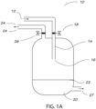
- Fig. 1A shows a typical pressure relief vessel, i.e. flash tank 10.
- High-pressure steam explosion is a process of rapid release of pressurized water or water-rich material 12 as shown by the arrow, normally conducted through a nozzle or an orifice. This process is known also as blowdown, explosive decompression, rapid depressurization, etc. and results in a rupture of the moist material and make it more accessible for subsequent processes, e.g. digestion or dewatering.
- a raw substrate is first compressed in a reactor, passes through the blowdown conduit 14 and then discharges from a nozzle 16 of the blowdown conduit 14 into the pressure relief vessel 10. The flow rate through the nozzle, i.e.
- the blowdown conduit includes also a valve 18, which according to the prior art would normally be located between the reactor (not shown) and the pressure relief vessel 10 ( Figure 1A ), whereas in a plant according to the present invention this would be in a position where the valve gate coincides with the tip or the end, of the blowdown conduit ( Figure 1B ).
- a vessel-inlet-nozzle/device i.e.
- an additional inlet device through which the discharged biomass is directed from the adjustable open area into the pressure relief vessel) made from a highly resistant/durable material, which is silicon carbide.
- substrate being discharged is collected as a liquid 20 in the flash tank and defines a liquid level 22.
- the flash tank 10 comprises also a conduit for allowing a flash stream 24 to exit with the aid of valve 26 and a conduit 27 allowing for the exit of the liquid 20 from the vessel.
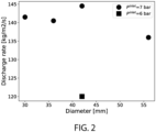
- Fig. 2 shows the results for different diameters of the nozzle.
- the circle and square symbols correspond to the inlet pressure of 7 and 6 bar, respectively.
- the X-axis shows the nozzle diameter in mm and the Y-axis shows the average flow rate in kg/m2/s.
- the outlet pressure was fixed at 2 bar.
- the experiments confirmed that the discharge rate is directly proportional to the cross-sectional area of the nozzle and decreases with the inlet pressure.
- the determination of the actual flow rate as e.g. ⁇ 140 kg/m2/s at an inlet pressure of 7 bar and an outlet pressure of 2 bar allows for the determination of the flow coefficient ( C V ), as a function of the cross-sectional area.
- a pipe made of 316 stainless steel with an outer diameter of 88 mm and wall thickness of 15 mm was installed directly after a blowdown nozzle made of hardened carbon steel.
- the inner diameter of the pipe downstream the nozzle was 58 mm while the blowdown nozzle had an inner diameter of 36 mm. This results in a distance of 11 mm from the opening of the blowdown nozzle to the pipe wall.
- the pressure and temperature on the entry side and discharge side of the blowdown nozzle was 7 bar and 165°C and 2 bar and 120°C, respectively. There were no visible or measurable signs of erosion in the blowdown nozzle or on the entry side of the nozzle after a total blowdown time of about 1000 hours.
- scaling can be mitigated by placing the blowdown nozzle or the part of a control valve used to regulate the discharge rate at the very end of pipework located inside a significantly larger pipe or inside a pressure vessel. Scaling will also occur in such a scenario, but formation of scaling is a relatively slow process. If the pressure relief vessel or piping downstream the control valve or restriction has a sufficiently large diameter, then scaling needs to be removed at reasonable time intervals such as during planned and scheduled annual maintenance stops.
- a mesh with smaller openings than the open area of a static nozzle or the smallest opening in an adjustable nozzle must be in place upstream of the the open area of a static nozzle or the smallest opening in an adjustable nozzle.
- the inlet pipe can face a surface at a distance smaller than the smallest opening size in a static or adjustable blowdown nozzle.
- the distance from the static part to the movable part can be as small as a few millimeters. If particles become stuck in the device, the movable part can be lifted to a position where the opening of the static part will have the smallest diameter of any section where substrate is present prior to the outlet. This will make it possible to dislodge stuck particles to reestablish flow through the nozzle by retracting the movable part. With this configuration, particles larger than those that can be passed through the blowdown nozzle remain in the reactor and are removed during scheduled maintenance stops.
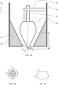
- the adjustable valve 28 at the outlet of the blowdown conduit 14 includes of a movable part 30 mounted on an adjustable rod 32 and a static part 34 which repeats the shape of the movable part 30 to block the fluid flow upon contact with the movable part 30.
- the static part 34 as shown by the hatched area is permanently fixed to wall of the blowdown conduit 14, this preferably being in form of a thick-walled pipe 36, while the movable part 30 can travel, preferably only vertically, by displacing the rod as shown by the arrows.
- the tip of the movable part 30 is a right circular cone with radius R and height H.
- the distance 2R corresponds to the opening at the outlet as also shown in the figure.
- the fluid passes through a cross-sectional area (S) formed between the cone and the static part. This can either be a circular ring created by rotating the segment AC (see Fig 5B ) around the vertical axis or a lateral surface of a newly formed cut cone with a slant height of AB (see Fig 5C ). Mathematically, this can be expressed as:
- Such arrangement helps to prevent development of flash steam prior to the outlet of the device.
- the slope of the movable part (cone) 30 ( tan ⁇ 1 R H ) is steeper compared to the static part 34. This ensures that the minimum open cross-sectional area always coincides with the circular ring ( S AC ) of the blowdown nozzle. As a result, the wear and tear on the static part is reduced with increasing of protrusion of the movable part 30 into the steam explosion zone, as also shown in Fig. 5A , and thereby imposing an extra load on the movable part 30.
- FIG. 6 Another embodiment according to the invention is shown by fitting a pipe with a close sliding fit inside a somewhat larger pipe where both pipes have holes that will overlap depending on the position of the pipe that can be rotated as also shown in in the figure. By rotating one pipe, the effective open area can be adjusted.
- the present invention thus encompasses a detailed arrangement of a valve to regulate the flow rate under the decompression. This is most relevant for a continuous THP plant but can also be used for batch process plants.
- a key feature of the device according to the present invention compared to the prior art is the improved resistivity to erosion and blockage, by the adjustable valve controlling the discharge rate being placed at the outlet end of the blowdown conduit (blowdown line).
Landscapes
- Life Sciences & Earth Sciences (AREA)
- Hydrology & Water Resources (AREA)
- Engineering & Computer Science (AREA)
- Environmental & Geological Engineering (AREA)
- Water Supply & Treatment (AREA)
- Chemical & Material Sciences (AREA)
- Organic Chemistry (AREA)
- Physics & Mathematics (AREA)
- Thermal Sciences (AREA)
- Processing Of Solid Wastes (AREA)
- Lift Valve (AREA)
- Disintegrating Or Milling (AREA)
Claims (14)
- Anlage zum Herstellen einer vorbehandelten Biomasse durch Unterziehen von Rohbiomasse einer thermischen Hydrolyse, wobei die Anlage Folgendes umfasst:- einen thermischen Hydrolysereaktor zum Herstellen von Biomasse unter Druck in Form von feuchtem Material (12), einschließlich abrasivem Material, das eine Partikelgröße von > 150 Mikron aufweist und mit 7 oder mehr auf der Mohs-Härteskala bewertet ist, und das einen trockenen Feststoffgehalt von über 5 % aufweist, wovon über 20 % flüchtige Feststoffe (volatile solids, VS) sind,- einen Druckentlastungsbehälter (10) in Fluidverbindung mit dem Reaktor zur Entlastung von Druck der unter Druck stehenden Biomasse und- eine Vorrichtung zum Entlasten des Drucks der Biomasse beim Eintreten des Druckentlastungsbehälters, umfassend eine oder mehrere Abschlämmleitungen (14) zum Transportieren der Biomasse in Form von feuchtem Material (12) von dem Reaktor zu dem Druckentlastungsbehälter (10) und zum Abgeben der Biomasse in Form von feuchtem Material (12) in den Druckentlastungsbehälter (10),wobei:- jede der einen oder der mehreren Abschlämmleitungen (14) an ihrem Auslass mit einem Ventil (28) versehen ist, das einen variablen Querschnitt aufweist, der einen regelbaren geöffneten Bereich (16) zum Regulieren der Abschlämmabgaberate der Biomasse in der Form von feuchtem Material (12) in den Druckentlastungsbehälter (10) bereitstellt, und das Ventil (28) so konstruiert ist, dass es sicherstellt, dass sich der kleinste Querschnitt/Öffnungsbereich der einen oder der mehreren Abschlämmleitungen (14) an dem Auslass der einen oder der mehreren Abschlämmleitungen (14) befindet,wobei die Anlage dadurch gekennzeichnet ist, dass die eine oder mehreren Abschlämmleitungen (14) eine der folgenden Ausgestaltungen aufweisen:(i) stromabwärts des Ventils (28) wird keine Rohrleitung bereitgestellt, sodass Expansion/Sprühung aufgrund von Entspannung innerhalb des Druckentlastungsbehälters (10) stattfindet, wobei entweder Opfermaterial stromabwärts des minimalen geöffneten Querschnitts, wo die Dampfexplosion stattfindet, bereitgestellt wird, oder eine Ablenkplatte bereitgestellt wird, auf die die aus dem Abschlämmleitungsventil (28) abgegebene Biomasse gerichtet wird,(ii) das Ventil (28) ist mit einer Behälter-Einlass-Düse/Vorrichtung ausgestattet, durch die die abgegebene Biomasse von dem regelbaren geöffneten Bereich in den Druckentlastungsbehälter (10) gerichtet wird, wobei Expansion/Sprühung aufgrund von Entspannung innerhalb der Behälter-Einlass-Düse/Vorrichtung stattfindet und die Behälter-Einlass-Düse/Vorrichtung aus einem sehr haltbaren Material mit hoher Erosionsbeständigkeit, nämlich Siliziumkarbid, hergestellt ist.
- Anlage nach Anspruch 1, wobei die Ventile (28), die an dem Auslass der einen oder der mehreren Abschlämmleitungen (14) angepasst sind, ein integraler Bestandteil der einen oder der mehreren Abschlämmleitungen (14) sind.
- Anlage nach einem der Ansprüche 1 oder 2, umfassend eine Vielzahl von Abschlämmleitungen (14), die jeweils mit Ventilen (28) an dem Auslass der Abschlämmleitungen (14) angepasst sind.
- Anlage nach einem der Ansprüche 1-3, wobei das eine oder die mehreren Ventile (28) in der Form einer Ventilanordnung angeordnet sind, umfassend:- ein Stützelement (38), das an einer Wand der Abschlämmleitung (14) befestigt ist,- eine verschiebbare Stange (32), die angepasst ist, um mit dem Stützelement zu kooperieren,- ein bewegliches Teil (30), das an der regelbaren Stange (32) montiert ist,- ein statisches Teil (34), das eine Form aufweist, die der des beweglichen Teils (30) entspricht, um den Strom der Biomasse in der Form von feuchtem Material (12) bei Berührung mit dem beweglichen Teil (30) zu blockieren.
- Anlage nach Anspruch 4, wobei der bewegliche Teil (30) ein Kegel ist, der eine Kegelneigung definiert, und die Form des statischen Teils (34), die der des beweglichen Teils (30) entspricht, eine Neigung definiert, die gleich oder höher als die Kegelneigung ist.
- Anlage nach Anspruch 4 oder 5, wobei der bewegliche Teil (30) aus einem Material mit hoher Erosionsbeständigkeit, nämlich Siliziumkarbid (silicon carbide, SiC), hergestellt ist.
- Anlage nach einem der Ansprüche 1-3, wobei eine oder mehrere der einen oder mehreren Abschlämmleitungen (14) eine erste Rohrleitung und eine zweite Rohrleitung umfassen, die gegenseitig drehbar sind, wobei die erste Rohrleitung mit einem engen Gleitsitz innerhalb der zweiten Rohrleitung versehen ist, wobei die erste und die zweite Rohrleitung Löcher/Öffnungen definieren, die sich in Abhängigkeit von der Drehung der Rohrleitung überlappen, um den regelbaren geöffneten Bereich (16) zu variieren.
- Anlage nach einem der Ansprüche 1-7, ferner umfassend ein Netz mit kleineren Öffnungen als der kleinsten Querschnitt/Öffnungsbereich des einen oder der mehreren regelbaren geöffneten Bereiche (16) an dem Auslass der einen oder der mehreren Abschlämmleitungen (14), wobei das Netz stromaufwärts von dem Auslass der einen oder der mehreren Abschlämmleitungen (14) angeordnet ist.
- Verfahren zur thermischen Hydrolyse von Rohbiomasse, umfassend- Unterziehen der betreffenden Rohbiomasse einer thermischen Hydrolyse, wodurch die Biomasse in Form eines feuchten Materials (12) unter Druck hergestellt wird,- Übertragen der Biomasse auf einen Druckentlastungsbehälter (10) zur Entlastung von Druck des feuchten Materials (12),dadurch gekennzeichnet, dass- die Biomasse in der Form von feuchtem Material (12) gebildet ist, das einen trockenen Feststoffgehalt von über 5 % aufweist, wovon über 20 % flüchtige Feststoffe (VS) sind, und dass sie abrasives Material beinhaltet, das eine Partikelgröße von > 150 Mikron aufweist und mit 7 oder mehr auf der Mohs-Härteskala bewertet ist,- die Übertragung der Biomasse auf den Druckentlastungsbehälter durch Verwendung einer Vorrichtung erzielt wird, umfassend eine oder mehrere Abschlämmleitungen (14) zum Transportieren der Biomasse in Form von feuchtem Material (12) von dem Reaktor zu dem Druckentlastungsbehälter (10) und zum Abgeben der Biomasse in Form von feuchtem Material (12) in den Druckentlastungsbehälter (10),- die eine oder die mehreren Abschlämmleitungen (14) an ihrem Auslass mit Ventilen (28) versehen sind, das einen variablen Querschnitt aufweist, der einen regelbaren geöffneten Bereich (16) zum a) Regulieren der Abschlämmabgaberate der Biomasse in der Form von feuchtem Material (12) in den Druckentlastungsbehälter (10) bereitstellt, und b) Bereitstellen des kleinsten Querschnitts/Öffnungsbereichs der einen oder der mehreren Abschlämmleitungen (14) an dem Auslass der einen oder der mehreren Abschlämmleitungen (14), und- die eine oder mehreren Abschlämmleitungen (14) eine der folgenden Ausgestaltungen aufweisen:(i) stromabwärts des Ventils (28) wird keine Rohrleitung bereitgestellt, sodass Expansion/Sprühung aufgrund von Entspannung innerhalb des Druckentlastungsbehälters (10) stattfindet, wobei entweder Opfermaterial stromabwärts des minimalen geöffneten Querschnitts, wo die Dampfexplosion stattfindet, bereitgestellt wird, oder eine Ablenkplatte bereitgestellt wird, auf die die aus dem Abschlämmleitungsventil (28) abgegebene Biomasse gerichtet wird,(ii) das Ventil (28) ist mit einer Behälter-Einlass-Düse/Vorrichtung ausgestattet, durch die die abgegebene Biomasse von dem regelbaren geöffneten Bereich in den Druckentlastungsbehälter (10) gerichtet wird, wobei Expansion/Sprühung aufgrund von Entspannung innerhalb der Behälter-Einlass-Düse/Vorrichtung stattfindet und die Behälter-Einlass-Düse/Vorrichtung aus einem sehr haltbaren Material mit hoher Erosionsbeständigkeit, nämlich Siliziumkarbid, hergestellt ist.
- Verfahren nach Anspruch 9, wobei die Ventile (28) auf eine oder mehrere Verschleißplatten, Verschleißvorrichtungen, Ablenkplatten oder ähnliche Stücke der Ausrüstung ausgerichtet sind.
- Verfahren nach einem der Ansprüche 9-10, wobei das eine oder die mehreren Ventile (28) in der Form einer Ventilanordnung angeordnet sind, umfassend:- ein Stützelement (38), das an einer Wand der Abschlämmleitung (14) befestigt ist,- eine verschiebbare Stange (32), die angepasst ist, um mit dem Stützelement (38) zu kooperieren,- ein bewegliches Teil (30), das an der regelbaren Stange (32) montiert ist,- ein statisches Teil (34), das eine Form aufweist, die der des beweglichen Teils (30) entspricht, um den Strom der Biomasse in der Form von feuchtem Material (12) bei Berührung mit dem beweglichen Teil (30) zu blockieren.
- Verfahren nach Anspruch 11, wobei der bewegliche Teil (30) ein Kegel ist, der eine Kegelneigung definiert, und die Form des statischen Teils (34), die der des beweglichen Teils (30) entspricht, eine Neigung definiert, die gleich oder höher als die Kegelneigung ist.
- Verfahren nach Anspruch 11 oder 12, wobei der bewegliche Teil (30) aus einem Material mit hoher Erosionsbeständigkeit, nämlich Siliziumkarbid (silicon carbide, SiC), hergestellt ist.
- Verfahren nach einem der Ansprüche 9-10, wobei eine oder mehrere der einen oder mehreren Abschlämmleitungen (14) eine erste Rohrleitung und eine zweite Rohrleitung umfassen, die gegenseitig drehbar sind, wobei die erste Rohrleitung mit einem engen Gleitsitz innerhalb der zweiten Rohrleitung versehen ist, wobei die erste und die zweite Rohrleitung Löcher/Öffnungen definieren, die sich in Abhängigkeit von der Drehung der Rohrleitung überlappen, um den regelbaren geöffneten Bereich (16) zu variieren.
Applications Claiming Priority (2)
| Application Number | Priority Date | Filing Date | Title |
|---|---|---|---|
| EP19192152 | 2019-08-16 | ||
| PCT/EP2020/072874 WO2021032623A1 (en) | 2019-08-16 | 2020-08-14 | Device for controlling thermal hydrolysis decompression and process plant comprising such device |
Publications (3)
| Publication Number | Publication Date |
|---|---|
| EP4013722A1 EP4013722A1 (de) | 2022-06-22 |
| EP4013722B1 true EP4013722B1 (de) | 2025-01-22 |
| EP4013722C0 EP4013722C0 (de) | 2025-01-22 |
Family
ID=67659128
Family Applications (1)
| Application Number | Title | Priority Date | Filing Date |
|---|---|---|---|
| EP20754262.2A Active EP4013722B1 (de) | 2019-08-16 | 2020-08-14 | Vorrichtung zur steuerung der thermischen hydrolysedekompression und prozessanlage mit solch einer vorrichtung |
Country Status (6)
| Country | Link |
|---|---|
| US (1) | US12492132B2 (de) |
| EP (1) | EP4013722B1 (de) |
| CN (1) | CN114466827B (de) |
| ES (1) | ES3017413T3 (de) |
| PL (1) | PL4013722T3 (de) |
| WO (1) | WO2021032623A1 (de) |
Families Citing this family (2)
| Publication number | Priority date | Publication date | Assignee | Title |
|---|---|---|---|---|
| CN117819639B (zh) * | 2024-03-05 | 2024-06-18 | 中城院(北京)环境科技股份有限公司 | 一种厨余垃圾废水处理设备 |
| US12234161B1 (en) | 2024-09-04 | 2025-02-25 | Zhongcheng Institute (Beijing) Environmental Technology Co., Ltd. | Kitchen waste wastewater treatment equipment |
Family Cites Families (18)
| Publication number | Priority date | Publication date | Assignee | Title |
|---|---|---|---|---|
| US5628830A (en) | 1979-03-23 | 1997-05-13 | The Regents Of The University Of California | Enzymatic hydrolysis of biomass material |
| NO300094B1 (no) | 1994-09-28 | 1997-04-07 | Cambi As | Fremgangsmate og anordning ved hydrolyse av organisk materiale under reduserende betingelser |
| NO310717B1 (no) | 1999-05-31 | 2001-08-20 | Cambi As | Fremgangsmate og anordning for kontinuerlig hydrolyse av avlopsvann |
| US20090053800A1 (en) | 2007-08-22 | 2009-02-26 | Julie Friend | Biomass Treatment Apparatus |
| NO331912B1 (no) | 2009-07-13 | 2012-04-30 | Cambi As | Dyseinnretning for trykkavlastning av materilaer inneholdende eroderende forbindelser |
| NO330122B1 (no) * | 2009-07-13 | 2011-02-21 | Cambi As | Fremgangsmate og anordning for termisk hydrolyse av biomasse og dampeksplosjon av biomasse |
| US9518358B2 (en) | 2011-02-17 | 2016-12-13 | Andritz Inc. | Assembly of nozzles and valves as discharge ports of a pressurized vessel and method for switching and replacing the nozzles and valves |
| US9103070B2 (en) | 2012-02-13 | 2015-08-11 | Andritz Inc. | Flash tank with adjustable inlet |
| NO335470B1 (no) * | 2013-02-07 | 2014-12-15 | Cambi Technology As | Fremgangsmåte for forbehandling av biomasse til energikonvertering |
| NO335177B1 (no) * | 2013-03-06 | 2014-10-13 | Cambi Technology As | Fremgangsmåte og anordning for termisk biologisk nedbryting og avvanning av biomasse |
| ES2538176B1 (es) | 2014-06-11 | 2015-10-05 | Te Consulting House 4 Plus, Sl | Procedimiento e instalación para la hidrólisis térmica de materia orgánica con bajos tiempos de residencia y sin bombas |
| US9738836B2 (en) * | 2014-08-28 | 2017-08-22 | Exxonmobil Research And Engineering Company | Fluid injection nozzle for fluid bed reactors |
| ES2692832T3 (es) * | 2014-10-29 | 2018-12-05 | Cambi Technology As | Método de tratamiento de biomasa y residuos orgánicos |
| PL3230463T5 (pl) * | 2014-12-09 | 2025-10-13 | Apalta Patents OÜ | Szybkie przetwarzanie wstępne |
| FR3053969B1 (fr) | 2016-07-18 | 2019-12-20 | IFP Energies Nouvelles | Procede de traitement de biomasse ligno-cellulosique par impregnation et explosion a la vapeur |
| CN108426069A (zh) | 2017-02-11 | 2018-08-21 | 何巨堂 | 用至少2个可动节流件组成的冲蚀料降压系统及设备 |
| US10443743B2 (en) | 2017-11-14 | 2019-10-15 | Brasscraft Manufacturing Company | Rotary plug valve |
| CN208762396U (zh) | 2018-08-29 | 2019-04-19 | 湖南军信环保股份有限公司 | 热水解闪蒸分离装置及热水解系统 |
-
2020
- 2020-08-14 US US17/635,149 patent/US12492132B2/en active Active
- 2020-08-14 EP EP20754262.2A patent/EP4013722B1/de active Active
- 2020-08-14 WO PCT/EP2020/072874 patent/WO2021032623A1/en not_active Ceased
- 2020-08-14 CN CN202080068523.3A patent/CN114466827B/zh active Active
- 2020-08-14 ES ES20754262T patent/ES3017413T3/es active Active
- 2020-08-14 PL PL20754262.2T patent/PL4013722T3/pl unknown
Also Published As
| Publication number | Publication date |
|---|---|
| WO2021032623A1 (en) | 2021-02-25 |
| CN114466827B (zh) | 2024-06-14 |
| EP4013722C0 (de) | 2025-01-22 |
| US20220274850A1 (en) | 2022-09-01 |
| PL4013722T3 (pl) | 2025-04-28 |
| EP4013722A1 (de) | 2022-06-22 |
| CN114466827A (zh) | 2022-05-10 |
| ES3017413T3 (en) | 2025-05-12 |
| US12492132B2 (en) | 2025-12-09 |
Similar Documents
| Publication | Publication Date | Title |
|---|---|---|
| EP4013722B1 (de) | Vorrichtung zur steuerung der thermischen hydrolysedekompression und prozessanlage mit solch einer vorrichtung | |
| RU2415818C1 (ru) | Способ получения альфа-полугидрата сульфата кальция из дигидрата сульфата кальция | |
| HK40076691B (en) | Device for controlling thermal hydrolysis decompression and process plant comprising such device | |
| HK40076691A (en) | Device for controlling thermal hydrolysis decompression and process plant comprising such device | |
| CN115703094A (zh) | 一种气液同轴自激共振腔式雾化喷射装置及其制备方法 | |
| CN86105182A (zh) | 固体燃料气化反应器用的渣滓排除装置 | |
| CN102465188B (zh) | 罐式冶金熔渣处理装置 | |
| CN107532378B (zh) | 具有可拆卸的内衬垫的排放阀 | |
| Avcu et al. | High-velocity air fuel coatings for steel for erosion-resistant applications | |
| CN209602574U (zh) | 一种inba高炉水渣处理装置 | |
| TW550293B (en) | Blast furnace granulated slag, fine aggregate prepared therefrom and method for producing them | |
| Jankovic et al. | Fine grinding in the Australian mining industry | |
| JP6826416B2 (ja) | 砂分離槽、取換え可能な多孔インサート装置および方法 | |
| WO2011006853A1 (en) | Exchangeable nozzle device for pressure relief of materials containing erosive compounds | |
| US20200001259A1 (en) | Sparge for a high-pressure vessel | |
| CN209348750U (zh) | 一种矿渣立磨选粉机主轴下部轴承水冷装置 | |
| KR930011926B1 (ko) | 고체연료 가스화 장치의 슬래그 제거 시스템 | |
| Kovalev et al. | Improving the efficiency of the automated process of drying flotation concentrate in a drum drying furnace | |
| CN207899559U (zh) | 胶性污泥破碎系统 | |
| RU2771973C1 (ru) | Спаргер для сосуда высокого давления | |
| CAPLAN | Fluid Flow, Slurry Systems and Pipelines | |
| CN108579980A (zh) | 胶性污泥破碎系统 | |
| CN106191349B (zh) | 一种炼铁工业废水在线综合使用系统及方法 | |
| Krivoborodov | Increasing the activity of cements during mechanical activation of raw materials | |
| CN203591707U (zh) | 一种提高固液快速溶出与分离的装置 |
Legal Events
| Date | Code | Title | Description |
|---|---|---|---|
| STAA | Information on the status of an ep patent application or granted ep patent |
Free format text: STATUS: UNKNOWN |
|
| STAA | Information on the status of an ep patent application or granted ep patent |
Free format text: STATUS: THE INTERNATIONAL PUBLICATION HAS BEEN MADE |
|
| PUAI | Public reference made under article 153(3) epc to a published international application that has entered the european phase |
Free format text: ORIGINAL CODE: 0009012 |
|
| STAA | Information on the status of an ep patent application or granted ep patent |
Free format text: STATUS: REQUEST FOR EXAMINATION WAS MADE |
|
| 17P | Request for examination filed |
Effective date: 20220315 |
|
| AK | Designated contracting states |
Kind code of ref document: A1 Designated state(s): AL AT BE BG CH CY CZ DE DK EE ES FI FR GB GR HR HU IE IS IT LI LT LU LV MC MK MT NL NO PL PT RO RS SE SI SK SM TR |
|
| DAV | Request for validation of the european patent (deleted) | ||
| DAX | Request for extension of the european patent (deleted) | ||
| REG | Reference to a national code |
Ref country code: HK Ref legal event code: DE Ref document number: 40076691 Country of ref document: HK |
|
| P01 | Opt-out of the competence of the unified patent court (upc) registered |
Effective date: 20230516 |
|
| STAA | Information on the status of an ep patent application or granted ep patent |
Free format text: STATUS: EXAMINATION IS IN PROGRESS |
|
| 17Q | First examination report despatched |
Effective date: 20231124 |
|
| GRAP | Despatch of communication of intention to grant a patent |
Free format text: ORIGINAL CODE: EPIDOSNIGR1 |
|
| STAA | Information on the status of an ep patent application or granted ep patent |
Free format text: STATUS: GRANT OF PATENT IS INTENDED |
|
| INTG | Intention to grant announced |
Effective date: 20240910 |
|
| GRAS | Grant fee paid |
Free format text: ORIGINAL CODE: EPIDOSNIGR3 |
|
| GRAA | (expected) grant |
Free format text: ORIGINAL CODE: 0009210 |
|
| STAA | Information on the status of an ep patent application or granted ep patent |
Free format text: STATUS: THE PATENT HAS BEEN GRANTED |
|
| AK | Designated contracting states |
Kind code of ref document: B1 Designated state(s): AL AT BE BG CH CY CZ DE DK EE ES FI FR GB GR HR HU IE IS IT LI LT LU LV MC MK MT NL NO PL PT RO RS SE SI SK SM TR |
|
| REG | Reference to a national code |
Ref country code: GB Ref legal event code: FG4D |
|
| REG | Reference to a national code |
Ref country code: CH Ref legal event code: EP |
|
| REG | Reference to a national code |
Ref country code: IE Ref legal event code: FG4D |
|
| REG | Reference to a national code |
Ref country code: DE Ref legal event code: R096 Ref document number: 602020045161 Country of ref document: DE |
|
| U01 | Request for unitary effect filed |
Effective date: 20250211 |
|
| P04 | Withdrawal of opt-out of the competence of the unified patent court (upc) registered |
Free format text: CASE NUMBER: APP_7824/2025 Effective date: 20250215 |
|
| U07 | Unitary effect registered |
Designated state(s): AT BE BG DE DK EE FI FR IT LT LU LV MT NL PT RO SE SI Effective date: 20250219 |
|
| REG | Reference to a national code |
Ref country code: ES Ref legal event code: FG2A Ref document number: 3017413 Country of ref document: ES Kind code of ref document: T3 Effective date: 20250512 |
|
| REG | Reference to a national code |
Ref country code: GR Ref legal event code: EP Ref document number: 20250400781 Country of ref document: GR Effective date: 20250514 |
|
| PG25 | Lapsed in a contracting state [announced via postgrant information from national office to epo] |
Ref country code: RS Free format text: LAPSE BECAUSE OF FAILURE TO SUBMIT A TRANSLATION OF THE DESCRIPTION OR TO PAY THE FEE WITHIN THE PRESCRIBED TIME-LIMIT Effective date: 20250422 |
|
| PG25 | Lapsed in a contracting state [announced via postgrant information from national office to epo] |
Ref country code: IS Free format text: LAPSE BECAUSE OF FAILURE TO SUBMIT A TRANSLATION OF THE DESCRIPTION OR TO PAY THE FEE WITHIN THE PRESCRIBED TIME-LIMIT Effective date: 20250522 |
|
| PG25 | Lapsed in a contracting state [announced via postgrant information from national office to epo] |
Ref country code: HR Free format text: LAPSE BECAUSE OF FAILURE TO SUBMIT A TRANSLATION OF THE DESCRIPTION OR TO PAY THE FEE WITHIN THE PRESCRIBED TIME-LIMIT Effective date: 20250122 |
|
| U20 | Renewal fee for the european patent with unitary effect paid |
Year of fee payment: 6 Effective date: 20250826 |
|
| PG25 | Lapsed in a contracting state [announced via postgrant information from national office to epo] |
Ref country code: SM Free format text: LAPSE BECAUSE OF FAILURE TO SUBMIT A TRANSLATION OF THE DESCRIPTION OR TO PAY THE FEE WITHIN THE PRESCRIBED TIME-LIMIT Effective date: 20250122 |
|
| PGFP | Annual fee paid to national office [announced via postgrant information from national office to epo] |
Ref country code: ES Payment date: 20250910 Year of fee payment: 6 |
|
| PGFP | Annual fee paid to national office [announced via postgrant information from national office to epo] |
Ref country code: NO Payment date: 20250829 Year of fee payment: 6 Ref country code: GR Payment date: 20250826 Year of fee payment: 6 |
|
| PGFP | Annual fee paid to national office [announced via postgrant information from national office to epo] |
Ref country code: TR Payment date: 20250807 Year of fee payment: 6 Ref country code: PL Payment date: 20250808 Year of fee payment: 6 |
|
| PGFP | Annual fee paid to national office [announced via postgrant information from national office to epo] |
Ref country code: GB Payment date: 20250826 Year of fee payment: 6 |
|
| PGFP | Annual fee paid to national office [announced via postgrant information from national office to epo] |
Ref country code: CH Payment date: 20250901 Year of fee payment: 6 |
|
| PG25 | Lapsed in a contracting state [announced via postgrant information from national office to epo] |
Ref country code: CZ Free format text: LAPSE BECAUSE OF FAILURE TO SUBMIT A TRANSLATION OF THE DESCRIPTION OR TO PAY THE FEE WITHIN THE PRESCRIBED TIME-LIMIT Effective date: 20250122 |
|
| PGFP | Annual fee paid to national office [announced via postgrant information from national office to epo] |
Ref country code: IE Payment date: 20250825 Year of fee payment: 6 |
|
| PG25 | Lapsed in a contracting state [announced via postgrant information from national office to epo] |
Ref country code: SK Free format text: LAPSE BECAUSE OF FAILURE TO SUBMIT A TRANSLATION OF THE DESCRIPTION OR TO PAY THE FEE WITHIN THE PRESCRIBED TIME-LIMIT Effective date: 20250122 |
|
| PLBE | No opposition filed within time limit |
Free format text: ORIGINAL CODE: 0009261 |
|
| STAA | Information on the status of an ep patent application or granted ep patent |
Free format text: STATUS: NO OPPOSITION FILED WITHIN TIME LIMIT |
|
| REG | Reference to a national code |
Ref country code: CH Ref legal event code: L10 Free format text: ST27 STATUS EVENT CODE: U-0-0-L10-L00 (AS PROVIDED BY THE NATIONAL OFFICE) Effective date: 20251203 |
|
| 26N | No opposition filed |
Effective date: 20251023 |