EP4013618B1 - Kühleinheit für eine druckmaschine und druckmaschine - Google Patents
Kühleinheit für eine druckmaschine und druckmaschine Download PDFInfo
- Publication number
- EP4013618B1 EP4013618B1 EP20742276.7A EP20742276A EP4013618B1 EP 4013618 B1 EP4013618 B1 EP 4013618B1 EP 20742276 A EP20742276 A EP 20742276A EP 4013618 B1 EP4013618 B1 EP 4013618B1
- Authority
- EP
- European Patent Office
- Prior art keywords
- unit
- dryer
- coolant circuit
- printing
- printing machine
- Prior art date
- Legal status (The legal status is an assumption and is not a legal conclusion. Google has not performed a legal analysis and makes no representation as to the accuracy of the status listed.)
- Active
Links
Images

Classifications
-
- B—PERFORMING OPERATIONS; TRANSPORTING
- B41—PRINTING; LINING MACHINES; TYPEWRITERS; STAMPS
- B41F—PRINTING MACHINES OR PRESSES
- B41F23/00—Devices for treating the surfaces of sheets, webs, or other articles in connection with printing
- B41F23/04—Devices for treating the surfaces of sheets, webs, or other articles in connection with printing by heat drying, by cooling, by applying powders
-
- B—PERFORMING OPERATIONS; TRANSPORTING
- B41—PRINTING; LINING MACHINES; TYPEWRITERS; STAMPS
- B41F—PRINTING MACHINES OR PRESSES
- B41F23/00—Devices for treating the surfaces of sheets, webs, or other articles in connection with printing
- B41F23/04—Devices for treating the surfaces of sheets, webs, or other articles in connection with printing by heat drying, by cooling, by applying powders
- B41F23/0403—Drying webs
-
- B—PERFORMING OPERATIONS; TRANSPORTING
- B41—PRINTING; LINING MACHINES; TYPEWRITERS; STAMPS
- B41F—PRINTING MACHINES OR PRESSES
- B41F23/00—Devices for treating the surfaces of sheets, webs, or other articles in connection with printing
- B41F23/04—Devices for treating the surfaces of sheets, webs, or other articles in connection with printing by heat drying, by cooling, by applying powders
- B41F23/044—Drying sheets, e.g. between two printing stations
- B41F23/0443—Drying sheets, e.g. between two printing stations after printing
-
- B—PERFORMING OPERATIONS; TRANSPORTING
- B41—PRINTING; LINING MACHINES; TYPEWRITERS; STAMPS
- B41F—PRINTING MACHINES OR PRESSES
- B41F31/00—Inking arrangements or devices
- B41F31/002—Heating or cooling of ink or ink rollers
Definitions
- the invention relates to a refrigeration unit for a printing machine, especially for a flexographic printing machine.
- the invention relates to a printing machine, especially a flexographic printing machine.
- Printing machines especially flexographic printing machines, and refrigeration units to be used in connection with such machines are known in the art.
- a flexographic printing machine is a printing machine which uses the principle of flexography for printing on a substrate or support material.
- the key element of such a machine is a rubber or polymer plate on which a positive mirrored master of the required image is provided as a 3D relief.
- the image areas are raised with respect to the non-image areas on the rubber or polymer plate.
- the plate is mounted on a so-called plate cylinder.
- ink is transferred from an ink reservoir to the so-called anilox roller or ceramic roller whose texture can absorb a specific amount of ink.
- the anilox roller then applies the ink to the printing plate in a uniform thickness.
- the actual printing process takes place with the substrate being held between the printing plate and the impression cylinder. In this situation the image is transferred from the printing plate to the substrate.
- a scraper or doctor blade may be used in order to remove excessive ink from the anilox roller before inking the printing plate.
- Flexographic printing machines are widely used for printing on almost any type of substrate, e.g. plastics, metal, and paper. It is especially common in the packaging industry. Very often the terms “flexography” or “flexographic” are abbreviated to "flexo”.
- the impression drum which may also be termed a central impression drum, is connected to a refrigeration unit in order to cool the impression drum and the substrate supported thereon.
- heat is transferred from the impression drum to an outdoor heat exchanger via a water circuit.
- the impression drum is heat conductively connected to a water circuit, which absorbs heat in the area of the impression drum and releases the heat to an outdoor environment.
- an outdoor heat exchanger or refrigeration unit is used in order to avoid overheating of the room where the flexographic printing machine is located.
- the web of substrate or support material has to be cooled after is has travelled through the main dryer of the printing machine. Consequently, another refrigeration unit is placed after the main dryer, when regarded in the direction of travel of the web of substrate or support material.
- This refrigeration unit is also connected to an outdoor heat exchanger or outdoor refrigeration unit via a water circuit.
- the outdoor heat exchanger or refrigeration unit for cooling the central impression drum and the outdoor heat exchanger or refrigeration unit for cooling the web of substrate may be the same.
- DE 10 2008 027 473 A1 discloses a cooling system for e.g. offset printing machine which has an adsorption-cooling machine connected with cold user unit of printing machine and with a heat generator to provide cooling capacity during operation of printing machine.
- the disclosed system has an adsorption-cooling machine designed in such a way that the adsorption-cooling machine is connectable with a cold user unit of a printing machine and with a heat generator to provide a cooling capacity (Qo) during operation of the printing machine.
- the adsorption-cooling machine has an adsorber and/or a condenser that are thermally coupled with an external cooling device.
- the heat generator is thermally coupled with a desorber via a heat exchanger.
- US 2004 0040459A1 relates to a method for supplying forced draught/compressed air and drying air to a printing press, whereby the vacuum pumps or compressors required to supply said forced draught/compressed air are arranged together in a room with a separate air supply.
- the aim of the invention is to homogenise and if possible even condition air, in particular, process air for the printing press, whilst avoiding additional operating costs.
- the cooling air for the vacuum pumps or compressors is substantially conducted in a circuit, the heated exhaust air of the vacuum pumps and the heated cooling air of the vacuum pumps and compressors is cooled in a heat exchanger and is used to heat drying air that has been separated for this purpose.
- WO 2009/059787 A2 discloses an arrangement on a printing machine, comprising at least one low-temperature (NT) control point, at least one medium-temperature (MT) control point, and at least one high-temperature (HT) control point which are disposed in a low-temperature zone (NT zone), a medium-temperature zone (MT zone), and at least one high-temperature zone (HT zone) of a printing machine and are designed such that the NT zone can be controlled to a low temperature by means of the NT control point, the MT zone can be controlled to a medium temperature by means of the MT control point, and the HT zone can be controlled to a high temperature by means of the HT control point.
- NT zone low-temperature zone
- MT zone medium-temperature zone
- HT zone high-temperature zone
- the low temperature in the printing machine is lower than the medium temperature, and the medium temperature is lower than the high temperature.
- the arrangement further comprises a low-temperature (NT) control device and a high-temperature (HT) control device.
- the temperature at the MT control point can be controlled by means of both the NT control device and the HT control device.
- refrigeration units shall especially be simple to install and efficient in operation.
- a refrigeration unit for a printing machine especially for a flexographic printing machine, comprising a dryer interface connectable to a dryer unit of the printing machine in a heat conductive manner and a print interface connectable to a printing unit of the printing machine in a heat conductive manner, wherein the refrigeration unit is adapted to transfer heat from the print interface to the dryer interface, and wherein the heat transfer from the print interface to the dryer interface is realized by means of a single coolant circuit.
- the basic idea of the invention is to make effective use of the excessive heat, which needs to be eliminated from the printing unit or printing press. Consequently, the overall energy consumption of a flexographic printing machine equipped with a refrigeration unit according to the invention may be reduced.
- the excessive heat is used internally in the printing machine.
- the refrigeration unit comprises a coolant circuit having a first coolant circuit portion being attributed to the print interface and being positionable in the printing unit or adjacent to the printing unit, wherein the first coolant circuit portion is adapted for absorbing heat originating from the printing unit, and having a second coolant circuit portion being attributed to the dryer interface and being positionable in the dryer unit or adjacent to the dryer unit, wherein the second coolant circuit portion is adapted for delivering heat to the dryer unit.
- the first coolant portion is preferably positioned above the printing unit.
- the use of a coolant circuit makes the heat transfer from the printing unit to the dryer unit both reliable and efficient.
- the dimensioning of the coolant circuit may be adapted to the amount of heat to be transferred. Consequently, sufficient cooling of the printing unit is ensured.
- a coolant circuit may be easily adapted to available installation space and is relatively compact.
- the first coolant circuit portion comprises an evaporator adapted to evaporate coolant
- the second coolant circuit portion comprises a condenser adapted to condense coolant
- the coolant circuit further comprises a compressor being positioned between the first coolant circuit portion and the second coolant circuit portion, when regarded in the sense of coolant flow
- the coolant circuit additionally comprises an expansion valve being positioned between the second coolant circuit portion and the first coolant circuit portion, when regarded in the sense of coolant flow.
- the refrigeration unit comprises at least one ventilation unit positioned adjacent to the second coolant circuit portion, wherein the ventilation unit is adapted to create an air flow in the area of the second coolant circuit portion.
- the air flow may be connected to the air flow used in a dryer unit.
- the air flow created in the refrigeration unit may be the same air flow as is used for drying.
- the ventilation unit creates a so-called forced convection, which increases the heat transfer from the second coolant circuit portion to the air surrounding it. Consequently, the heat transfer capacity of the refrigeration unit is increased.
- a printing machine especially a flexographic printing machine, comprising a printing unit adapted for printing on a web of carrier material, a dryer unit being adapted for drying printed web of carrier material, and a refrigeration unit according to the invention, wherein the refrigeration unit is heat conductively connected to the dryer unit via the dryer interface, and wherein the refrigeration unit is heat conductively connected to the printing unit via the print interface. Consequently, the heat to be led away from the printing unit is kept internal to the printing machine and is provided to the dryer unit where it is used for drying the printed web.
- the printing machines operates in an energy efficient and cost efficient manner. Furthermore, an outdoor heat exchanger and the corresponding tubing is not necessary any more.
- the carrier material may be any material suitable as a substrate for flexographic printing machines, e.g. paper, cardboard, plastics, metal.
- the first coolant circuit portion is at least partially located inside a printing drum or adjacent to the printing drum.
- at least partially is to be understood in that at least a portion of the coolant circuit is located inside the printing drum. Consequently, the excessive heat on the printing drum may be led away in an efficient and reliable manner.
- the dryer unit may comprise a main dryer adapted for drying printed web of carrier material after the application of one or more inks of different colors.
- a main dryer is a dryer which dries the web after inks of all relevant colors have been applied thereto.
- Such a dryer is positioned after the printing unit, when regarded in the moving direction of the web.
- the dryer unit may comprise an intracolor dryer adapted for drying printed web of carrier material between the application of inks of different colors.
- Intracolor dryers usually are provided between the different ink application units of a printing unit. They serve the purpose of drying ink of one color before ink of another color is applied to the web.
- the dryer unit comprises a central ventilation system, wherein the heat from the printing unit is transferred to the central ventilation system.
- the central ventilation system may supply different kinds of dryers with warm air. For example, one or more intracolor dryers and one or more main dryers may be supplied with air by the central ventilation system.
- the refrigeration unit is connected to the dryer unit via an air conduit.
- the air conduit may also be designated a tunnel.
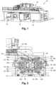
- Figure 1 shows a printing machine 10, which is a flexographic printing machine in the examples shown.
- It comprises a web feeding unit 12, where a web of carrier material may be stored before the printing process takes place, a printing unit 14 adapted for printing on the web of carrier material, and a storage unit 16, where printed web is stored after the printing process.
- the printing machine 10 also has a dryer unit 18, which comprises a main dryer 18a adapted for drying printed web of carrier material after the printing process.
- the printing unit 14 comprises a central impression drum 20, which is coupled to eight ink application units 22a, 22b, 22c, 22d, 22e, 22f, 22g, 22h, each of which is adapted to apply an ink of a different color to the web 24. Consequently, the flexographic printing machine 10 may be termed an eight color printing machine.
- intracolor dryer 18b is provided, which is part of the dryer unit 18.
- These intracolor dryers 18b are adapted for drying printed web of carrier material between the application of inks of different colors.
- the ink applied to the web 24 by the ink application unit 22a is dried by an intracolor dryer 18b before ink of a different color is applied to the web 24 by the ink application unit 22b and so on.
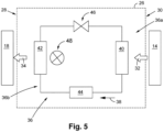
- the flexographic printing machine 10 also comprises a refrigeration unit 26 which is heat conductively connected to the dryer unit 18 via a dryer interface 28, and which is heat conductively connected to the printing unit 14 via a print interface 30 (cf. Figure 5 ).
- the refrigeration unit 26 is adapted to transfer heat from the print interface 30 to the dryer interface 28.
- the refrigeration unit 26 is adapted to extract heat from the printing unit 14, i.e. it is adapted to cool the printing unit 14, and supply the heat to the dryer unit 18, where it is used as process heat.
- the refrigeration unit 26 comprises a coolant circuit 36, wherein a flow direction of coolant is indicated by arrow 38.
- the coolant circuit 36 has a first coolant circuit portion 36a which is attributed to the print interface 30 and comprises an evaporator 40 adapted to evaporate the coolant.
- the first coolant circuit portion 36a is positioned adjacent to the printing unit 14. Alternatively, the first coolant circuit portion 36a is at least partially located inside the printing drum 20 or adjacent to the printing drum 20.
- the first coolant circuit portion 36a is adapted for absorbing heat 32 originating from the printing unit 14 and uses this heat 32 for evaporating the coolant.
- the coolant circuit 36 also has a second coolant circuit portion 36b which is attributed to the dryer interface 28 and comprises a condenser 42 adapted to condense coolant.
- the second coolant circuit portion 36b is positioned adjacent to the dryer unit 18.
- the second coolant circuit portion 36b is adapted for delivering heat 34 to the dryer unit 18 by condensing coolant.
- the coolant circuit is completed by a compressor 44 being positioned between the first coolant circuit portion 36a and the second coolant circuit portion 36b, when regarded in the sense of coolant flow 38.
- the compressor 44 is interposed between the evaporator 40 and the condenser 42.
- the coolant circuit 36 comprises an expansion valve 46 being positioned between the second coolant circuit portion 36b and the first coolant circuit portion 36a, when regarded in the sense of coolant flow 38.
- the refrigeration unit 26 comprises a ventilation unit 48 positioned adjacent to the second coolant circuit portion 36b.
- the ventilation unit 48 is adapted to create an air flow in the area of the second coolant circuit portion 36b, which enhances heat transfer from the coolant to the dryer unit 18.
- the air flow created by the ventilation unit 48 may be directly fed to the dryer unit 18.
- the dryer unit 18 may also comprise a central ventilation system 18c, wherein the heat 34 originating from the printing unit 14 is transferred to the central ventilation system 18c.
- the ventilation system 18c may supply the intracolor dryers 18b with heated air via conduits 18d and the main dryer 18a via conduits 18e.
- the coolant circuit 36 may use a hydrocarbon coolant, e.g. propane or butane.
- a hydrocarbon coolant e.g. propane or butane.
- the refrigeration unit 26 operates as follows.
- Coolant is evaporated in the evaporator 40 by heat 32 originating from the printing unit 14.
- gasified coolant is fed to the condenser 42 via the compressor 44, where it is condensed, i.e. the coolant is liquefied.
- the heat 34 resulting from the condensation process is fed to the dryer unit, especially to a central ventilation system 18c thereof. This process is assisted by the ventilation unit 48.
Landscapes
- Engineering & Computer Science (AREA)
- Mechanical Engineering (AREA)
- Supply, Installation And Extraction Of Printed Sheets Or Plates (AREA)
Claims (10)
- Kühleinheit (26) für eine Druckmaschine (10), insbesondere für eine Flexodruckmaschine, umfassendeine Trocknerschnittstelle (28), die auf eine wärmeleitende Weise mit einer Trocknereinheit (18) der Druckmaschine (10) verbindbar ist, undeine Druckschnittstelle (30), die auf eine wärmeleitende Weise mit einer Druckeinheit (14) der Druckmaschine (10) verbindbar ist,wobei die Kühleinheit (26) angepasst ist, um Wärme (32, 34) von der Druckschnittstelle (30) an die Trocknerschnittstelle (28) zu übertragen,und wobei die Wärmeübertragung von der Druckschnittstelle (30) an die Trocknerschnittstelle (28) mittels eines einzigen Kühlmittelkreislaufs realisiert wird.
- Kühleinheit (26) nach Anspruch 1, dadurch gekennzeichnet, dass die Kühleinheit (26) einen Kühlmittelkreislauf (36) umfasst,der einen ersten Kühlmittelkreislaufabschnitt (36a) aufweist, der der Druckschnittstelle (30) zugeordnet ist und in der Druckeinheit (14) oder neben der Druckeinheit (14) positionierbar ist, wobei der erste Kühlmittelkreislaufabschnitt (36a) zum Absorbieren von von der Druckeinheit (14) ausgehenden Wärme (32) angepasst ist, undder einen zweiten Kühlmittelkreislaufabschnitt (36b) aufweist, der der Trocknerschnittstelle (28) zugeordnet ist und in der Trocknereinheit (18) oder neben der Trocknereinheit (18) positionierbar ist, wobei der zweite Kühlmittelkreislaufabschnitt (36b) zum Abgeben von Wärme (34) an die Trocknereinheit (18) angepasst ist.
- Kühleinheit (26) nach Anspruch 2, dadurch gekennzeichnet, dassder erste Kühlmittelkreislaufabschnitt (36a) einen Verdampfer (40) umfasst, der zum Verdampfen von Kühlmittel angepasst ist, undder zweite Kühlmittelkreislaufabschnitt (36b) einen Kondensator (42) umfasst, der zum Kondensieren von Kühlmittel angepasst ist,wobei der Kühlmittelkreislauf (36) weiter einen Kompressor (44) umfasst, der, wenn in Richtung des Kühlmittelstroms betrachtet, zwischen dem ersten Kühlmittelkreislaufabschnitt (36a) und dem zweiten Kühlmittelkreislaufabschnitt (36b) positioniert ist, undwobei der Kühlmittelkreislauf (36) weiter ein Expansionsventil (46) umfasst, das, wenn in Richtung des Kühlmittelstroms betrachtet, zwischen dem zweiten Kühlmittelkreislaufabschnitt (36b) und dem ersten Kühlmittelkreislaufabschnitt (36a) positioniert ist.
- Kühleinheit (26) nach Anspruch 2 oder Anspruch 3, dadurch gekennzeichnet, dass die Kühleinheit (26) mindestens eine Belüftungseinheit (48) umfasst, die neben dem zweiten Kühlmittelkreislaufabschnitt (36b) positioniert ist, wobei die Belüftungseinheit (48) dazu angepasst ist, in dem Bereich des zweiten Kühlmittelkreislaufabschnitts (36b) einen Luftstrom zu erzeugen.
- Druckmaschine (10), insbesondere Flexodruckmaschine, umfassendeine Druckeinheit (14), die zum Bedrucken einer Bahn (24) aus Trägermaterial angepasst ist,eine Trocknereinheit (18), die zum Trocknen einer bedruckten Bahn (24) aus Trägermaterial angepasst ist, undeine Kühleinheit (26) nach einem der vorstehenden Ansprüche,wobei die Kühleinheit (26) über die Trocknerschnittstelle (28) wärmeleitend mit der Trocknereinheit (18) verbunden ist undwobei die Kühleinheit (26) über die Druckschnittstelle (30) wärmeleitend mit der Druckeinheit (14) verbunden ist.
- Druckmaschine (10) nach Anspruch 5, dadurch gekennzeichnet, dass der erste Kühlmittelkreislaufabschnitt (36a) mindestens teilweise innerhalb einer Drucktrommel (20) oder neben der Drucktrommel (20) angeordnet ist.
- Druckmaschine (10) nach Anspruch 5 oder Anspruch 6, dadurch gekennzeichnet, dass die Trocknereinheit (18) einen Haupttrockner (18a) umfasst, der zum Trocknen der bedruckten Bahn (24) aus Trägermaterial nach dem Aufbringen einer oder mehrerer Tinten unterschiedlicher Farbe angepasst ist.
- Druckmaschine (10) nach einem der Ansprüche 5 bis 7, dadurch gekennzeichnet, dass die Trocknereinheit (18) einen Intrafarbtrockner (18b) umfasst, der zum Trocknen der bedruckten Bahn (24) aus Trägermaterial zwischen dem Aufbringen von Tinten unterschiedlicher Farben angepasst ist.
- Druckmaschine (10) nach einem der Ansprüche 5 bis 8, dadurch gekennzeichnet, dass die Trocknereinheit (18) ein zentrales Belüftungssystem (18c) umfasst, wobei die Wärme von der Druckeinheit (14) an das zentrale Belüftungssystem (18c) übertragen wird.
- Druckmaschine (10) nach einem der Ansprüche 5 bis 9, dadurch gekennzeichnet, dass die Kühleinheit (26) über eine Luftleitung (18d, 18e) mit der Trocknereinheit (18) verbunden ist.
Applications Claiming Priority (2)
| Application Number | Priority Date | Filing Date | Title |
|---|---|---|---|
| EP19020477 | 2019-08-15 | ||
| PCT/EP2020/070699 WO2021028177A1 (en) | 2019-08-15 | 2020-07-22 | Refrigation unit for a printing machine and printing machine |
Publications (2)
| Publication Number | Publication Date |
|---|---|
| EP4013618A1 EP4013618A1 (de) | 2022-06-22 |
| EP4013618B1 true EP4013618B1 (de) | 2024-10-09 |
Family
ID=67659182
Family Applications (1)
| Application Number | Title | Priority Date | Filing Date |
|---|---|---|---|
| EP20742276.7A Active EP4013618B1 (de) | 2019-08-15 | 2020-07-22 | Kühleinheit für eine druckmaschine und druckmaschine |
Country Status (4)
| Country | Link |
|---|---|
| US (1) | US11938716B2 (de) |
| EP (1) | EP4013618B1 (de) |
| ES (1) | ES2992097T3 (de) |
| WO (1) | WO2021028177A1 (de) |
Family Cites Families (9)
| Publication number | Priority date | Publication date | Assignee | Title |
|---|---|---|---|---|
| DE10190901D2 (de) | 2000-03-16 | 2005-09-15 | Becker Kg Gebr | Verfahren und Vorrichtung zur Nutzung bei einer Saug- /Druckluftversorgung an einer Druckmaschine anfallenden Abwärme |
| DE10316860A1 (de) * | 2003-04-11 | 2004-10-21 | Rainer Olbert | Kühl- und Temperieranlage für eine Druckmaschine |
| DE102005016296B4 (de) * | 2005-04-08 | 2010-04-08 | OCé PRINTING SYSTEMS GMBH | Drucker oder Kopierer mit einer Kältemaschine zum Erzeugen von Kälte |
| DE102007053080A1 (de) | 2007-11-07 | 2009-05-20 | Technotrans Ag | Temperiersystem für Druckmaschinen mit mehreren Temperaturniveaus |
| DE102008027473B4 (de) | 2008-06-09 | 2012-10-04 | Technotrans Ag | Druckmaschinen-Kühlsystem |
| CN101737866A (zh) * | 2009-11-28 | 2010-06-16 | 杭州吴泰印刷包装机械有限公司 | 机组式凹版印刷机专用空气调节装置 |
| JP5751857B2 (ja) * | 2011-02-22 | 2015-07-22 | キヤノン株式会社 | 記録装置 |
| CN102653166B (zh) * | 2012-05-24 | 2015-07-08 | 赵智民 | 一种凹版印刷机 |
| CN103481659B (zh) * | 2013-09-17 | 2016-04-27 | 广东芬尼克兹节能设备有限公司 | 高效节能的印刷烘干机 |
-
2020
- 2020-07-22 EP EP20742276.7A patent/EP4013618B1/de active Active
- 2020-07-22 ES ES20742276T patent/ES2992097T3/es active Active
- 2020-07-22 US US17/633,860 patent/US11938716B2/en active Active
- 2020-07-22 WO PCT/EP2020/070699 patent/WO2021028177A1/en not_active Ceased
Also Published As
| Publication number | Publication date |
|---|---|
| EP4013618A1 (de) | 2022-06-22 |
| US11938716B2 (en) | 2024-03-26 |
| ES2992097T3 (es) | 2024-12-09 |
| US20220396068A1 (en) | 2022-12-15 |
| WO2021028177A1 (en) | 2021-02-18 |
Similar Documents
| Publication | Publication Date | Title |
|---|---|---|
| JP2877705B2 (ja) | 無水オフセット印刷のための印刷機械 | |
| EP2032363B1 (de) | Flexodruckmaschine mit einer trocknungs-, desikkations-, polymerisations- und/oder heizvorrichtung für den mit tinte benetzten streifen | |
| US8166877B2 (en) | Printing press having a dryer device for varnished sheets | |
| JP2752051B2 (ja) | 印刷機における温度調整装置 | |
| US6892642B2 (en) | Device and method for cooling a material web | |
| US8327762B2 (en) | Printing presses having one or more printing units embodied as printing towers for double-sided multicolor printing, and devices for controlling the temperature of components of one or more of the printing units | |
| US20110088879A1 (en) | Temperature Control System for Printing Machines Having Several Temperature Levels | |
| JPH0722991B2 (ja) | 乾式オフセット印刷用版胴をめぐって装着された版のための温度調節器 | |
| US2260364A (en) | Ink distribution system | |
| US11938716B2 (en) | Refrigeration unit for a printing machine and printing machine | |
| EP1710079B1 (de) | Druckmaschine mit Temperiervorrichtung | |
| CN102653166A (zh) | 一种凹版印刷机及其节能方法 | |
| US6571711B1 (en) | Print cylinder cooling system | |
| JP2005335383A (ja) | 処理機械の胴のための直結駆動装置 | |
| FI20185475A1 (fi) | Ilmankäsittelykoneikko, menetelmä ilmankäsittelykoneikon käyttämiseksi ja menetelmä ilmankäsittelykoneikon uudistamiseksi | |
| US20110162545A1 (en) | Printing unit, and devices and methods for controlling the temperature of a printing unit | |
| US7318378B2 (en) | Temperature control method and printing machine | |
| CN202608235U (zh) | 一种凹版印刷机 | |
| JP2010228368A (ja) | 湿し装置、湿し装置の結露滴下防止方法およびオフセット印刷機 | |
| CN104108244B (zh) | 一种用于宽幅数码印花涤纶墙布的加热装置 | |
| US20070266872A1 (en) | Apparatus for drying sheets in a sheet-fed printing press and sheet-fed printing press having the apparatus | |
| KR200388396Y1 (ko) | 윤전기의 폐열회수장치 | |
| US2110302A (en) | Impression cylinder for printing machines | |
| JP2003222454A (ja) | 冷水・温水循環装置 | |
| FI124588B (fi) | Menetelmä ja järjestely paperikoneen kuivatusosassa paperirainan kuivaamiseksi |
Legal Events
| Date | Code | Title | Description |
|---|---|---|---|
| STAA | Information on the status of an ep patent application or granted ep patent |
Free format text: STATUS: UNKNOWN |
|
| STAA | Information on the status of an ep patent application or granted ep patent |
Free format text: STATUS: THE INTERNATIONAL PUBLICATION HAS BEEN MADE |
|
| PUAI | Public reference made under article 153(3) epc to a published international application that has entered the european phase |
Free format text: ORIGINAL CODE: 0009012 |
|
| STAA | Information on the status of an ep patent application or granted ep patent |
Free format text: STATUS: REQUEST FOR EXAMINATION WAS MADE |
|
| 17P | Request for examination filed |
Effective date: 20220202 |
|
| AK | Designated contracting states |
Kind code of ref document: A1 Designated state(s): AL AT BE BG CH CY CZ DE DK EE ES FI FR GB GR HR HU IE IS IT LI LT LU LV MC MK MT NL NO PL PT RO RS SE SI SK SM TR |
|
| DAV | Request for validation of the european patent (deleted) | ||
| DAX | Request for extension of the european patent (deleted) | ||
| GRAP | Despatch of communication of intention to grant a patent |
Free format text: ORIGINAL CODE: EPIDOSNIGR1 |
|
| STAA | Information on the status of an ep patent application or granted ep patent |
Free format text: STATUS: GRANT OF PATENT IS INTENDED |
|
| GRAS | Grant fee paid |
Free format text: ORIGINAL CODE: EPIDOSNIGR3 |
|
| INTG | Intention to grant announced |
Effective date: 20240801 |
|
| GRAA | (expected) grant |
Free format text: ORIGINAL CODE: 0009210 |
|
| STAA | Information on the status of an ep patent application or granted ep patent |
Free format text: STATUS: THE PATENT HAS BEEN GRANTED |
|
| AK | Designated contracting states |
Kind code of ref document: B1 Designated state(s): AL AT BE BG CH CY CZ DE DK EE ES FI FR GB GR HR HU IE IS IT LI LT LU LV MC MK MT NL NO PL PT RO RS SE SI SK SM TR |
|
| REG | Reference to a national code |
Ref country code: CH Ref legal event code: EP |
|
| REG | Reference to a national code |
Ref country code: DE Ref legal event code: R096 Ref document number: 602020039092 Country of ref document: DE |
|
| REG | Reference to a national code |
Ref country code: IE Ref legal event code: FG4D |
|
| REG | Reference to a national code |
Ref country code: ES Ref legal event code: FG2A Ref document number: 2992097 Country of ref document: ES Kind code of ref document: T3 Effective date: 20241209 |
|
| REG | Reference to a national code |
Ref country code: LT Ref legal event code: MG9D |
|
| REG | Reference to a national code |
Ref country code: NL Ref legal event code: MP Effective date: 20241009 |
|
| REG | Reference to a national code |
Ref country code: AT Ref legal event code: MK05 Ref document number: 1730181 Country of ref document: AT Kind code of ref document: T Effective date: 20241009 |
|
| PG25 | Lapsed in a contracting state [announced via postgrant information from national office to epo] |
Ref country code: NL Free format text: LAPSE BECAUSE OF FAILURE TO SUBMIT A TRANSLATION OF THE DESCRIPTION OR TO PAY THE FEE WITHIN THE PRESCRIBED TIME-LIMIT Effective date: 20241009 |
|
| PG25 | Lapsed in a contracting state [announced via postgrant information from national office to epo] |
Ref country code: NL Free format text: LAPSE BECAUSE OF FAILURE TO SUBMIT A TRANSLATION OF THE DESCRIPTION OR TO PAY THE FEE WITHIN THE PRESCRIBED TIME-LIMIT Effective date: 20241009 |
|
| PG25 | Lapsed in a contracting state [announced via postgrant information from national office to epo] |
Ref country code: IS Free format text: LAPSE BECAUSE OF FAILURE TO SUBMIT A TRANSLATION OF THE DESCRIPTION OR TO PAY THE FEE WITHIN THE PRESCRIBED TIME-LIMIT Effective date: 20250209 Ref country code: HR Free format text: LAPSE BECAUSE OF FAILURE TO SUBMIT A TRANSLATION OF THE DESCRIPTION OR TO PAY THE FEE WITHIN THE PRESCRIBED TIME-LIMIT Effective date: 20241009 Ref country code: PT Free format text: LAPSE BECAUSE OF FAILURE TO SUBMIT A TRANSLATION OF THE DESCRIPTION OR TO PAY THE FEE WITHIN THE PRESCRIBED TIME-LIMIT Effective date: 20250210 |
|
| PG25 | Lapsed in a contracting state [announced via postgrant information from national office to epo] |
Ref country code: FI Free format text: LAPSE BECAUSE OF FAILURE TO SUBMIT A TRANSLATION OF THE DESCRIPTION OR TO PAY THE FEE WITHIN THE PRESCRIBED TIME-LIMIT Effective date: 20241009 |
|
| PG25 | Lapsed in a contracting state [announced via postgrant information from national office to epo] |
Ref country code: BG Free format text: LAPSE BECAUSE OF FAILURE TO SUBMIT A TRANSLATION OF THE DESCRIPTION OR TO PAY THE FEE WITHIN THE PRESCRIBED TIME-LIMIT Effective date: 20241009 |
|
| PG25 | Lapsed in a contracting state [announced via postgrant information from national office to epo] |
Ref country code: NO Free format text: LAPSE BECAUSE OF FAILURE TO SUBMIT A TRANSLATION OF THE DESCRIPTION OR TO PAY THE FEE WITHIN THE PRESCRIBED TIME-LIMIT Effective date: 20250109 |
|
| PG25 | Lapsed in a contracting state [announced via postgrant information from national office to epo] |
Ref country code: LV Free format text: LAPSE BECAUSE OF FAILURE TO SUBMIT A TRANSLATION OF THE DESCRIPTION OR TO PAY THE FEE WITHIN THE PRESCRIBED TIME-LIMIT Effective date: 20241009 Ref country code: GR Free format text: LAPSE BECAUSE OF FAILURE TO SUBMIT A TRANSLATION OF THE DESCRIPTION OR TO PAY THE FEE WITHIN THE PRESCRIBED TIME-LIMIT Effective date: 20250110 Ref country code: AT Free format text: LAPSE BECAUSE OF FAILURE TO SUBMIT A TRANSLATION OF THE DESCRIPTION OR TO PAY THE FEE WITHIN THE PRESCRIBED TIME-LIMIT Effective date: 20241009 |
|
| PG25 | Lapsed in a contracting state [announced via postgrant information from national office to epo] |
Ref country code: PL Free format text: LAPSE BECAUSE OF FAILURE TO SUBMIT A TRANSLATION OF THE DESCRIPTION OR TO PAY THE FEE WITHIN THE PRESCRIBED TIME-LIMIT Effective date: 20241009 |
|
| PG25 | Lapsed in a contracting state [announced via postgrant information from national office to epo] |
Ref country code: RS Free format text: LAPSE BECAUSE OF FAILURE TO SUBMIT A TRANSLATION OF THE DESCRIPTION OR TO PAY THE FEE WITHIN THE PRESCRIBED TIME-LIMIT Effective date: 20250109 |
|
| PG25 | Lapsed in a contracting state [announced via postgrant information from national office to epo] |
Ref country code: SM Free format text: LAPSE BECAUSE OF FAILURE TO SUBMIT A TRANSLATION OF THE DESCRIPTION OR TO PAY THE FEE WITHIN THE PRESCRIBED TIME-LIMIT Effective date: 20241009 |
|
| PG25 | Lapsed in a contracting state [announced via postgrant information from national office to epo] |
Ref country code: DK Free format text: LAPSE BECAUSE OF FAILURE TO SUBMIT A TRANSLATION OF THE DESCRIPTION OR TO PAY THE FEE WITHIN THE PRESCRIBED TIME-LIMIT Effective date: 20241009 |
|
| REG | Reference to a national code |
Ref country code: DE Ref legal event code: R097 Ref document number: 602020039092 Country of ref document: DE |
|
| PG25 | Lapsed in a contracting state [announced via postgrant information from national office to epo] |
Ref country code: EE Free format text: LAPSE BECAUSE OF FAILURE TO SUBMIT A TRANSLATION OF THE DESCRIPTION OR TO PAY THE FEE WITHIN THE PRESCRIBED TIME-LIMIT Effective date: 20241009 |
|
| PG25 | Lapsed in a contracting state [announced via postgrant information from national office to epo] |
Ref country code: RO Free format text: LAPSE BECAUSE OF FAILURE TO SUBMIT A TRANSLATION OF THE DESCRIPTION OR TO PAY THE FEE WITHIN THE PRESCRIBED TIME-LIMIT Effective date: 20241009 |
|
| PG25 | Lapsed in a contracting state [announced via postgrant information from national office to epo] |
Ref country code: SK Free format text: LAPSE BECAUSE OF FAILURE TO SUBMIT A TRANSLATION OF THE DESCRIPTION OR TO PAY THE FEE WITHIN THE PRESCRIBED TIME-LIMIT Effective date: 20241009 |
|
| PLBE | No opposition filed within time limit |
Free format text: ORIGINAL CODE: 0009261 |
|
| STAA | Information on the status of an ep patent application or granted ep patent |
Free format text: STATUS: NO OPPOSITION FILED WITHIN TIME LIMIT |
|
| PG25 | Lapsed in a contracting state [announced via postgrant information from national office to epo] |
Ref country code: SE Free format text: LAPSE BECAUSE OF FAILURE TO SUBMIT A TRANSLATION OF THE DESCRIPTION OR TO PAY THE FEE WITHIN THE PRESCRIBED TIME-LIMIT Effective date: 20241009 |
|
| 26N | No opposition filed |
Effective date: 20250710 |
|
| PGFP | Annual fee paid to national office [announced via postgrant information from national office to epo] |
Ref country code: ES Payment date: 20250804 Year of fee payment: 6 |
|
| PGFP | Annual fee paid to national office [announced via postgrant information from national office to epo] |
Ref country code: DE Payment date: 20250604 Year of fee payment: 6 |
|
| PGFP | Annual fee paid to national office [announced via postgrant information from national office to epo] |
Ref country code: IT Payment date: 20250623 Year of fee payment: 6 |
|
| PGFP | Annual fee paid to national office [announced via postgrant information from national office to epo] |
Ref country code: FR Payment date: 20250711 Year of fee payment: 6 |
|
| PGFP | Annual fee paid to national office [announced via postgrant information from national office to epo] |
Ref country code: CZ Payment date: 20250701 Year of fee payment: 6 |
|
| REG | Reference to a national code |
Ref country code: CH Ref legal event code: H13 Free format text: ST27 STATUS EVENT CODE: U-0-0-H10-H13 (AS PROVIDED BY THE NATIONAL OFFICE) Effective date: 20260224 |
|
| PG25 | Lapsed in a contracting state [announced via postgrant information from national office to epo] |
Ref country code: LU Free format text: LAPSE BECAUSE OF NON-PAYMENT OF DUE FEES Effective date: 20250722 |
|
| GBPC | Gb: european patent ceased through non-payment of renewal fee |
Effective date: 20250722 |
|
| REG | Reference to a national code |
Ref country code: BE Ref legal event code: MM Effective date: 20250731 |
|
| PG25 | Lapsed in a contracting state [announced via postgrant information from national office to epo] |
Ref country code: GB Free format text: LAPSE BECAUSE OF NON-PAYMENT OF DUE FEES Effective date: 20250722 |
|
| PG25 | Lapsed in a contracting state [announced via postgrant information from national office to epo] |
Ref country code: BE Free format text: LAPSE BECAUSE OF NON-PAYMENT OF DUE FEES Effective date: 20250731 |
|
| PG25 | Lapsed in a contracting state [announced via postgrant information from national office to epo] |
Ref country code: CH Free format text: LAPSE BECAUSE OF NON-PAYMENT OF DUE FEES Effective date: 20250731 |