EP4013491B1 - Implantierbares defibrillationssystem - Google Patents
Implantierbares defibrillationssystem Download PDFInfo
- Publication number
- EP4013491B1 EP4013491B1 EP20750686.6A EP20750686A EP4013491B1 EP 4013491 B1 EP4013491 B1 EP 4013491B1 EP 20750686 A EP20750686 A EP 20750686A EP 4013491 B1 EP4013491 B1 EP 4013491B1
- Authority
- EP
- European Patent Office
- Prior art keywords
- electrode
- defibrillation
- electrode lead
- generator
- connectors
- Prior art date
- Legal status (The legal status is an assumption and is not a legal conclusion. Google has not performed a legal analysis and makes no representation as to the accuracy of the status listed.)
- Active
Links
Images


Classifications
-
- A—HUMAN NECESSITIES
- A61—MEDICAL OR VETERINARY SCIENCE; HYGIENE
- A61N—ELECTROTHERAPY; MAGNETOTHERAPY; RADIATION THERAPY; ULTRASOUND THERAPY
- A61N1/00—Electrotherapy; Circuits therefor
- A61N1/18—Applying electric currents by contact electrodes
- A61N1/32—Applying electric currents by contact electrodes alternating or intermittent currents
- A61N1/38—Applying electric currents by contact electrodes alternating or intermittent currents for producing shock effects
- A61N1/39—Heart defibrillators
-
- A—HUMAN NECESSITIES
- A61—MEDICAL OR VETERINARY SCIENCE; HYGIENE
- A61N—ELECTROTHERAPY; MAGNETOTHERAPY; RADIATION THERAPY; ULTRASOUND THERAPY
- A61N1/00—Electrotherapy; Circuits therefor
- A61N1/02—Details
- A61N1/04—Electrodes
- A61N1/05—Electrodes for implantation or insertion into the body, e.g. heart electrode
- A61N1/0504—Subcutaneous electrodes
-
- A—HUMAN NECESSITIES
- A61—MEDICAL OR VETERINARY SCIENCE; HYGIENE
- A61N—ELECTROTHERAPY; MAGNETOTHERAPY; RADIATION THERAPY; ULTRASOUND THERAPY
- A61N1/00—Electrotherapy; Circuits therefor
- A61N1/02—Details
- A61N1/04—Electrodes
- A61N1/05—Electrodes for implantation or insertion into the body, e.g. heart electrode
- A61N1/056—Transvascular endocardial electrode systems
- A61N1/0563—Transvascular endocardial electrode systems specially adapted for defibrillation or cardioversion
-
- A—HUMAN NECESSITIES
- A61—MEDICAL OR VETERINARY SCIENCE; HYGIENE
- A61N—ELECTROTHERAPY; MAGNETOTHERAPY; RADIATION THERAPY; ULTRASOUND THERAPY
- A61N1/00—Electrotherapy; Circuits therefor
- A61N1/18—Applying electric currents by contact electrodes
- A61N1/32—Applying electric currents by contact electrodes alternating or intermittent currents
- A61N1/36—Applying electric currents by contact electrodes alternating or intermittent currents for stimulation
- A61N1/372—Arrangements in connection with the implantation of stimulators
-
- A—HUMAN NECESSITIES
- A61—MEDICAL OR VETERINARY SCIENCE; HYGIENE
- A61N—ELECTROTHERAPY; MAGNETOTHERAPY; RADIATION THERAPY; ULTRASOUND THERAPY
- A61N1/00—Electrotherapy; Circuits therefor
- A61N1/18—Applying electric currents by contact electrodes
- A61N1/32—Applying electric currents by contact electrodes alternating or intermittent currents
- A61N1/36—Applying electric currents by contact electrodes alternating or intermittent currents for stimulation
- A61N1/372—Arrangements in connection with the implantation of stimulators
- A61N1/375—Constructional arrangements, e.g. casings
-
- A—HUMAN NECESSITIES
- A61—MEDICAL OR VETERINARY SCIENCE; HYGIENE
- A61N—ELECTROTHERAPY; MAGNETOTHERAPY; RADIATION THERAPY; ULTRASOUND THERAPY
- A61N1/00—Electrotherapy; Circuits therefor
- A61N1/18—Applying electric currents by contact electrodes
- A61N1/32—Applying electric currents by contact electrodes alternating or intermittent currents
- A61N1/36—Applying electric currents by contact electrodes alternating or intermittent currents for stimulation
- A61N1/372—Arrangements in connection with the implantation of stimulators
- A61N1/375—Constructional arrangements, e.g. casings
- A61N1/3752—Details of casing-lead connections
-
- A—HUMAN NECESSITIES
- A61—MEDICAL OR VETERINARY SCIENCE; HYGIENE
- A61N—ELECTROTHERAPY; MAGNETOTHERAPY; RADIATION THERAPY; ULTRASOUND THERAPY
- A61N1/00—Electrotherapy; Circuits therefor
- A61N1/18—Applying electric currents by contact electrodes
- A61N1/32—Applying electric currents by contact electrodes alternating or intermittent currents
- A61N1/36—Applying electric currents by contact electrodes alternating or intermittent currents for stimulation
- A61N1/372—Arrangements in connection with the implantation of stimulators
- A61N1/375—Constructional arrangements, e.g. casings
- A61N1/3752—Details of casing-lead connections
- A61N1/3754—Feedthroughs
-
- A—HUMAN NECESSITIES
- A61—MEDICAL OR VETERINARY SCIENCE; HYGIENE
- A61N—ELECTROTHERAPY; MAGNETOTHERAPY; RADIATION THERAPY; ULTRASOUND THERAPY
- A61N1/00—Electrotherapy; Circuits therefor
- A61N1/18—Applying electric currents by contact electrodes
- A61N1/32—Applying electric currents by contact electrodes alternating or intermittent currents
- A61N1/38—Applying electric currents by contact electrodes alternating or intermittent currents for producing shock effects
- A61N1/39—Heart defibrillators
- A61N1/3956—Implantable devices for applying electric shocks to the heart, e.g. for cardioversion
-
- A—HUMAN NECESSITIES
- A61—MEDICAL OR VETERINARY SCIENCE; HYGIENE
- A61N—ELECTROTHERAPY; MAGNETOTHERAPY; RADIATION THERAPY; ULTRASOUND THERAPY
- A61N1/00—Electrotherapy; Circuits therefor
- A61N1/18—Applying electric currents by contact electrodes
- A61N1/32—Applying electric currents by contact electrodes alternating or intermittent currents
- A61N1/38—Applying electric currents by contact electrodes alternating or intermittent currents for producing shock effects
- A61N1/39—Heart defibrillators
- A61N1/3968—Constructional arrangements, e.g. casings
Definitions
- the present invention relates to a defibrillation generator according to the preamble of claim 1, to an implantable defibrillation system, and to a method for configuring an implantable defibrillation system.
- Such a defibrillation generator comprises a housing, a connector block for connection of an electrode lead assembly which is to be implanted non-transvenously in a patient, and a control device for controlling the operation of the defibrillation generator.
- Such a defibrillation system also known as an implantable cardioverter-defibrillator (ICD for short), is used to detect and treat potentially life-threatening cardiac arrhythmias (ventricular tachycardia, bradycardia, ventricular fibrillation).
- ICD implantable cardioverter-defibrillator
- Such a defibrillation system is implanted in a patient in such a way that one or more electrode leads, starting from a defibrillation generator, extend to the human heart in order, on the one hand, to pick up signals there for the purpose of detecting cardiac arrhythmias and, on the other hand, to emit stimulation energy, in particular to cause an electric shock (defibrillation).
- both the electrode leads and the defibrillation generator are permanently implanted and remain in the patient for a relatively long period of time, usually several years.
- the defibrillation generator is implanted subcutaneously and electrode leads are laid transvenously directly into the heart via a vein access.
- electrode leads are laid transvenously directly into the heart via a vein access.
- Document WO 2017/196477 A1 discloses that cardioversion or defibrillation of the heart is carried out by passing electrical energy through the heart.
- An electrical energy storage device such as a battery and capacitor, are connected to an electronic processor.
- the energy storage device and the electronic processor are sized to be implantable within the body of the patient.
- Two leads are subcutaneously implanted and connected to the energy storage device under control of the processor.
- An electrode is connected to each lead, and are also subcutaneously implanted, the first able proximate the heart and an anterior portion of the ribcage in the patient's chest, and the second proximate the heart and a posterior portion of the ribcage in the patients back.
- Sensors transmit information to the processor relating to heart function, and under control of software, the processor causes the electrodes to be energized to restore normal heart function.
- a reconfigurable cardiac device including a housing, and detection circuitry and energy delivery circuitry provided in the housing.
- One or more subcutaneous, non-intrathoracic electrodes are coupled to the energy delivery and detection circuitry.
- a lead interface is provided on the housing and coupled to the energy delivery and detection circuitry.
- the lead interface is configured to receive at least one lead that includes one or more intrathoracic lead electrodes.
- a controller is provided in the housing and coupled to the lead interface and the energy delivery and detection circuitry.
- the system is operable in a first configuration using the subcutaneous electrodes in the absence of the lead and operable in a second configuration using at least one or more of the lead electrodes.
- the system is capable of providing cardiac activity sensing and stimulation in each of the first and second system configurations, respectively.
- vagus nerve stimulation and cardioversion/defibrillation therapies discloses systems and methods for delivering vagus nerve stimulation and cardioversion/defibrillation therapies to patients for treating chronic heart failure.
- the vagus nerve stimulation and cardioversion/defibrillation therapies may be provided using a single implantable pulse generator, which can coordinate delivery of the therapies to provide an acute vagus nerve stimulation therapy in advance of delivering cardioversion-defibrillation energy.
- an implantable subcutaneous device and method employing a lead and an electrode for cardiac monitoring and intervention.
- the device includes an implantable lead having a lead body, a subcutaneous electrode coupled to the lead body, and a pharmacological agent provided on the implantable lead and/or electrode.
- the pharmacological agent provides a temporary therapeutic treatment to subcutaneous non-intrathoracic tissue.
- a method of implanting subcutaneous leads involves providing a lead including a lead body, a subcutaneous electrode, and a pharmacological agent, and delivering the pharmacological agent to subcutaneous non-intrathoracic tissue surrounding the lead.
- the object of the present invention is to provide a defibrillation generator, an implantable defibrillation system, and a method for configuring an implantable defibrillation system that enable simple implantation with variable applicability and, as appropriate, the option for retrofitting with additional electrode leads.
- the connector block has two connectors, to each of which an electrode lead of the electrode lead assembly, said electrode leads each having at least one defibrillation electrode pole, is connectable, the control device being configurable to assume a first operating state if an electrode lead is connected just to one of the two connectors, or a second operating state if electrode leads are connected to each of the two connectors, so as to provide a defibrillation function in the first operating state via the one electrode lead connected to one of the connectors, and so as to provide a defibrillation function in the second operating state via the electrode leads connected to the two connectors.
- the defibrillation generator has a connector block which has two (or more) connectors.
- the defibrillation generator may be equipped here selectively with one or with more electrode leads of an electrode lead assembly to be implanted non-transvenously in a patient, so that the defibrillation generator may be operated with merely one connected electrode lead or with two connected electrode leads or possibly also with more than two connected electrode leads.
- the electrode leads of the electrode lead assembly are to be implanted non-transvenously in a patient. This is to be understood to mean that the electrode leads of the electrode lead assembly are to be laid outside the patient's heart, for example subcutaneously or submuscularly.
- the electrode leads of the electrode lead assembly to be implanted non-transvenously thus do not extend via a venous access into the patient's heart, but instead run outside the heart.
- Electrodes leads of the electrode lead assembly may be implanted non-transvenously.
- additional electrode leads may be used, for example, for intracardiac sensing and/or stimulation.
- the defibrillation generator is intended to be able to be operated with just one connected electrode lead of the electrode lead assembly or with more than one connected electrode lead.
- the defibrillation generator in this case is designed to provide a defibrillation function, and therefore electrical stimulation energy, for example with a maximum energy of 45 J or above, can be delivered via a connected electrode lead assembly, in order to effect a defibrillation in the event that a cardiac arrhythmia is detected.
- the control device of the defibrillation generator is configurable so as to assume a first operating state or a second operating state.
- the first operating state is designed here to provide a defibrillation function if only one electrode lead is connected to one of the two connectors of the connector block of the defibrillation generator.
- the second operating state is designed to provide a defibrillation function if electrode leads are connected to (at least) two connectors of the connector block.
- the control device may have a switching unit, for example, which is realised, for example, by an electronic assembly or is implemented by control software of the control device.
- the switching unit for example, which is realised, for example, by an electronic assembly or is implemented by control software of the control device.
- signals are fed merely to one connector by means of the switching unit, and, as appropriate, are received by the one connector.
- the second operating state signals are conducted to both connectors, and, as appropriate, are received by both connectors for the purpose of the evaluation.
- the electrode leads of the electrode lead assembly are implanted non-transvenously, a simple implantation technique results, for example with use of a tunnelling rod. An implantation process may thus be significantly facilitated, possibly avoiding the general anaesthetic necessary for implantation and with a reduction in the operative risk.
- the simple implantation also allows simple retrofitting by connection of further electrode leads to a defibrillation generator already implanted; to this end, the defibrillation generator may be reconfigured in order to operate the defibrillation generator with further electrode leads.
- the connector block has a third connector for connection of an electrode lead that is to be transvenously implanted intracardially.
- intracardiac stimulation and/or sensing of intracardiac signals for example atrial signals and/or ventricular signals, may be implemented, for example.
- Such an additional third electrode lead in contrast to the electrode leads of the electrode lead assembly to be implanted non-transvenously, is to be laid transvenously into the heart, so that the defibrillation generator may also be operated additionally with a transvenous electrode lead.
- the connector block may have a fourth connector for connection of a coronary sinus electrode lead that is to be implanted transvenously.
- a coronary sinus electrode lead may be laid into the heart for the left-ventricular stimulation and/or sensing.
- control device may be configurable in order to operate the defibrillation generator with or without an additional, transvenous electrode lead connected to the third connector and/or the fourth connector.
- defibrillation may be performed with use of the defibrillation electrode poles of the electrode leads, said defibrillation electrode poles forming a dipole. If just one electrode lead is connected to one of the two connectors of the connector block, the electrode lead may possibly have two defibrillation electrode poles, which form a dipole for delivering stimulation energy for the purpose of defibrillation.
- the housing of the defibrillation generator may also serve as a counter-electrode, so that a dipole is formed between a defibrillation electrode pole of one electrode lead and the housing of the defibrillation generator.
- the defibrillation generator may be configured to deliver defibrillation energy via a predetermined dipole (between defibrillation electrode poles of the electrode leads or between one defibrillation electrode pole and the housing of the defibrillation generator), wherein the configuration may be performed once at the time of commissioning or repeatedly during operation, for example depending on an effective excitation.
- An implantable defibrillation system comprises a defibrillation generator of the above-described kind and an electrode lead assembly which is to be implanted non-transvenously in a patient.
- the electrode lead assembly in this case comprises, in particular, a first electrode lead for connection to a first connector of the connector block of the defibrillation generator and a second electrode lead for connection to a second connector of the connector block of the defibrillation generator. Both the first electrode lead and the second electrode lead have at least one defibrillation electrode pole, so that the electrode leads may be used jointly or separately from one another in order to deliver stimulation energy for the purpose of defibrillation.
- the electrode leads may be connected optionally to the defibrillation generator, wherein the defibrillation generator may be configured differently depending on which electrode leads are connected to the defibrillation generator. Within the scope of the configuration, it may also be defined via which dipole (between different defibrillation electrode poles or between one defibrillation electrode pole and the housing of the defibrillation generator) stimulation energy is to be delivered, as appropriate, during operation for the purpose of defibrillation.
- the first electrode lead and/or the second electrode lead have at least one sensing electrode pole for detecting ventricular and/or atrial signals.
- a sensing function may thus also be provided via electrode leads of the electrode lead assembly to be implanted non-transvenously, in order to detect cardiac arrhythmias and in order to control a stimulation.
- Such sensing electrode poles may be designed, for example, as ring electrodes, and thus extend annularly around the associated electrode lead.
- a defibrillation electrode pole of an electrode lead may be designed as a helix and thus extends helically around the associated electrode lead. Due to the helical design, the surface area of the defibrillation electrode pole is enlarged, so that electric shock energy may be delivered and introduced into the heart in an efficient manner, while still providing sufficient flexibility on the electrode lead for flexible, possibly curved arrangement in the patient.
- an atrial sensing electrode pole of an electrode lead of the electrode lead assembly is arranged at a distal end of the electrode lead in question.
- the distal end corresponds to the end of the electrode lead that is remote from a proximal end connectable to the defibrillation generator.
- the atrial sensing electrode pole is thus placed distally from the defibrillation generator, wherein the atrial sensing electrode pole may be arranged directly at the distal end and in this case, for example, covers the tip of the electrode lead.
- the electrode lead with the atrial sensing electrode pole arranged thereon approaches, for example, the right atrium of the heart of the patient, so that atrial signals may be recorded via the atrial sensing electrode pole and may be fed to the defibrillation generator.
- a sensing electrode pole used to record atrial signals may, however, additionally or alternatively, also be arranged in a manner approximately offset from the distal end of the electrode lead, wherein, however, the sensing electrode pole is arranged distally from the proximal end of the electrode lead.
- At least one of the electrode leads of the electrode lead assembly has two sensing electrode poles, which form a dipole for detecting atrial signals.
- the two sensing electrode poles may be arranged, for example, in the region of the distal end of the electrode lead. However, it is also possible that the sensing electrode poles are arranged at a greater distance from one another on the electrode lead. Signals originating from atrial activity of the heart may be recorded between the two sensing electrode poles and thus make it possible to detect atrial sensing signals.
- an atrial sensing electrode pole is arranged on a first side of a defibrillation electrode pole, and a ventricular sensing electrode pole is arranged on a second side of the defibrillation electrode pole of an electrode lead. Atrial signals and ventricular signals are thus sensed, moreover via different sensing electrode poles at different locations of the electrode lead axially offset from one another.
- the defibrillation system has a third electrode lead for connection to a third connector of the connector block of the defibrillation generator.
- a third electrode lead may be intended for implantation transvenously in the heart and has an electrode array having one or more electrode poles, for example in order to record signals intracardially in the right ventricle or in the right atrium, or in order to bring about a stimulation.
- the control device of the defibrillation generator may be configurable in this case in such a way that signals may be received via the electrode lead for the purpose of the sensing and/or signals may be delivered to the third electrode lead for the purpose of the stimulation.
- each electrode lead of the electrode lead assembly has a plug, which may be inserted into an associated socket connector of the defibrillation generator in order to connect the electrode lead to the defibrillation generator.
- all electrode poles of the electrode lead may be connected functionally to the defibrillation generator via a single plug.
- the plug may have connection connectors which, in the event that the plug is plugged to the socket connector of the defibrillation generator, electrically contact associated contact elements of the socket connector, so that electrical supply lines of the electrode lead connected to the defibrillation generator.
- the plug may have two poles, four poles, six poles, eight poles, or also more poles.
- the control device of the defibrillation generator may have a first receiving channel for processing ventricular signals received via the electrode lead assembly and a second receiving channel for processing atrial signals received via the electrode lead assembly.
- Separate receiving channels are thus provided for the recording and processing of atrial signals, in which channels the atrial signals may be processed separately.
- the second receiving channel for processing the atrial signals may have a different gain and a different filter characteristic as compared to the first receiving channel for processing the ventricular signals. In this way, atrial signals may be received with greater sensitivity, for example with a sensitivity less than 1 mV, preferably less than 0.1 mV, more preferably less than 0.05 mV.
- Atrial signals may be filtered particularly, in particular in order to suppress other, possibly interfering signals, for example ventricular signals, for example with use of a cyclic time window, in which interfering signals may be suppressed (what is known as a "blanking window").
- atrial signals may additionally be processed, in order to analyse signal characteristics, for example a maximum (positive and/or negative) amplitude, a peak-to-peak value, a pulse width, or a (positive and/or negative) average value.
- a method for configuring an implantable defibrillation system comprising the steps of: providing a defibrillation generator, which has a housing, a connector block for connection of an electrode lead assembly, and a control device for controlling the operation of the defibrillation generator; providing an electrode lead assembly comprising at least one electrode lead, wherein the electrode lead assembly is to be implanted non-transvenously in a patient; either connecting one electrode lead of the electrode lead assembly, said electrode lead having at least one defibrillation electrode pole, to one of two connectors of the connector block, or connecting two electrode leads of the electrode lead assembly, each electrode lead having at least one defibrillation electrode pole, to the two connectors of the connector block; and configuring a switching unit of the control device to assume a first operating state if only one electrode lead is connected to one of the two connectors, or a second operating state if electrode leads are connected to both connectors, wherein the control device in the first operating states provides a defibri
- the control device may be configured prior to the implantation of the defibrillation generator and the electrode lead assembly, during the implantation of the defibrillation generator and the electrode lead assembly, or after the implantation of the defibrillation generator and the electrode lead assembly.
- the defibrillation generator may be implanted subcutaneously or submuscularly in a patient.
- One or more electrode leads of the electrode lead assemblies may be implanted subcutaneously or submuscularly with use, for example, of a tunnelling technique.
- a blunt tunnelling rod over which an "introducer” is slid, is moved through tissue of the patient, in order to define an implantation path for the arrangement of an electrode lead.
- the tunnelling rod is then retracted, whilst the introducer remains in its assumed position and thus forms a tunnel, through which the electrode lead may be introduced for the purpose of implantation.
- the electrode lead may have a distal fixing mechanism, which may be activated when the electrode lead has reached its intended position.
- the introducer over the electrode may be retracted in order to remove the introducer. This may be achieved by splaying the introducer (known as "peeling").
- an implantable defibrillation system has a defibrillation generator 1, which is to be implanted, for example, subcutaneously or under the chest muscle of a patient and to which an electrode lead 2 (or a plurality of electrode leads, as will be described hereinafter) of an electrode lead assembly 4 is connected.
- the electrode lead 2 extends here in the implanted state from the defibrillation generator 1 outside the patient's heart H and is thus implanted non-transvenously, without direct access into the heart.
- the electrode lead 2 thus runs outside the patient's heart H.
- An electrode array 20 arranged in the distal region on the electrode lead 2 approaches the heart H from the outside, so that signals from the heart H can be recorded via the electrode array 20 and, in addition, electrical signals can be delivered to the heart H for the purpose of stimulation.
- the electrode array 20 of the electrode lead 2 in the implanted state is particularly close to the right atrium RA and the right ventricle RV of heart H.
- the electrode array 20 for example, both atrial signals from the right atrium RA and ventricular signals from the right ventricle RV can be recorded and, in addition, stimulation energy can be delivered for the purpose of stimulation, especially for the treatment of cardiac arrhythmias.
- a (single) non-transvenous electrode lead 2 is connected to the defibrillation generator 1.
- two electrode leads 2A, 2B of a non-transvenous electrode lead assembly 4 are connected to the defibrillation generator 1, and the electrode leads 2A, 2B are each arranged non-transvenously and thus outside the patient's heart H.
- Each electrode lead 2A, 2B has an electrode assembly 20 with electrode poles 202, 203.
- a further electrode lead 3 is additionally connected to the defibrillation generator 1, which further electrode lead is implanted transvenously and extends into the heart H, in particular - in the embodiment shown - into the right ventricle RV.
- Fig. 4 shows an embodiment of an electrode lead 2, 2A, 2B, as can be connected to a defibrillation generator 1 either alone ( Fig. 1 ) or together with one or more further electrode leads ( Fig. 2 and 3 ) in the embodiments according to Fig. 1 to 3 .
- the electrode lead 2, 2A, 2B has an electrode array 20 which is formed by a plurality of electrode poles 200-203 and is arranged in the region of a distal end of the electrode lead 2.
- the electrode lead 2, 2A, 2B has a plug 21 on which connection connectors 210 are arranged and which can be plugged into the defibrillation generator 1 in order to thus connect the electrode poles 200-203 to the defibrillation generator 1, to feed received signals to the defibrillation generator 1 and to feed stimulation energy to the electrode array 20.
- the electrode array 20 has a plurality of electrode poles 200-203.
- Each electrode pole 200-203 can be assigned a connection terminal 210, and in this case each electrode pole 200-203 is connected to the assigned connection terminal 210 via a supply line.
- the number of connection connectors 210 corresponds to the number of electrode poles 200-203.
- individual electrode poles 200-203 can also be connected together to an assigned connection terminal 210.
- the plug 21 has four connection connectors 210 and is therefore four-pole.
- the plug 21 can also have a higher number of connection connectors 210, for example, and can be designed with six or eight poles, for example.
- the electrode poles 200-203 are of different designs and fulfil different functions.
- a first electrode pole 202 referred to as a defibrillation electrode pole, is used to deliver stimulation energy and is arranged helically on the electrode lead 2, 2A, 2B.
- the electrode lead 2, 2A, 2B has a defibrillation electrode pole 202, to which stimulation energy can be supplied from the defibrillation generator 1 in order to deliver stimulation energy to the heart H for the purpose of defibrillation and to treat cardiac arrhythmias detected in this way.
- a second electrode pole 203 referred to as a ventricular sensing electrode pole, is used, for example, to detect ventricular signals, i.e. signals that have a ventricular origin and are due to ventricular activity at the heart H.
- ventricular signals can be intrinsic, i.e. they can be due to an intrinsic activity of the heart.
- Such ventricular signals can also be stimulated.
- Third electrode poles 200, 201 are arranged in the region of the distal end of the electrode lead 2 in the embodiment shown in Fig. 4 .
- the sensing electrode poles 200, 201 are used, for example, to detect atrial signals and, with implanted electrode lead 2, 2A, 2B, are located in the immediate vicinity of the right atrium RA of the heart H, for example.
- the defibrillation electrode pole 202 is formed by a helix
- the ventricular sensing electrode pole 203 and the atrial sensing electrode poles 200, 201 are formed as ring electrodes, for example, which extend annularly around the electrode lead 2.
- the electrode poles 200-203 can be exposed outwardly and thus make electrical contact with surrounding tissue of the patient.
- the atrial sensing electrode poles 200, 201 together form a dipole in the embodiment shown, via which atrial signals can be received.
- the defibrillation generator 1 is designed, as shown by way of example in Fig. 1-3 , so that one or more electrode leads 2, 2A, 2B can be connected to the defibrillation generator 1.
- the electrode leads 2, 2A, 2B can be designed here identically and, for example, as shown in Fig. 4 .
- differently designed electrode leads 2, 2A, 2B for example electrode leads 2, 2A, 2B with different numbers and arrangement of electrode poles, can be connected to the defibrillation generator 1.
- the defibrillation generator 1 has a housing 10 and a connector block 11 formed on the housing 10.
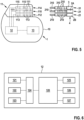
- the connector block 11 has connectors 110, 112, 114 to which electrode leads 2, 2A, 2B, 3 can be connected, as shown by way of example in Fig. 5 .
- Each connector 110, 112, 114 in this case forms a plug connector into which an assigned plug 21, 31 of an assigned electrode lead 2, 2A, 2B, 3 can be inserted in such a way that connection connectors 210, 310 of the plugs 21, 31 make electrical contact with assigned contact elements 111, 113, 115 of the connectors 110, 112, 114 and thus establish an electrical connection between the electrode leads 2, 2A, 2B, 3 and the defibrillation generator 1.
- the defibrillation generator 1 has a control device 12 which is functionally connected to the connectors 110, 112, 114, in particular the contact elements 111, 113, 115 of the connectors 110, 112, 114, so that signals can be received from the connectors 110, 112, 114 and signals can be fed to the connectors 110, 112, 114.
- the defibrillation generator 1 additionally has an energy store 13, especially in the form of a battery.
- the defibrillation generator 1 can be implanted in a patient and should remain in the patient for a long period of time, for example several years. All components of the defibrillation generator 1 are encapsulated by the housing 10 and are therefore enclosed in a moisture-proof manner.
- the control device 12 is configurable to assume different operating states. Depending on the number and combination of electrode leads 2, 2A, 2B, 3 connected to the defibrillation generator 1, the control device 12 can be operated in different operating states in order to provide a defibrillation function for the treatment of cardiac arrhythmias.
- the control device 12 has, for example, a first connector unit 121 associated with a first connector 110, a second connector unit 122 associated with a second connector 112, and a third connector unit 123 associated with a third connector 114.
- the connector units 121-123 are each connected to a switching unit 124, via which the connector units 121-123 can be controlled in a variably configurable manner.
- control device 12 can be configured to receive and deliver signals only via the connector unit 121, so that a defibrillation function is provided via the electrode lead 2 connected to the connector 110.
- a transvenously implanted electrode lead 3 is additionally connected to the connector 114, additional signals are also received via the connector unit 123 and, if necessary, are also delivered for intracardiac stimulation.
- the switching unit 124 can be realised by an electronic assembly. It is also conceivable that the switching unit 124 is implemented by means of control software and thus in software terms (without a hardware switch).
- the switching unit 124 is functionally connected to a control unit 120 of the control device 12, which evaluates received signals for the purpose of diagnostics and therapy management.
- the control unit 120 is connected to a ventricular stimulation unit 125, an atrial stimulation unit 126 and a cardioversion/defibrillation unit 127, via which signals for ventricular and/or atrial stimulation and for defibrillation can be generated and fed to connected electrode leads 2, 2A, 2B, 3.
- the control device 12 can be configured before implantation, during implantation or even after implantation.
- the configuration is carried out by programming, and the configuration adapts the control device 12 to a connected combination of electrode leads 2, 2A, 2B, 3 in order to be able to provide a defibrillation function via a connected combination of electrode leads 2, 2A, 2B, 3.
- control device 12 can also be designed to automatically detect which type and combination of electrode leads 2, 2A, 2B, 3 are connected to the defibrillation generator 1 in order to automatically carry out a configuration.
- Defibrillation energy (defibrillation shocks) is delivered via defibrillation electrode poles 202 of connected, non-transvenously implanted electrode leads 2, 2A, 2B.
- the connected electrode lead 2 has a single defibrillation electrode pole 202, which forms a dipole together with the housing 10 of the defibrillation generator 1.
- the housing 10 thus represents a counter-electrode for the defibrillation electrode pole 202 of the electrode lead 2, so that, between the defibrillation electrode pole 202 and the housing 10, stimulation energy can be injected into the heart H.
- the non-transvenously implanted electrode leads 2A, 2B connected to the defibrillation generator 1 each have one defibrillation electrode pole. Stimulation energy can be delivered between the two defibrillation electrode poles 202 of the electrode leads 2A, 2B.
- the housing 10 of the defibrillation generator 1 can also be included as a counter-electrode, for example by delivering stimulation energy between the defibrillation electrode pole 202 of one of the electrode leads 2A, 2B and the combination of the defibrillation electrode pole 202 of the other electrode lead 2B, 2A and the housing 10 of the defibrillation generator 1 (the defibrillation electrode pole 202 of the other electrode lead 2B, 2A and the housing 10 of the defibrillation generator 1 serve together as counter-electrode).
- Atrial and/or ventricular signals can be recorded via sensing electrode poles 200, 203.
- Sensing signals can be recorded here between each of the sensing electrode poles 200, 203 and the housing 10 of the defibrillation generator 1 as counter-electrode.
- signals can be recorded between the sensing electrodes 200, 203, which together form a dipole.
- An ECG can be derived from the sensing signals, on the basis of which diagnostics and therapy management can be carried out for a possible defibrillation.
- each electrode lead 2A, 2B has a sensing electrode pole 203.
- Sensing signals can be recorded accordingly between the sensing electrode poles 203 of the electrode leads 2A, 2B (which together form a dipole). Additionally or alternatively, sensing signals can be recorded between the sensing electrode pole 203 of each electrode lead 2A, 2B and the housing 10 of the defibrillation generator 1 as counter-electrode.
- an ECG can be derived from the sensing signals, which can be evaluated for diagnostics and therapy management.
- ATP Antitachycardic Pacing
- An electrode lead 3 can, for example, be added at a later time after an initial implantation of the defibrillation system, for example if slow ventricular tachycardias occur repeatedly in the patient or the sensing of signals for the purpose of diagnostics and therapy management is to be improved, because, for example, sensing via the non-transvenous electrode leads 2A, 2B is not sufficient.
- a transvenous coronary sinus electrode can be connected to the defibrillation generator 1, for example, which can have an additional fourth connector for this purpose.
- Left ventricular stimulation and/or sensing can be performed via such a coronary sinus electrode.
- Electrode leads 2, 2A, 2B, 3 can be marked by a suitable marking, for example a text, a colour marking or a radiopaque marking.
- Connectors 110, 112, 114 of the defibrillation generator 1 can also be marked.
- an electrode lead assembly 4 consisting of the electrode leads 2, 2A, 2B is implanted non-transvenously, the defibrillation system is easy to implant.
- the defibrillation generator 1 can be implanted subcutaneously or submuscularly, for example below the collarbone of a patient.
- Electrode leads 2, 2A, 2B can, for example, be implanted parasternally using a tunnelling technique and may thus extend outside the patient's heart H.
- Electrode leads may be constructed differently from the examples presented and may in particular have different combinations and arrangements of electrode poles.
- one or more electrode leads can be connected to a defibrillation generator, with at least some of the electrode leads being intended for non-transvenous implantation.
Landscapes
- Health & Medical Sciences (AREA)
- Cardiology (AREA)
- Radiology & Medical Imaging (AREA)
- Engineering & Computer Science (AREA)
- Biomedical Technology (AREA)
- Nuclear Medicine, Radiotherapy & Molecular Imaging (AREA)
- Life Sciences & Earth Sciences (AREA)
- Animal Behavior & Ethology (AREA)
- General Health & Medical Sciences (AREA)
- Public Health (AREA)
- Veterinary Medicine (AREA)
- Heart & Thoracic Surgery (AREA)
- Vascular Medicine (AREA)
- Electrotherapy Devices (AREA)
- Measurement And Recording Of Electrical Phenomena And Electrical Characteristics Of The Living Body (AREA)
Claims (15)
- Defibrillationsgenerator (1) für ein implantierbares Defibrillationssystem, umfassend:ein Gehäuse (10), einen Anschlussblock (11) zum Anschließen einer Elektrodenleitungsbaugruppe (4), die nicht-transvenös in einen Patienten zu implantieren ist, und eine Steuervorrichtung (12) zum Steuern des Betriebs des Defibrillationsgenerators (1), wobeider Anschlussblock (11) zwei Anschlüsse (110, 112) aufweist, an denen jeweils eine Elektrodenleitung (2, 2A, 2B) der Elektrodenleitungsbaugruppe (4) anschließbar ist, wobei die Elektrodenleitungen mindestens einen Defibrillationselektrodenpol (202) aufweisen,wobei die Steuervorrichtung (12) konfigurierbar ist für die Annahme eines ersten Betriebszustands, wenn nur an einem von den zwei Anschlüssen (110, 112) eine Elektrodenleitung (2, 2A, 2B) angeschlossen ist, oder eines zweiten Betriebszustands, wenn an jedem von den zwei Anschlüssen (110, 112) Elektrodenleitungen (2, 2A, 2B) angeschlossen sind, um in dem ersten Betriebszustand eine Defibrillationsfunktion über die an dem einen von den Anschlüssen (110, 112) angeschlossene Elektrodenleitung (2, 2A, 2B) bereitzustellen und in dem zweiten Betriebszustand eine Defibrillationsfunktion über die an den zwei Anschlüssen (110, 112) angeschlossenen Elektrodenleitungen (2, 2A, 2B) bereitzustellen,dadurch gekennzeichnet, dassdie Steuervorrichtung (12) einen ersten Empfangskanal zum Verarbeiten von über die Elektrodenleitungsbaugruppe (4) empfangenen ventrikulären Signalen und einen zweiten Empfangskanal zum Verarbeiten von über die Elektrodenleitungsbaugruppe (4) empfangenen atrialen Signalen aufweist, wobei der zweite Empfangskanal eine andere Verstärkung und/oder eine andere Filtereigenschaft aufweist als der erste Empfangskanal, um die atrialen Signale separat von den ventrikulären Signalen zu verarbeiten.
- Defibrillationsgenerator (1) nach Anspruch 1, dadurch gekennzeichnet, dass der Anschlussblock (11) einen dritten Anschluss (114) aufweist zum Anschließen einer Elektrodenleitung (3), die transvenös intrakardial zu implantieren ist.
- Defibrillationsgenerator (1) nach Anspruch 1 oder 2, dadurch gekennzeichnet, dass der Anschlussblock (11) einen vierten Anschluss aufweist zum Anschließen einer Koronarvenensinus-Elektrodenleitung, die transvenös zu implantieren ist.
- Defibrillationsgenerator (1) nach einem der Ansprüche 1 bis 3, dadurch gekennzeichnet, dass das Gehäuse (10) des Defibrillationsgenerators (1) zum Abgeben einer Stimulationsenergie eine Gegenelektrode zu mindestens einem Defibrillationselektrodenpol (202) einer Elektrodenleitung (2, 2A, 2b) der Elektrodenleitungsbaugruppe (4) bildet.
- Implantierbares Defibrillationssystem, einen Defibrillationsgenerator (1) nach einem der vorangehenden Ansprüche und eine Elektrodenleitungsbaugruppe (4) umfassend, die nicht-transvenös in einen Patienten zu implantieren ist.
- Implantierbares Defibrillationssystem nach Anspruch 5, dadurch gekennzeichnet, dass die Elektrodenleitungsbaugruppe (4) eine erste Elektrodenleitung (2A) zum Anschließen an einem ersten Anschluss (110) des Anschlussblocks (11) des Defibrillationsgenerators (1) und eine zweite Elektrodenleitung (2B) zum Anschließen an einem zweiten Anschluss (112) des Anschlussblocks (11) des Defibrillationsgenerators (1) umfasst, wobei die erste Elektrodenleitung (2A) und die zweite Elektrodenleitung (2B) jeweils mindestens einen Defibrillationselektrodenpol (202) aufweisen.
- Implantierbares Defibrillationssystem nach Anspruch 6, dadurch gekennzeichnet, dass die erste Elektrodenleitung (2A) und/oder die zweite Elektrodenleitung (2B) mindestens einen Abtastelektrodenpol (200, 201, 203) zum Detektieren ventrikulärer und/oder atrialer Signale aufweist/aufweisen.
- Implantierbares Defibrillationssystem nach Anspruch 7, dadurch gekennzeichnet, dass der mindestens eine Abtastelektrodenpol (200, 201, 203) als Ringelektrode gestaltet ist.
- Implantierbares Defibrillationssystem nach einem der Ansprüche 6 bis 8, dadurch gekennzeichnet, dass der mindestens eine Defibrillationselektrodenpol (202) als Helix gestaltet ist.
- Implantierbares Defibrillationssystem nach einem der Ansprüche 6 bis 9, dadurch gekennzeichnet, dass die erste Elektrodenleitung (2A) und/oder die zweite Elektrodenleitung (2B) mindestens einen atrialen Abtastelektrodenpol (200, 201) zum Detektieren atrialer Signale an einem distalen Ende der betreffenden Elektrodenleitung (2A, 2B), fern von dem Defibrillationsgenerator (1), aufweist/aufweisen.
- Implantierbares Defibrillationssystem nach einem der Ansprüche 6 bis 10, dadurch gekennzeichnet, dass die erste Elektrodenleitung (2A) und/oder die zweite Elektrodenleitung (2B) zwei atriale Messelektrodenpole (200, 201), die einen Dipol bilden, zum Detektieren atrialer Signale aufweist/aufweisen.
- Implantierbares Defibrillationssystem nach einem der Ansprüche 6 bis 11, dadurch gekennzeichnet, dass mindestens ein atrialer Messelektrodenpol (200, 201) zum Detektieren atrialer Signale und mindestens ein ventrikulärer Messelektrodenpol (203) zum Detektieren ventrikulärer Signale auf verschiedenen Seiten des mindestens einen Defibrillationselektrodenpols (202) der relevanten Elektrodenleitung (2A, 2B) angeordnet sind.
- Implantierbares Defibrillationssystem nach einem der Ansprüche 6 bis 12, gekennzeichnet durch eine dritte Elektrodenleitung (3) zum Anschließen an einer dritten Klemme (114) des Anschlussblocks (11) des Defibrillationsgenerators (1), wobei die dritte Elektrodenleitung (3) für eine intravenöse Implantation in das Herz (H) vorgesehen ist.
- Implantierbares Defibrillationssystem nach Anspruch 13, dadurch gekennzeichnet, dass die dritte Elektrodenleitung (3) ein Elektroden-Array (30) für eine intrakardiale Stimulation und/oder Abtastung aufweist.
- Verfahren zum Konfigurieren eines implantierbaren Defibrillationssystems, die folgenden Schritte umfassend:Bereitstellen eines Defibrillationsgenerators (1), der ein Gehäuse (10), einen Anschlussblocks (11) zum Anschließen einer Elektrodenleitungsbaugruppe (4) und eine Steuervorrichtung (12) zum Steuern des Betriebs des Defibrillationsgenerators (1) aufweist; undBereitstellen einer Elektrodenleitungsbaugruppe (4), die mindestens eine Elektrodenleitung (2, 2A, 2B, 3) umfasst, wobei die Elektrodenleitungsbaugruppe (4) für eine nicht-transvenöse Implantation in einen Patienten vorgesehen ist;entweder Anschließen einer Elektrodenleitung (2, 2A, 2B) der Elektrodenleitungsbaugruppe (4) an einem von zwei Anschlüssen (110, 112) des Anschlussblocks (11), wobei die Elektrodenleitung mindestens einen Defibrillationselektrodenpol (202) aufweist,oder Anschließen von zwei Elektrodenleitungen (2, 2A, 2B) der Elektrodenleitungsbaugruppe (4) an den zwei Anschlüssen (110, 112) des Anschlussblocks (11), wobei jede Elektrodenleitung mindestens einen Defibrillationselektrodenpol (202) aufweist; undKonfigurieren einer Schalteinheit (124) der Steuervorrichtung (12) für die Annahme eines ersten Betriebszustands, wenn an nur einem von den zwei Anschlüssen (110, 112) eine Elektrodenleitung (2, 2A, 2B) angeschlossen ist, oder eines zweiten Betriebszustands, wenn an jedem von den zwei Anschlüssen (110, 112) eine Elektrodenleitung (2, 2A, 2B) angeschlossen ist, wobei die Steuervorrichtung (12) in dem ersten Betriebszustand eine Defibrillationsfunktion über die an dem einen von den Anschlüssen (110, 112) angeschlossene Elektrodenleitung (2, 2A, 2B) bereitstellt und in dem zweiten Betriebszustand eine Defibrillationsfunktion über die an den zwei Anschlüssen (110, 112) angeschlossenen Elektrodenleitungen (2, 2A, 2B) bereitstellt, dadurch gekennzeichnet, dassdie Steuervorrichtung (12) einen ersten Empfangskanal zum Verarbeiten von über die Elektrodenleitungsbaugruppe (4) empfangenen ventrikulären Signalen und einen zweiten Empfangskanal zum Verarbeiten von über die Elektrodenleitungsbaugruppe (4) empfangenen atrialen Signalen aufweist, wobei der zweite Empfangskanal eine andere Verstärkung und/oder eine andere Filtereigenschaft aufweist als der erste Empfangskanal, um die atrialen Signale separat von den ventrikulären Signalen zu verarbeiten.
Applications Claiming Priority (2)
| Application Number | Priority Date | Filing Date | Title |
|---|---|---|---|
| EP19191170.0A EP3777968A1 (de) | 2019-08-12 | 2019-08-12 | Implantierbares defibrillationssystem |
| PCT/EP2020/072360 WO2021028377A1 (en) | 2019-08-12 | 2020-08-10 | Implantable defibrillation system |
Publications (2)
| Publication Number | Publication Date |
|---|---|
| EP4013491A1 EP4013491A1 (de) | 2022-06-22 |
| EP4013491B1 true EP4013491B1 (de) | 2024-10-02 |
Family
ID=67614439
Family Applications (2)
| Application Number | Title | Priority Date | Filing Date |
|---|---|---|---|
| EP19191170.0A Withdrawn EP3777968A1 (de) | 2019-08-12 | 2019-08-12 | Implantierbares defibrillationssystem |
| EP20750686.6A Active EP4013491B1 (de) | 2019-08-12 | 2020-08-10 | Implantierbares defibrillationssystem |
Family Applications Before (1)
| Application Number | Title | Priority Date | Filing Date |
|---|---|---|---|
| EP19191170.0A Withdrawn EP3777968A1 (de) | 2019-08-12 | 2019-08-12 | Implantierbares defibrillationssystem |
Country Status (5)
| Country | Link |
|---|---|
| US (1) | US12629531B2 (de) |
| EP (2) | EP3777968A1 (de) |
| JP (1) | JP2022543962A (de) |
| CN (1) | CN114096308A (de) |
| WO (1) | WO2021028377A1 (de) |
Families Citing this family (1)
| Publication number | Priority date | Publication date | Assignee | Title |
|---|---|---|---|---|
| EP4395876A1 (de) * | 2021-09-02 | 2024-07-10 | BIOTRONIK SE & Co. KG | Implantierbarer kardiovertierer-defibrillator |
Family Cites Families (26)
| Publication number | Priority date | Publication date | Assignee | Title |
|---|---|---|---|---|
| US5374279A (en) * | 1992-10-30 | 1994-12-20 | Medtronic, Inc. | Switchable connector block for implantable defibrillator |
| US5557210A (en) * | 1992-11-20 | 1996-09-17 | Pacesetter, Inc. | Universal cable connector for temporarily connecting implantable stimulation leads and implantable stimulation devices with a non-implantable system analyzer |
| US5545189A (en) * | 1995-11-02 | 1996-08-13 | Ventritex, Inc. | Case-activating switch assembly for an implantable cardiac stimulation device |
| US5778881A (en) * | 1996-12-04 | 1998-07-14 | Medtronic, Inc. | Method and apparatus for discriminating P and R waves |
| US5899930A (en) * | 1997-09-29 | 1999-05-04 | Cardiac Pacemakers, Inc. | Triple port and quadruple port in-line header designs |
| US6217525B1 (en) * | 1998-04-30 | 2001-04-17 | Medtronic Physio-Control Manufacturing Corp. | Reduced lead set device and method for detecting acute cardiac ischemic conditions |
| US7529592B2 (en) * | 2003-04-11 | 2009-05-05 | Cardiac Pacemakers, Inc. | Subcutaneous electrode and lead with temporary pharmacological agents |
| US20040215240A1 (en) * | 2003-04-11 | 2004-10-28 | Lovett Eric G. | Reconfigurable subcutaneous cardiac device |
| US7242987B2 (en) * | 2003-06-19 | 2007-07-10 | Medtronic, Inc. | Medical lead adaptor |
| US7218960B1 (en) * | 2003-06-24 | 2007-05-15 | Pacesetter, Inc. | System and method for detecting cardiac ischemia based on T-waves using an implantable medical device |
| US7398123B1 (en) * | 2004-03-05 | 2008-07-08 | Pacesetter, Inc. | Methods and devices for reducing the detection of inappropriate physiologic signals to reduce misdiagnosis of normal rhythms as tachyarrhythmias |
| US20070073346A1 (en) * | 2005-09-28 | 2007-03-29 | Giorgio Corbucci | Telemetry of combined endocavitary atrial and ventricular signals |
| WO2008088569A1 (en) * | 2007-01-18 | 2008-07-24 | Medtronic, Inc. | Bi-directional connector assembly for an implantable medical device |
| EP2155319B1 (de) * | 2007-04-20 | 2018-08-08 | Medtronic, Inc. | Implantierbare medizinische elektrische leitung und konnektor-anordnung |
| AU2009307979A1 (en) * | 2008-10-23 | 2010-04-29 | Cardiac Pacemakers, Inc. | Systems and methods to detect implantable medical device configuration changes affecting MRI conditional safety |
| US8200335B2 (en) * | 2008-10-31 | 2012-06-12 | Medtronic, Inc. | Implantable medical device lead connection assembly |
| US8731679B2 (en) * | 2010-04-29 | 2014-05-20 | Cardiac Pacemakers, Inc. | Implantable medical device configuration based on port usage |
| US8688200B2 (en) * | 2010-10-29 | 2014-04-01 | Medtronic, Inc. | Ischemia detection and classification |
| WO2013081747A1 (en) * | 2011-11-28 | 2013-06-06 | Cardiac Pacemakers, Inc. | Managing cross therapy sensing in a multiple therapy implantable device |
| WO2013101409A1 (en) * | 2011-12-27 | 2013-07-04 | Cardiac Pacemakers, Inc. | Managing cross therapy delivery in a multiple therapy implantable device |
| US9220913B2 (en) * | 2013-05-06 | 2015-12-29 | Medtronics, Inc. | Multi-mode implantable medical device |
| US20150306375A1 (en) * | 2014-04-25 | 2015-10-29 | Medtronic, Inc. | Implantable extravascular electrical stimulation lead having improved sensing and pacing capability |
| US9770599B2 (en) * | 2014-08-12 | 2017-09-26 | Cyberonics, Inc. | Vagus nerve stimulation and subcutaneous defibrillation system |
| US9636512B2 (en) * | 2014-11-05 | 2017-05-02 | Medtronic, Inc. | Implantable cardioverter-defibrillator (ICD) system having multiple common polarity extravascular defibrillation electrodes |
| WO2017015599A1 (en) * | 2015-07-23 | 2017-01-26 | Sri International | Robotic arm and robotic surgical system |
| WO2017196477A1 (en) * | 2016-05-12 | 2017-11-16 | University Of Florida Research Foundation, Inc. | Subcutaneous defibrillation |
-
2019
- 2019-08-12 EP EP19191170.0A patent/EP3777968A1/de not_active Withdrawn
-
2020
- 2020-08-10 WO PCT/EP2020/072360 patent/WO2021028377A1/en not_active Ceased
- 2020-08-10 JP JP2021573320A patent/JP2022543962A/ja active Pending
- 2020-08-10 US US17/631,744 patent/US12629531B2/en active Active
- 2020-08-10 CN CN202080049530.9A patent/CN114096308A/zh active Pending
- 2020-08-10 EP EP20750686.6A patent/EP4013491B1/de active Active
Also Published As
| Publication number | Publication date |
|---|---|
| EP3777968A1 (de) | 2021-02-17 |
| EP4013491A1 (de) | 2022-06-22 |
| WO2021028377A1 (en) | 2021-02-18 |
| US20220273959A1 (en) | 2022-09-01 |
| JP2022543962A (ja) | 2022-10-17 |
| US12629531B2 (en) | 2026-05-19 |
| CN114096308A (zh) | 2022-02-25 |
Similar Documents
| Publication | Publication Date | Title |
|---|---|---|
| US12083333B2 (en) | Implantable extravascular electrical stimulation lead having improved sensing and pacing capability | |
| JP7019082B2 (ja) | 波状構成を有する血管外植え込み型電気リード | |
| DE69933010T2 (de) | Vorrichtung zur überwachung und behandlung von arrythmien des herzens | |
| EP0661078B1 (de) | Leitung zur Herzdefibrillation mit atrialen Sensorelektroden und mindestens ventrikulärer Defibrillationselektrode | |
| US7383091B1 (en) | Medical electrical lead providing far-field signal attenuation | |
| US6327498B1 (en) | Implantable stimulation lead for use with an ICD device having automatic capture pacing features | |
| US20080086175A1 (en) | Method and apparatus for reducing defibrillation threshold | |
| US20040147994A1 (en) | Tachy lead system optimized for septal placement | |
| US8718767B2 (en) | Cardiac stimulating device | |
| US12629531B2 (en) | Implantable defibrillation system | |
| WO2021028411A1 (en) | Implantable defibrillation system | |
| EP3833426B1 (de) | Systeme zur anwendung von antitachykardie-stimulation mit subkutanen implantierbaren kardioverter-defibrillatoren | |
| US9327133B2 (en) | Implantable medical device |
Legal Events
| Date | Code | Title | Description |
|---|---|---|---|
| STAA | Information on the status of an ep patent application or granted ep patent |
Free format text: STATUS: UNKNOWN |
|
| STAA | Information on the status of an ep patent application or granted ep patent |
Free format text: STATUS: THE INTERNATIONAL PUBLICATION HAS BEEN MADE |
|
| PUAI | Public reference made under article 153(3) epc to a published international application that has entered the european phase |
Free format text: ORIGINAL CODE: 0009012 |
|
| STAA | Information on the status of an ep patent application or granted ep patent |
Free format text: STATUS: REQUEST FOR EXAMINATION WAS MADE |
|
| 17P | Request for examination filed |
Effective date: 20220114 |
|
| AK | Designated contracting states |
Kind code of ref document: A1 Designated state(s): AL AT BE BG CH CY CZ DE DK EE ES FI FR GB GR HR HU IE IS IT LI LT LU LV MC MK MT NL NO PL PT RO RS SE SI SK SM TR |
|
| DAV | Request for validation of the european patent (deleted) | ||
| DAX | Request for extension of the european patent (deleted) | ||
| STAA | Information on the status of an ep patent application or granted ep patent |
Free format text: STATUS: EXAMINATION IS IN PROGRESS |
|
| 17Q | First examination report despatched |
Effective date: 20230927 |
|
| GRAP | Despatch of communication of intention to grant a patent |
Free format text: ORIGINAL CODE: EPIDOSNIGR1 |
|
| STAA | Information on the status of an ep patent application or granted ep patent |
Free format text: STATUS: GRANT OF PATENT IS INTENDED |
|
| INTG | Intention to grant announced |
Effective date: 20240517 |
|
| GRAS | Grant fee paid |
Free format text: ORIGINAL CODE: EPIDOSNIGR3 |
|
| GRAA | (expected) grant |
Free format text: ORIGINAL CODE: 0009210 |
|
| STAA | Information on the status of an ep patent application or granted ep patent |
Free format text: STATUS: THE PATENT HAS BEEN GRANTED |
|
| AK | Designated contracting states |
Kind code of ref document: B1 Designated state(s): AL AT BE BG CH CY CZ DE DK EE ES FI FR GB GR HR HU IE IS IT LI LT LU LV MC MK MT NL NO PL PT RO RS SE SI SK SM TR |
|
| REG | Reference to a national code |
Ref country code: GB Ref legal event code: FG4D |
|
| REG | Reference to a national code |
Ref country code: CH Ref legal event code: EP |
|
| REG | Reference to a national code |
Ref country code: IE Ref legal event code: FG4D |
|
| REG | Reference to a national code |
Ref country code: DE Ref legal event code: R096 Ref document number: 602020038707 Country of ref document: DE |
|
| P01 | Opt-out of the competence of the unified patent court (upc) registered |
Free format text: CASE NUMBER: APP_62601/2024 Effective date: 20241125 |
|
| REG | Reference to a national code |
Ref country code: LT Ref legal event code: MG9D |
|
| REG | Reference to a national code |
Ref country code: NL Ref legal event code: MP Effective date: 20241002 |
|
| REG | Reference to a national code |
Ref country code: AT Ref legal event code: MK05 Ref document number: 1728028 Country of ref document: AT Kind code of ref document: T Effective date: 20241002 |
|
| PG25 | Lapsed in a contracting state [announced via postgrant information from national office to epo] |
Ref country code: NL Free format text: LAPSE BECAUSE OF FAILURE TO SUBMIT A TRANSLATION OF THE DESCRIPTION OR TO PAY THE FEE WITHIN THE PRESCRIBED TIME-LIMIT Effective date: 20241002 |
|
| PG25 | Lapsed in a contracting state [announced via postgrant information from national office to epo] |
Ref country code: NL Free format text: LAPSE BECAUSE OF FAILURE TO SUBMIT A TRANSLATION OF THE DESCRIPTION OR TO PAY THE FEE WITHIN THE PRESCRIBED TIME-LIMIT Effective date: 20241002 |
|
| PG25 | Lapsed in a contracting state [announced via postgrant information from national office to epo] |
Ref country code: HR Free format text: LAPSE BECAUSE OF FAILURE TO SUBMIT A TRANSLATION OF THE DESCRIPTION OR TO PAY THE FEE WITHIN THE PRESCRIBED TIME-LIMIT Effective date: 20241002 Ref country code: IS Free format text: LAPSE BECAUSE OF FAILURE TO SUBMIT A TRANSLATION OF THE DESCRIPTION OR TO PAY THE FEE WITHIN THE PRESCRIBED TIME-LIMIT Effective date: 20250202 Ref country code: PT Free format text: LAPSE BECAUSE OF FAILURE TO SUBMIT A TRANSLATION OF THE DESCRIPTION OR TO PAY THE FEE WITHIN THE PRESCRIBED TIME-LIMIT Effective date: 20250203 |
|
| PG25 | Lapsed in a contracting state [announced via postgrant information from national office to epo] |
Ref country code: FI Free format text: LAPSE BECAUSE OF FAILURE TO SUBMIT A TRANSLATION OF THE DESCRIPTION OR TO PAY THE FEE WITHIN THE PRESCRIBED TIME-LIMIT Effective date: 20241002 |
|
| PG25 | Lapsed in a contracting state [announced via postgrant information from national office to epo] |
Ref country code: BG Free format text: LAPSE BECAUSE OF FAILURE TO SUBMIT A TRANSLATION OF THE DESCRIPTION OR TO PAY THE FEE WITHIN THE PRESCRIBED TIME-LIMIT Effective date: 20241002 |
|
| PG25 | Lapsed in a contracting state [announced via postgrant information from national office to epo] |
Ref country code: ES Free format text: LAPSE BECAUSE OF FAILURE TO SUBMIT A TRANSLATION OF THE DESCRIPTION OR TO PAY THE FEE WITHIN THE PRESCRIBED TIME-LIMIT Effective date: 20241002 |
|
| PG25 | Lapsed in a contracting state [announced via postgrant information from national office to epo] |
Ref country code: NO Free format text: LAPSE BECAUSE OF FAILURE TO SUBMIT A TRANSLATION OF THE DESCRIPTION OR TO PAY THE FEE WITHIN THE PRESCRIBED TIME-LIMIT Effective date: 20250102 |
|
| PG25 | Lapsed in a contracting state [announced via postgrant information from national office to epo] |
Ref country code: GR Free format text: LAPSE BECAUSE OF FAILURE TO SUBMIT A TRANSLATION OF THE DESCRIPTION OR TO PAY THE FEE WITHIN THE PRESCRIBED TIME-LIMIT Effective date: 20250103 Ref country code: LV Free format text: LAPSE BECAUSE OF FAILURE TO SUBMIT A TRANSLATION OF THE DESCRIPTION OR TO PAY THE FEE WITHIN THE PRESCRIBED TIME-LIMIT Effective date: 20241002 Ref country code: AT Free format text: LAPSE BECAUSE OF FAILURE TO SUBMIT A TRANSLATION OF THE DESCRIPTION OR TO PAY THE FEE WITHIN THE PRESCRIBED TIME-LIMIT Effective date: 20241002 |
|
| PG25 | Lapsed in a contracting state [announced via postgrant information from national office to epo] |
Ref country code: CZ Free format text: LAPSE BECAUSE OF FAILURE TO SUBMIT A TRANSLATION OF THE DESCRIPTION OR TO PAY THE FEE WITHIN THE PRESCRIBED TIME-LIMIT Effective date: 20241002 Ref country code: PL Free format text: LAPSE BECAUSE OF FAILURE TO SUBMIT A TRANSLATION OF THE DESCRIPTION OR TO PAY THE FEE WITHIN THE PRESCRIBED TIME-LIMIT Effective date: 20241002 |
|
| PG25 | Lapsed in a contracting state [announced via postgrant information from national office to epo] |
Ref country code: RS Free format text: LAPSE BECAUSE OF FAILURE TO SUBMIT A TRANSLATION OF THE DESCRIPTION OR TO PAY THE FEE WITHIN THE PRESCRIBED TIME-LIMIT Effective date: 20250102 |
|
| PG25 | Lapsed in a contracting state [announced via postgrant information from national office to epo] |
Ref country code: SM Free format text: LAPSE BECAUSE OF FAILURE TO SUBMIT A TRANSLATION OF THE DESCRIPTION OR TO PAY THE FEE WITHIN THE PRESCRIBED TIME-LIMIT Effective date: 20241002 |
|
| REG | Reference to a national code |
Ref country code: DE Ref legal event code: R097 Ref document number: 602020038707 Country of ref document: DE |
|
| PG25 | Lapsed in a contracting state [announced via postgrant information from national office to epo] |
Ref country code: DK Free format text: LAPSE BECAUSE OF FAILURE TO SUBMIT A TRANSLATION OF THE DESCRIPTION OR TO PAY THE FEE WITHIN THE PRESCRIBED TIME-LIMIT Effective date: 20241002 |
|
| PG25 | Lapsed in a contracting state [announced via postgrant information from national office to epo] |
Ref country code: EE Free format text: LAPSE BECAUSE OF FAILURE TO SUBMIT A TRANSLATION OF THE DESCRIPTION OR TO PAY THE FEE WITHIN THE PRESCRIBED TIME-LIMIT Effective date: 20241002 |
|
| PG25 | Lapsed in a contracting state [announced via postgrant information from national office to epo] |
Ref country code: RO Free format text: LAPSE BECAUSE OF FAILURE TO SUBMIT A TRANSLATION OF THE DESCRIPTION OR TO PAY THE FEE WITHIN THE PRESCRIBED TIME-LIMIT Effective date: 20241002 |
|
| PG25 | Lapsed in a contracting state [announced via postgrant information from national office to epo] |
Ref country code: SK Free format text: LAPSE BECAUSE OF FAILURE TO SUBMIT A TRANSLATION OF THE DESCRIPTION OR TO PAY THE FEE WITHIN THE PRESCRIBED TIME-LIMIT Effective date: 20241002 |
|
| PG25 | Lapsed in a contracting state [announced via postgrant information from national office to epo] |
Ref country code: IT Free format text: LAPSE BECAUSE OF FAILURE TO SUBMIT A TRANSLATION OF THE DESCRIPTION OR TO PAY THE FEE WITHIN THE PRESCRIBED TIME-LIMIT Effective date: 20241002 |
|
| PLBE | No opposition filed within time limit |
Free format text: ORIGINAL CODE: 0009261 |
|
| STAA | Information on the status of an ep patent application or granted ep patent |
Free format text: STATUS: NO OPPOSITION FILED WITHIN TIME LIMIT |
|
| PG25 | Lapsed in a contracting state [announced via postgrant information from national office to epo] |
Ref country code: SE Free format text: LAPSE BECAUSE OF FAILURE TO SUBMIT A TRANSLATION OF THE DESCRIPTION OR TO PAY THE FEE WITHIN THE PRESCRIBED TIME-LIMIT Effective date: 20241002 |
|
| 26N | No opposition filed |
Effective date: 20250703 |
|
| PGFP | Annual fee paid to national office [announced via postgrant information from national office to epo] |
Ref country code: DE Payment date: 20250819 Year of fee payment: 6 |
|
| PGFP | Annual fee paid to national office [announced via postgrant information from national office to epo] |
Ref country code: CH Payment date: 20250901 Year of fee payment: 6 |
|
| PGFP | Annual fee paid to national office [announced via postgrant information from national office to epo] |
Ref country code: IE Payment date: 20250821 Year of fee payment: 6 |
|
| PG25 | Lapsed in a contracting state [announced via postgrant information from national office to epo] |
Ref country code: MC Free format text: LAPSE BECAUSE OF FAILURE TO SUBMIT A TRANSLATION OF THE DESCRIPTION OR TO PAY THE FEE WITHIN THE PRESCRIBED TIME-LIMIT Effective date: 20241002 |
|
| PG25 | Lapsed in a contracting state [announced via postgrant information from national office to epo] |
Ref country code: LU Free format text: LAPSE BECAUSE OF NON-PAYMENT OF DUE FEES Effective date: 20250810 |
|
| GBPC | Gb: european patent ceased through non-payment of renewal fee |
Effective date: 20250810 |
|
| REG | Reference to a national code |
Ref country code: BE Ref legal event code: MM Effective date: 20250831 |
|
| PG25 | Lapsed in a contracting state [announced via postgrant information from national office to epo] |
Ref country code: LT Free format text: LAPSE BECAUSE OF FAILURE TO SUBMIT A TRANSLATION OF THE DESCRIPTION OR TO PAY THE FEE WITHIN THE PRESCRIBED TIME-LIMIT Effective date: 20241002 |
|
| PG25 | Lapsed in a contracting state [announced via postgrant information from national office to epo] |
Ref country code: GB Free format text: LAPSE BECAUSE OF NON-PAYMENT OF DUE FEES Effective date: 20250810 |
|
| PG25 | Lapsed in a contracting state [announced via postgrant information from national office to epo] |
Ref country code: BE Free format text: LAPSE BECAUSE OF NON-PAYMENT OF DUE FEES Effective date: 20250831 |
|
| PG25 | Lapsed in a contracting state [announced via postgrant information from national office to epo] |
Ref country code: FR Free format text: LAPSE BECAUSE OF NON-PAYMENT OF DUE FEES Effective date: 20250831 |