EP4013309B1 - Steuerbares mehrebenen-ultraschallbildgebungssystem - Google Patents
Steuerbares mehrebenen-ultraschallbildgebungssystem Download PDFInfo
- Publication number
- EP4013309B1 EP4013309B1 EP20751173.4A EP20751173A EP4013309B1 EP 4013309 B1 EP4013309 B1 EP 4013309B1 EP 20751173 A EP20751173 A EP 20751173A EP 4013309 B1 EP4013309 B1 EP 4013309B1
- Authority
- EP
- European Patent Office
- Prior art keywords
- ultrasound
- image plane
- image
- buip
- beamforming
- Prior art date
- Legal status (The legal status is an assumption and is not a legal conclusion. Google has not performed a legal analysis and makes no representation as to the accuracy of the status listed.)
- Active
Links
Images


Classifications
-
- G—PHYSICS
- G01—MEASURING; TESTING
- G01S—RADIO DIRECTION-FINDING; RADIO NAVIGATION; DETERMINING DISTANCE OR VELOCITY BY USE OF RADIO WAVES; LOCATING OR PRESENCE-DETECTING BY USE OF THE REFLECTION OR RERADIATION OF RADIO WAVES; ANALOGOUS ARRANGEMENTS USING OTHER WAVES
- G01S15/00—Systems using the reflection or reradiation of acoustic waves, e.g. sonar systems
- G01S15/88—Sonar systems specially adapted for specific applications
- G01S15/89—Sonar systems specially adapted for specific applications for mapping or imaging
- G01S15/8906—Short-range imaging systems; Acoustic microscope systems using pulse-echo techniques
- G01S15/8909—Short-range imaging systems; Acoustic microscope systems using pulse-echo techniques using a static transducer configuration
- G01S15/8915—Short-range imaging systems; Acoustic microscope systems using pulse-echo techniques using a static transducer configuration using a transducer array
- G01S15/8925—Short-range imaging systems; Acoustic microscope systems using pulse-echo techniques using a static transducer configuration using a transducer array the array being a two-dimensional transducer configuration, i.e. matrix or orthogonal linear arrays
-
- A—HUMAN NECESSITIES
- A61—MEDICAL OR VETERINARY SCIENCE; HYGIENE
- A61B—DIAGNOSIS; SURGERY; IDENTIFICATION
- A61B8/00—Diagnosis using ultrasonic, sonic or infrasonic waves
- A61B8/13—Tomography
- A61B8/14—Echo-tomography
- A61B8/145—Echo-tomography characterised by scanning multiple planes
-
- A—HUMAN NECESSITIES
- A61—MEDICAL OR VETERINARY SCIENCE; HYGIENE
- A61B—DIAGNOSIS; SURGERY; IDENTIFICATION
- A61B8/00—Diagnosis using ultrasonic, sonic or infrasonic waves
- A61B8/12—Diagnosis using ultrasonic, sonic or infrasonic waves in body cavities or body tracts, e.g. by using catheters
-
- A—HUMAN NECESSITIES
- A61—MEDICAL OR VETERINARY SCIENCE; HYGIENE
- A61B—DIAGNOSIS; SURGERY; IDENTIFICATION
- A61B8/00—Diagnosis using ultrasonic, sonic or infrasonic waves
- A61B8/42—Details of probe positioning or probe attachment to the patient
- A61B8/4245—Details of probe positioning or probe attachment to the patient involving determining the position of the probe, e.g. with respect to an external reference frame or to the patient
- A61B8/4263—Details of probe positioning or probe attachment to the patient involving determining the position of the probe, e.g. with respect to an external reference frame or to the patient using sensors not mounted on the probe, e.g. mounted on an external reference frame
-
- A—HUMAN NECESSITIES
- A61—MEDICAL OR VETERINARY SCIENCE; HYGIENE
- A61B—DIAGNOSIS; SURGERY; IDENTIFICATION
- A61B8/00—Diagnosis using ultrasonic, sonic or infrasonic waves
- A61B8/44—Constructional features of the ultrasonic, sonic or infrasonic diagnostic device
- A61B8/4483—Constructional features of the ultrasonic, sonic or infrasonic diagnostic device characterised by features of the ultrasound transducer
- A61B8/4488—Constructional features of the ultrasonic, sonic or infrasonic diagnostic device characterised by features of the ultrasound transducer the transducer being a phased array
-
- A—HUMAN NECESSITIES
- A61—MEDICAL OR VETERINARY SCIENCE; HYGIENE
- A61B—DIAGNOSIS; SURGERY; IDENTIFICATION
- A61B8/00—Diagnosis using ultrasonic, sonic or infrasonic waves
- A61B8/46—Ultrasonic, sonic or infrasonic diagnostic devices with special arrangements for interfacing with the operator or the patient
- A61B8/461—Displaying means of special interest
- A61B8/466—Displaying means of special interest adapted to display 3D data
-
- A—HUMAN NECESSITIES
- A61—MEDICAL OR VETERINARY SCIENCE; HYGIENE
- A61B—DIAGNOSIS; SURGERY; IDENTIFICATION
- A61B8/00—Diagnosis using ultrasonic, sonic or infrasonic waves
- A61B8/48—Diagnostic techniques
- A61B8/483—Diagnostic techniques involving the acquisition of a 3D volume of data
-
- A—HUMAN NECESSITIES
- A61—MEDICAL OR VETERINARY SCIENCE; HYGIENE
- A61B—DIAGNOSIS; SURGERY; IDENTIFICATION
- A61B8/00—Diagnosis using ultrasonic, sonic or infrasonic waves
- A61B8/52—Devices using data or image processing specially adapted for diagnosis using ultrasonic, sonic or infrasonic waves
- A61B8/5215—Devices using data or image processing specially adapted for diagnosis using ultrasonic, sonic or infrasonic waves involving processing of medical diagnostic data
-
- G—PHYSICS
- G01—MEASURING; TESTING
- G01S—RADIO DIRECTION-FINDING; RADIO NAVIGATION; DETERMINING DISTANCE OR VELOCITY BY USE OF RADIO WAVES; LOCATING OR PRESENCE-DETECTING BY USE OF THE REFLECTION OR RERADIATION OF RADIO WAVES; ANALOGOUS ARRANGEMENTS USING OTHER WAVES
- G01S15/00—Systems using the reflection or reradiation of acoustic waves, e.g. sonar systems
- G01S15/88—Sonar systems specially adapted for specific applications
- G01S15/89—Sonar systems specially adapted for specific applications for mapping or imaging
- G01S15/8906—Short-range imaging systems; Acoustic microscope systems using pulse-echo techniques
- G01S15/899—Combination of imaging systems with ancillary equipment
-
- G—PHYSICS
- G01—MEASURING; TESTING
- G01S—RADIO DIRECTION-FINDING; RADIO NAVIGATION; DETERMINING DISTANCE OR VELOCITY BY USE OF RADIO WAVES; LOCATING OR PRESENCE-DETECTING BY USE OF THE REFLECTION OR RERADIATION OF RADIO WAVES; ANALOGOUS ARRANGEMENTS USING OTHER WAVES
- G01S7/00—Details of systems according to groups G01S13/00, G01S15/00, G01S17/00
- G01S7/52—Details of systems according to groups G01S13/00, G01S15/00, G01S17/00 of systems according to group G01S15/00
- G01S7/52017—Details of systems according to groups G01S13/00, G01S15/00, G01S17/00 of systems according to group G01S15/00 particularly adapted to short-range imaging
- G01S7/52053—Display arrangements
- G01S7/52057—Cathode ray tube displays
- G01S7/52074—Composite displays, e.g. split-screen displays; Combination of multiple images or of images and alphanumeric tabular information
-
- G—PHYSICS
- G01—MEASURING; TESTING
- G01S—RADIO DIRECTION-FINDING; RADIO NAVIGATION; DETERMINING DISTANCE OR VELOCITY BY USE OF RADIO WAVES; LOCATING OR PRESENCE-DETECTING BY USE OF THE REFLECTION OR RERADIATION OF RADIO WAVES; ANALOGOUS ARRANGEMENTS USING OTHER WAVES
- G01S7/00—Details of systems according to groups G01S13/00, G01S15/00, G01S17/00
- G01S7/52—Details of systems according to groups G01S13/00, G01S15/00, G01S17/00 of systems according to group G01S15/00
- G01S7/52017—Details of systems according to groups G01S13/00, G01S15/00, G01S17/00 of systems according to group G01S15/00 particularly adapted to short-range imaging
- G01S7/52085—Details related to the ultrasound signal acquisition, e.g. scan sequences
-
- A—HUMAN NECESSITIES
- A61—MEDICAL OR VETERINARY SCIENCE; HYGIENE
- A61B—DIAGNOSIS; SURGERY; IDENTIFICATION
- A61B8/00—Diagnosis using ultrasonic, sonic or infrasonic waves
- A61B8/52—Devices using data or image processing specially adapted for diagnosis using ultrasonic, sonic or infrasonic waves
- A61B8/5215—Devices using data or image processing specially adapted for diagnosis using ultrasonic, sonic or infrasonic waves involving processing of medical diagnostic data
- A61B8/5238—Devices using data or image processing specially adapted for diagnosis using ultrasonic, sonic or infrasonic waves involving processing of medical diagnostic data for combining image data of patient, e.g. merging several images from different acquisition modes into one image
- A61B8/5246—Devices using data or image processing specially adapted for diagnosis using ultrasonic, sonic or infrasonic waves involving processing of medical diagnostic data for combining image data of patient, e.g. merging several images from different acquisition modes into one image combining images from the same or different imaging techniques, e.g. color Doppler and B-mode
- A61B8/5253—Devices using data or image processing specially adapted for diagnosis using ultrasonic, sonic or infrasonic waves involving processing of medical diagnostic data for combining image data of patient, e.g. merging several images from different acquisition modes into one image combining images from the same or different imaging techniques, e.g. color Doppler and B-mode combining overlapping images, e.g. spatial compounding
Definitions
- a multi-plane ultrasound imaging system provides a medical practitioner with anatomical views to support a medical procedure.
- the additional views provided by a multi-plane imaging system provide improved visualization of the anatomy whilst avoiding the typically lower resolution or lower frame rates associated with full three-dimensional imaging.
- a steerable multi-plane ultrasound imaging system for steering a plurality of intersecting image planes of a beamforming ultrasound imaging probe based on ultrasound signals transmitted between the beamforming ultrasound imaging probe and an ultrasound transducer disposed within a field of view of the probe includes a beamforming ultrasound imaging probe and an ultrasound tracking system.
- the beamforming ultrasound imaging probe generates ultrasound beams that define a plurality of intersecting image planes, including a first image plane and a second image plane.
- a steerable multi-plane ultrasound imaging system is described with particular reference to a beamforming ultrasound imaging probe in the form of a TTE probe. It is however to be appreciated that use of the system with alternative ultrasound imaging probes is also contemplated, including but not limited to IVUS, TEE, TNE, ICE, or TRUS, ultrasound imaging probes. Moreover, use of the system in combination with an interventional device is described with particular reference to the interventional device being a medical needle.
- a catheter a guidewire, a probe, an endoscope, an electrode, a robot, a filter device, a balloon device, a stent, a mitral clip, a left atrial appendage closure device, an aortic valve, a pacemaker, an intravenous line, a drainage line, a surgical tool, a tissue sealing device, a tissue cutting device or an implantable device.
- interventional devices including but not limited to a catheter, a guidewire, a probe, an endoscope, an electrode, a robot, a filter device, a balloon device, a stent, a mitral clip, a left atrial appendage closure device, an aortic valve, a pacemaker, an intravenous line, a drainage line, a surgical tool, a tissue sealing device, a tissue cutting device or an implantable device.
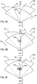
- Steerable multi-plane ultrasound imaging system MPUIS in Fig. 1 is configured to generate and to steer multiple intersecting image planes, as exemplified by image planes PL 1 , PL 2 of beamforming ultrasound imaging probe BUIP. As illustrated in Fig. 1 , image planes PL 1 , PL 2 intersect transversely. In some implementations the planes intersect orthogonally.
- the image planes are each defined by a plurality of beams within which ultrasound signals, specifically ultrasound imaging signals, are transmitted and received. Image planes PL 1 , PL 2 may be steered, i.e. their orientations may be adjusted, using beamsteering techniques known from the ultrasound field.
- Ultrasound tracking system UTS in Fig. 1 includes electronic circuitry and/ or a processor in combination with a memory, which processor executes instructions stored in the memory and which instructions correspond to the method steps of:
- image reconstruction unit IRU may generate a reconstructed ultrasound image corresponding to each of image planes PL 1 , PL 2 and display DISP may display an image corresponding to each of image planes PL 1 , PL 2 .
- the reconstructed image may be displayed as a live image, and in other implementations the display of the reconstructed image may be synchronized to a particular cardiac or respiratory cycle and image data displayed only for a predetermined phase of the cycle.
- cardiac “gating” may for example be used to "freeze” the mitral valve in successive open or closed states, thereby allowing a medical practitioner to focus on this particular portion of the anatomy.
- image-based segmentation, or cardiac/ respiratory sensor data received from a sensor such as an electrocardiogram sensor, i.e. ECG sensor, an ultrasound sensor, a strain sensor, a camera, or motion sensor and so forth are contemplated for determining the relevant cycle.
- first image plane PL 1 and second image plane PL 2 are adjusted by:
- the ultrasound tracking system UTS in Fig. 1 may identify a maximum signal ultrasound beam B max for the first image plane PL 1 .
- the maximum signal ultrasound beam B max is defined as the ultrasound beam for which the magnitude of ultrasound signals transmitted between the beamforming ultrasound imaging probe BUIP and the ultrasound transducer S is the highest for first image plane PL 1 .
- causing beamforming ultrasound imaging probe BUIP to adjust the second image plane PL 2 such that the intersection AZ between the first image plane and the second image plane passes through the position of the ultrasound transducer S may include causing the second image plane PL 2 to intersect the maximum signal ultrasound beam B max .
- the maximum signal ultrasound beam B max can be readily identified. This beam thus provides an easy reference beam to which the second image plane PL 2 may be aligned.
- FIG. 3 illustrates the adjusting of image planes PL 1 , PL 2 of a beamforming ultrasound imaging probe BUIP based on an image feature detected in image plane PL 1 .
- the image feature is a medical needle NL which is segmented in image plane PL 1 .
- the orientation of image plane PL 1 is adjusted, in the present example by rotating image plane PL 1 in order to maximize the segmented area of medical needle NL by rotating image plane PL 1 such that it is parallel to and passes through the longitudinal axis of medical needle NL.
- image plane PL 1 may be rotated such that it passes perpendicularly through the longitudinal axis of medical needle NL.
- the image plane(s) may thus be adjusted by maximizing the correspondence between an expected image shape and a shape segmented in the image plane.
- the image plane may be rotated until the segmented shape becomes as close as possible to a circle or a straight line; a circle and a straight line being orthogonal cross sectional shapes of the medical needle.
- Other angles of intersection between the longitudinal axis of medical needle NL and image plane PL 1 may likewise be provided in a similar manner by rotating image plane PL 1 until a target cross sectional shape is provided by the segmentation, thereafter making adjustments to image plane PL 1 to maintain the target cross sectional shape.
- Image plane PL 2 and indeed any other image planes not shown in Fig. 3 , may likewise be rotated in order to either maintain a constant mutual angular relationship with image plane PL 1 with respect to intersection AZ, or their image planes may remain unadjusted.
- parallel and perpendicular refer to within ⁇ 5 degrees of exactly parallel and exactly perpendicular.
- image planes PL 1 , PL 2 , and any additional image planes that may exist may be adjusted simultaneously in response to movements of the image feature whilst maintaining a constant angle of intersection. This advantageously allows for e.g. the tracking of an anatomical feature whilst maintaining the intersection of the image planes at a reference point, specifically the position of ultrasound transducer S.
- the selection of the image feature may in some instances be determined based on user input, for example based on user input received from a user interface comprising a menu of image features or based on input in the form of a user selection of a portion of the reconstructed image corresponding to image plane PL 1 .
- the at least one of the first image plane PL 1 and the second image plane PL 2 may be adjusted based on the image feature by:
- the image quality metric may for instance be i) a completeness of a segmentation of the image feature in the respective image plane PL 1 , PL 2 or ii) a closeness of a fit of the segmentation to a model to the image feature.
- the image quality metric may represent the completeness, i.e. the intensity and/ or the contiguity of the pixels of a segmented annular image feature corresponding to the aortic valve.
- the annular feature here serves as a model of the desired anatomical region.
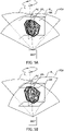
- image reconstruction unit IRU may reconstruct a three-dimensional ultrasound image by rotating one or more of the image planes PL 1..n whilst maintaining the intersection of the image planes with the position of the ultrasound transducer.
- Fig. 4 illustrates the reconstruction of a three-dimensional ultrasound image using ultrasound image data obtained whilst rotating image planes PL 1 and PL 2 .
- beamforming ultrasound imaging probe BUIP which may be used in place of the same-referenced item in Fig.
- image data is illustrated as generating image data for each of image planes PL 1 , PL 2 by means of the thick solid lines for each image plane. Whilst maintaining that intersection AZ passes through the position of sensor S, both image planes are rotated through 90 degrees about intersection AZ and image data at each of a plurality of rotational angles is generated and recorded. The image data is then rendered into a three-dimensional image.
- data from only one plane, such as image plane PL 1 may be provided and used in such a three-dimensional image reconstruction. For example, data may be recorded and rendered for image plane PL 1 whilst rotating the plane through 180 degrees, or through another angle. The use of other numbers of image planes and other rotational angles than these examples is also contemplated in this respect.
- some overlap in the image data generated at the start and the end of the rotation may be desirable in order to provide redundant overlapping image data in order to match the image data obtained at the start and the ends of the rotation.
- angles slightly larger than 360°/2 n may be used in some implementations, wherein n is the number of image planes.
- steerable multi-plane ultrasound imaging system MPUIS in Fig. 1 also includes image reconstruction unit IRU that reconstruct ultrasound images based on ultrasound image data generated by the beamforming ultrasound imaging probe BUIP for each of a plurality of image planes such as image planes PL 1 , PL 2 .
- Ultrasound tracking system UTS may also cause beamforming ultrasound imaging probe BUIP to adjust one or more of image planes PL 1 , PL 2 by rotating the image plane(s) about the intersection AZ between the first image plane PL 1 and the second image plane PL 2 , and to reconstruct a three-dimensional ultrasound image based on ultrasound image data corresponding to at least one of the plurality of intersecting image planes during the rotation.
- steerable multi-plane ultrasound imaging system MPUIS in Fig. 1 may include an image reconstruction unit IRU and an image registration unit IREGU that generates an overlay image wherein reconstructed ultrasound images are registered to an anatomical model.
- beamforming ultrasound imaging probe BUIP which may be used in place of the same-referenced item in Fig.
- Fig. 5 also includes an anatomical model AM, by means of the segmented structure within the cubic reference frame, which model corresponds to an anatomical region within field of view FOV.
- Anatomical model AM may be stored in a memory comprising a library of anatomical models that are selectable based on user input.
- Ultrasound images from one or more of image planes PL 1 , PL 2 are registered to anatomical model AM.
- Image registration unit IREGU generates an overlay image in which the reconstructed ultrasound image(s) are registered to the anatomical model.
- the ultrasound tracking system UTS then causes beamforming ultrasound imaging probe BUIP to adjust image plane PL 1 in order to achieve a desired view defined in the anatomical model.
- anatomical model AM i.e. the segmented structure within the cubic reference frame, includes a visualization plane VPL as indicated by the plane with dashed lines.
- Visualization plane VPL may for example correspond to a desired image slice through the anatomy. An example of such a slice could be the annular plane used to visualize the mitral valve and the annulus during a mitral clip procedure.
- Visualization plane VPL may be selected by means of user input received via user input device - for example a user selecting a plane, i.e. a desired view on an image of the anatomical model.
- Ultrasound tracking system UTS causes beamforming ultrasound imaging probe BUIP to provide the desired view VPL by rotating one or more of image planes PL 1 , PL 2 about the intersection AZ of the first image plane PL 1 and the second image plane PL 2 such that, one of the planes, in this example, image plane PL 2 is parallel to visualization plane VPL. Whilst in Fig. 5 , only image plane PL 2 is rotated, and image plane PL 1 remains un-adjusted, both image planes PL 1 and PL 2 may alternatively be caused to rotate such that one of the planes is parallel to visualization plane VPL.
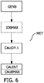
- Fig. 6 illustrates a flowchart of a method MET that may be used in conjunction with some aspects of the disclosure.
- Method MET may be used to steer a plurality of intersecting image planes PL 1..n of a beamforming ultrasound imaging probe BUIP based on ultrasound signals transmitted between the beamforming ultrasound imaging probe BUIP and an ultrasound transducer S disposed within a field of view FOV of the probe BUIP.
- Method MET may in particular be used in any of the systems described with reference to Fig. 1 - Fig. 5 .
- Method MET includes the steps of:
- the medium can be an electronic, magnetic, optical, electromagnetic, infrared, or semiconductor system, or apparatus or device, or a propagation medium.
- Examples of a computer-readable medium include a semiconductor or solid state memory, magnetic tape, a removable computer diskette, a random access memory "RAM”, a read-only memory "ROM”, a rigid magnetic disk and an optical disk.
- Current examples of optical disks include compact disk - read only memory "CD-ROM”, compact disk - read/write "CD-R/W”, Blu-Ray TM and DVD.
Landscapes
- Health & Medical Sciences (AREA)
- Life Sciences & Earth Sciences (AREA)
- Engineering & Computer Science (AREA)
- Physics & Mathematics (AREA)
- Molecular Biology (AREA)
- General Health & Medical Sciences (AREA)
- Nuclear Medicine, Radiotherapy & Molecular Imaging (AREA)
- Pathology (AREA)
- Radiology & Medical Imaging (AREA)
- Biomedical Technology (AREA)
- Heart & Thoracic Surgery (AREA)
- Medical Informatics (AREA)
- Veterinary Medicine (AREA)
- Surgery (AREA)
- Animal Behavior & Ethology (AREA)
- Biophysics (AREA)
- Public Health (AREA)
- Radar, Positioning & Navigation (AREA)
- Remote Sensing (AREA)
- Acoustics & Sound (AREA)
- Computer Networks & Wireless Communication (AREA)
- General Physics & Mathematics (AREA)
- Computer Vision & Pattern Recognition (AREA)
- Gynecology & Obstetrics (AREA)
- Computer Graphics (AREA)
- General Engineering & Computer Science (AREA)
- Ultra Sonic Daignosis Equipment (AREA)
Claims (16)
- Steuerbares Mehrebenen-Ultraschallabbildungssystem (MPUIS) zum Steuern einer Vielzahl von sich schneidenden Bildebenen (PL1..n) einer strahlformenden Ultraschallabbildungssonde (BUIP) auf der Grundlage von Ultraschallsignalen, die zwischen der strahlformenden Ultraschallabbildungssonde (BUIP) und einem Ultraschallwandler (S) übertragen werden, der in einem Sichtfeld (FOV) der Sonde (BUIP) angeordnet ist, wobei das System Folgendes umfasst:eine Ultraschall-Bildgebungssondemit Strahlformung (BUIP); undein Ultraschall-Ortungs-System (UTS);wobei die strahlformende Ultraschallabbildungssonde (BUIP) konfiguriert ist, umUltraschallstrahlen zu erzeugen, die eine Vielzahl von sich schneidenden Bildebenen (PL1..n) definieren, wobei dieBildebenen mindestens eine erste Bildebene (PL1) und eine zweite Bildebene (PL2) umfassen;wobei das Ultraschallverfolgungssystem (UTS) mit der strahlformenden Ultraschallabbildungssonde (BUIP) in Verbindung steht und so konfiguriert ist, dass es die strahlformende Ultraschallabbildungssonde (BUIP) veranlasst, eine Ausrichtung der ersten Bildebene (PL1) so einzustellen, dass die erste Bildebene durch eine Position (POS) des Ultraschallwandlers (S) verläuft, indem eine Größe von Ultraschallsignalen maximiert wird, die zwischen der strahlformenden Ultraschallabbildungssonde (BUIP) und dem Ultraschallwandler (S) übertragen werden; und um die strahlformende Ultraschall-Bildgebungssonde (BUIP) zu veranlassen, eine Ausrichtung der zweiten Bildebene (PL2) so einzustellen, dass ein Schnittpunkt (AZ) zwischen der ersten Bildebene und der zweiten Bildebene durch die Position desUltraschallwandlers (S) verläuft.
- System nach Anspruch 1, wobei i) der Ultraschallwandler (S) ein Ultraschallsensor ist, und wobei die Ultraschallsignale Ultraschallabbildungssignale sind, die von der strahlformenden Ultraschallabbildungssonde (BUIP) gesendet und von dem Ultraschallsensor (S) empfangen werden; oder ii) der Ultraschallwandler (S) ein Ultraschallsensor ist, und wobei die Ultraschallsignale Ultraschallverfolgungssignale sind, die von der strahlformenden Ultraschallabbildungssonde (BUIP) übertragen werden, wobei die Ultraschallverfolgungssignale zwischen Ultraschallabbildungssignalen verschachtelt sind und die Ultraschallverfolgungssignale von dem Ultraschallsensor (S) empfangen werden; oder wobei iii) der Ultraschallwandler (S) ein Ultraschallsensor ist, und wobei die Ultraschallsignale
Ultraschallsensor ist, und wobei die Ultraschallsignale Ultraschallverfolgungssignale sind, die von jedem einer Vielzahl von Ultraschallsendern gesendet werden, die auf der strahlformenden Ultraschallabbildungssonde (BUIP) angeordnet sind, wobei die Ultraschallverfolgungssignale von dem Ultraschallsensor (S) empfangen werden; oder wobei iv) der Ultraschallwandler (S) ein Ultraschallsender ist, und wobei die Ultraschallsignale von dem Ultraschallsender gesendet und von der strahlformenden Ultraschallabbildungssonde (BUIP) empfangen werden; oder wobei iv) der Ultraschallwandler (S) ein Ultraschallsender ist, und wobei die Ultraschallsignale von dem Ultraschallsender gesendet und von jedem einer Vielzahl von Ultraschallempfängern empfangen werden, die an der strahlformenden Ultraschallabbildungssonde (BUIP) angeordnet sind. - System nach Anspruch 1, wobei das Ultraschallverfolgungssystem (UTS) ferner so konfiguriert ist, dass es einen Ultraschallstrahl mit maximalem Signal (Bmax) für die erste Bildebene (PL1) identifiziert, wobei der Ultraschallstrahl mit maximalem Signal (Bmax) ein Ultraschallstrahl ist, für den die Größe der Ultraschallsignale, die zwischen der strahlformenden Ultraschallabbildungssonde (BUIP) und dem Ultraschallwandler (S) übertragen werden, für die erste Bildebene PL1 am höchsten ist; und
wobei das Veranlassen der strahlformenden Ultraschallabbildungssonde (BUIP), die zweite Bildebene (PL2) so einstellt, dass ein Schnittpunkt (AZ) zwischen der ersten Bildebene und der zweiten Bildebene durch die Position des Ultraschallwandlers (S) verläuft, das Veranlassen der zweiten Bildebene (PL2) das Schneiden des Maximalsignal-Ultraschallstrahls (Bmax). - System nach Anspruch 3, bei dem der Ultraschallwandler (S) ein Ultraschallsensor ist, bei dem die Ultraschallsignale von der Strahlformungs-Ultraschallabbildungssonde (BUIP) gesendet und von dem Ultraschallsensor (S) empfangen werden; und bei dem das Ultraschallverfolgungssystem (UTS) ferner so konfiguriert ist, dass es:Elektrische Signale empfängt, die vom Ultraschallsensor (S) als Reaktion auf die Ultraschallsignale erzeugt werden, die von der bildgebenden Ultraschallsonde mit Strahlformung (BUIP) gesendet werden;Synchronisationssignalen von der Strahlformungs-Ultraschallabbildungssonde (BUIP) empfängt, wobei die Synchronisationssignale einem Zeitpunkt der Emission der übertragenen Ultraschallsignale entsprechen; und zur Identifizierung des Ultraschallstrahls mit maximalem Signal (Bmax) auf der Grundlage der empfangenen elektrischen Signale und der empfangenen Synchronisationssignale.
- System nach Anspruch 1, wobei die strahlformende Ultraschall-Bildgebungssonde (BUIP) eine zweidimensionale Anordnung von Wandlerelementen mit einer Normalachse (NA) umfasst, und wobei das Einstellen einer Orientierung der ersten Bildebene (PL1) oder der zweitenBildebene (PL2) mindestens einen der folgenden Schritte umfasst: i) Kippen der jeweiligen Bildebene (PL1, PL2) in Bezug auf die Normalachse (NA), ii) Drehen der jeweiligen Bildebene (PL1, PL2) um diedie Normalachse (NA), und iii) Verschieben der jeweiligen Bildebene (PL1, PL2) rechtwinklig zur Normalachse (NA).
- System nach Anspruch 1, wobei das Ultraschallverfolgungssystem (UTS) ferner so konfiguriert ist, dass es Bewegungen des Ultraschallwandlers (S) zu jeder einer Vielzahl von neuen Positionen verfolgt, indem es eine Ausrichtung von zumindest der ersten Bildebene (PL1) und der zweiten Bildebene (PL2) so einstellt, dass der Schnittpunkt (AZ) zwischen der ersten Bildebene (PL1) und der zweiten Bildebene (PL2) durch jede neue Position des Ultraschallwandlers (S) verläuft; und wobei
wenn die Größe der Ultraschallsignale, die zwischen der Strahlformungs-Ultraschallabbildungssonde (BUIP) und dem Ultraschallwandler (S) übertragen werden, unter einen vorbestimmten Schwellenwert fällt, ist das Ultraschallverfolgungssystem (UTS) ferner so konfiguriert, dass es die Strahlformungs-Ultraschallabbildungssonde (BUIP) veranlasst, die Schritte zu wiederholen:Einstellen einer Ausrichtung der ersten Bildebene (PL1) dahingehend, dass die erste Bildebene durch eine Position des Ultraschallwandlers (S) verläuft, indem eine Größe von Ultraschallsignalen maximiert wird, die zwischen der Strahlformungs-Ultraschallabbildungssonde (BUIP) und dem Ultraschallwandler (S) übertragen werden; undVeranlassen der strahlformenden Ultraschallabbildungssonde (BUIP), eine Ausrichtung der zweiten Bildebene (PL2) so einzustellen, dass ein Schnittpunkt (AZ) zwischen der ersten Bildebene und der zweiten Bildebene durch die Position des Ultraschallwandlers (S) verläuft. - System nach Anspruch 1, wobei die erste Bildebene (PL1) und die zweite Bildebene (PL2) durch Folgendes eingestellt werden:gleichzeitiges Einstellen der ersten Bildebene (PL1) und der zweiten Bildebene (PL2), so dass das maximal erzeugte elektrische Signal in der ersten Bildebene maximiert wird; undEinstellen der zweiten Bildebene (PL2) unabhängig von der ersten Bildebene (PL1), so dass das maximal erzeugte elektrische Signal auf der zweiten Bildebene (PL2) maximiert wird.
- System nach Anspruch 1, bei dem das Ultraschallverfolgungssystem (UTS) ferner so konfiguriert ist, dass es die strahlformende Ultraschallabbildungssonde (BUIP) veranlasst, mindestens eine der ersten Bildebene (PL1) und der zweiten Bildebene (PL2) auf der Grundlage eines in der jeweiligen Bildebene (PL1, PL2) erfassten Bildmerkmals einzustellen, während es dafür sorgt, dass der Schnittpunkt (AZ) zwischen der ersten Bildebene und der zweiten Bildebene durch die Position des Ultraschallwandlers (S) verläuft.
- System nach Anspruch 8, wobei das Ultraschallverfolgungssystem (UTS) so konfiguriert ist, dass es die strahlformende Ultraschallabbildungssonde (BUIP) veranlasst, die erste Bildebene (PL1) und/oder die zweite Bildebene (PL2) auf der Grundlage des Bildmerkmals durch Folgendes einzustellen:Berechnen eines Wertes einer Bildqualitätsmetrik, die dem Bildmerkmal entspricht; undEinstellen der mindestens eine der ersten Bildebene (PL1) und der zweiten Bildebene (PL2), um den Wert der Bildqualitätsmetrik zu maximieren.
- System nach Anspruch 9, wobei die Berechnung der Bildqualitätsmetrik i) die Segmentierung des Bildmerkmals in der jeweiligen Bildebene (PL1, PL2) oder ii) die Anpassung eines Modells an das Bildmerkmal umfasst.
- Das System nach Anspruch 1 umfasst ferner eine Bildrekonstruktionseinheit (IRU), die so konfiguriert ist, dass sie Ultraschallbilder auf der Grundlage von Ultraschallbilddaten rekonstruiert, die von der strahlformenden Ultraschallabbildungssonde (BUIP) für jede der Bildebenen (PL1...n) erzeugt werden, und wobei das Ultraschallverfolgungssystem (UTS) ferner so konfiguriert ist, dass es die strahlformende Ultraschallabbildungssonde (BUIP) veranlasst, die mehreren Bildebenen (PL1...n) durch Drehen der Vielzahl von Bildebenen (PL1...n) um den Schnittpunkt (AZ) zwischen der ersten Bildebene und der zweiten Bildebene einzustellen und ein dreidimensionales Ultraschallbild auf der Grundlage von Ultraschallbilddaten zu rekonstruieren, die mindestens einer der Vielzahl von sich schneidenden Bildebenen (PL1...n) während der Drehung entsprechen.
- Das System nach Anspruch 1 umfasst ferner eine Bildrekonstruktionseinheit (IRU), die so konfiguriert ist, dass sie Ultraschallbilder auf der Grundlage von Ultraschallbilddaten rekonstruiert, die von der strahlformenden Ultraschallbildsonde für jede der Bildebenen (PL1...n) erzeugt werden;und ferner eine Bildregistrierungseinheit (IREGU) umfasst, die so konfiguriert ist, dass sie ein Überlagerungsbild erzeugt, in dem die rekonstruierten Ultraschallbilder auf ein anatomisches Modell (AM) registriert werden; undwobei das Ultraschallverfolgungssystem (UTS) so konfiguriert ist, dass es die strahlformende Ultraschallabbildungssonde (BUIP) veranlasst, mindestens eine der Bildebenen (PL1...n) auf der Grundlage einer im anatomischen Modell (AM) definierten gewünschten Ansicht anzupassen.
- System nach Anspruch 12, wobei die gewünschte Ansicht eine Visualisierungsebene (VPL) umfasst; und wobei das Ultraschallverfolgungssystem (UTS) so konfiguriert ist, dass es die strahlformende Ultraschallabbildungssonde (BUIP) veranlasst, die gewünschte Ansicht (VPL) bereitzustellen, indem es die mindestens eine der Bildebenen um den Schnittpunkt (AZ) der ersten Bildebene (PL1) und der zweiten Bildebene (PL2) dreht, so dass die mindestens eine der Bildebenen parallel zur Visualisierungsebene ist.
- Verfahren (MET) zur Steuerung einer Vielzahl von sich schneidenden Bildebenen (PL1...n) einer strahlformenden Ultraschallabbildungssonde (BUIP) auf der Grundlage von Ultraschallsignalen, die zwischen der strahlformenden Ultraschallabbildungssonde (BUIP) und einem Ultraschallwandler (S) übertragen werden, der in einem Sichtfeld (FOV) der Sonde (BUIP) angeordnet ist, wobei das Verfahren die folgenden Schritte umfasst:Erzeugen einer Vielzahl von Ultraschallstrahlen, um eine Vielzahl von sich schneidenden Bildebenen (PL1...n) zu definieren, wobei die Bildebenen mindestens eine erste Bildebene (PL1) und eine zweite Bildebene (PL2) umfassen; Veranlassen der Strahlformungs-Ultraschallabbildungssonde (BUIP), eine Ausrichtung der ersten Bildebene (PL1) so einzustellen, dass die erste Bildebene durch eine Position des Ultraschallwandlers (S) verläuft, indem eine Größe von Ultraschallsignalen maximiert wird, die zwischen der Strahlformungs-Ultraschallabbildungssonde (BUIP) undUltraschallwandler (S) übertragen werden;Veranlassen der strahlformenden Ultraschallabbildungssonde (BUIP), eine Ausrichtung der zweiten Bildebene (PL2) so einzustellen, dass ein Schnittpunkt (AZ) zwischen der erstenBildebene und der zweiten Bildebene durch die Position des Ultraschallwandlers (S) verläuft.
- Computerprogrammprodukt mit Befehlen, die bei Ausführung auf einem
Prozessor eines Systems zur Steuerung mehrerer sich schneidender Bildebenen einer strahlformenden Ultraschallabbildungssonde auf der Grundlage von Ultraschallsignalen, die von einem Ultraschallsensor erfasst werden, der innerhalb eines Sichtfeldes der Sonde angeordnet ist, den Prozessor veranlassen, die Verfahrensschritte von Anspruch 14 auszuführen. - Computerlesbares Speichermedium, das das Computerprogrammprodukt
nach Anspruch 15 enthält.
Applications Claiming Priority (3)
| Application Number | Priority Date | Filing Date | Title |
|---|---|---|---|
| US201962887162P | 2019-08-15 | 2019-08-15 | |
| EP19202894.2A EP3808279A1 (de) | 2019-10-14 | 2019-10-14 | Steuerbares mehrebenen-ultraschallbildgebungssystem |
| PCT/EP2020/072457 WO2021028416A1 (en) | 2019-08-15 | 2020-08-11 | Steerable multi-plane ultrasound imaging system |
Publications (2)
| Publication Number | Publication Date |
|---|---|
| EP4013309A1 EP4013309A1 (de) | 2022-06-22 |
| EP4013309B1 true EP4013309B1 (de) | 2022-10-26 |
Family
ID=71948603
Family Applications (1)
| Application Number | Title | Priority Date | Filing Date |
|---|---|---|---|
| EP20751173.4A Active EP4013309B1 (de) | 2019-08-15 | 2020-08-11 | Steuerbares mehrebenen-ultraschallbildgebungssystem |
Country Status (4)
| Country | Link |
|---|---|
| US (1) | US20220330914A1 (de) |
| EP (1) | EP4013309B1 (de) |
| JP (1) | JP7177965B2 (de) |
| WO (1) | WO2021028416A1 (de) |
Families Citing this family (2)
| Publication number | Priority date | Publication date | Assignee | Title |
|---|---|---|---|---|
| WO2021058288A1 (en) | 2019-09-26 | 2021-04-01 | Koninklijke Philips N.V. | Automatic closed-loop ultrasound plane steering for target localization in ultrasound imaging and associated devices, systems, and methods |
| US12507996B2 (en) * | 2023-02-27 | 2025-12-30 | GE Precision Healthcare LLC | Ultrasound imaging system and method for segmenting an object from a volumetric ultrasound dataset |
Family Cites Families (15)
| Publication number | Priority date | Publication date | Assignee | Title |
|---|---|---|---|---|
| US5158088A (en) * | 1990-11-14 | 1992-10-27 | Advanced Technology Laboratories, Inc. | Ultrasonic diagnostic systems for imaging medical instruments within the body |
| JP4828802B2 (ja) * | 2004-05-12 | 2011-11-30 | 株式会社東芝 | 穿刺治療のための超音波診断装置 |
| JP2010051729A (ja) * | 2008-08-29 | 2010-03-11 | Toshiba Corp | 超音波診断装置、超音波画像処理装置及び超音波画像処理プログラム |
| JP5906200B2 (ja) * | 2010-03-19 | 2016-04-20 | コーニンクレッカ フィリップス エヌ ヴェKoninklijke Philips N.V. | 超音波撮像における撮像平面の自動配置 |
| IT1399605B1 (it) * | 2010-04-14 | 2013-04-26 | Esaote Spa | Metodo per la misurazione dello spessore di un tessuto biologico tramite ultrasuoni e dispositivo per attuare tale metodo. |
| CN102869308B (zh) * | 2010-05-03 | 2015-04-29 | 皇家飞利浦电子股份有限公司 | 用于对介入工具上的(一个或多个)超声换能器进行超声跟踪的设备和方法 |
| JP2013081764A (ja) * | 2011-09-27 | 2013-05-09 | Toshiba Corp | 超音波診断装置及び超音波走査プログラム |
| US9427211B2 (en) | 2012-07-10 | 2016-08-30 | General Electric Company | Ultrasound imaging system and method |
| US10424044B2 (en) * | 2012-12-21 | 2019-09-24 | Koninklijke Philips N.V. | Anatomically intelligent echocardiography for point-of-care |
| WO2015068099A1 (en) * | 2013-11-05 | 2015-05-14 | Koninklijke Philips N.V. | Automated segmentation of tri-plane images for real time ultrasonic imaging |
| WO2015068073A1 (en) * | 2013-11-11 | 2015-05-14 | Koninklijke Philips N.V. | Multi-plane target tracking with an ultrasonic diagnostic imaging system |
| EP3967238B1 (de) * | 2015-12-15 | 2024-02-07 | Koninklijke Philips N.V. | Rotationsbestimmung in einem ultraschallstrahl |
| CN109152565B (zh) * | 2016-05-10 | 2022-11-04 | 皇家飞利浦有限公司 | 2d超声引导的介入中的介入仪器的3d跟踪 |
| JP7299228B2 (ja) * | 2018-02-22 | 2023-06-27 | コーニンクレッカ フィリップス エヌ ヴェ | インターベンション医療デバイスの追跡 |
| US12178514B2 (en) * | 2018-02-23 | 2024-12-31 | Boston Scientific Scimed, Inc. | Volumetric imaging |
-
2020
- 2020-08-11 EP EP20751173.4A patent/EP4013309B1/de active Active
- 2020-08-11 US US17/634,015 patent/US20220330914A1/en active Pending
- 2020-08-11 WO PCT/EP2020/072457 patent/WO2021028416A1/en not_active Ceased
- 2020-08-11 JP JP2022506940A patent/JP7177965B2/ja active Active
Also Published As
| Publication number | Publication date |
|---|---|
| JP7177965B2 (ja) | 2022-11-24 |
| CN114269255A (zh) | 2022-04-01 |
| WO2021028416A1 (en) | 2021-02-18 |
| JP2022534450A (ja) | 2022-07-29 |
| US20220330914A1 (en) | 2022-10-20 |
| EP4013309A1 (de) | 2022-06-22 |
Similar Documents
| Publication | Publication Date | Title |
|---|---|---|
| US12251260B2 (en) | Ultrasound system and method | |
| EP4061231B1 (de) | Intelligente messunterstützung für ultraschallbildgebung und zugehörige vorrichtungen, systeme und verfahren | |
| EP3363365B1 (de) | Automatische auswahl einer bildgebungsebene für die echokardiografie | |
| US20200113544A1 (en) | Method and system for enhanced visualization of ultrasound probe positioning feedback | |
| US12245893B2 (en) | Registration of X-ray and ultrasound images | |
| JP6574531B2 (ja) | 体内及び体外超音波プローブの音響的位置合わせ | |
| US20250325249A1 (en) | Ultrasound-based device localization | |
| EP4013309B1 (de) | Steuerbares mehrebenen-ultraschallbildgebungssystem | |
| EP3808279A1 (de) | Steuerbares mehrebenen-ultraschallbildgebungssystem | |
| CN114269255B (zh) | 可转向多平面超声成像系统 | |
| EP3808280A1 (de) | Ultraschallbasierte vorrichtungslokalisierung | |
| EP4108182A1 (de) | Rekonstruktion einer 4d-schale eines volumens eines organs unter verwendung eines 4d-ultraschallkatheters | |
| Merdes | Intracardiac catheter tracking using ultrasonic volumetric imaging fields |
Legal Events
| Date | Code | Title | Description |
|---|---|---|---|
| STAA | Information on the status of an ep patent application or granted ep patent |
Free format text: STATUS: UNKNOWN |
|
| STAA | Information on the status of an ep patent application or granted ep patent |
Free format text: STATUS: THE INTERNATIONAL PUBLICATION HAS BEEN MADE |
|
| PUAI | Public reference made under article 153(3) epc to a published international application that has entered the european phase |
Free format text: ORIGINAL CODE: 0009012 |
|
| STAA | Information on the status of an ep patent application or granted ep patent |
Free format text: STATUS: REQUEST FOR EXAMINATION WAS MADE |
|
| GRAP | Despatch of communication of intention to grant a patent |
Free format text: ORIGINAL CODE: EPIDOSNIGR1 |
|
| STAA | Information on the status of an ep patent application or granted ep patent |
Free format text: STATUS: GRANT OF PATENT IS INTENDED |
|
| 17P | Request for examination filed |
Effective date: 20220315 |
|
| AK | Designated contracting states |
Kind code of ref document: A1 Designated state(s): AL AT BE BG CH CY CZ DE DK EE ES FI FR GB GR HR HU IE IS IT LI LT LU LV MC MK MT NL NO PL PT RO RS SE SI SK SM TR |
|
| INTG | Intention to grant announced |
Effective date: 20220622 |
|
| GRAS | Grant fee paid |
Free format text: ORIGINAL CODE: EPIDOSNIGR3 |
|
| GRAA | (expected) grant |
Free format text: ORIGINAL CODE: 0009210 |
|
| STAA | Information on the status of an ep patent application or granted ep patent |
Free format text: STATUS: THE PATENT HAS BEEN GRANTED |
|
| DAV | Request for validation of the european patent (deleted) | ||
| DAX | Request for extension of the european patent (deleted) | ||
| AK | Designated contracting states |
Kind code of ref document: B1 Designated state(s): AL AT BE BG CH CY CZ DE DK EE ES FI FR GB GR HR HU IE IS IT LI LT LU LV MC MK MT NL NO PL PT RO RS SE SI SK SM TR |
|
| REG | Reference to a national code |
Ref country code: GB Ref legal event code: FG4D |
|
| REG | Reference to a national code |
Ref country code: CH Ref legal event code: EP |
|
| REG | Reference to a national code |
Ref country code: DE Ref legal event code: R096 Ref document number: 602020005924 Country of ref document: DE |
|
| REG | Reference to a national code |
Ref country code: AT Ref legal event code: REF Ref document number: 1526472 Country of ref document: AT Kind code of ref document: T Effective date: 20221115 |
|
| REG | Reference to a national code |
Ref country code: IE Ref legal event code: FG4D |
|
| REG | Reference to a national code |
Ref country code: LT Ref legal event code: MG9D |
|
| REG | Reference to a national code |
Ref country code: NL Ref legal event code: MP Effective date: 20221026 |
|
| REG | Reference to a national code |
Ref country code: AT Ref legal event code: MK05 Ref document number: 1526472 Country of ref document: AT Kind code of ref document: T Effective date: 20221026 |
|
| PG25 | Lapsed in a contracting state [announced via postgrant information from national office to epo] |
Ref country code: NL Free format text: LAPSE BECAUSE OF FAILURE TO SUBMIT A TRANSLATION OF THE DESCRIPTION OR TO PAY THE FEE WITHIN THE PRESCRIBED TIME-LIMIT Effective date: 20221026 |
|
| PG25 | Lapsed in a contracting state [announced via postgrant information from national office to epo] |
Ref country code: SE Free format text: LAPSE BECAUSE OF FAILURE TO SUBMIT A TRANSLATION OF THE DESCRIPTION OR TO PAY THE FEE WITHIN THE PRESCRIBED TIME-LIMIT Effective date: 20221026 Ref country code: PT Free format text: LAPSE BECAUSE OF FAILURE TO SUBMIT A TRANSLATION OF THE DESCRIPTION OR TO PAY THE FEE WITHIN THE PRESCRIBED TIME-LIMIT Effective date: 20230227 Ref country code: NO Free format text: LAPSE BECAUSE OF FAILURE TO SUBMIT A TRANSLATION OF THE DESCRIPTION OR TO PAY THE FEE WITHIN THE PRESCRIBED TIME-LIMIT Effective date: 20230126 Ref country code: LT Free format text: LAPSE BECAUSE OF FAILURE TO SUBMIT A TRANSLATION OF THE DESCRIPTION OR TO PAY THE FEE WITHIN THE PRESCRIBED TIME-LIMIT Effective date: 20221026 Ref country code: FI Free format text: LAPSE BECAUSE OF FAILURE TO SUBMIT A TRANSLATION OF THE DESCRIPTION OR TO PAY THE FEE WITHIN THE PRESCRIBED TIME-LIMIT Effective date: 20221026 Ref country code: ES Free format text: LAPSE BECAUSE OF FAILURE TO SUBMIT A TRANSLATION OF THE DESCRIPTION OR TO PAY THE FEE WITHIN THE PRESCRIBED TIME-LIMIT Effective date: 20221026 Ref country code: AT Free format text: LAPSE BECAUSE OF FAILURE TO SUBMIT A TRANSLATION OF THE DESCRIPTION OR TO PAY THE FEE WITHIN THE PRESCRIBED TIME-LIMIT Effective date: 20221026 |
|
| PG25 | Lapsed in a contracting state [announced via postgrant information from national office to epo] |
Ref country code: RS Free format text: LAPSE BECAUSE OF FAILURE TO SUBMIT A TRANSLATION OF THE DESCRIPTION OR TO PAY THE FEE WITHIN THE PRESCRIBED TIME-LIMIT Effective date: 20221026 Ref country code: PL Free format text: LAPSE BECAUSE OF FAILURE TO SUBMIT A TRANSLATION OF THE DESCRIPTION OR TO PAY THE FEE WITHIN THE PRESCRIBED TIME-LIMIT Effective date: 20221026 Ref country code: LV Free format text: LAPSE BECAUSE OF FAILURE TO SUBMIT A TRANSLATION OF THE DESCRIPTION OR TO PAY THE FEE WITHIN THE PRESCRIBED TIME-LIMIT Effective date: 20221026 Ref country code: IS Free format text: LAPSE BECAUSE OF FAILURE TO SUBMIT A TRANSLATION OF THE DESCRIPTION OR TO PAY THE FEE WITHIN THE PRESCRIBED TIME-LIMIT Effective date: 20230226 Ref country code: HR Free format text: LAPSE BECAUSE OF FAILURE TO SUBMIT A TRANSLATION OF THE DESCRIPTION OR TO PAY THE FEE WITHIN THE PRESCRIBED TIME-LIMIT Effective date: 20221026 Ref country code: GR Free format text: LAPSE BECAUSE OF FAILURE TO SUBMIT A TRANSLATION OF THE DESCRIPTION OR TO PAY THE FEE WITHIN THE PRESCRIBED TIME-LIMIT Effective date: 20230127 |
|
| REG | Reference to a national code |
Ref country code: DE Ref legal event code: R097 Ref document number: 602020005924 Country of ref document: DE |
|
| PG25 | Lapsed in a contracting state [announced via postgrant information from national office to epo] |
Ref country code: SM Free format text: LAPSE BECAUSE OF FAILURE TO SUBMIT A TRANSLATION OF THE DESCRIPTION OR TO PAY THE FEE WITHIN THE PRESCRIBED TIME-LIMIT Effective date: 20221026 Ref country code: RO Free format text: LAPSE BECAUSE OF FAILURE TO SUBMIT A TRANSLATION OF THE DESCRIPTION OR TO PAY THE FEE WITHIN THE PRESCRIBED TIME-LIMIT Effective date: 20221026 Ref country code: EE Free format text: LAPSE BECAUSE OF FAILURE TO SUBMIT A TRANSLATION OF THE DESCRIPTION OR TO PAY THE FEE WITHIN THE PRESCRIBED TIME-LIMIT Effective date: 20221026 Ref country code: DK Free format text: LAPSE BECAUSE OF FAILURE TO SUBMIT A TRANSLATION OF THE DESCRIPTION OR TO PAY THE FEE WITHIN THE PRESCRIBED TIME-LIMIT Effective date: 20221026 Ref country code: CZ Free format text: LAPSE BECAUSE OF FAILURE TO SUBMIT A TRANSLATION OF THE DESCRIPTION OR TO PAY THE FEE WITHIN THE PRESCRIBED TIME-LIMIT Effective date: 20221026 |
|
| PG25 | Lapsed in a contracting state [announced via postgrant information from national office to epo] |
Ref country code: SK Free format text: LAPSE BECAUSE OF FAILURE TO SUBMIT A TRANSLATION OF THE DESCRIPTION OR TO PAY THE FEE WITHIN THE PRESCRIBED TIME-LIMIT Effective date: 20221026 Ref country code: AL Free format text: LAPSE BECAUSE OF FAILURE TO SUBMIT A TRANSLATION OF THE DESCRIPTION OR TO PAY THE FEE WITHIN THE PRESCRIBED TIME-LIMIT Effective date: 20221026 |
|
| PLBE | No opposition filed within time limit |
Free format text: ORIGINAL CODE: 0009261 |
|
| STAA | Information on the status of an ep patent application or granted ep patent |
Free format text: STATUS: NO OPPOSITION FILED WITHIN TIME LIMIT |
|
| 26N | No opposition filed |
Effective date: 20230727 |
|
| PG25 | Lapsed in a contracting state [announced via postgrant information from national office to epo] |
Ref country code: SI Free format text: LAPSE BECAUSE OF FAILURE TO SUBMIT A TRANSLATION OF THE DESCRIPTION OR TO PAY THE FEE WITHIN THE PRESCRIBED TIME-LIMIT Effective date: 20221026 |
|
| PGFP | Annual fee paid to national office [announced via postgrant information from national office to epo] |
Ref country code: FR Payment date: 20230824 Year of fee payment: 4 |
|
| PG25 | Lapsed in a contracting state [announced via postgrant information from national office to epo] |
Ref country code: MC Free format text: LAPSE BECAUSE OF FAILURE TO SUBMIT A TRANSLATION OF THE DESCRIPTION OR TO PAY THE FEE WITHIN THE PRESCRIBED TIME-LIMIT Effective date: 20221026 |
|
| REG | Reference to a national code |
Ref country code: CH Ref legal event code: PL |
|
| PG25 | Lapsed in a contracting state [announced via postgrant information from national office to epo] |
Ref country code: MC Free format text: LAPSE BECAUSE OF FAILURE TO SUBMIT A TRANSLATION OF THE DESCRIPTION OR TO PAY THE FEE WITHIN THE PRESCRIBED TIME-LIMIT Effective date: 20221026 |
|
| PG25 | Lapsed in a contracting state [announced via postgrant information from national office to epo] |
Ref country code: LU Free format text: LAPSE BECAUSE OF NON-PAYMENT OF DUE FEES Effective date: 20230811 |
|
| PG25 | Lapsed in a contracting state [announced via postgrant information from national office to epo] |
Ref country code: LU Free format text: LAPSE BECAUSE OF NON-PAYMENT OF DUE FEES Effective date: 20230811 Ref country code: CH Free format text: LAPSE BECAUSE OF NON-PAYMENT OF DUE FEES Effective date: 20230831 |
|
| REG | Reference to a national code |
Ref country code: BE Ref legal event code: MM Effective date: 20230831 |
|
| REG | Reference to a national code |
Ref country code: IE Ref legal event code: MM4A |
|
| PG25 | Lapsed in a contracting state [announced via postgrant information from national office to epo] |
Ref country code: IT Free format text: LAPSE BECAUSE OF FAILURE TO SUBMIT A TRANSLATION OF THE DESCRIPTION OR TO PAY THE FEE WITHIN THE PRESCRIBED TIME-LIMIT Effective date: 20221026 |
|
| PG25 | Lapsed in a contracting state [announced via postgrant information from national office to epo] |
Ref country code: IE Free format text: LAPSE BECAUSE OF NON-PAYMENT OF DUE FEES Effective date: 20230811 |
|
| PG25 | Lapsed in a contracting state [announced via postgrant information from national office to epo] |
Ref country code: IE Free format text: LAPSE BECAUSE OF NON-PAYMENT OF DUE FEES Effective date: 20230811 |
|
| PG25 | Lapsed in a contracting state [announced via postgrant information from national office to epo] |
Ref country code: BE Free format text: LAPSE BECAUSE OF NON-PAYMENT OF DUE FEES Effective date: 20230831 |
|
| PG25 | Lapsed in a contracting state [announced via postgrant information from national office to epo] |
Ref country code: BG Free format text: LAPSE BECAUSE OF FAILURE TO SUBMIT A TRANSLATION OF THE DESCRIPTION OR TO PAY THE FEE WITHIN THE PRESCRIBED TIME-LIMIT Effective date: 20221026 |
|
| PG25 | Lapsed in a contracting state [announced via postgrant information from national office to epo] |
Ref country code: BG Free format text: LAPSE BECAUSE OF FAILURE TO SUBMIT A TRANSLATION OF THE DESCRIPTION OR TO PAY THE FEE WITHIN THE PRESCRIBED TIME-LIMIT Effective date: 20221026 |
|
| PG25 | Lapsed in a contracting state [announced via postgrant information from national office to epo] |
Ref country code: FR Free format text: LAPSE BECAUSE OF NON-PAYMENT OF DUE FEES Effective date: 20240831 |
|
| PG25 | Lapsed in a contracting state [announced via postgrant information from national office to epo] |
Ref country code: CY Free format text: LAPSE BECAUSE OF FAILURE TO SUBMIT A TRANSLATION OF THE DESCRIPTION OR TO PAY THE FEE WITHIN THE PRESCRIBED TIME-LIMIT; INVALID AB INITIO Effective date: 20200811 |
|
| PG25 | Lapsed in a contracting state [announced via postgrant information from national office to epo] |
Ref country code: HU Free format text: LAPSE BECAUSE OF FAILURE TO SUBMIT A TRANSLATION OF THE DESCRIPTION OR TO PAY THE FEE WITHIN THE PRESCRIBED TIME-LIMIT; INVALID AB INITIO Effective date: 20200811 |
|
| PGFP | Annual fee paid to national office [announced via postgrant information from national office to epo] |
Ref country code: DE Payment date: 20250827 Year of fee payment: 6 |
|
| PGFP | Annual fee paid to national office [announced via postgrant information from national office to epo] |
Ref country code: GB Payment date: 20250826 Year of fee payment: 6 |
|
| PG25 | Lapsed in a contracting state [announced via postgrant information from national office to epo] |
Ref country code: TR Free format text: LAPSE BECAUSE OF FAILURE TO SUBMIT A TRANSLATION OF THE DESCRIPTION OR TO PAY THE FEE WITHIN THE PRESCRIBED TIME-LIMIT Effective date: 20221026 |