EP4013202B1 - Kühlsystem und automatisches kühlmitteleinspritzverfahren für das kühlsystem - Google Patents
Kühlsystem und automatisches kühlmitteleinspritzverfahren für das kühlsystem Download PDFInfo
- Publication number
- EP4013202B1 EP4013202B1 EP21211237.9A EP21211237A EP4013202B1 EP 4013202 B1 EP4013202 B1 EP 4013202B1 EP 21211237 A EP21211237 A EP 21211237A EP 4013202 B1 EP4013202 B1 EP 4013202B1
- Authority
- EP
- European Patent Office
- Prior art keywords
- coolant
- injection pump
- tank
- cooling pipeline
- coolant tank
- Prior art date
- Legal status (The legal status is an assumption and is not a legal conclusion. Google has not performed a legal analysis and makes no representation as to the accuracy of the status listed.)
- Active
Links
Images

Classifications
-
- F—MECHANICAL ENGINEERING; LIGHTING; HEATING; WEAPONS; BLASTING
- F28—HEAT EXCHANGE IN GENERAL
- F28F—DETAILS OF HEAT-EXCHANGE AND HEAT-TRANSFER APPARATUS, OF GENERAL APPLICATION
- F28F27/00—Control arrangements or safety devices specially adapted for heat-exchange or heat-transfer apparatus
-
- H—ELECTRICITY
- H05—ELECTRIC TECHNIQUES NOT OTHERWISE PROVIDED FOR
- H05K—PRINTED CIRCUITS; CASINGS OR CONSTRUCTIONAL DETAILS OF ELECTRIC APPARATUS; MANUFACTURE OF ASSEMBLAGES OF ELECTRICAL COMPONENTS
- H05K7/00—Constructional details common to different types of electric apparatus
- H05K7/20—Modifications to facilitate cooling, ventilating, or heating
- H05K7/20218—Modifications to facilitate cooling, ventilating, or heating using a liquid coolant without phase change in electronic enclosures
-
- F—MECHANICAL ENGINEERING; LIGHTING; HEATING; WEAPONS; BLASTING
- F28—HEAT EXCHANGE IN GENERAL
- F28D—HEAT-EXCHANGE APPARATUS, NOT PROVIDED FOR IN ANOTHER SUBCLASS, IN WHICH THE HEAT-EXCHANGE MEDIA DO NOT COME INTO DIRECT CONTACT
- F28D15/00—Heat-exchange apparatus with the intermediate heat-transfer medium in closed tubes passing into or through the conduit walls ; Heat-exchange apparatus employing intermediate heat-transfer medium or bodies
-
- G—PHYSICS
- G05—CONTROLLING; REGULATING
- G05D—SYSTEMS FOR CONTROLLING OR REGULATING NON-ELECTRIC VARIABLES
- G05D9/00—Level control, e.g. controlling quantity of material stored in vessel
- G05D9/12—Level control, e.g. controlling quantity of material stored in vessel characterised by the use of electric means
-
- H—ELECTRICITY
- H01—ELECTRIC ELEMENTS
- H01M—PROCESSES OR MEANS, e.g. BATTERIES, FOR THE DIRECT CONVERSION OF CHEMICAL ENERGY INTO ELECTRICAL ENERGY
- H01M10/00—Secondary cells; Manufacture thereof
- H01M10/60—Heating or cooling; Temperature control
- H01M10/65—Means for temperature control structurally associated with the cells
- H01M10/656—Means for temperature control structurally associated with the cells characterised by the type of heat-exchange fluid
- H01M10/6567—Liquids
- H01M10/6568—Liquids characterised by flow circuits, e.g. loops, located externally to the cells or cell casings
-
- H—ELECTRICITY
- H05—ELECTRIC TECHNIQUES NOT OTHERWISE PROVIDED FOR
- H05K—PRINTED CIRCUITS; CASINGS OR CONSTRUCTIONAL DETAILS OF ELECTRIC APPARATUS; MANUFACTURE OF ASSEMBLAGES OF ELECTRICAL COMPONENTS
- H05K7/00—Constructional details common to different types of electric apparatus
- H05K7/20—Modifications to facilitate cooling, ventilating, or heating
- H05K7/20218—Modifications to facilitate cooling, ventilating, or heating using a liquid coolant without phase change in electronic enclosures
- H05K7/20272—Accessories for moving fluid, for expanding fluid, for connecting fluid conduits, for distributing fluid, for removing gas or for preventing leakage, e.g. pumps, tanks or manifolds
-
- H—ELECTRICITY
- H05—ELECTRIC TECHNIQUES NOT OTHERWISE PROVIDED FOR
- H05K—PRINTED CIRCUITS; CASINGS OR CONSTRUCTIONAL DETAILS OF ELECTRIC APPARATUS; MANUFACTURE OF ASSEMBLAGES OF ELECTRICAL COMPONENTS
- H05K7/00—Constructional details common to different types of electric apparatus
- H05K7/20—Modifications to facilitate cooling, ventilating, or heating
- H05K7/2089—Modifications to facilitate cooling, ventilating, or heating for power electronics, e.g. for inverters for controlling motor
- H05K7/20927—Liquid coolant without phase change
-
- H—ELECTRICITY
- H05—ELECTRIC TECHNIQUES NOT OTHERWISE PROVIDED FOR
- H05K—PRINTED CIRCUITS; CASINGS OR CONSTRUCTIONAL DETAILS OF ELECTRIC APPARATUS; MANUFACTURE OF ASSEMBLAGES OF ELECTRICAL COMPONENTS
- H05K7/00—Constructional details common to different types of electric apparatus
- H05K7/20—Modifications to facilitate cooling, ventilating, or heating
- H05K7/2089—Modifications to facilitate cooling, ventilating, or heating for power electronics, e.g. for inverters for controlling motor
- H05K7/20945—Thermal management, e.g. inverter temperature control
-
- F—MECHANICAL ENGINEERING; LIGHTING; HEATING; WEAPONS; BLASTING
- F25—REFRIGERATION OR COOLING; COMBINED HEATING AND REFRIGERATION SYSTEMS; HEAT PUMP SYSTEMS; MANUFACTURE OR STORAGE OF ICE; LIQUEFACTION SOLIDIFICATION OF GASES
- F25B—REFRIGERATION MACHINES, PLANTS OR SYSTEMS; COMBINED HEATING AND REFRIGERATION SYSTEMS; HEAT PUMP SYSTEMS
- F25B45/00—Arrangements for charging or discharging refrigerant
-
- F—MECHANICAL ENGINEERING; LIGHTING; HEATING; WEAPONS; BLASTING
- F28—HEAT EXCHANGE IN GENERAL
- F28D—HEAT-EXCHANGE APPARATUS, NOT PROVIDED FOR IN ANOTHER SUBCLASS, IN WHICH THE HEAT-EXCHANGE MEDIA DO NOT COME INTO DIRECT CONTACT
- F28D21/00—Heat-exchange apparatus not covered by any of the groups F28D1/00 - F28D20/00
- F28D2021/0019—Other heat exchangers for particular applications; Heat exchange systems not otherwise provided for
- F28D2021/0028—Other heat exchangers for particular applications; Heat exchange systems not otherwise provided for for cooling heat generating elements, e.g. for cooling electronic components or electric devices
-
- F—MECHANICAL ENGINEERING; LIGHTING; HEATING; WEAPONS; BLASTING
- F28—HEAT EXCHANGE IN GENERAL
- F28F—DETAILS OF HEAT-EXCHANGE AND HEAT-TRANSFER APPARATUS, OF GENERAL APPLICATION
- F28F2250/00—Arrangements for modifying the flow of the heat exchange media, e.g. flow guiding means; Particular flow patterns
- F28F2250/08—Fluid driving means, e.g. pumps, fans
-
- F—MECHANICAL ENGINEERING; LIGHTING; HEATING; WEAPONS; BLASTING
- F28—HEAT EXCHANGE IN GENERAL
- F28F—DETAILS OF HEAT-EXCHANGE AND HEAT-TRANSFER APPARATUS, OF GENERAL APPLICATION
- F28F2265/00—Safety or protection arrangements; Arrangements for preventing malfunction
- F28F2265/18—Safety or protection arrangements; Arrangements for preventing malfunction for removing contaminants, e.g. for degassing
-
- Y—GENERAL TAGGING OF NEW TECHNOLOGICAL DEVELOPMENTS; GENERAL TAGGING OF CROSS-SECTIONAL TECHNOLOGIES SPANNING OVER SEVERAL SECTIONS OF THE IPC; TECHNICAL SUBJECTS COVERED BY FORMER USPC CROSS-REFERENCE ART COLLECTIONS [XRACs] AND DIGESTS
- Y02—TECHNOLOGIES OR APPLICATIONS FOR MITIGATION OR ADAPTATION AGAINST CLIMATE CHANGE
- Y02E—REDUCTION OF GREENHOUSE GAS [GHG] EMISSIONS, RELATED TO ENERGY GENERATION, TRANSMISSION OR DISTRIBUTION
- Y02E60/00—Enabling technologies; Technologies with a potential or indirect contribution to GHG emissions mitigation
- Y02E60/10—Energy storage using batteries
Definitions
- an existing energy storage converter is typically equipped with a cooling system.
- the cooling system has coolant as heat-conducting medium.
- appropriate amount of the coolant should be injected into a pipeline of the cooling system.
- an external injection pump 5 is connected to the cooling system via a corresponding hose and a valve 7.
- the injection pump 5 should be filled with the coolant in advance before it is in use. It is a complicated procedure, and may cause leakage of the coolant due to inproper pump filling operation.
- a water-cooled power conversion system including a surge tank and a control unit.
- the surge tank is provided with a first water level sensor, the control unit controls the opening and closing of a water supply valve according to a water level in the surge tank, so as to realize the automatic water supply of the surge tank .
- a converter coolant filling device including a filling device container and a control system, a liquid level gauge and a limit switch are provided in the filling device container, the control system controls the opening and closing of the limit switch according to the liquid level of the filling device container, so as to realize the automatic filling of coolant.
- the prior art discloses a cooling system that contains control logic, a plurality of sensors, and a fill tank, the control logic regulates the filling operation in the fill tank based on information transmitted by the plurality of sensors.
- the control unit is configured to, when the liquid level of the coolant tank reaches an upper liquid level threshold, turn on the injection pump so that the coolant is injected into the liquid cooling pipeline by the injection pump; and when a pressure of the coolant in the liquid cooling pipeline reaches an upper static hydraulic threshold, turn off the injection pump, and execute the turning-on and turning-off operations of the circulation pump with a preset circulation period, wherein the circulation pump forces the coolant to circulate in the liquid cooling pipeline when being turned on.
- the control unit in some embodiments of the present disclosure sets thresholds of dynamic liquid pressure and thresholds of static liquid pressure, respectively, according to the states of the coolant in the liquid cooling pipeline.
- the control unit turns on the injection pump to automatically supplement the coolant to the liquid cooling pipeline, thereby shortening maintenance time, reducing manual maintenance, and also improving heat dissipation efficiency and utilization ratio of the device.
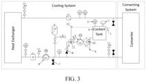
- a cooling system comprises a heat exchanger, a converter, and a liquid cooling pipeline connecting the heat exchanger with the converter.
- a circulation pump 8 is provided in the liquid cooling pipeline.
- the cooling system further comprises a coolant tank 4, an injection pump 5 and a control unit.
- the coolant tank 4 is used to store a coolant (such as a liquid coolant) and the coolant tank 4 is equipped with a liquid level sensor 3.
- the liquid level sensor 3 real-timely detects the liquid level of the coolant tank 4.
- the injection pump 5 is connected to the coolant tank 4 and used to inject the coolant from the coolant tank 4 into the liquid cooling pipeline during its operation.
- the coolant-injection means of the cooling system may be integrated into the cooling system, and the injection operation is controlled by the control unit of the cooling system.
- the liquid level sensor 3 is provided to detect the liquid level of the coolant within the coolant tank 4, thereby determining whether the amount of the coolant in the coolant tank 4 satisfies the requirement for injection.
- the respiration valve 2 communicates inside and outside of the coolant tank 4, such that the coolant in the coolant tank 4 can automatically flow into the injection pump 5 under action of gravity to complete the filling of the pump.
- the cooling system realizes an automatic filling of the injection pump in the initial coolant-injection, and then turns on the injection process according to judgement to the detected pressure in a cooling loop, thereby realizing the automatic injection of the cooling system.
- control unit is configured to, when the circulation pump 8 is turned off (i.e., the coolant in the liquid cooling pipeline is in a static state), turn on the injection pump 5 when the pressure of the coolant in the liquid cooling pipeline is less than a lower static hydraulic threshold so as to supplement the coolant to the liquid cooling pipeline , allowing the pressure of the coolant to be continuously increased; and turn off the injection pump 5 when the pressure of the coolant reaches an upper static hydraulic threshold.
- the cooling system comprises a temperature sensor.
- the temperature sensor is disposed on the liquid cooling pipeline and used to monitor temperature of the coolant at a inlet end of the converter, and output a temperature detection signal to the control unit.
- the control unit is configured to turn on the injection pump 5, and when the temperature of the coolant reaches the upper operating temperature threshold, and the pressure of the coolant is less than the upper dynamic hydraulic threshold, so as to supplement the coolant to the liquid cooling pipeline to allow the pressure of the coolant to be continuously increased.
- the control unit is configured to turn off the injection pump 5 so that the heat dissipation capability of the cooling system can be quickly improved.
- the first three-way valve 10 and the second three-way valve 11 are switched to communicate the pipes c and b. Coolant is added into the coolant tank 4 via the inlet port 1, and then automatically flows into the injection pump 5 under action of gravity until there is coolant flowing back to the coolant tank 4 through a pipe 12. Thus, the coolant-injection operation for the injection pump 5 is completed.
- the automatic coolant-injection operation for the coolant tank 4 begins.
- a hose 9 is connected to an external coolant source.
- the control unit automatically switches the first three-way valve 10 to a pipe a.
- the injection pump 5 is turned on to transmit the coolant to the coolant tank 4 through the pipes a and b until the liquid level is higher than the upper liquid level threshold.
- the injection pump 5 is turned off, and the first three-way valve 10 and the second three-way valve 11 are switched to communicate the pipes c and b.
- the automatic coolant-adding operation for the coolant tank 4 is completed.
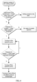
- the flow diagram illustratively shows the coolant-injection operation for the cooling system.
- the coolant tank 4 is added with coolant, and the liquid level sensor 3 detects the liquid level of the coolant tank 4.
- the injection pump 5 is turned on to perform coolant-injection.
- the circulation pump 8 operates according to a preset on-off cycle to exhaust gas/air from the pipeline.
- the injection pump 5 is turned off and a low liquid level alarm can be sent, and adding coolant to the coolant tank 4.
- control unit when the circulation pump 8 is turned off, the control unit is configured to turn on the injection pump 5 when the pressure of the coolant in the liquid cooling pipeline is less than the lower static hydraulic threshold so as to supplement coolant to the liquid cooling pipeline.
- the pressure of the coolant continuously increases.
- the control unit is configured to turn off the injection pump 5.
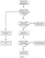
- the flow diagram illustratively shows coolant supplementing operation of the cooling system.
- the injection pump When the liquid level of the coolant tank 4 is greater than the lower liquid level threshold and the pressure of the coolant is less than a preset lower pressure threshold at the current operating state, the injection pump is turned on. When the pressure of the coolant reaches a preset upper pressure threshold at the current operating state, the injection pump is turned off. When the liquid level of the coolant tank 4 is less than the lower liquid level threshold, the low liquid level alarm is sent and the coolant tank 4 is added with coolant.
- the control unit determines the upper and lower dynamic hydraulic thresholds and the upper and lower static hydraulic thresholds according to the operating states of the circulation pump, thereby ensuring the pressure of the pipeline within a normal demand range.
- the control unit real-timely monitors the temperature of the coolant in the pipeline, for example, by use of one or more temperature sensors.
- the coolant-supplementing operation is performed to make the pipeline pressure to the maximum upper threshold, thereby improving heat dissipation capability of the cooling system, and ensuring full power operation of the device.
- the upper dynamic hydraulic threshold can be set depending on different temperature ranges.
- the coolant supplementing operation can be performed in either the turning-on or turning-off state of the device.
- the control unit switches the first three-way valve 10 and the second three-way valve 11, and thus forms a fluid loop.
- the fluid loop sequentially includes an external coolant source, the first three-way valve 10, the injection pump 5, the second three-way valve 11, and the coolant tank 4.
- the control unit is configured to turn on the injection pump 5 to automatically add coolant to the coolant tank 4.
- the liquid level of the coolant tank 4 reaches the upper liquid level threshold, the automatic coolant adding operation for the coolant tank 4 is completed.
- the control unit is then configured to turn off the injection pump 5 and to switch the first three-way valve 10 and the second three-way valve 11 to form a fluid loop.
- the fluid loop includes the coolant tank 4, the first three-way valve 10, the injection pump 5, the second three-way valve 11, and the liquid cooling pipeline in sequence.
Landscapes
- Engineering & Computer Science (AREA)
- Physics & Mathematics (AREA)
- Microelectronics & Electronic Packaging (AREA)
- Thermal Sciences (AREA)
- General Engineering & Computer Science (AREA)
- Mechanical Engineering (AREA)
- Automation & Control Theory (AREA)
- General Physics & Mathematics (AREA)
- Manufacturing & Machinery (AREA)
- Chemical & Material Sciences (AREA)
- Chemical Kinetics & Catalysis (AREA)
- Electrochemistry (AREA)
- General Chemical & Material Sciences (AREA)
- Cooling Or The Like Of Electrical Apparatus (AREA)
- Heat Treatments In General, Especially Conveying And Cooling (AREA)
Claims (15)
- Ein Kühlsystem, das Folgendes umfasst:einen Wärmetauscher;einen Umrichter;eine Flüssigkeitskühlleitung zur Verbindung des Wärmetauschers mit dem Umrichter, wobei die Flüssigkeitskühlleitung mit einer Umwälzpumpe (8) versehen ist;einen Kühlmitteltank (1) zum Speichern eines Kühlmittels, wobei der Kühlmitteltank (1) einen Flüssigkeitspegelsensor (3) zum Erfassen eines Flüssigkeitspegels des Kühlmitteltanks (1) umfasst; undeine Steuereinheit zur Steuerung der Ein- und Ausschaltvorgänge der Umwälzpumpe (8),das Kühlsystem dadurch gekennzeichnet ist, dass es außerdem umfasst:eine Einspritzpumpe (5), die mit dem Kühlmitteltank (1) verbunden ist, um das Kühlmittel aus dem Kühlmitteltank (1) in die Flüssigkeitskühlleitung einzuspritzen, wenn die Einspritzpumpe (5) eingeschaltet ist;wobei die Steuereinheit dazu eingerichtet ist,Einschalt- und Ausschaltvorgänge der Einspritzpumpe (5) zu steuern und einen dynamischen hydraulischen Schwellenwert und einen statischen hydraulischen Schwellenwert entsprechend den jeweiligen Zuständen des Kühlmittels in der Flüssigkeitskühlleitung einzustellen,wenn der Flüssigkeitspegel im Kühlmitteltank (1) einen oberen Schwellenwert für den Flüssigkeitspegel erreicht, die Einspritzpumpe (5) einschalten, so dass das Kühlmittel durch die Einspritzpumpe (5) in die Flüssigkeitskühlleitung eingespritzt wird; undwenn der Druck des Kühlmittels in der Flüssigkeitskühlleitung einen oberen statischen hydraulischen Schwellenwert erreicht, die Einspritzpumpe (5) auszuschalten und die Ein- und Ausschaltvorgänge der Umwälzpumpe (8) mit einer voreingestellten Umwälzdauer auszuführen, wobei die Umwälzpumpe (8) das Kühlmittel zwingt, in der Flüssigkeitskühlleitung zu zirkulieren, wenn sie eingeschaltet wird.
- Das Kühlsystem nach Anspruch 1, dadurch gekennzeichnet, dass der Kühlmitteltank (1) ferner mit einem Atmungsventil versehen ist, das eine Verbindung zwischen dem Inneren und dem Äußeren des Kühlmitteltanks (1) herstellt, so dass das Kühlmittel im Kühlmitteltank (1) automatisch in die Einspritzpumpe (5) fließen kann.
- Das Kühlsystem nach Anspruch 1 oder 2, dadurch gekennzeichnet, dass der Kühlmitteltank (1) ferner mit einer Einlassöffnung (1) zur Durchführung einer Kühlmittelzugabe für den Kühlmitteltank (1) versehen ist.
- Das Kühlsystem nach einem der Ansprüche 1 bis 3, dadurch gekennzeichnet, dass das Kühlsystem weiterhin umfasst:ein erstes Dreiwegeventil (10), dessen erstes Ende mit dem Kühlmitteltank (1), dessen zweites Ende mit der Einspritzpumpe (5) und dessen drittes Ende mit einer externen Kühlmittelquelle verbunden ist; undein zweites Dreiwegeventil (11), dessen erstes Ende mit der Einspritzpumpe (5), dessen zweites Ende mit der Flüssigkeitskühlleitung und dessen drittes Ende mit dem Kühlmitteltank (4) verbunden ist.
- Das Kühlsystem nach einem der Ansprüche 1 bis 4, dadurch gekennzeichnet, dass das Kühlsystem ferner einen Temperatursensor umfasst, der an der Flüssigkeitskühlleitung angeordnet ist, wobei der Temperatursensor eine Temperatur des Kühlmittels an einem Einlassende des Umrichters überwacht und ein Temperaturerfassungssignal an die Steuereinheit ausgibt,
wobei die Steuereinheit dazu eingerichtet ist, wenn die Umwälzpumpe (8) eingeschaltet wird,die Einspritzpumpe (5) einzuschalten, wenn die Temperatur des Kühlmittels einen oberen Betriebstemperaturschwellenwert erreicht und der Druck des Kühlmittels unter einem oberen dynamischen hydraulischen Schwellenwert liegt, um Kühlmittel in die Flüssigkeitskühlleitung zu leiten und den Druck des Kühlmittels kontinuierlich zu erhöhen, unddie Einspritzpumpe (5) abzuschalten, wenn der Druck des Kühlmittels den oberen dynamischen hydraulischen Schwellenwert erreicht. - Das Kühlsystem nach einem der Ansprüche 1 bis 5, dadurch gekennzeichnet, dass das Kühlsystem ferner ein Einwegventil (6) umfasst, das zwischen der Einspritzpumpe (5) und der Flüssigkeitskühlleitung angeschlossen ist, um zu verhindern, dass das Kühlmittel in der Flüssigkeitskühlleitung zum Kühlmitteltank (4) zurückfließt.
- Das Kühlsystem nach einem der Ansprüche 1 bis 6, dadurch gekennzeichnet, dass die Flüssigkeitskühlleitung außerdem mit einem Ablassventil versehen ist.
- Ein automatisches Kühlmitteleinspritzverfahren für ein Kühlsystem nach einem der Ansprüche 1 bis 7,
dadurch gekennzeichnet, dass das Verfahren umfasst:das Bereitstellen eines Kühlmitteltanks (4) und das Durchführen eines Kühlmittelhinzufügungsvorgangs für den Kühlmitteltank (4);das Anordnen eines Flüssigkeitspegelsensors (3) am Kühlmitteltank (4) zur Erfassung eines Flüssigkeitspegels im Kühlmitteltank (4);das Bereitstellen einer Einspritzpumpe (5), die mit dem Kühlmitteltank (4) verbunden ist, um Kühlmittel aus dem Kühlmitteltank (4) in die Flüssigkeitskühlleitung einzuspritzen, wenn die Einspritzpumpe (5) eingeschaltet ist; unddas Bereitstellen einer Steuereinheit zum Steuern des Ein- und Ausschaltvorgangs der Einspritzpumpe (5) und des Ein- und Ausschaltvorgangs der Umwälzpumpe (8) und das Einstellen eines dynamischen hydraulischen Schwellenwerts und eines statischen hydraulischen Schwellenwerts entsprechend den Zuständen des Kühlmittels in der Flüssigkeitskühlleitung,wobei die Steuereinheit dazu eingerichtet ist,wenn der Flüssigkeitspegel im Kühlmitteltank (4) einen oberen Schwellenwert für den Flüssigkeitspegel erreicht, die Einspritzpumpe (5) einzuschalten, so dass das Kühlmittel durch die Einspritzpumpe (5) in die Flüssigkeitskühlleitung eingespritzt wird; undwenn ein Druck des Kühlmittels in der Flüssigkeitskühlleitung einen oberen statischen hydraulischen Schwellenwert erreicht, die Einspritzpumpe (5) auszuschalten und die Ein- und Ausschaltvorgänge der Umwälzpumpe (8) mit einer voreingestellten Umwälzperiode auszuführen, wobei die Umwälzpumpe (8) das Kühlmittel zwingt, in der Flüssigkeitskühlleitung zu zirkulieren, wenn sie eingeschaltet wird. - Das Verfahren nach Anspruch 8, dadurch gekennzeichnet, dass das Kühlsystem ferner ein erstes Dreiwegeventil (10) und ein zweites Dreiwegeventil (11) umfasst, und der Schritt des Durchführens des Kühlmittelhinzufügungsvorgangs für den Kühlmitteltank (4) umfasst:das Schalten des ersten Dreiwegeventils (10) und des zweiten Dreiwegeventils (11) durch die Steuereinheit und das Bilden eines Fluidkreislaufs, der den Kühlmitteltank (4), das erste Dreiwegeventil (10), die Einspritzpumpe (5), das zweite Dreiwegeventil und den Kühlmitteltank (4) nacheinander umfasst;das Hinzufügen des Kühlmittels in den Kühlmitteltank (4) über eine am Kühlmitteltank (4) angeordnete Einlassöffnung (1); unddas automatische Fließenlassen des Kühlmittels im Kühlmitteltank (4) über das erste Dreiwegeventil (10) in die Einspritzpumpe (5), bis das Kühlmittel in den Kühlmitteltank (4) zurückfließt, um das Füllen der Einspritzpumpe (5) abzuschließen.
- Das Verfahren nach Anspruch 8 oder 9, dadurch gekennzeichnet, dass das Kühlsystem ferner ein erstes Dreiwegeventil (10) und ein zweites Dreiwegeventil (11) umfasst, und dass der Schritt des Durchführens des Kühlmittelhinzufügungsvorgangs für den Kühlmitteltank (4) umfasst:das Schalten des ersten Dreiwegeventils (10) und des zweiten Dreiwegeventils (11) durch die Steuereinheit und das Bilden eines Fluidkreislaufs, der eine externe Kühlmittelquelle, das erste Dreiwegeventil (10), die Einspritzpumpe (5), das zweite Dreiwegeventil und den Kühlmitteltank (4) nacheinander einschließt; unddas Einschalten der Einspritzpumpe (5), um dem Kühlmitteltank (4) automatisch Kühlmittel hinzuzufügen, bis der Flüssigkeitspegel des Kühlmitteltanks (4) die obere Flüssigkeitspegelschwelle erreicht, wobei die Steuereinheit dazu eingerichtet ist, dann die Einspritzpumpe (5) auszuschalten und das erste Dreiwegeventil (10) und das zweite Dreiwegeventil (11) zu schalten, um einen Fluidkreislauf zu bilden, der den Kühlmitteltank (4), das erste Dreiwegeventil (10), die Einspritzpumpe (5), das zweite Dreiwegeventil und die Flüssigkeitskühlleitung nacheinander umfasst.
- Das Verfahren nach einem der Ansprüche 8 bis 10, dadurch gekennzeichnet, dass das Verfahren ferner umfasst:
das Konfigurieren der Steuereinheit zum Abschalten der Einspritzpumpe (5) und zum automatischen Hinzufügen von Kühlmittel in den Kühlmitteltank (4), wenn der Flüssigkeitspegel im Kühlmitteltank (4) unter einem unteren Schwellenwert für den Flüssigkeitspegel liegt. - Das Verfahren nach einem der Ansprüche 8 bis 11, dadurch gekennzeichnet, dass das Verfahren ferner umfasst:
die Steuereinheit so einzurichten, dass sie beim Einschalten der Umwälzpumpe (8):die Einspritzpumpe (5) einschalt, wenn der Druck des Kühlmittels in der Flüssigkeitskühlleitung unter einem unteren dynamischen hydraulischen Schwellenwert liegt, um der Flüssigkeitskühlleitung Kühlmittel zuzuführen und den Druck des Kühlmittels kontinuierlich zu erhöhen, unddie Einspritzpumpe (5) abschaltet, wenn der Druck des Kühlmittels einen oberen dynamischen hydraulischen Schwellenwert erreicht. - Das Verfahren nach einem der Ansprüche 8 bis 12, dadurch gekennzeichnet, dass das Verfahren ferner umfasst:
die Steuereinheit so einzurichten, dass sie beim Ausschalten der Umwälzpumpe (8):die Einspritzpumpe (5) einschaltet, wenn der Druck des Kühlmittels in der Flüssigkeitskühlleitung unter einem unteren statischen hydraulischen Schwellenwert liegt, um der Flüssigkeitskühlleitung Kühlmittel zuzuführen und den Druck des Kühlmittels kontinuierlich zu erhöhen, unddie Einspritzpumpe (5) abschaltet, wenn der Druck des Kühlmittels die obere statische Hydraulikschwelle erreicht. - Das Verfahren nach einem der Ansprüche 8 bis 13, dadurch gekennzeichnet, dass das Kühlsystem ferner einen Temperatursensor umfasst, der an der Flüssigkeitskühlleitung angeordnet ist, um eine Temperatur des Kühlmittels an einem Einlassende des Umrichters zu überwachen und ein Temperaturerfassungssignal an die Steuereinheit auszugeben; und
wobei die Steuereinheit dazu eingerichtet ist, wenn die Umwälzpumpe (8) eingeschaltet wird:die Einspritzpumpe (5) einzuschalten, wenn die Temperatur des Kühlmittels einen oberen Betriebstemperaturschwellenwert erreicht und der Druck des Kühlmittels unter einem oberen dynamischen hydraulischen Schwellenwert liegt, um Kühlmittel in die Flüssigkeitskühlleitung zu leiten und den Druck des Kühlmittels kontinuierlich zu erhöhen, unddie Einspritzpumpe abzuschalten, wenn der Druck des Kühlmittels den oberen dynamischen hydraulischen Schwellenwert erreicht. - Das Verfahren nach einem der Ansprüche 8 bis 15, dadurch gekennzeichnet, dass das Verfahren ferner umfasstwenn die Umwälzpumpe (8) eingeschaltet ist, das Sammeln von Gas in der Flüssigkeitskühlleitung zusammen mit der Zirkulation des Kühlmittels; undwenn die Umwälzpumpe (8) abgeschaltet ist, das Ablassen des gesammelten Gases über ein an der Flüssigkeitskühlleitung angeordnetes Ablassventil.
Applications Claiming Priority (1)
| Application Number | Priority Date | Filing Date | Title |
|---|---|---|---|
| CN202011409847.7A CN114599195B (zh) | 2020-12-04 | 2020-12-04 | 可实现自动注液功能的冷却系统及自动注液方法 |
Publications (3)
| Publication Number | Publication Date |
|---|---|
| EP4013202A1 EP4013202A1 (de) | 2022-06-15 |
| EP4013202B1 true EP4013202B1 (de) | 2025-07-09 |
| EP4013202C0 EP4013202C0 (de) | 2025-07-09 |
Family
ID=78819978
Family Applications (1)
| Application Number | Title | Priority Date | Filing Date |
|---|---|---|---|
| EP21211237.9A Active EP4013202B1 (de) | 2020-12-04 | 2021-11-30 | Kühlsystem und automatisches kühlmitteleinspritzverfahren für das kühlsystem |
Country Status (4)
| Country | Link |
|---|---|
| US (1) | US11859923B2 (de) |
| EP (1) | EP4013202B1 (de) |
| CN (1) | CN114599195B (de) |
| TW (1) | TWI789126B (de) |
Families Citing this family (7)
| Publication number | Priority date | Publication date | Assignee | Title |
|---|---|---|---|---|
| CN116321910A (zh) * | 2021-12-03 | 2023-06-23 | 华为技术有限公司 | 液冷结构及电子装置 |
| CN117812875A (zh) * | 2022-09-23 | 2024-04-02 | 中兴通讯股份有限公司 | 液冷系统及其控制方法 |
| US12419008B2 (en) * | 2023-04-28 | 2025-09-16 | Hewlett Packard Enterprise Development Lp | Immersion cooling using cooling containers for an electronic device |
| CN116568005B (zh) * | 2023-05-19 | 2025-09-16 | 苏州浪潮智能科技有限公司 | 数据中心液冷换热系统、服务器和数据中心液冷换热方法 |
| CN117366726B (zh) * | 2023-10-17 | 2024-09-17 | 宁波奥克斯电气股份有限公司 | 一种液冷机组、自动加液方法、半自动加液方法及补液方法 |
| CN118073723B (zh) * | 2024-03-12 | 2025-09-05 | 浙江海得智慧能源有限公司 | 一种储能液冷系统快速注液方法及储能液冷系统 |
| CN118574394B (zh) * | 2024-07-22 | 2025-01-28 | 深圳市度信科技有限公司 | 一种支持自动注液的液冷装置 |
Family Cites Families (14)
| Publication number | Priority date | Publication date | Assignee | Title |
|---|---|---|---|---|
| CN201590978U (zh) * | 2009-11-27 | 2010-09-22 | 艾默生网络能源有限公司 | 一种注液排气装置 |
| US9217690B2 (en) * | 2012-01-25 | 2015-12-22 | GM Global Technology Operations LLC | Coolant loss detection and remediation in a liquid cooled battery pack |
| CN103929016A (zh) * | 2014-04-28 | 2014-07-16 | 中船重工(重庆)海装风电设备有限公司 | 一种海上风力发电机组水冷系统 |
| CN205283375U (zh) * | 2015-12-29 | 2016-06-01 | 新疆金风科技股份有限公司 | 功率模块的冷却装置 |
| US11452243B2 (en) | 2017-10-12 | 2022-09-20 | Coolit Systems, Inc. | Cooling system, controllers and methods |
| CN108736765B (zh) * | 2018-05-22 | 2021-08-10 | 太原理工大学 | 一种变频一体机自控水冷散热装置 |
| CN108678911B (zh) | 2018-05-28 | 2024-06-04 | 维翰(大连)工业设备有限公司 | 一种风力发电机的冷却装置 |
| CN209159450U (zh) * | 2018-09-11 | 2019-07-26 | 山东鲁能智能技术有限公司 | 一种自动补液的液冷充电桩 |
| JPWO2020084656A1 (ja) * | 2018-10-22 | 2021-09-16 | 東芝三菱電機産業システム株式会社 | 水冷式電力変換システム |
| CN209797470U (zh) | 2019-03-27 | 2019-12-17 | 湖南铁路科技职业技术学院 | 一种变流器冷却液加注装置 |
| CN110411680B (zh) * | 2019-06-28 | 2021-08-03 | 西安中车永电电气有限公司 | 一种用于密闭式液冷系统的注排液及压力检测装置 |
| CN110662400A (zh) | 2019-09-29 | 2020-01-07 | 中车青岛四方车辆研究所有限公司 | 变流器冷却系统及变流器冷却系统控制方法 |
| WO2021140991A1 (ja) * | 2020-01-06 | 2021-07-15 | 株式会社デンソー | 冷却制御装置、冷却システム、プログラム及び制御方法 |
| CN111828332B (zh) * | 2020-06-18 | 2022-05-27 | 蓝箭航天技术有限公司 | 用于航天发动机试验的灌泵系统 |
-
2020
- 2020-12-04 CN CN202011409847.7A patent/CN114599195B/zh active Active
-
2021
- 2021-11-18 US US17/455,660 patent/US11859923B2/en active Active
- 2021-11-19 TW TW110143237A patent/TWI789126B/zh active
- 2021-11-30 EP EP21211237.9A patent/EP4013202B1/de active Active
Also Published As
| Publication number | Publication date |
|---|---|
| TWI789126B (zh) | 2023-01-01 |
| CN114599195B (zh) | 2025-04-04 |
| CN114599195A (zh) | 2022-06-07 |
| EP4013202C0 (de) | 2025-07-09 |
| US11859923B2 (en) | 2024-01-02 |
| EP4013202A1 (de) | 2022-06-15 |
| TW202223326A (zh) | 2022-06-16 |
| US20220178631A1 (en) | 2022-06-09 |
Similar Documents
| Publication | Publication Date | Title |
|---|---|---|
| EP4013202B1 (de) | Kühlsystem und automatisches kühlmitteleinspritzverfahren für das kühlsystem | |
| Abrial | Steam-boiler control specification problem | |
| JP2010513840A (ja) | 貯蔵複合ボイラー | |
| CN110492137A (zh) | 一种燃料电池冷却循环系统及其工作方法 | |
| CN108897348B (zh) | 一种orc发电系统工质罐液位自动控制系统 | |
| CN210772442U (zh) | 一种热泵两联供系统 | |
| JP2008256346A (ja) | ヒートポンプ装置 | |
| CN212838193U (zh) | 一种风力发电机组冷却系统自动补水装置 | |
| CN212625678U (zh) | 一种燃料电池发动机水路温控系统 | |
| CN221299302U (zh) | 工程机械尿素喷嘴冷却装置及工程机械 | |
| JP2016065685A (ja) | ハイブリッド給湯システム | |
| JP2006017417A (ja) | 貯湯式給湯装置 | |
| JP2009210150A (ja) | 給湯システム | |
| JP2009174773A (ja) | コージェネレーションシステム | |
| CN210470110U (zh) | 一种采用双冷源的高压变频器冷却系统 | |
| CN212299405U (zh) | 一种家用储水式电热水器 | |
| JP6223136B2 (ja) | コージェネレーションシステム | |
| JP3773872B2 (ja) | 湯水混合ユニット | |
| CN220086097U (zh) | 一种燃料电池高位水箱加液系统 | |
| CN207207046U (zh) | 一种注塑机油箱油温自动检测装置 | |
| KR101987293B1 (ko) | 온수 공급장치 및 그 제어방법 | |
| CN220552000U (zh) | 内循环采暖炉智能加水装置 | |
| CN116045327B (zh) | 防倒油烟装置、系统以及防倒油烟装置的控制方法 | |
| JP2008116146A (ja) | ヒートポンプ式給湯機 | |
| JP7781714B2 (ja) | 風呂装置、及びその制御方法 |
Legal Events
| Date | Code | Title | Description |
|---|---|---|---|
| PUAI | Public reference made under article 153(3) epc to a published international application that has entered the european phase |
Free format text: ORIGINAL CODE: 0009012 |
|
| STAA | Information on the status of an ep patent application or granted ep patent |
Free format text: STATUS: THE APPLICATION HAS BEEN PUBLISHED |
|
| AK | Designated contracting states |
Kind code of ref document: A1 Designated state(s): AL AT BE BG CH CY CZ DE DK EE ES FI FR GB GR HR HU IE IS IT LI LT LU LV MC MK MT NL NO PL PT RO RS SE SI SK SM TR |
|
| STAA | Information on the status of an ep patent application or granted ep patent |
Free format text: STATUS: REQUEST FOR EXAMINATION WAS MADE |
|
| 17P | Request for examination filed |
Effective date: 20221025 |
|
| RBV | Designated contracting states (corrected) |
Designated state(s): AL AT BE BG CH CY CZ DE DK EE ES FI FR GB GR HR HU IE IS IT LI LT LU LV MC MK MT NL NO PL PT RO RS SE SI SK SM TR |
|
| RAP3 | Party data changed (applicant data changed or rights of an application transferred) |
Owner name: DELTA ELECTRONICS (SHANGHAI) CO., LTD. |
|
| RAP3 | Party data changed (applicant data changed or rights of an application transferred) |
Owner name: DELTA ELECTRONICS (SHANGHAI) CO., LTD. |
|
| GRAP | Despatch of communication of intention to grant a patent |
Free format text: ORIGINAL CODE: EPIDOSNIGR1 |
|
| STAA | Information on the status of an ep patent application or granted ep patent |
Free format text: STATUS: GRANT OF PATENT IS INTENDED |
|
| RIC1 | Information provided on ipc code assigned before grant |
Ipc: H01M 10/6568 20140101ALI20250217BHEP Ipc: F28F 27/00 20060101ALI20250217BHEP Ipc: F28D 21/00 20060101ALI20250217BHEP Ipc: F28D 15/00 20060101ALI20250217BHEP Ipc: H05K 7/20 20060101AFI20250217BHEP |
|
| INTG | Intention to grant announced |
Effective date: 20250228 |
|
| GRAS | Grant fee paid |
Free format text: ORIGINAL CODE: EPIDOSNIGR3 |
|
| GRAA | (expected) grant |
Free format text: ORIGINAL CODE: 0009210 |
|
| STAA | Information on the status of an ep patent application or granted ep patent |
Free format text: STATUS: THE PATENT HAS BEEN GRANTED |
|
| AK | Designated contracting states |
Kind code of ref document: B1 Designated state(s): AL AT BE BG CH CY CZ DE DK EE ES FI FR GB GR HR HU IE IS IT LI LT LU LV MC MK MT NL NO PL PT RO RS SE SI SK SM TR |
|
| REG | Reference to a national code |
Ref country code: GB Ref legal event code: FG4D |
|
| REG | Reference to a national code |
Ref country code: CH Ref legal event code: EP |
|
| REG | Reference to a national code |
Ref country code: IE Ref legal event code: FG4D |
|
| U01 | Request for unitary effect filed |
Effective date: 20250709 |
|
| U07 | Unitary effect registered |
Designated state(s): AT BE BG DE DK EE FI FR IT LT LU LV MT NL PT RO SE SI Effective date: 20250715 |
|
| U20 | Renewal fee for the european patent with unitary effect paid |
Year of fee payment: 5 Effective date: 20251127 |
|
| PG25 | Lapsed in a contracting state [announced via postgrant information from national office to epo] |
Ref country code: IS Free format text: LAPSE BECAUSE OF FAILURE TO SUBMIT A TRANSLATION OF THE DESCRIPTION OR TO PAY THE FEE WITHIN THE PRESCRIBED TIME-LIMIT Effective date: 20251109 |
|
| PGFP | Annual fee paid to national office [announced via postgrant information from national office to epo] |
Ref country code: GB Payment date: 20251121 Year of fee payment: 5 |
|
| PG25 | Lapsed in a contracting state [announced via postgrant information from national office to epo] |
Ref country code: NO Free format text: LAPSE BECAUSE OF FAILURE TO SUBMIT A TRANSLATION OF THE DESCRIPTION OR TO PAY THE FEE WITHIN THE PRESCRIBED TIME-LIMIT Effective date: 20251009 |
|
| PG25 | Lapsed in a contracting state [announced via postgrant information from national office to epo] |
Ref country code: HR Free format text: LAPSE BECAUSE OF FAILURE TO SUBMIT A TRANSLATION OF THE DESCRIPTION OR TO PAY THE FEE WITHIN THE PRESCRIBED TIME-LIMIT Effective date: 20250709 |
|
| PG25 | Lapsed in a contracting state [announced via postgrant information from national office to epo] |
Ref country code: GR Free format text: LAPSE BECAUSE OF FAILURE TO SUBMIT A TRANSLATION OF THE DESCRIPTION OR TO PAY THE FEE WITHIN THE PRESCRIBED TIME-LIMIT Effective date: 20251010 |
|
| PG25 | Lapsed in a contracting state [announced via postgrant information from national office to epo] |
Ref country code: PL Free format text: LAPSE BECAUSE OF FAILURE TO SUBMIT A TRANSLATION OF THE DESCRIPTION OR TO PAY THE FEE WITHIN THE PRESCRIBED TIME-LIMIT Effective date: 20250709 |
|
| PG25 | Lapsed in a contracting state [announced via postgrant information from national office to epo] |
Ref country code: RS Free format text: LAPSE BECAUSE OF FAILURE TO SUBMIT A TRANSLATION OF THE DESCRIPTION OR TO PAY THE FEE WITHIN THE PRESCRIBED TIME-LIMIT Effective date: 20251009 |
|
| PG25 | Lapsed in a contracting state [announced via postgrant information from national office to epo] |
Ref country code: ES Free format text: LAPSE BECAUSE OF FAILURE TO SUBMIT A TRANSLATION OF THE DESCRIPTION OR TO PAY THE FEE WITHIN THE PRESCRIBED TIME-LIMIT Effective date: 20250709 |