EP4012339B1 - Vorrichtung und verfahren zur navigationsroutenplanung - Google Patents
Vorrichtung und verfahren zur navigationsroutenplanung Download PDFInfo
- Publication number
- EP4012339B1 EP4012339B1 EP20212730.4A EP20212730A EP4012339B1 EP 4012339 B1 EP4012339 B1 EP 4012339B1 EP 20212730 A EP20212730 A EP 20212730A EP 4012339 B1 EP4012339 B1 EP 4012339B1
- Authority
- EP
- European Patent Office
- Prior art keywords
- waypoint
- navigation
- waypoints
- indicator
- indicator graphic
- Prior art date
- Legal status (The legal status is an assumption and is not a legal conclusion. Google has not performed a legal analysis and makes no representation as to the accuracy of the status listed.)
- Active
Links
Images




Classifications
-
- G—PHYSICS
- G01—MEASURING; TESTING
- G01C—MEASURING DISTANCES, LEVELS OR BEARINGS; SURVEYING; NAVIGATION; GYROSCOPIC INSTRUMENTS; PHOTOGRAMMETRY OR VIDEOGRAMMETRY
- G01C21/00—Navigation; Navigational instruments not provided for in groups G01C1/00 - G01C19/00
- G01C21/20—Instruments for performing navigational calculations
- G01C21/203—Instruments for performing navigational calculations specially adapted for water-borne vessels
-
- G—PHYSICS
- G06—COMPUTING OR CALCULATING; COUNTING
- G06F—ELECTRIC DIGITAL DATA PROCESSING
- G06F3/00—Input arrangements for transferring data to be processed into a form capable of being handled by the computer; Output arrangements for transferring data from processing unit to output unit, e.g. interface arrangements
- G06F3/01—Input arrangements or combined input and output arrangements for interaction between user and computer
- G06F3/048—Interaction techniques based on graphical user interfaces [GUI]
- G06F3/0484—Interaction techniques based on graphical user interfaces [GUI] for the control of specific functions or operations, e.g. selecting or manipulating an object, an image or a displayed text element, setting a parameter value or selecting a range
- G06F3/04847—Interaction techniques to control parameter settings, e.g. interaction with sliders or dials
-
- G—PHYSICS
- G08—SIGNALLING
- G08G—TRAFFIC CONTROL SYSTEMS
- G08G5/00—Traffic control systems for aircraft
- G08G5/20—Arrangements for acquiring, generating, sharing or displaying traffic information
- G08G5/21—Arrangements for acquiring, generating, sharing or displaying traffic information located onboard the aircraft
-
- G—PHYSICS
- G08—SIGNALLING
- G08G—TRAFFIC CONTROL SYSTEMS
- G08G5/00—Traffic control systems for aircraft
- G08G5/30—Flight plan management
- G08G5/32—Flight plan management for flight plan preparation
-
- G—PHYSICS
- G08—SIGNALLING
- G08G—TRAFFIC CONTROL SYSTEMS
- G08G5/00—Traffic control systems for aircraft
- G08G5/50—Navigation or guidance aids
- G08G5/53—Navigation or guidance aids for cruising
-
- G—PHYSICS
- G08—SIGNALLING
- G08G—TRAFFIC CONTROL SYSTEMS
- G08G5/00—Traffic control systems for aircraft
- G08G5/50—Navigation or guidance aids
- G08G5/55—Navigation or guidance aids for a single aircraft
Definitions
- the present invention generally relates to a navigation planning system for planning a navigation route.
- An Electronic Chart Display and Information System displays navigation route information for one or more vessels, where the one or more vessels are navigating through a water body, for example a river, or a sea or the like.
- the ECDIS displays a chart of a desired sea area on a display by performing software processing of electronic chart data.
- the ECDIS may comprise a touch sensitive display screen. Therefore, the navigation route can be set on the chart displayed on the touch display screen by touching desired locations on the chart.
- the navigation route is established by determining a navigation starting point (a starting point) and a navigation destination point (a destination point) of the vessel, and in an interval, determining one or more points called "waypoint" through which the vessel should pass. These waypoints must be accurately located to not cause obstruction to the vessel on the navigation route.
- Current navigation route planning systems set the navigation route by sequentially setting waypoints on the screen of the ECDIS apparatus. For example, in JP-PA-2018-150024 , the navigation route planning system generates a route line by connecting the sequentially selected previous waypoints to a current waypoint being entered. Further, in order to set the next waypoint from the latest set waypoint, only a guideline value is displayed at the position of a latest waypoint i.e., a current waypoint. Thus, in all such navigation systems discussed above, the waypoints are set one by one in order i.e. sequentially. Additionally, since the conventional navigation apparatus displays only a guideline value for finding the next waypoint, the best navigation route for the vessel cannot be obtained.
- a device, a method, and a non-transitory computer-readable medium for planning a navigation route for a vessel or an aircraft may be provided.
- the navigation planning device provides optimized route from a source to a destination for a vessel or an aircraft.
- processor capable of processing information in accordance with embodiments of the present invention.
- electronic equipment electronic devices
- devices electronic equipment monitored by the system in accordance with embodiments of the present invention.
- One of the objectives of the present invention is to determine new one or more waypoints more efficiently and more easily.
- the new one or more waypoints may be determined based on positional relationship with the previously set waypoints or old waypoints.
- a navigation planning device is proposed that receives a plurality of waypoints i.e.
- the navigation planning device is communicatively coupled with an electronic chart display and information system (ECDIS), which displays a map required to plan the navigation route, and where the ECDIS may comprise a touch screen display.
- ECDIS electronic chart display and information system
- a user inputs the plurality of waypoints in at least one of random order or in sequential order along with a navigation start point and a navigation destination point of the navigation route by touching desired locations, moving a cursor on the display panel, or by inputting numerical data on the map displayed on the touch screen display.
- the plurality of waypoints may not necessarily be route origination and route destination points but may be any passing point any arbitrary point may be used for setting up the navigation route.
- receiving the navigation start point, the navigation destination point, and the plurality of waypoints corresponds to receiving position data associated with at least one of the navigation start point, the navigation destination point, and the plurality of waypoints.
- the position data may be received by at least one of: touching the display panel, a cursor on the display panel, or by inputting numerical data.
- the navigation planning system determines the navigation route for a vessel to navigate in a water body (for example, ocean). In an example embodiment, the navigation planning system determines the navigation route for an aircraft.
- the navigation planning device displays the inputted plurality of waypoints along with the navigation source point and the navigation destination point on the display screen.
- a position of each waypoint of the plurality of waypoints is selected tentatively.
- the tentative position of each waypoint of the plurality of waypoints can be moved or adjusted in order to optimize the navigation route by simple drag and drop or by moving back and forth any of the waypoints on the display screen.
- the proposed navigation planning device allows the user to temporarily set several waypoints between the navigation start point and the navigation destination point, or for that matter between any two passing points, and then modify the set positions of waypoints to an optimum navigation route while overviewing the entire navigation route.
- the user inputs at least one passing point which corresponds to an arbitrary location or position on a navigation route.
- the arbitrary location or position may be either in the water body or on land.
- a passing point may be set as the navigation starting point, and the position of the plurality of waypoints may be determined between the passing point and the navigation destination point.
- the plurality of waypoints can be determined between the passing point and the navigation destination point.
- the plurality of waypoints can also be determined between two passing points set on the water body, such as the ocean.
- the navigation planning device determines a positional relationship between the one or more new waypoints and the previously set waypoints and displays the positional relationship.
- the positional relationship is used to display indicator data at a currently selected waypoint and at a candidate position selected for the next waypoint (or the new waypoint).
- the indicator data is used to connect one or more waypoints of the plurality of waypoints to determine the optimized navigation route.
- the navigation planning device uses different types of indicators to ensure accuracy during determination of the new waypoint. In this way, the navigation planning system allows easy and accurate determination of the waypoints and consequently enables determining an optimized navigation route.
- FIG. 1A is a schematic diagram that exemplarily illustrates working environment 100a of a navigation planning device 101, in accordance with an example embodiment.
- the navigation planning device 101 is installed at a vessel navigating in a water body.
- the navigation planning device 101 may be installed on an aircraft.
- the navigation planning device 101 installed on the vessel may be used to determine an optimized navigation route in the water body.
- the optimized navigation route ensures minimum travelling delay for a vessel on the navigation route in the water body.
- the water body may comprise a sea, an ocean, a river, or the like.
- the navigation planning device 101 may obtain inputs from a user 105, where the inputs may comprise location of a navigation start point, location of a navigation destination point, and candidate positions of a plurality of waypoints in between the navigation start point and the navigation destination point, where the candidate positions may be obtained in random order or in a sequential order starting from the navigation start point, and where the location may comprise position data such as longitude or latitude, direction data, or GPS coordinates, distance from start point, or the like
- the navigation planning device 101 is communicatively coupled with a user device 103, and a database 109, via a network 107.
- the user device 103 comprises an application 103a installed in it, where the application 103a displays different information associated with navigation for the user 105 operating the user device 103.
- the user device 103 may be any user accessible device such as a smartphone, a portable computer, a display unit, or the like.
- the user device 103 may include Electronic Chart Display and Information System (ECDIS).
- ECDIS Electronic Chart Display and Information System
- the user device 103 uses the application 103a to display different navigation information such as sea maps, tidal currents of the sea, or the like on a display screen of the user device 103.
- the user device 103 may be configured with a touch screen display.
- the database 109 may store updated navigation maps, latest information about the weather forecast, information about the tidal currents, nautical charts that may be used by the vessel for navigating in the water body and determining an optimized navigation route.
- the database 109 may further comprise dangerous locations in the water body such as location of a whirlpool or the like.
- the database 109 may comprise navigation data such as information on salinity, water temperature and air temperature, atmospheric pressure, and wind (speed, gusts, and direction), geographical location in terms of longitude and latitude of the vessel, or the like.
- the database 109 may also comprise updated navigation maps, latest information about the weather forecast, or the like that may be used by an aircraft.
- the database 109 may be embodied as a map database and may represent a compiled navigation database that may be used in or with the user device 103 to provide navigation and/or map-related functions to the user 105. In such a case, the database 109 may be downloaded or stored on the user device 103.
- the network 107 may comprise suitable logic, circuitry, and interfaces that may be configured to provide a plurality of network ports and a plurality of communication channels for transmission and reception of data, such as selected positions of navigation start point, navigation destination point, plurality of waypoints or the likes.
- Each network port may correspond to a virtual address (or a physical machine address) for transmission and reception of the communication data.
- the virtual address may be an Internet Protocol Version 4 (IPv4) (or an IPv6 address) and the physical address may be a Media Access Control (MAC) address.
- IPv4 Internet Protocol Version 4
- MAC Media Access Control
- the network 107 may be associated with an application layer for implementation of communication protocols based on one or more communication requests from at least one of the one or more communication devices.
- the communication data may be transmitted or received, via the communication protocols.
- wired and wireless communication protocols may include, but are not limited to, Transmission Control Protocol and Internet Protocol (TCP/IP), User Datagram Protocol (UDP), Hypertext Transfer Protocol (HTTP), File Transfer Protocol (FTP), ZigBee, EDGE, infrared (IR), IEEE 802.11, 802.16, cellular communication protocols, and/or Bluetooth (BT) communication protocols.
- TCP/IP Transmission Control Protocol and Internet Protocol
- UDP User Datagram Protocol
- HTTP Hypertext Transfer Protocol
- FTP File Transfer Protocol
- ZigBee ZigBee
- EDGE infrared
- IEEE 802.11, 802.16, cellular communication protocols and/or Bluetooth (BT) communication protocols.
- BT Bluetooth
- Examples of the network 107 may include, but are not limited to a wireless channel, a wired channel, a combination of wireless and wired channel thereof.
- the wireless or wired channel may be associated with a network standard which may be defined by one of a Local Area Network (LAN), a Personal Area Network (PAN), a Wireless Local Area Network (WLAN), a Wireless Sensor Network (WSN), Wireless Area Network (WAN), Wireless Wide Area Network (WWAN), a Long Term Evolution (LTE) network, a plain old telephone service (POTS), and a Metropolitan Area Network (MAN).
- the wired channel may be selected on the basis of bandwidth criteria. For example, an optical fiber channel may be used for a high bandwidth communication. Further, a coaxial cable-based or Ethernet-based communication channel may be used for moderate bandwidth communication.
- Some embodiments are based on the recognition that in order to determine the optimized navigation route, the plurality of waypoints must be accurately located so as not to cause obstruction to the navigation route.
- the navigation planning device 101 enables the user 105 to select the plurality of waypoints, where the plurality of waypoints is selected in a random order.
- the plurality of waypoints corresponds to candidate positions, which can be adjusted or deleted based on the requirement in real time to determine an optimized navigation route.
- the navigation planning device 101 enables the user 105 to adjust the location of each waypoint of the plurality of waypoints dynamically in order to determine the optimized navigation route.
- the location of each waypoint is adjusted by the user 105 on a user interface of the user device 103 of the navigation planning device 101.
- the locations may be adjusted by the user 105 remotely by using the user device 103 which is connected to the navigation planning device 101 via the network 107.
- the position of each waypoint of the plurality of waypoints can be adjusted by dragging and dropping position of each waypoint of the plurality of waypoint on the map by using the touch screen display.
- a detailed analysis of the proposed navigation planning device 101 is described below with respect to FIG. 1B .
- FIG. 1B illustrates a block diagram 100b of the navigation planning device 101, exemplarily illustrated in FIG. 1A , in accordance with an example embodiment.
- the navigation planning device 101 includes a processing part 113 configured to execute stored instructions, as well as a memory 111 that stores instructions that are executable by the processing part 113.
- the memory 111 is further configured to store a chart data for navigation, where the chart data may comprise map of the water body and other navigational information.
- the memory 111 can include random access memory (RAM), read only memory (ROM), flash memory, or any other suitable memory systems.
- the processing part 113 is connected through the bus 115 to the memory 111.
- the processing part 113 of the navigation planning device 101 includes a position specifying unit 117, a positional relation determination unit 119, an indicator display unit 121, an indicator format unit 123, and a route setting unit 125 that outputs a navigation route 127.
- the navigation planning device 101 comprises a display 129, where the display 129 is configured to display at least a part of the chart data.
- the display 129 is further configured to receive a navigation start point and a navigation destination point for a navigation route of the vessel or the aircraft.
- the display 129 is further configured to receive a plurality of waypoints between the navigation start point and the navigation destination point.
- the display 129 may be a touch screen display panel.
- the display 129 is configured to provide data obtained from the user 105 such as the navigation start point, the navigation destination point, the plurality of waypoints, or the like to the processing part 113 via the bus 115.
- the navigation planning device 101 includes the position specifying unit 117, the positional relation determination unit 119, the indicator display unit 121, the indicator format unit 123, and the route setting unit 125 that outputs the navigation route 127.
- the navigation planning device 101 is configured to use the position specifying unit 117, where the position specifying unit 117 is configured to receive the navigation start point and the navigation destination point for the navigation route of the vessel or the aircraft. Further, the position specifying unit 117 is configured to receive a plurality of waypoints between the navigation start point and the navigation destination point, where the plurality of waypoints is obtained in either random order or in sequential order starting from the navigation start point.
- the locations of the navigation start point, the plurality of waypoints, and the navigation destination point may be specified, by the user 105, on the map displayed on the touch screen display panel of the display 129 by directly touching at the specific locations or moving a cursor on the display panel, or by inputting numerical data on the map.
- the user 105 may use the user device 103 to remotely specify locations of the navigation start point, the plurality of waypoints, and the navigation destination point on the map displayed on the touch screen of the user device 103.
- the plurality of waypoints comprises one or more previously selected waypoints, a current waypoint, a passing point and one or more next way points. Further, in order to determine the optimized navigation route, a positional relationship between the plurality of waypoints is required.
- the navigation planning device 101 is configured to use the positional relation determination unit 119, where the positional relation determination unit 119 is configured to determine the positional relationship between the plurality of waypoints.
- the positional relationship is determined based on position data of the plurality of waypoints, where the position data may comprise longitude and latitude information associated with each waypoint of the plurality of waypoints.
- the navigation planning device 101 is further configured to use the indicator display unit 121, where the indicator display unit 121 is configured to determine indicator data corresponding to at least one waypoint of the plurality of waypoints, based on the positional relationship of the plurality of waypoints.
- the indicator display unit 121 further outputs the at least one waypoint and the corresponding at least one indicator data to the display 129 for display on the display panel.
- the indicator data comprises a first indicator data (or a current indicator data) corresponding to the current waypoint, where the first indicator data indicates a distance from the current waypoint. The distance from the current waypoint is displayed in a current waypoint area opposite the candidate position of the one or more of previously selected waypoints.
- the indicator data comprises a second indicator data (or a next indicator data) corresponding to the next waypoint, where the second indicator data indicates a distance from the next waypoint.
- the distance from the next waypoint is displayed in a next waypoint area opposite the candidate position of the current waypoint.
- the first indicator data and the second indicator data are displayed simultaneously.
- the indicator display unit 121 obtains different indicator data display formats (illustrated in FIGs. 3A-3F ) from an indicator format unit 123 and allows the user 105 to select any one of the different indicator data display formats.
- the indicator display unit 121 may also provide its output to the user device 103 via the network 107, where the output of the indicator display unit 121 may be displayed on the user device 103.
- the indicator display unit 121 is communicatively coupled with the route setting unit 125, where the route setting unit 125 is configured to determine the navigation route by connecting the navigation start point, one or more waypoints of the plurality of waypoints, and the navigation destination point.
- the route setting unit 125 uses the indicator data generated by the indicator display unit 121 to determine which one or more waypoints of the plurality of waypoints should be connected in order to determine the optimized navigation route 127.
- the optimized navigation route 127 is displayed on the display 129.
- the optimized navigation route may be displayed on the user device 103.
- the route setting unit 125 communicates directly with the user device 103 such as ECDIS through the network 107 to determine the optimized navigation route 127.
- the indicator data is used to indicate the positional relationship between the current waypoint and at least one waypoint of the one or more next waypoints of the plurality of waypoints.
- the indicator data is used to indicate changes in the positional relationship between the plurality of waypoints, when any of the previously selected corresponding waypoints is adjusted.
- indicator data ensures efficient and accurate selection of the one or more next waypoints based on the current waypoint and the one or more previously set waypoints.
- the navigation planning device 101 is configured to output data for displaying the indicator data in one or more formats.
- the processing part 113 uses the indicator format unit 123.
- the one or more formats for the indicator data may comprise plurality of dots arranged on on one or more lines placed at predetermined intervals in predetermined directions, where the predetermined intervals and directions maybe an angle that indicates degree of separation between the plurality of dots.
- the predetermined intervals and directions maybe an angle that indicates degree of separation between the plurality of dots.
- an angle that indicates degree of separation between the plurality of dots In another indicator data display plurality of dots are arranged concentrically at predetermined intervals in one or more directions around a waypoint. Other different formats of the indicator data are described with respect to FIGs. 3A-3F .
- the navigation planning device 101 comprises a memory 111 configured to store a chart data for navigation, a display 129 configured to: display at least a part of the chart data on a display panel and further, receive a navigation start point and a navigation destination point for a navigation route of at least one of a vessel or an aircraft.
- the display 129 is further configured to receive a plurality of waypoints between the navigation start point and the navigation destination point, where the plurality of waypoints is received in at least one type of order, and where the at least one type of order comprises a random order or a sequential order.
- the navigation start points, and the navigation end point are passing points only.
- the display 129 is configured to display the at least one waypoint data and the corresponding at least one indicator data for the navigation route on the display panel.
- FIG.s 2A-2D provides a detailed description of the user interface used to input position data either through the display 129 or the user device 103.
- FIG. 2A illustrates a user interface 200a to input a navigation start point 201, a navigation destination points 203, and a plurality of waypoints 205a-205e in a navigation map, in accordance with an example embodiment.
- the user 105 may first input the navigation start point 201 and the navigation destination point 203 by touching at specific locations, moving the cursor on the display panel, or by inputting numerical data in the navigation map displayed on the user interface 200a. For example, the user 105 may select Liverpool as the navigation start point 201 and Birmingham as the navigation destination point 203.
- the navigation start point 201 may be represented by letter "S” and the navigation destination point 203 may be represented by letter “D", thus, enabling the user 105 to separate the navigation start point 201 and the navigation destination point 203 from the plurality of waypoints 205a-205e.
- the user 105 may select random locations for the plurality of waypoints 205a-205e between the navigation start point 201 and the navigation destination point 203 on the navigation map.
- the locations of the plurality of waypoints 205a-205e may be selected in a sequential order starting from the navigation start point 201.
- the selected locations are candidate locations (or tentative locations) of the plurality of waypoints, where the tentative location of any waypoint of the plurality of waypoints 205a-205e may be adjusted by moving or deleting any waypoint in order to determine the optimized navigation route.
- the optimized navigation route is determined by connecting the navigation start point 201 to the navigation destination point 203 via one or more waypoints of the plurality of waypoints 205a-205e.
- an intermediate navigation route from S to the waypoint 205b is determined.
- the waypoint 205b is the current waypoint
- 205a is a previously selected waypoint
- the waypoints 205c-205e are next waypoints which are not yet considered or connected in the navigation route.
- the navigation planning device 101 enables the user 105 to adjust any of the current waypoint 205b, previously selected waypoints 205a, and the next waypoints 205c-205e to plan the optimized navigation route for the vessel.
- an arbitrary position either in the water body or in the land may be selected as a passing point.
- the passing point may be set as the navigation starting point 201, and the position of the plurality of waypoints 205a-205e can be determined between the passing point and the navigation destination point 203.
- point 205b may be selected as the passing point and the plurality of waypoints 205c-205e can be determined between the passing point 205b and the navigation destination point 203.
- points 205e and 205a may be selected as two passing points and the plurality of waypoints 205a-205e can also be determined between two passing points 205e and 205a set on the ocean.
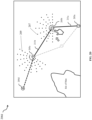
- FIG. 2B illustrates a user interface 200b, where the position of the waypoint 205b of the plurality of waypoints 205a-205e is changed in the navigation map, in accordance with an example, not falling under the claimed invention.
- an intermediate route from the navigation start point 201 to the waypoint 205c is determined.
- the position of the waypoint 205b is required to be changed.
- the position of the waypoint can be changed easily by touching the waypoint 205b and by adjusting the position of the waypoint 205b as per the requirement.
- the position of the waypoint 205b is also changed by moving the cursor on the display panel or by inputting numerical value of the waypoint 205b.
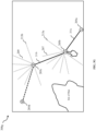
- FIG. 2C illustrates a user interface 200c displaying a first indicator data 207 and a second indicator data 209, not falling under the claimed invention.
- the waypoint 205b is the current waypoint and the waypoint 205c is the next waypoint.
- the first indicator data 207 i.e., a current indicator data
- the second indicator data 209 i.e., a next indicator data are displayed for the current waypoint 205b and the next waypoint 205c, respectively.
- the current indicator data 207 is a semicircular polar dot display.
- the orientation of the current indicator data 207 is determined by the positional relationship between the previous waypoint 205a and the current waypoint 205b. Further, the orientation corresponds to the direction of a line connecting the previous waypoint 205a and the current waypoint 205b.
- the next indicator data 209 is also a semicircular polar dot display, where the orientation of the next indicator data 209 is determined by the positional relationship between the current waypoint 205b and the next waypoint 205c. Further, the orientation of the next indicator data 209 coincides with the direction of a line connecting the current waypoint 205b and the next waypoint 205c.
- the current indicator data 207 indicates a distance from the current waypoint 205a. Further, the distance is displayed in a current waypoint area opposite the candidate position of the one or more of previously selected waypoints.
- the navigation planning device 101 is further configured to display the next indicator data 209 corresponding to the next waypoint 205c.
- the next indicator data 209 indicates a distance from the next waypoint 205c, and further the distance is displayed in a next waypoint area opposite the candidate position of the current waypoint 205b. Further, the current indicator data 207 and the next indicator data 209 are displayed simultaneously by the navigation planning device 101.
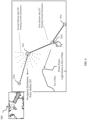
- FIG. 2D illustrates a user interface 200d displaying change in the orientation display associated with the first (current) indicator data 207 and in the orientation display associated with the second (next) indicator data 209 when the position of the current waypoint 205b is changed, in accordance with an example embodiment.
- the current waypoint 205b can be moved.
- the orientation of the first indicator data 207 i.e. the current indicator data
- the change in the orientation of the current indicator data 207 is based on the new positional relationship between the current waypoint 205b and the previous waypoint 205a.
- the orientation display of the next indicator data 209 is changed based on the new positional relationship between the current waypoint 205b and the next waypoint 205c.
- the dynamic change in the orientation of the current indicator data 207 and the next indicator data 209 enables the user 105 to easily set one or more navigation routes for the vessel in real time and consequently enables the user 105 to decide a better or the optimized navigation route.
- an intermediate navigation route is determined by connecting the waypoints 205a, 205b, and 205c, where the position of the waypoint 205b is modified to optimize the intermediate navigation route.
- the previous waypoint 205a is connected to the current waypoint 205b with a first extension line 211a and similarly, the current waypoint 205c is connected to the tentative next waypoint 205c with a second extension line 211b.
- the first extension line 211a and the second extension line 211b together forms the intermediate navigation route.
- a complete navigation route is determined by connecting the navigation start point 201 (for example, Liverpool, not shown in FIG. 2D ) to the navigation destination point 203 (for example, Harbor, not shown in FIG. 2D ) via the one or more waypoints (for example, 205a-205d) of the plurality of waypoints 205a-205e.
- the display of the indicator data may be selected from several types of display formats. Different formats of the indicators are illustrated in FIG. 3A-3G .
- FIG. 3A is described in conjunction with FIG. 2D .
- FIG. 3A illustrates an indicator display format with a plurality of dots arranged on one or more lines placed at predetermined intervals in predetermined directions, in accordance with an example embodiment.
- the predetermined intervals and directions maybe an angle indicating degree of separation between the plurality of dots.
- the degree of separation may be pre-determined or dynamically configured in real-time.
- the one or more lines pass through the corresponding waypoints. Further, one or more directions of the one or more lines are based on the orientation of the indicator data.
- the current indicator data 207 may be used by the current indicator data 207 to determine a distance from the current waypoint 205b to one or more next waypoints 205c-205e and the direction which comprises the candidate position of the one or more next waypoints 205c-205e.
- the indicator display format illustrated in FIG. 3A may be used to represent the next indicator data 209, where the next indicator data 209 may be used to determine a distance from a first point (for example, waypoint 205c) of the one or more next waypoints to a second point (for example, waypoint 205d or 205e) of the one or more next waypoints (205c-205e).Therefore, as illustrated in FIG.
- the first indicator data 207 includes the plurality of dots arranged on the first extension line 211a, where the first extension line 211a connects the previously selected one or more waypoints (for example, 205a) to the current waypoint (for example, 205b).
- the second indicator data 209 includes the plurality of dots arranged on the second extension line 211b, where the second extension line 211b connects the current waypoint (for example, 205b) to the one or more next waypoints (for example, 205c).
- the first indicator data 207 includes the plurality of dots arranged on a first line perpendicular to the first extension line 211a, and where the first line passes through the current waypoint (for example, 205b).
- the second indicator data 209 may include the plurality of dots arranged on a second line perpendicular to the second extension line 211b, and where the second line passes through the next waypoint (for example, 205c).
- FIG. 3B illustrates an indicator display format comprising plurality of dots arranged concentrically at predetermined intervals in one or more directions around a waypoint, in accordance with an example embodiment.
- the display format of FIG. 3B is similar to the display format of FIG.
- the display format of FIG. 3B may be used to determine more accurate distances from a waypoint as compared to the display format of FIG. 3A .
- FIG. 3C illustrates an indicator display format comprising concentric half circles at predetermined intervals in a predetermined direction around a waypoint, in accordance with an example embodiment.
- FIGs. 3D-3G illustrate indicator display formats comprising one or more lines with a scale showing a distance from the plurality of waypoints 205a-205e, where the one or more lines are placed at predetermined intervals in predetermined directions, and the one or more lines pass through the plurality of waypoints 205a-205e.
- FIG. 3D illustrates an indicator display format comprising a centre line 301 and an auxiliary line 303 perpendicular to the centre line 301, in accordance with an example embodiment. Each line is scaled to show distance from the centre, where the centre corresponds to one of the plurality of waypoints 205a-205e (either the current waypoint 205b or the one or more of the next waypoints 205c-205e).
- a distance from the current waypoint 205b to the one or more next waypoints may be determined based on the scale indicated on the one or more lines of the first indicator data 207, where the one or more lines pass through the current waypoint 205b.
- the second indicator data 209 is represented using the indicator display format of FIG.
- a distance from a first waypoint (for example, 205c) of the one or more next waypoints 205c-205e to a second waypoint (205d or 205e) of the one or more next waypoints (205c-205e) may be determined based on the scale indicated on the one or more lines of the second indicator data 209, where the one or more lines pass through the first point (for example, 205c) of the one or more next waypoints 205c-205e.
- FIG. 3E illustrates an indicator display format comprising auxiliary lines 305a and 305b separated by a degree of separation, where the degree of separation is 45° between the center line 301 and the auxiliary line 303 perpendicular to the centre line 301, in accordance with an example embodiment.
- selecting a candidate position for the next waypoint and the direction from the current waypoint 205b may be determined more accurately.
- FIG. 3F illustrates an indicator display format comprising plurality of auxiliary lines 307a and 307b between the auxiliary lines 305a and 305b having the degree of separation as 45° in multiple directions and the auxiliary line 303 perpendicular to the center line 301, in accordance with an example embodiment.
- a user interface where the indicator data format illustrated in FIG. 3F is used is described below with reference to FIG. 3G
- FIG. 3G illustrates a user interface 300g where the first indicator data 207 and the second indicator data 209 is represented using the plurality of auxiliary lines display format illustrated in FIG. 3F , in accordance with an example embodiment.
- the first indicator data 207 includes a first orthogonal auxiliary line 213a with a scale showing a distance from the current waypoint 205b to the one or more next waypoints 205c-205e, and where the first orthogonal auxiliary line 213a is perpendicular to the first extension line 211a, and passes through the current waypoint 205b.
- the second indicator data 209 includes a second orthogonal auxiliary line 213b with a scale showing a distance from a first point (for example, 205c) of the one or more next waypoints 205c-205e to a second point (for example, 205d) of the one or more next waypoints 205c-205e, and where the second orthogonal auxiliary line 213b is perpendicular to the second extension line 211b, and passes through the next waypoint (for example, 205c).
- the first extension line 211a comprises a scale showing a distance from the current waypoint 205b to the one or more next waypoints 205c-205e.
- the second extension line 211b comprises a scale showing a distance from a first point of the one or more next waypoints 205c-205e, to a second point of the one or more next waypoints.
- FIG. 4 illustrates a user interface 400 where the first indicator data 207 and the second indicator data 209 are represented with different shades, using different shade data.
- the second indicator data 209 is indicated with bold and dark black coloured plurality of dots around the next point 205c and the first indicator data 207 is indicated with light coloured plurality of dots. Representing the first indicator data 207 and the second indicator data 209 with different shades, enables the user 103 to easily distinguish between different indicator data.
- the first indicator data 207 and the second indicator data 209 may differ from each other in one or more of color data and luminance data. Further, as illustrated in FIG. 4 , a first orientation associated with display of the first indicator data 207 and a second orientation associated with display of the second indicator data 209 are determined by setting the first orientation and the second orientation to a predetermined point, respectively.
- the predetermined point may be the navigation destination point 203 (Belfast). Therefore, the first orientation and the second orientation may be set in a direction pointing towards the navigation destination point 203 shown in FIG. 2B .
- the predetermined point for the current waypoint 205b may correspond to other possible destinations (such as Isle of Man) from the current waypoint 205b and the predetermined point for the next waypoint 205c may correspond to the navigation destination point 203 (i.e. Southern), as illustrated in FIG. 4 .
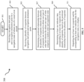
- FIG. 5 is a flowchart that illustrates steps of a navigation planning method 500 executed by the navigation planning device 101, in accordance with an example not falling under the claimed invention.
- the method 500 starts at step 501. Further, at step 503, the navigation start points 201 and a navigation destination point 203 may be received for a navigation route of a vessel or an aircraft.
- the navigation start point 201 and the navigation destination point 203 may be inputted by the user 105 through the display 129 and the inputted position data is received by the position specifying unit 117.
- the navigation start point 201 and the navigation destination point 203 may be specified by the user 103 by touching at specific locations or moving the cursor, or by inputting numerical data on the navigation map displayed on touch screen display panel of the display 129. Alternatively, the position data may also be inputted through the user device 103.
- a plurality of waypoints 205a-205e between the navigation start point 201 and the navigation destination point 203 may be received by the position specifying unit 117.
- the plurality of waypoints 205a-205e may correspond to candidate positions which may be changed or adjusted in real-time to determine an optimized navigation route.
- the plurality of waypoints 205a-205e may be selected randomly by the user 103. In another embodiment, the plurality of waypoints 205a-205e may be selected in a sequential order by the user 103.
- the plurality of waypoints 205a-205e may be specified by the user 103 by touching at specific locations, moving the cursor, or by inputting numerical data on the navigation route map (or the chart data) displayed on touch screen display panel of the display 129.
- the position data may also be inputted through the user device 103.
- the plurality of waypoints 205a-205e comprises one or more previously selected waypoints, a current waypoint, and one or more next way points.
- the navigation route may be determined by connecting the navigation start point 201 to the navigation destination point 203 through one or more waypoints of the plurality of waypoints 205a-205e.
- a positional relationship between the plurality of waypoints 205a-205e may be determined by the positional relation determination unit 119.
- the positional relationship may be determined based on position data of the plurality of waypoints 205a-205e, where the position data may comprise longitude and latitude information associated with each waypoint of the plurality of waypoints.
- the determined positional relationship between the one or more waypoints of the plurality of waypoints 205a-205e may be indicated on the navigation map, where the indicated positional relationship enables the user 105 to select the next waypoint to determine an optimized navigation route.
- At step 509, at least one indicator data corresponding to at least one waypoint of the plurality of waypoints205a-205e may be determined, based on the positional relationship between the plurality of waypoints 205a-205e.
- the indicator data comprises a first indicator data 207 (or a current indicator data) corresponding to the current waypoint, where the first indicator data 207 indicates a distance from the current waypoint. The distance from the current waypoint is displayed in a current waypoint area opposite the candidate position of the one or more of previously selected waypoints.
- the indicator data comprises a second indicator data 209 (or a next indicator data) corresponding to the next waypoint, where the second indicator data 209 indicates a distance from the next waypoint. The distance from the next waypoint is displayed in a next waypoint area opposite the candidate position of the current waypoint.
- the at least one waypoint and the corresponding at least one indicator data may be outputted or provided to the display 129 for displaying the at least one waypoint and the corresponding at least one indicator data associated with navigation route of the vessel or the aircraft.
- the user 105 may select one indicator display format of different indicator display format as illustrated in FIG. 3A to FIG. 3F .
- the indicator display format may be used to determine which one or more waypoints of the plurality of waypoints 205a-205e should be connected in order to determine the optimized navigation route.
- the optimized navigation route may be displayed on the display 129. Alternatively, the optimized navigation route may also be displayed on a screen of the user device 103.
- Example embodiments of the present invention may thus provide for the navigation planning device 101 and the navigation planning method that ensure accurate and easy selection of the one or more waypoints of the plurality of waypoints 205a-205e in order to determine the optimized navigation route for the vessel or for the aircraft.
Landscapes
- Engineering & Computer Science (AREA)
- Physics & Mathematics (AREA)
- General Physics & Mathematics (AREA)
- Aviation & Aerospace Engineering (AREA)
- Radar, Positioning & Navigation (AREA)
- Remote Sensing (AREA)
- General Engineering & Computer Science (AREA)
- Theoretical Computer Science (AREA)
- Automation & Control Theory (AREA)
- Human Computer Interaction (AREA)
- Navigation (AREA)
Claims (11)
- Navigationsplanungsvorrichtung (101), aufweisend:eine Positionsspezifizierungseinheit (117), die konfiguriert ist zum:Empfangen eines Navigationsstartpunkts (201) und eines Navigationszielpunkts (203) für eine Navigationsroute eines Schiffs oder eines Flugzeugs,Empfangen einer Vielzahl von Wegpunkten zwischen dem Navigationsstartpunkt (201) und dem Navigationszielpunkt (203);eine Einheit zur Bestimmung der Positionsbeziehungen (119), die konfiguriert ist zum:
Bestimmen einer Positionsbeziehung zwischen der Vielzahl von Wegpunkten (205a-205e), wobei die Vielzahl von Wegpunkten in einer zufälligen Reihenfolge oder einer sequentiellen Reihenfolge empfangen wird; undeine Indikatoranzeigeeinheit (121), die konfiguriert ist zum:Bestimmen von zwei Indikatorgrafiken, die an jeweiligen zwei Wegpunkten der Vielzahl von Wegpunkten (205a-205e) angezeigt werden sollen, basierend auf der Positionsbeziehung zwischen der Vielzahl von Wegpunkten (205a-205e); undAusgeben der zwei Wegpunkte und der jeweiligen Indikatorgrafiken an eine Anzeige, um sie auf einer Navigationskarte anzuzeigen,wobei die Vielzahl von Wegpunkten (205a-205e) einen ersten Wegpunkt (205a), einen zweiten Wegpunkt (205b) und einen dritten Wegpunkt (205c) aufweist,
wobei dem ersten Wegpunkt (205a) der zweite Wegpunkt (205b) folgt und dem zweiten Wegpunkt (205b) der dritte Wegpunkt (205c) auf der Navigationsroute zwischen dem Navigationsstartpunkt (201) und dem Navigationszielpunkt (203) folgt;wobei die zwei Indikatorgrafiken aufweisen:eine erste Indikatorgrafik (207), die an dem zweiten Wegpunkt (205b) angezeigt wird, wobei die erste Indikatorgrafik (207) eine Entfernung von dem zweiten Wegpunkt (205b) angibt, und wobei die Entfernung in einem zweiten Wegpunktbereich gegenüber der Position des ersten Wegpunkts (205a) angezeigt wird;eine zweite Indikatorgrafik (209), die an dem dritten Wegpunkt (205c) angezeigt wird, wobei die zweite Indikatorgrafik (209) eine Entfernung von dem dritten Wegpunkt (205c) angibt, und wobei die Entfernung in einem dritten Wegpunktbereich gegenüber der Position des zweiten Wegpunkts (205b) angezeigt wird;wobei die erste Indikatorgrafik (207) und die zweite Indikatorgrafik (209) gleichzeitig angezeigt werden,und wobeieine erste Ausrichtung, die mit der Anzeige der ersten Indikatorgrafik (207) assoziiert ist, basierend auf der Positionsbeziehung zwischen dem ersten Wegpunkt (205a) und dem zweiten Wegpunkt (205b) bestimmt wird;eine zweite Ausrichtung, die mit der Anzeige der zweiten Indikatorgrafik (209) assoziiert ist, basierend auf der Positionsbeziehung zwischen dem zweiten Wegpunkt (205b) und dem dritten Wegpunkt (205c) bestimmt wird; undwenn die Position des zweiten Wegpunkts (205b) bewegt wird, die erste Ausrichtung und die zweite Ausrichtung basierend auf der Bewegung der Position des zweiten Wegpunkts (205b) gleichzeitig geändert werden. - Navigationsplanungsvorrichtung (101) nach Anspruch 1,wobei die Positionsspezifizierungseinheit (117) konfiguriert ist zum Empfangen von Positionsdaten des Navigationsstartpunkts (201), des Navigationszielpunkts (203) und der Vielzahl von Wegpunkten (205a-205e), wobei die Positionsdaten durch mindestens eines von Folgendem empfangen werden: Berühren des Anzeigefelds, eines Cursors auf dem Anzeigefeld oder durch Eingeben numerischer Daten, undwobei die Navigationsplanungsvorrichtung (101) ferner eine Routeneinstelleinheit (125) aufweist, die konfiguriert ist zum Bestimmen der Navigationsroute durch Verbinden des Navigationsstartpunkts (201), eines oder mehrerer Wegpunkte der Vielzahl von Wegpunkten (205a-205e) und des Navigationszielpunkts (203).
- Navigationsplanungsvorrichtung (101) nach einem der Ansprüche 1-2,wobei die erste Indikatorgrafik (207) eine oder mehrere Linien mit einer Skala beinhaltet, die eine Entfernung von dem zweiten Wegpunkt zeigt, wobei die eine oder die mehreren Linien in vorbestimmten Intervallen in vorbestimmten Richtungen platziert sind, und wobei die eine oder die mehreren Linien durch den zweiten Wegpunkt verlaufen; undwobei die zweite Indikatorgrafik (209) ferner eine oder mehrere Linien mit einer Skala beinhaltet, die eine Entfernung von dem dritten Wegpunkt zeigt, wobei die eine oder die mehreren Linien in vorbestimmten Intervallen in vorbestimmten Richtungen platziert sind, und wobei die eine oder die mehreren Linien durch den dritten Wegpunkt verlaufen.
- Navigationsplanungsvorrichtung (101) nach einem der Ansprüche 1-2, wobei sich die erste Indikatorgrafik (207) und die zweite Indikatorgrafik (209) in einem oder mehreren von Farbdaten, Schattierungsdaten und Luminanzdaten zur Anzeige voneinander unterscheiden.
- Navigationsplanungsvorrichtung (101) nach einem der Ansprüche 1-2,wobei die erste Indikatorgrafik (207) eine Vielzahl von Punkten beinhaltet, die konzentrisch um den zweiten Wegpunkt in vorbestimmten Intervallen in einer oder mehreren Richtungen angeordnet sind, und wobei die eine oder die mehreren Richtungen auf der ersten Ausrichtung basieren, undwobei die zweite Indikatorgrafik (209) eine Vielzahl von Punkten beinhaltet, die konzentrisch um den dritten Wegpunkt in vorbestimmten Intervallen in einer oder mehreren Richtungen angeordnet sind, und wobei die eine oder die mehreren Richtungen auf der zweiten Ausrichtung basieren.
- Navigationsplanungsvorrichtung (101) nach einem der Ansprüche 1-2,wobei die erste Indikatorgrafik (207) eine Vielzahl von Punkten beinhaltet, die auf einer oder mehreren Linien angeordnet sind, die in vorbestimmten Intervallen in vorbestimmten Richtungen platziert sind, wobei die eine oder die mehreren Linien durch den zweiten Wegpunkt verlaufen, und wobei die eine oder die mehreren Richtungen auf der ersten Ausrichtung basieren; undwobei die zweite Indikatorgrafik (209) eine Vielzahl von Punkten beinhaltet, die auf einer oder mehreren Linien angeordnet sind, die in vorbestimmten Intervallen in vorbestimmten Richtungen platziert sind, wobei die eine oder die mehreren Linien durch den dritten Wegpunkt verlaufen, und wobei die eine oder die mehreren Richtungen auf der zweiten Ausrichtung basieren.
- Navigationsplanungsvorrichtung (101) nach einem der Ansprüche 1-2,wobei die erste Indikatorgrafik (207) die Vielzahl von Punkten beinhaltet, die auf einer ersten Verlängerungslinie angeordnet sind, die den ersten Wegpunkt und den zweiten Wegpunkt verbindet, undwobei die zweite Indikatorgrafik (209) die Vielzahl von Punkten beinhaltet, die auf einer zweiten Verlängerungslinie angeordnet sind, die den zweiten Wegpunkt und den dritten Wegpunkt verbindet.
- Navigationsplanungsvorrichtung (101) nach Anspruch 7,wobei die erste Indikatorgrafik (207) eine erste orthogonale Hilfslinie mit einer Skala beinhaltet, die eine Entfernung von dem zweiten Wegpunkt zeigt, und wobei die erste orthogonale Hilfslinie senkrecht zu der ersten Verlängerungslinie ist und durch den zweiten Wegpunkt verläuft; undwobei die zweite Indikatorgrafik (209) eine zweite orthogonale Hilfslinie mit einer Skala beinhaltet, die eine Entfernung von einem ersten Punkt des einen oder der mehreren nächsten Wegpunkte zu einem zweiten Punkt des einen oder der mehreren nächsten Wegpunkte zeigt, und wobei die zweite orthogonale Hilfslinie senkrecht zu der zweiten Verlängerungslinie ist und durch den dritten Wegpunkt verläuft;wobei die erste Verlängerungslinie eine Skala aufweist, die eine Entfernung von dem zweiten Wegpunkt zu dem einen oder den mehreren nächsten Wegpunkten zeigt; undwobei die zweite Verlängerungslinie eine Skala aufweist, die eine Entfernung von einem ersten Punkt des einen oder der mehreren nächsten Wegpunkte zu einem zweiten Punkt des einen oder der mehreren nächsten Wegpunkte zeigt,wobei die erste Indikatorgrafik (207) die Vielzahl von Punkten beinhaltet, die auf einer ersten Linie senkrecht zu der ersten Verlängerungslinie angeordnet sind, und wobei die erste Linie durch den zweiten Wegpunkt verläuft; undwobei die zweite Indikatorgrafik (209) die Vielzahl von Punkten beinhaltet, die auf einer zweiten Linie senkrecht zu der zweiten Verlängerungslinie angeordnet sind, und wobei die zweite Linie durch den dritten Wegpunkt verläuft.
- Navigationsplanungsvorrichtung (101) nach Anspruch 1, ferner aufweisend:einen Speicher (111), der konfiguriert ist zum Speichern von Kartendaten zur Navigation;eine Anzeige (129), die konfiguriert ist zum:Anzeigen mindestens eines Teils der Karte auf einem Anzeigefeld;Empfangen eines Navigationsstartpunkts (201) und eines Navigationszielpunkts (203) für eine Navigationsroute eines Schiffs oder eines Flugzeugs;Empfangen einer Vielzahl von Wegpunkten (205a-205e) zwischen dem Navigationsstartpunkt (201) und dem Navigationszielpunkt (203), wobei die Vielzahl von Wegpunkten (205a-205e) in einer zufälligen Reihenfolge oder einer sequentiellen Reihenfolge empfangen wird; undAnzeigen der zwei Wegpunkte und der jeweiligen Indikatorgrafiken auf der Navigationskarte.
- Navigationsplanungsverfahren (500), aufweisend:Empfangen (503) eines Navigationsstartpunkts (201) und eines Navigationszielpunkts (203) für eine Navigationsroute eines Schiffs oder eines Flugzeugs;Empfangen (505) einer Vielzahl von Wegpunkten (205a-205e) zwischen dem Navigationsstartpunkt (201) und dem Navigationszielpunkt (203);Bestimmen (507) einer Positionsbeziehung zwischen der Vielzahl von Wegpunkten (205a-205e), wobei die Vielzahl von Wegpunkten (205a-205e) in einer zufälligen Reihenfolge oder einer sequentiellen Reihenfolge empfangen wird;Bestimmen (509) von zwei Indikatorgrafiken, die an jeweiligen zwei Wegpunkten der Vielzahl von Wegpunkten (205a-205e) angezeigt werden sollen, basierend auf der Positionsbeziehung zwischen der Vielzahl von Wegpunkten (205a-205e); undAusgeben (511) der zwei Wegpunkte und der jeweiligen Indikatorgrafiken an eine Anzeige, um sie auf einer Navigationskarte anzuzeigen,wobei die Vielzahl von Wegpunkten (205a-205e) einen ersten Wegpunkt (205a), einen zweiten Wegpunkt (205b) und einen dritten Wegpunkt (205c) aufweist,
wobei dem ersten Wegpunkt (205a) der zweite Wegpunkt (205b) folgt und dem zweiten Wegpunkt (205b) der dritte Wegpunkt (205c) auf der Navigationsroute zwischen dem Navigationsstartpunkt (201) und dem Navigationszielpunkt (203) folgt;wobei die zwei Indikatorgrafiken aufweisen:eine erste Indikatorgrafik (207), die an dem zweiten Wegpunkt (205b) angezeigt wird, wobei die erste Indikatorgrafik (207) eine Entfernung von dem zweiten Wegpunkt (205b) angibt, und wobei die Entfernung in einem zweiten Wegpunktbereich gegenüber der Position des ersten Wegpunkts (205a) angezeigt wird;eine zweite Indikatorgrafik (209), die an dem dritten Wegpunkt (205c) angezeigt wird, wobei die zweite Indikatorgrafik (209) eine Entfernung von dem dritten Wegpunkt (205c) angibt, und wobei die Entfernung in einem dritten Wegpunktbereich gegenüber der Position des zweiten Wegpunkts (205b) angezeigt wird; undwobei die erste Indikatorgrafik (207) und die zweite Indikatorgrafik (209) gleichzeitig angezeigt werden,und wobeieine erste Ausrichtung, die mit der Anzeige der ersten Indikatorgrafik (207) assoziiert ist, basierend auf der Positionsbeziehung zwischen dem ersten Wegpunkt (205a) und dem zweiten Wegpunkt (205b) bestimmt wird;eine zweite Ausrichtung, die mit der Anzeige der zweiten Indikatorgrafik (209) assoziiert ist, basierend auf der Positionsbeziehung zwischen dem zweiten Wegpunkt (205b) und dem dritten Wegpunkt (205c) bestimmt wird; undwenn die Position des zweiten Wegpunkts (205b) bewegt wird, die erste Ausrichtung und die zweite Ausrichtung basierend auf der Bewegung der Position des zweiten Wegpunkts (205b) gleichzeitig geändert werden. - Nicht-transitorisches computerlesbares Medium, das Anweisungen speichert, die, wenn sie durch einen oder mehrere Prozessoren ausgeführt werden, eine Rechenvorrichtung veranlassen, ein Verfahren (500) durchzuführen, das aufweist:Empfangen eines Navigationsstartpunkts (201) und eines Navigationszielpunkts (203) für eine Navigationsroute eines Schiffs oder eines Flugzeugs;Empfangen einer Vielzahl von Wegpunkten (205a-205e) zwischen dem Navigationsstartpunkt (201) und dem Navigationszielpunkt (203);Bestimmen einer Positionsbeziehung zwischen der Vielzahl von Wegpunkten (205a-205e), wobei die Vielzahl von Wegpunkten (205a-205e) in einer zufälligen Reihenfolge oder einer sequentiellen Reihenfolge empfangen wird;Bestimmen von zwei Indikatorgrafiken, die an jeweiligen zwei Wegpunkten der Vielzahl von Wegpunkten (205a-205e) angezeigt werden sollen, basierend auf der Positionsbeziehung zwischen der Vielzahl von Wegpunkten (205a-205e); undAusgeben der zwei Wegpunkte und der jeweiligen Indikatorgrafiken an eine Anzeige, um sie auf einer Navigationskarte anzuzeigen,wobei die Vielzahl von Wegpunkten (205a-205e) einen ersten Wegpunkt (205a), einen zweiten Wegpunkt (205b) und einen dritten Wegpunkt (205c) aufweist,
wobei dem ersten Wegpunkt (205a) der zweite Wegpunkt (205b) folgt und dem zweiten Wegpunkt (205b) der dritte Wegpunkt (205c) auf der Navigationsroute zwischen dem Navigationsstartpunkt (201) und dem Navigationszielpunkt (203) folgt;wobei die zwei Indikatorgrafiken aufweisen:eine erste Indikatorgrafik (207), die an dem zweiten Wegpunkt (205b) angezeigt wird, wobei die erste Indikatorgrafik (207) eine Entfernung von dem zweiten Wegpunkt (205b) angibt, und wobei die Entfernung in einem zweiten Wegpunktbereich gegenüber der Position des ersten Wegpunkts (205a) angezeigt wird;eine zweite Indikatorgrafik (209), die an dem dritten Wegpunkt (205c) angezeigt wird, wobei die zweite Indikatorgrafik (209) eine Entfernung von dem dritten Wegpunkt (205c) angibt, und wobei die Entfernung in einem dritten Wegpunktbereich gegenüber der Position des zweiten Wegpunkts (205b) angezeigt wird; undwobei die erste Indikatorgrafik (207) und die zweite Indikatorgrafik (209) gleichzeitig angezeigt werden,und wobeieine erste Ausrichtung, die mit der Anzeige der ersten Indikatorgrafik (207) assoziiert ist, basierend auf der Positionsbeziehung zwischen dem ersten Wegpunkt (205a) und dem zweiten Wegpunkt (205b) bestimmt wird;eine zweite Ausrichtung, die mit der Anzeige der zweiten Indikatorgrafik (209) assoziiert ist, basierend auf der Positionsbeziehung zwischen dem zweiten Wegpunkt (205b) und dem dritten Wegpunkt (205c) bestimmt wird; undwenn die Position des zweiten Wegpunkts (205b) bewegt wird, die erste Ausrichtung und die zweite Ausrichtung basierend auf der Bewegung der Position des zweiten Wegpunkts (205b) gleichzeitig geändert werden.
Priority Applications (4)
| Application Number | Priority Date | Filing Date | Title |
|---|---|---|---|
| EP20212730.4A EP4012339B1 (de) | 2020-12-09 | 2020-12-09 | Vorrichtung und verfahren zur navigationsroutenplanung |
| JP2021090389A JP7654467B2 (ja) | 2020-12-09 | 2021-05-28 | 航路計画装置、航路計画システム、航路計画方法、及び航路計画支援をコンピュータに実行させるプログラム |
| US17/481,317 US11940280B2 (en) | 2020-12-09 | 2021-09-22 | Apparatus and method for navigation route planning |
| CN202111219234.1A CN114623828A (zh) | 2020-12-09 | 2021-10-20 | 航路计划装置、系统、方法以及存储介质 |
Applications Claiming Priority (1)
| Application Number | Priority Date | Filing Date | Title |
|---|---|---|---|
| EP20212730.4A EP4012339B1 (de) | 2020-12-09 | 2020-12-09 | Vorrichtung und verfahren zur navigationsroutenplanung |
Publications (2)
| Publication Number | Publication Date |
|---|---|
| EP4012339A1 EP4012339A1 (de) | 2022-06-15 |
| EP4012339B1 true EP4012339B1 (de) | 2025-04-30 |
Family
ID=73789913
Family Applications (1)
| Application Number | Title | Priority Date | Filing Date |
|---|---|---|---|
| EP20212730.4A Active EP4012339B1 (de) | 2020-12-09 | 2020-12-09 | Vorrichtung und verfahren zur navigationsroutenplanung |
Country Status (2)
| Country | Link |
|---|---|
| EP (1) | EP4012339B1 (de) |
| JP (1) | JP7654467B2 (de) |
Family Cites Families (2)
| Publication number | Priority date | Publication date | Assignee | Title |
|---|---|---|---|---|
| JP6812276B2 (ja) | 2017-03-13 | 2021-01-13 | 日本無線株式会社 | タッチパネルユニット |
| JP6762674B2 (ja) * | 2017-03-13 | 2020-09-30 | 日本無線株式会社 | 航海計画立案補助装置及び航海計画立案補助システム |
-
2020
- 2020-12-09 EP EP20212730.4A patent/EP4012339B1/de active Active
-
2021
- 2021-05-28 JP JP2021090389A patent/JP7654467B2/ja active Active
Also Published As
| Publication number | Publication date |
|---|---|
| JP7654467B2 (ja) | 2025-04-01 |
| EP4012339A1 (de) | 2022-06-15 |
| JP2022091667A (ja) | 2022-06-21 |
Similar Documents
| Publication | Publication Date | Title |
|---|---|---|
| US11940280B2 (en) | Apparatus and method for navigation route planning | |
| JP5766076B2 (ja) | 方向距離マーク使用地図表示装置 | |
| EP2792998B1 (de) | Systeme und Verfahren zur Erzeugung einer Navigationskarte | |
| EP4105602B1 (de) | Verfahren und vorrichtung zur navigationsplanung | |
| JPWO2016042932A1 (ja) | 自船周囲情報表示装置及び自船周囲情報表示方法 | |
| JP6762674B2 (ja) | 航海計画立案補助装置及び航海計画立案補助システム | |
| JP2016212646A (ja) | 船舶用表示装置 | |
| US20250052580A1 (en) | Positioning guidance method and system | |
| KR20180022922A (ko) | 맵 기반의 항법 방법, 장치 및 저장 매체 | |
| AU2017397651B2 (en) | Providing navigation directions | |
| US11112955B2 (en) | Nautical chart display device, nautical chart display method, and nautical chart display program | |
| JP7833338B2 (ja) | 航路編集支援装置及び航路編集支援方法 | |
| EP4012339B1 (de) | Vorrichtung und verfahren zur navigationsroutenplanung | |
| EP4105603B1 (de) | Verfahren und vorrichtung zur navigationsplanung | |
| JPWO2019065041A1 (ja) | 海図表示装置、海図表示方法、及び海図表示プログラム | |
| JP6872447B2 (ja) | 航海情報表示装置、航海情報表示方法、及び航海情報表示プログラム | |
| EP4105601A1 (de) | Verfahren und vorrichtung zur navigationsplanung | |
| JP2004294301A (ja) | 画面表示方法及びその方法をコンピュータにより実行させるためのプログラム | |
| JP2007309823A (ja) | 車載用ナビゲーション装置 | |
| JP4748778B2 (ja) | ナビゲーション装置 | |
| WO2015112106A1 (ru) | Электронная картографическая навигационная и информационная система | |
| JP2022023880A (ja) | 表示制御装置、表示制御方法、表示制御プログラム及び表示制御プログラムを記録したコンピュータ読み取り可能な記録媒体 | |
| JP2006039014A (ja) | ナビゲーション装置および山並み表示方法 | |
| JP2007025007A (ja) | 家形描画方法及び装置 | |
| JP2003035556A (ja) | 電子海図装置 |
Legal Events
| Date | Code | Title | Description |
|---|---|---|---|
| PUAI | Public reference made under article 153(3) epc to a published international application that has entered the european phase |
Free format text: ORIGINAL CODE: 0009012 |
|
| STAA | Information on the status of an ep patent application or granted ep patent |
Free format text: STATUS: THE APPLICATION HAS BEEN PUBLISHED |
|
| AK | Designated contracting states |
Kind code of ref document: A1 Designated state(s): AL AT BE BG CH CY CZ DE DK EE ES FI FR GB GR HR HU IE IS IT LI LT LU LV MC MK MT NL NO PL PT RO RS SE SI SK SM TR |
|
| STAA | Information on the status of an ep patent application or granted ep patent |
Free format text: STATUS: REQUEST FOR EXAMINATION WAS MADE |
|
| 17P | Request for examination filed |
Effective date: 20220906 |
|
| RBV | Designated contracting states (corrected) |
Designated state(s): AL AT BE BG CH CY CZ DE DK EE ES FI FR GB GR HR HU IE IS IT LI LT LU LV MC MK MT NL NO PL PT RO RS SE SI SK SM TR |
|
| STAA | Information on the status of an ep patent application or granted ep patent |
Free format text: STATUS: EXAMINATION IS IN PROGRESS |
|
| 17Q | First examination report despatched |
Effective date: 20231030 |
|
| GRAP | Despatch of communication of intention to grant a patent |
Free format text: ORIGINAL CODE: EPIDOSNIGR1 |
|
| STAA | Information on the status of an ep patent application or granted ep patent |
Free format text: STATUS: GRANT OF PATENT IS INTENDED |
|
| INTG | Intention to grant announced |
Effective date: 20241211 |
|
| RIN1 | Information on inventor provided before grant (corrected) |
Inventor name: MORITA, TAKATOSHI Inventor name: OKUDA, MASATO |
|
| GRAS | Grant fee paid |
Free format text: ORIGINAL CODE: EPIDOSNIGR3 |
|
| GRAA | (expected) grant |
Free format text: ORIGINAL CODE: 0009210 |
|
| STAA | Information on the status of an ep patent application or granted ep patent |
Free format text: STATUS: THE PATENT HAS BEEN GRANTED |
|
| AK | Designated contracting states |
Kind code of ref document: B1 Designated state(s): AL AT BE BG CH CY CZ DE DK EE ES FI FR GB GR HR HU IE IS IT LI LT LU LV MC MK MT NL NO PL PT RO RS SE SI SK SM TR |
|
| REG | Reference to a national code |
Ref country code: CH Ref legal event code: EP Ref country code: GB Ref legal event code: FG4D |
|
| REG | Reference to a national code |
Ref country code: DE Ref legal event code: R096 Ref document number: 602020050338 Country of ref document: DE |
|
| REG | Reference to a national code |
Ref country code: IE Ref legal event code: FG4D |
|
| REG | Reference to a national code |
Ref country code: NL Ref legal event code: MP Effective date: 20250430 |
|
| REG | Reference to a national code |
Ref country code: AT Ref legal event code: MK05 Ref document number: 1790382 Country of ref document: AT Kind code of ref document: T Effective date: 20250430 |
|
| PG25 | Lapsed in a contracting state [announced via postgrant information from national office to epo] |
Ref country code: FI Free format text: LAPSE BECAUSE OF FAILURE TO SUBMIT A TRANSLATION OF THE DESCRIPTION OR TO PAY THE FEE WITHIN THE PRESCRIBED TIME-LIMIT Effective date: 20250430 Ref country code: ES Free format text: LAPSE BECAUSE OF FAILURE TO SUBMIT A TRANSLATION OF THE DESCRIPTION OR TO PAY THE FEE WITHIN THE PRESCRIBED TIME-LIMIT Effective date: 20250430 Ref country code: PT Free format text: LAPSE BECAUSE OF FAILURE TO SUBMIT A TRANSLATION OF THE DESCRIPTION OR TO PAY THE FEE WITHIN THE PRESCRIBED TIME-LIMIT Effective date: 20250901 |
|
| REG | Reference to a national code |
Ref country code: LT Ref legal event code: MG9D |
|
| PG25 | Lapsed in a contracting state [announced via postgrant information from national office to epo] |
Ref country code: NO Free format text: LAPSE BECAUSE OF FAILURE TO SUBMIT A TRANSLATION OF THE DESCRIPTION OR TO PAY THE FEE WITHIN THE PRESCRIBED TIME-LIMIT Effective date: 20250730 Ref country code: GR Free format text: LAPSE BECAUSE OF FAILURE TO SUBMIT A TRANSLATION OF THE DESCRIPTION OR TO PAY THE FEE WITHIN THE PRESCRIBED TIME-LIMIT Effective date: 20250731 |
|
| PG25 | Lapsed in a contracting state [announced via postgrant information from national office to epo] |
Ref country code: PL Free format text: LAPSE BECAUSE OF FAILURE TO SUBMIT A TRANSLATION OF THE DESCRIPTION OR TO PAY THE FEE WITHIN THE PRESCRIBED TIME-LIMIT Effective date: 20250430 Ref country code: NL Free format text: LAPSE BECAUSE OF FAILURE TO SUBMIT A TRANSLATION OF THE DESCRIPTION OR TO PAY THE FEE WITHIN THE PRESCRIBED TIME-LIMIT Effective date: 20250430 |
|
| PG25 | Lapsed in a contracting state [announced via postgrant information from national office to epo] |
Ref country code: BG Free format text: LAPSE BECAUSE OF FAILURE TO SUBMIT A TRANSLATION OF THE DESCRIPTION OR TO PAY THE FEE WITHIN THE PRESCRIBED TIME-LIMIT Effective date: 20250430 |
|
| PG25 | Lapsed in a contracting state [announced via postgrant information from national office to epo] |
Ref country code: HR Free format text: LAPSE BECAUSE OF FAILURE TO SUBMIT A TRANSLATION OF THE DESCRIPTION OR TO PAY THE FEE WITHIN THE PRESCRIBED TIME-LIMIT Effective date: 20250430 |
|
| PG25 | Lapsed in a contracting state [announced via postgrant information from national office to epo] |
Ref country code: AT Free format text: LAPSE BECAUSE OF FAILURE TO SUBMIT A TRANSLATION OF THE DESCRIPTION OR TO PAY THE FEE WITHIN THE PRESCRIBED TIME-LIMIT Effective date: 20250430 |
|
| PG25 | Lapsed in a contracting state [announced via postgrant information from national office to epo] |
Ref country code: RS Free format text: LAPSE BECAUSE OF FAILURE TO SUBMIT A TRANSLATION OF THE DESCRIPTION OR TO PAY THE FEE WITHIN THE PRESCRIBED TIME-LIMIT Effective date: 20250731 |
|
| PG25 | Lapsed in a contracting state [announced via postgrant information from national office to epo] |
Ref country code: IS Free format text: LAPSE BECAUSE OF FAILURE TO SUBMIT A TRANSLATION OF THE DESCRIPTION OR TO PAY THE FEE WITHIN THE PRESCRIBED TIME-LIMIT Effective date: 20250830 |
|
| PG25 | Lapsed in a contracting state [announced via postgrant information from national office to epo] |
Ref country code: LV Free format text: LAPSE BECAUSE OF FAILURE TO SUBMIT A TRANSLATION OF THE DESCRIPTION OR TO PAY THE FEE WITHIN THE PRESCRIBED TIME-LIMIT Effective date: 20250430 |
|
| PGFP | Annual fee paid to national office [announced via postgrant information from national office to epo] |
Ref country code: DE Payment date: 20251028 Year of fee payment: 6 |
|
| PG25 | Lapsed in a contracting state [announced via postgrant information from national office to epo] |
Ref country code: DK Free format text: LAPSE BECAUSE OF FAILURE TO SUBMIT A TRANSLATION OF THE DESCRIPTION OR TO PAY THE FEE WITHIN THE PRESCRIBED TIME-LIMIT Effective date: 20250430 Ref country code: SM Free format text: LAPSE BECAUSE OF FAILURE TO SUBMIT A TRANSLATION OF THE DESCRIPTION OR TO PAY THE FEE WITHIN THE PRESCRIBED TIME-LIMIT Effective date: 20250430 |
|
| PG25 | Lapsed in a contracting state [announced via postgrant information from national office to epo] |
Ref country code: CZ Free format text: LAPSE BECAUSE OF FAILURE TO SUBMIT A TRANSLATION OF THE DESCRIPTION OR TO PAY THE FEE WITHIN THE PRESCRIBED TIME-LIMIT Effective date: 20250430 |
|
| PG25 | Lapsed in a contracting state [announced via postgrant information from national office to epo] |
Ref country code: EE Free format text: LAPSE BECAUSE OF FAILURE TO SUBMIT A TRANSLATION OF THE DESCRIPTION OR TO PAY THE FEE WITHIN THE PRESCRIBED TIME-LIMIT Effective date: 20250430 |
|
| PG25 | Lapsed in a contracting state [announced via postgrant information from national office to epo] |
Ref country code: SK Free format text: LAPSE BECAUSE OF FAILURE TO SUBMIT A TRANSLATION OF THE DESCRIPTION OR TO PAY THE FEE WITHIN THE PRESCRIBED TIME-LIMIT Effective date: 20250430 Ref country code: RO Free format text: LAPSE BECAUSE OF FAILURE TO SUBMIT A TRANSLATION OF THE DESCRIPTION OR TO PAY THE FEE WITHIN THE PRESCRIBED TIME-LIMIT Effective date: 20250430 |
|
| PG25 | Lapsed in a contracting state [announced via postgrant information from national office to epo] |
Ref country code: IT Free format text: LAPSE BECAUSE OF FAILURE TO SUBMIT A TRANSLATION OF THE DESCRIPTION OR TO PAY THE FEE WITHIN THE PRESCRIBED TIME-LIMIT Effective date: 20250430 |
|
| REG | Reference to a national code |
Ref country code: DE Ref legal event code: R097 Ref document number: 602020050338 Country of ref document: DE |
|
| PLBE | No opposition filed within time limit |
Free format text: ORIGINAL CODE: 0009261 |
|
| STAA | Information on the status of an ep patent application or granted ep patent |
Free format text: STATUS: NO OPPOSITION FILED WITHIN TIME LIMIT |
|
| REG | Reference to a national code |
Ref country code: CH Ref legal event code: L10 Free format text: ST27 STATUS EVENT CODE: U-0-0-L10-L00 (AS PROVIDED BY THE NATIONAL OFFICE) Effective date: 20260311 |
|
| 26N | No opposition filed |
Effective date: 20260202 |