EP4012277A1 - Chilling unit and air conditioning device - Google Patents
Chilling unit and air conditioning device Download PDFInfo
- Publication number
- EP4012277A1 EP4012277A1 EP19940671.1A EP19940671A EP4012277A1 EP 4012277 A1 EP4012277 A1 EP 4012277A1 EP 19940671 A EP19940671 A EP 19940671A EP 4012277 A1 EP4012277 A1 EP 4012277A1
- Authority
- EP
- European Patent Office
- Prior art keywords
- heat
- refrigerant
- machine chamber
- medium
- chilling unit
- Prior art date
- Legal status (The legal status is an assumption and is not a legal conclusion. Google has not performed a legal analysis and makes no representation as to the accuracy of the status listed.)
- Granted
Links
Images

Classifications
-
- F—MECHANICAL ENGINEERING; LIGHTING; HEATING; WEAPONS; BLASTING
- F24—HEATING; RANGES; VENTILATING
- F24F—AIR-CONDITIONING; AIR-HUMIDIFICATION; VENTILATION; USE OF AIR CURRENTS FOR SCREENING
- F24F1/00—Room units for air-conditioning, e.g. separate or self-contained units or units receiving primary air from a central station
- F24F1/06—Separate outdoor units, e.g. outdoor unit to be linked to a separate room comprising a compressor and a heat exchanger
- F24F1/20—Electric components for separate outdoor units
- F24F1/22—Arrangement or mounting thereof
-
- F—MECHANICAL ENGINEERING; LIGHTING; HEATING; WEAPONS; BLASTING
- F24—HEATING; RANGES; VENTILATING
- F24F—AIR-CONDITIONING; AIR-HUMIDIFICATION; VENTILATION; USE OF AIR CURRENTS FOR SCREENING
- F24F1/00—Room units for air-conditioning, e.g. separate or self-contained units or units receiving primary air from a central station
- F24F1/06—Separate outdoor units, e.g. outdoor unit to be linked to a separate room comprising a compressor and a heat exchanger
- F24F1/46—Component arrangements in separate outdoor units
-
- F—MECHANICAL ENGINEERING; LIGHTING; HEATING; WEAPONS; BLASTING
- F24—HEATING; RANGES; VENTILATING
- F24F—AIR-CONDITIONING; AIR-HUMIDIFICATION; VENTILATION; USE OF AIR CURRENTS FOR SCREENING
- F24F1/00—Room units for air-conditioning, e.g. separate or self-contained units or units receiving primary air from a central station
- F24F1/06—Separate outdoor units, e.g. outdoor unit to be linked to a separate room comprising a compressor and a heat exchanger
- F24F1/46—Component arrangements in separate outdoor units
- F24F1/48—Component arrangements in separate outdoor units characterised by air airflow, e.g. inlet or outlet airflow
- F24F1/50—Component arrangements in separate outdoor units characterised by air airflow, e.g. inlet or outlet airflow with outlet air in upward direction
-
- F—MECHANICAL ENGINEERING; LIGHTING; HEATING; WEAPONS; BLASTING
- F25—REFRIGERATION OR COOLING; COMBINED HEATING AND REFRIGERATION SYSTEMS; HEAT PUMP SYSTEMS; MANUFACTURE OR STORAGE OF ICE; LIQUEFACTION SOLIDIFICATION OF GASES
- F25B—REFRIGERATION MACHINES, PLANTS OR SYSTEMS; COMBINED HEATING AND REFRIGERATION SYSTEMS; HEAT PUMP SYSTEMS
- F25B13/00—Compression machines, plants or systems, with reversible cycle
-
- F—MECHANICAL ENGINEERING; LIGHTING; HEATING; WEAPONS; BLASTING
- F25—REFRIGERATION OR COOLING; COMBINED HEATING AND REFRIGERATION SYSTEMS; HEAT PUMP SYSTEMS; MANUFACTURE OR STORAGE OF ICE; LIQUEFACTION SOLIDIFICATION OF GASES
- F25B—REFRIGERATION MACHINES, PLANTS OR SYSTEMS; COMBINED HEATING AND REFRIGERATION SYSTEMS; HEAT PUMP SYSTEMS
- F25B2313/00—Compression machines, plants or systems with reversible cycle not otherwise provided for
- F25B2313/003—Indoor unit with water as a heat sink or heat source
-
- F—MECHANICAL ENGINEERING; LIGHTING; HEATING; WEAPONS; BLASTING
- F25—REFRIGERATION OR COOLING; COMBINED HEATING AND REFRIGERATION SYSTEMS; HEAT PUMP SYSTEMS; MANUFACTURE OR STORAGE OF ICE; LIQUEFACTION SOLIDIFICATION OF GASES
- F25B—REFRIGERATION MACHINES, PLANTS OR SYSTEMS; COMBINED HEATING AND REFRIGERATION SYSTEMS; HEAT PUMP SYSTEMS
- F25B2400/00—Component parts or details not otherwise provided for in this subclass
- F25B2400/06—Several compression cycles arranged in parallel
-
- F—MECHANICAL ENGINEERING; LIGHTING; HEATING; WEAPONS; BLASTING
- F25—REFRIGERATION OR COOLING; COMBINED HEATING AND REFRIGERATION SYSTEMS; HEAT PUMP SYSTEMS; MANUFACTURE OR STORAGE OF ICE; LIQUEFACTION SOLIDIFICATION OF GASES
- F25B—REFRIGERATION MACHINES, PLANTS OR SYSTEMS; COMBINED HEATING AND REFRIGERATION SYSTEMS; HEAT PUMP SYSTEMS
- F25B2400/00—Component parts or details not otherwise provided for in this subclass
- F25B2400/07—Details of compressors or related parts
- F25B2400/075—Details of compressors or related parts with parallel compressors
Definitions
- the present disclosure relates to a chilling unit and an air-conditioning apparatus.
- the present disclosure particularly relates to a layout of devices and other components to be installed in a housing of the chilling unit.
- a system including a chilling unit serving as a heat source unit, and a load unit.
- a heat-medium circulation circuit through which a heat medium including water or brine is circulated is formed between the chilling unit and the load unit to perform air-conditioning and other control.
- the chilling unit heats or cools the heat medium to supply heat to the load unit.
- the load unit provides heat supplied via the heat medium to a heat load.
- a load unit performs air-conditioning by heating or cooling air in the room.
- chilling unit in which devices forming each of a plurality of independent refrigerant circuits are installed (see, for example, Patent Literature 1).
- control-system devices are also installed, such as a control board and a power module.
- the control board includes a controller to control the constituent devices of the refrigerant circuit, such as a compressor and an air-sending device.
- the power module constitutes an inverter device or other device.
- control-system devices are accommodated in a control box.
- a plurality of control boxes may be installed corresponding to the refrigerant circuits to be controlled.
- Patent Literature 1 Japanese Patent Publication No. 5401563
- a worker may sometimes perform maintenance work on control-system devices, such as adjusting settings on the constituent devices of the refrigerant circuit or repairing problems.
- control-system devices such as adjusting settings on the constituent devices of the refrigerant circuit or repairing problems.
- the worker needs to gain access to the control boxes from multiple sides of the chilling unit by moving from one side to the other side during the maintenance work. This results in degradation in work efficiency, and impairs ease of work.
- chilling units There may be some cases where a plurality of chilling units are arranged in parallel to each other. At this time, if a plurality of control boxes are located on opposite sides of each of the chilling units, workers may perform maintenance work on the chilling units in workspaces overlapping one another. When the chilling units are arranged with a narrow spacing between them, it is difficult to ensure an adequate workspace for each of the workers. There may be a possibility that ease of work is impaired.
- the present disclosure has been achieved to solve the above problems, and it is an object of the present disclosure to provide a chilling unit that can improve ease of work, and provide an air-conditioning apparatus.
- a chilling unit includes a machine chamber being a housing with a rectangular bottom and accommodating therein devices forming each of a plurality of systems of refrigerant circuits, a plurality of heat-medium heat exchangers, each being configured to exchange heat between refrigerant and a heat medium serving as a heat delivering medium through the plurality of systems of refrigerant circuits, and each being configured to serve as a part of the devices forming the refrigerant circuits, and a plurality of refrigerant circuit-side control boxes, each including an electric device configured to drive and control the devices forming the refrigerant circuits, wherein the plurality of refrigerant circuit-side control boxes are located next to each other in the machine chamber in a longitudinal direction thereof alongside one of longitudinal sides of the machine chamber.
- An air-conditioning apparatus forms a heat-medium circulation circuit through which a heat medium is circulated by connecting the chilling unit described above and an indoor unit by pipes, the indoor unit including an indoor heat exchanger and a flow-rate adjustment device, the indoor heat exchanger being configured to exchange heat between the heat medium and indoor air to be air-conditioned, the flow-rate adjustment device being installed corresponding to the indoor heat exchanger and configured to adjust a flow rate of the heat medium passing through the indoor heat exchanger.
- the chilling unit is of a configuration in which the plurality of refrigerant circuit-side control boxes are located next to each other in a longitudinal direction of the machine chamber alongside only one of the longitudinal sides thereof. This configuration allows a worker to work on the refrigerant circuit-side control boxes on one side of the machine chamber without moving to the other side during the work.
- Fig. 1 illustrates the external appearance of a chilling unit according to Embodiment 1.
- a chilling unit 100 is described as a typical heat source unit to supply heat to indoor units 200 serving as a load-side device which will be described later.
- a heat medium that delivers heat supplied from the chilling unit 100 and provides the heat to the indoor units 200 is assumed to be water.
- the heat medium is not limited to water, but may be brine or other fluids.
- the chilling unit 100 includes a machine chamber 1, air heat exchangers 2, and outdoor fans 3.
- the machine chamber 1 is a housing in which devices forming the refrigerant circuit, and other devices are accommodated. Since the machine chamber 1 is provided at the lower portion of the chilling unit 100 to serve as a base portion supporting the chilling unit 100, the machine chamber 1 is the housing with a rectangular bottom.
- the machine chamber 1 in Embodiment 1 is the housing in the shape of a cuboid box. In the machine chamber 1, the direction extending along the longer side of the housing is defined as a longitudinal direction, while the direction extending along the shorter side of the housing is defined as a shorter-side direction. A direction perpendicular to the longitudinal direction and the shorter-side direction is defined as a height direction. The machine chamber 1 will be described later.
- Each of the air heat exchangers 2 is one of the devices forming the refrigerant circuit.
- the air heat exchangers 2 are fin-and-tube heat exchangers to exchange heat between refrigerant and outdoor air.
- the chilling unit 100 in Embodiment 1 includes a plurality of systems of refrigerant circuits, that is, in this case, four systems of refrigerant circuits. Due to this configuration, in the chilling unit 100 in Embodiment 1, four air heat exchangers 2A to 2D are installed on the top of the machine chamber 1.
- the air heat exchanger 2A and the air heat exchanger 2B are paired together, while the air heat exchanger 2C and the air heat exchanger 2D are paired together.
- a pair of air heat exchangers 2 is located facing each other with the spacing between the air heat exchangers 2 being increased toward the top side, such that the pair of air heat exchangers 2 forms a V-shape when the chilling unit 100 is viewed from the shorter-side of the machine chamber 1 as illustrated by the arrow A.
- two pairs of air heat exchangers 2 are located next to each other along the longitudinal direction of the machine chamber 1.
- the outdoor fans 3 are propeller fans to cause the outdoor air to pass through the air heat exchangers 2.
- the outdoor fans 3 are located on the top side of the pair of air heat exchangers 2 at a position in the V-shape formed between the pair of air heat exchangers 2.
- the chilling unit 100 in Embodiment 1 includes four outdoor fans 3A to 3D.
- Fig. 2 illustrates the configuration of an air-conditioning apparatus, centering on the chilling unit according to Embodiment 1.
- the chilling unit 100 in Embodiment 1 includes four systems of refrigerant circuits. Two of the four systems of refrigerant circuits are grouped together to share a single unit of water heat exchanger 60.
- the chilling unit 100 has two groups, each including two systems of refrigerant circuits. In a heat-medium circulation circuit, two units of water heat exchangers 60 are connected in series by pipes to cool or heat water that is a heat medium in two stages.
- a compressor 30, a four-way valve 50, the air heat exchanger 2, an expansion valve 70, the water heat exchanger 60, and an accumulator 40 are connected by pipes respectively to form the refrigerant circuit.
- the refrigerant to be used include a single refrigerant such as R-22 and R-134a, a near-azeotropic refrigerant mixture such as R-410A and R-404A, and a non-azeotropic refrigerant mixture such as R-407C.
- Compressors 30 compress suctioned refrigerant and discharge the compressed refrigerant.
- Each of the compressors 30 is driven through a compressor inverter drive device (not illustrated) and other devices.
- Each of the compressors 30 optionally changes the driving frequency on the basis of an instruction from a refrigerant circuit-side control device (not illustrated), and can thereby change the capacity of the compressor 30, which is the amount of refrigerant to be delivered per unit time.
- the inverter drive device and the refrigerant circuit-side control device are control-system devices accommodated in a refrigerant circuit-side control box 10 which will be described later.
- Four-way valves 50 serve as a flow-passage switching device, and switch between flow directions of refrigerant depending on the mode of operation to be performed, on the basis of an instruction from the refrigerant circuit-side control device described above.
- each of the four-way valves 50 allows high-temperature high-pressure refrigerant discharged from the compressor 30 to flow into the air heat exchanger 2.
- each of the four-way valves 50 allows high-temperature high-pressure refrigerant discharged from the compressor 30 to flow into the water heat exchanger 60.
- the air heat exchangers 2 exchange heat between refrigerant and the outside air as described above.
- each of the air heat exchangers 2 functions as an evaporator, and exchanges heat between air and low-pressure refrigerant having flowed into the air heat exchanger 2 through the expansion valve 70 to evaporate and vaporize the refrigerant.
- each of the air heat exchangers 2 functions as a condenser, and exchanges heat between air and low-pressure refrigerant having flowed into the air heat exchanger 2 through the compressor 30 to condense and liquefy the refrigerant.
- the outdoor fans 3 (outdoor fans 3A to 3D) deliver air to the air heat exchangers 2 to help heat exchange between the refrigerant and the air, as described above.
- the outdoor fans 3 are driven through a fan inverter drive device (not illustrated) and other devices.
- Each of the outdoor fans 3 optionally changes the driving frequency on the basis of an instruction from the refrigerant circuit-side control device described above, and can thereby change the airflow amount.
- the air heat exchanger 2 and the outdoor fan 3 are brought into one-to-one correspondence, but are not particularly limited to this configuration.
- the water heat exchangers 60 serve as a heat-medium heat exchanger, and exchange heat between refrigerant and water that is a heat medium.
- Each of the water heat exchangers 60 serves as a flow passage of the two systems of refrigerant circuits, and also serves as a flow passage of the heat-medium circulation circuit. Therefore, the water heat exchanger 60 is a device forming the refrigerant circuit, while being a device forming the heat-medium circulation circuit.
- the water heat exchanger 60 functions as a condenser during heating operation, and exchanges heat between water and refrigerant having flowed into the water heat exchanger 60 through the compressor 30 to condense and liquefy the refrigerant, or to condense the refrigerant to be brought into a two-phase gas-liquid state, thereby heating the water.
- the water heat exchanger 60 functions as an evaporator during cooling operation, and exchanges heat between water and refrigerant having flowed into the water heat exchanger 60 through the expansion valve 70 to evaporate and vaporize the refrigerant, thereby cooling the water.
- Expansion valves 70 serve as an expansion device and, for example, change the opening degree to adjust the pressure and other conditions of refrigerant passing through the water heat exchangers 60.
- Each of the expansion valves 70 in Embodiment 1 is made up of an electronic expansion valve that can change the opening degree on the basis of an instruction from the refrigerant circuit-side control device described above.
- the expansion valve 70 is not limited to being made up of this electronic expansion valve.
- the expansion valve 70 may also be a thermostatic expansion valve that can change the opening degree on the basis of the temperature of refrigerant.
- Accumulators 40 are provided on the suction side of the compressors 30 to accumulate therein extra refrigerant for the refrigerant circuit.
- the pump 80 is one of the devices forming the heat-medium circulation circuit.
- the pump 80 draws water and applies a pressure to the water to be delivered and circulated through the heat-medium circulation circuit.
- a pump inverter drive device (not illustrated) optionally changes the driving frequency on the basis of an instruction from a pump-side control device (not illustrated), and can thereby change the capacity of the pump 80.
- the pump inverter drive device and the pump-side control device are control-system devices accommodated in a pump control box 90 which will be described later.
- the indoor units 200 deliver conditioned air to a room space to be air-conditioned.
- the indoor units 200 (indoor units 200A and 200B) in Embodiment 1 illustrated in Fig. 2 include indoor heat exchangers 201 (indoor heat exchangers 201A and 201B), indoor flow-rate adjustment devices 202 (indoor flow-rate adjustment devices 202A and 202B), and indoor fans 203 (indoor fans 203A and 203B).
- the indoor heat exchangers 201 and the indoor flow-rate adjustment devices 202 are the devices forming the heat-medium circulation circuit.
- Fig. 2 illustrates the air-conditioning apparatus including two units of indoor units 200, however, the number of indoor units 200 is not particularly limited.
- Each of the indoor flow-rate adjustment devices 202 is made up of, for example, a two-way valve that can control the opening degree (opening area) of the valve, and other elements.
- the indoor flow-rate adjustment device 202 controls the flow rate of water flowing into/out of the indoor heat exchanger 201 by adjusting the opening degree of the valve.
- the indoor flow-rate adjustment device 202 adjusts the amount of water passing through the indoor heat exchanger 201, such that the indoor heat exchanger 201 can exchange heat by the amount of heat according to a heat load in the room.
- the indoor flow-rate adjustment device 202 can fully close the valve to stop water supply to prevent the water from flowing into/out of the indoor heat exchanger 201.
- the indoor flow-rate adjustment device 202 is installed on a pipe through which water flows out of the indoor heat exchanger 201.
- the installation of the indoor flow-rate adjustment device 202 is not limited to this location.
- the indoor flow-rate adjustment device 202 may be installed on a pipe through which water flows into the indoor heat exchanger 201.
- the indoor heat exchanger 201 exchanges heat between water and the indoor air in the room space supplied from the indoor fan 203.
- the indoor fan 203 causes the air in the room space to pass through the indoor heat exchanger 201, thereby generating a flow of air returning to the room space.
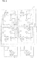
- Fig. 3 is an explanatory diagram describing the device layout in the machine chamber of the chilling unit according to Embodiment 1.
- Fig. 3 illustrates the interior of the machine chamber 1 when the interior of the machine chamber 1 is viewed from the top side.
- the machine chamber 1 of the chilling unit 100 in Embodiment 1 includes the devices forming the refrigerant circuit, the devices forming the heat-medium circulation circuit, and the control-system devices configured to control these devices.
- Fig. 3 illustrates four compressors 30 (compressors 30A to 30D), four accumulators 40 (accumulators 40A to 40D), and four four-way valves 50 (four-way valves 50A to 50D).
- Fig. 3 also illustrates two water heat exchangers 60 (water heat exchangers 60A and 60B).
- the machine chamber 1 further includes four expansion valves 70 (expansion valves 70A to 70D) although the four expansion valves 70 are not illustrated in Fig. 3 .
- the machine chamber 1 includes the pump 80 that is the device forming the heat-medium circulation circuit through which water that is a heat medium is circulated.
- the machine chamber 1 further includes two refrigerant circuit-side control boxes 10 (refrigerant circuit-side control boxes 10A and 10B), in each of which the control-system devices and other devices are accommodated.
- the machine chamber 1 still further includes the pump control box 90 and a power-supply terminal box 20.
- the power-supply terminal box 20 is located nearest the arrow A-side illustrated in Figs. 1 and 3 .
- a plurality of refrigerant circuit-side control boxes 10 are located next to each other in the longitudinal direction of the machine chamber 1.
- the refrigerant circuit-side control boxes 10 will be described later.
- the devices forming the refrigerant circuit are located on the other longitudinal side of the machine chamber 1 opposite to the side on which the plurality of refrigerant circuit-side control boxes 10 are located.
- the compressor 30, the accumulator 40, the four-way valve 50, and the expansion valve 70 are arranged collectively for each system of refrigerant circuit, and the systems of refrigerant circuits are located next to one another along the longitudinal direction.
- the compressors 30 and the accumulators 40 both have a relatively large volume, and thus are located next to each other along the other longitudinal side of the machine chamber 1. Therefore, the compressors 30 and the accumulators 40 are located in parallel to the plurality of refrigerant circuit-side control boxes 10 in the short-side direction of the machine chamber 1.
- a plurality of water heat exchangers 60 are located, that are the devices forming the refrigerant circuit, while being the devices forming the heat-medium circulation circuit.
- the pump 80 and the pump control box 90 both of which form the heat-medium circulation circuit, are located at a position furthest from the arrow A-side. Therefore, the devices of the refrigerant circuit, and the devices of the heat-medium circulation circuit are located separately from each other with the water heat exchangers 60 serving as the boundary between these devices.
- a power-supply terminal (not illustrated) is accommodated.
- the electric devices such as an inverter device including a power module to drive the devices, and a control board including a controller, are supplied with power through the power-supply terminal connected to the outside wire.
- the electric devices such as an inverter device including a power module to drive the devices, and a control board including a controller, are supplied with power through the power-supply terminal connected to the outside wire.
- respective machine chambers 1 of the chilling units 100 are located with their longitudinal sides facing each other. Therefore, if a power-supply terminal is provided somewhere on the longitudinal side of the chilling unit 100, it is difficult to connect the outside wire to the power-supply terminal.
- the power-supply terminal box 20 is accommodated in the machine chamber 1 at one end portion thereof located nearest the arrow A-side, such that the power-supply terminal can be seen from the short side of the machine chamber 1, and thus the outside wire can be easily connected to the power-supply terminal.
- the pump 80 is accommodated in the machine chamber 1 at another end portion thereof located furthest from the arrow A-side on the other side of the end portion in which the power-supply terminal box 20 is accommodated.
- the pump 80 is one of the devices forming the heat-medium circulation circuit.
- the plurality of water heat exchangers 60 are located, which are the devices forming the refrigerant circuit, and also forming the heat-medium circulation circuit.
- the pump 80 and the plurality of water heat exchangers 60 accommodated in the machine chamber 1 of the chilling unit 100 need to be connected by pipes to another device including the devices forming the heat-medium circulation circuit.
- the pump 80 is accommodated in the machine chamber 1 at another end portion thereof located furthest from the arrow A-side, such that heat-medium pipes connected to the pump 80 and the plurality of water heat exchangers 60 can be seen from the shorter-side face of the machine chamber 1, and thus the another device is easily connected to the heat-medium pipes.
- the pump control box 90 is located at a position adjacent to the pump 80 on the longitudinal side of the machine chamber 1, that is, on the same side on which the plurality of refrigerant circuit-side control boxes 10 are located. Therefore, a worker can perform maintenance of the electric devices in the pump control box 90 without the need for moving to the other longitudinal side.
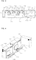
- Fig. 4 is an explanatory diagram describing the layout relationship between the power-supply terminal box and each refrigerant circuit-side control box in the machine chamber according to Embodiment 1.
- the chilling unit 100 in Embodiment 1 has two refrigerant circuit-side control boxes 10A and 10B accommodated in the machine chamber 1.
- a power supply line 21 extending from the power-supply terminal box 20 is connected to each refrigerant circuit-side control box 10.
- the plurality of refrigerant circuit-side control boxes 10 are located next to each other in the longitudinal direction of the machine chamber 1 alongside one of the longitudinal sides of the machine chamber 1.
- the plurality of refrigerant circuit-side control boxes 10 are located next to each other alongside one of the longitudinal sides of the machine chamber 1, so that a worker can work on the plurality of refrigerant circuit-side control boxes 10 in a workspace on one of the longitudinal sides of the machine chamber 1. This eliminates the need for a worker to work in separated spaces on opposite longitudinal sides.
- the worker can perform maintenance and other work on the plurality of refrigerant circuit-side control boxes 10 in a workspace on one of the longitudinal sides without moving to the other longitudinal side. Even in a case where a plurality of chilling units 100 are installed next to one another in the shorter-side direction, the workspaces for the chilling units 100 do not overlap one another. This allows a plurality of workers to smoothly perform maintenance and other work on the plurality of chilling units 100.
- Each of the refrigerant circuit-side control boxes 10 includes a compression-board heat sink 11 (compression-board heat sinks 11A and 11B) and a fan-board heat sink 12 (fan-board heat sinks 12A and 12B).
- Each of the refrigerant circuit-side control boxes 10 further includes a heat-sink cooling fan 13 (heat-sink cooling fans 13A and 13B).
- the compression-board heat sink 11, the fan-board heat sink 12, and the heat-sink cooling fan 13 are installed on the outside of the refrigerant circuit-side control box 10.
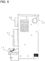
- Fig. 5 is an explanatory diagram describing the configuration of the refrigerant circuit-side control box according to Embodiment 1.
- Fig. 5 illustrates the refrigerant circuit-side control box 10 viewed from the side.
- the compression-board heat sink 11 is in contact with a power module included in the compressor inverter drive device configured to drive the compressor 30 and accommodated in the refrigerant circuit-side control box 10 to transfer heat generated by the power module driving the devices.
- the fan-board heat sink 12 is in contact with a power module included in the fan inverter drive device configured to drive the outdoor fans 3 and accommodated in the refrigerant circuit-side control box 10 to transfer heat generated by the power module driving the devices.
- Fig. 5 illustrates the refrigerant circuit-side control box 10 viewed from the side.
- the compression-board heat sink 11 is in contact with a power module included in the compressor inverter drive device configured to drive the compressor 30 and accommodated in the refrigerant circuit-side control box 10 to transfer heat generated by the
- the heat-sink cooling fan 13 delivers air to the compression-board heat sink 11 and the fan-board heat sink 12 from below them to help transfer heat from the compression-board heat sink 11 and the fan-board heat sink 12.
- the heat-sink cooling fan 13 forms a flow of air that flows from the lower portion of the heat sinks toward the upper portion thereof, so that heat can be efficiently transferred from the heat sinks.
- a plurality of refrigerant circuit-side control boxes 10 of the same configuration are located next to each other along the longitudinal direction.
- this allows the compression-board heat sink 11A and the fan-board heat sink 12A to be located separately from the compression-board heat sink 11B and the fan-board heat sink 12B in the machine chamber 1, instead of the compression-board heat sink 11A and the fan-board heat sink 12A being located in proximity to the compression-board heat sink 11B and the fan-board heat sink 12B. Therefore, this can prevent the temperature from increasing in a particular area of the machine chamber 1, and can reduce variations in the temperature in the machine chamber 1.
- the chilling unit 100 in Embodiment 1 is of a configuration in which a plurality of refrigerant circuit-side control boxes 10 are located next to each other in the longitudinal direction of the machine chamber 1 alongside one of the longitudinal sides of the machine chamber 1.
- the plurality of refrigerant circuit-side control boxes 10 are arranged alongside only one side of the machine chamber 1, so that a worker can perform maintenance and other work on the plurality of refrigerant circuit-side control boxes 10 on one side of the machine chamber 1 without moving to the other side.
- the workspaces for the chilling units 100 do not overlap one another, so that workers can perform maintenance work on the chilling units 100 without interfering with each other.
- the plurality of refrigerant circuit-side control boxes 10 are located next to each other along the longitudinal direction of the machine chamber 1, and this can ensure an adequate workspace for workers. Furthermore, the plurality of refrigerant circuit-side control boxes 10 are located next to each other along the longitudinal direction of the machine chamber 1, and this allows the compression-board heat sink 11 and the fan-board heat sink 12 in each of the refrigerant circuit-side control boxes 10 to be located separately from those in another refrigerant circuit-side control box 10. This can reduce variations in the temperature in the machine chamber 1.
- the machine chamber 1 has been explained as being a housing in the shape of a cuboid box with a rectangular bottom.
- the machine chamber 1 is not limited to being this housing.
- the machine chamber 1 may be a housing in the shape of a box with a trapezoidal cross section when viewed from the short side, or may be a housing in the shape of truncated square pyramid.
- the chilling unit 100 of a commonly-called “dual configuration” has been explained, in which two systems of refrigerant circuits are grouped together to share a single unit of water heat exchanger 60.
- the configuration of the chilling unit 100 is not limited thereto.
- the chilling unit 100 may be of a commonly-called “single configuration" in which refrigerant is circulated through a single system of refrigerant circuit such that a single unit of water heat exchanger 60 exchanges heat between the refrigerant and a heat medium.
- the heat-sink cooling fan 13 is driven to deliver air to cool the compression-board heat sink 11 and the fan-board heat sink 12.
- the chilling unit 100 is not limited to this cooling method.
- the refrigerant circuit-side control boxes 10 are located on one of the longitudinal sides, while the devices forming the refrigerant circuit are located on the other longitudinal side, as described above.
- the compression-board heat sink 11 and the fan-board heat sink 12 may be in direct contact with a refrigerant pipe on the suction side of the compressor 30, through which low-temperature refrigerant passes, in the refrigerant circuit, or may be in contact with the refrigerant pipe through a medium, to transfer heat.
- the compression-board heat sink 11 and the fan-board heat sink 12 may be in direct contact with the accumulator 40, or in contact with the accumulator 40 through a medium.
- a contact of the heat sinks with the refrigerant pipe or other device can be employed in combination with the heat-sink cooling fan 13. For example, when the heat sinks are brought into contact with the refrigerant pipe through a medium, grease or other material is applied or a plate is attached to the refrigerant pipe to increase the contact area.
- the chilling unit 100 in Embodiment 1 described above is of a configuration in which the pump 80 and the pump control box 90 are accommodated in the machine chamber 1.
- the chilling unit 100 is not limited to this configuration.
- the chilling unit 100 may also be of a configuration in which the chilling unit 100 does not include the pump 80 or the pump control box 90.
Landscapes
- Engineering & Computer Science (AREA)
- Chemical & Material Sciences (AREA)
- Combustion & Propulsion (AREA)
- Mechanical Engineering (AREA)
- General Engineering & Computer Science (AREA)
- Other Air-Conditioning Systems (AREA)
- Air Conditioning Control Device (AREA)
Abstract
Description
- The present disclosure relates to a chilling unit and an air-conditioning apparatus. The present disclosure particularly relates to a layout of devices and other components to be installed in a housing of the chilling unit.
- There is a system including a chilling unit serving as a heat source unit, and a load unit. In this system, a heat-medium circulation circuit through which a heat medium including water or brine is circulated is formed between the chilling unit and the load unit to perform air-conditioning and other control. The chilling unit heats or cools the heat medium to supply heat to the load unit. The load unit provides heat supplied via the heat medium to a heat load. In an air-conditioning system, a load unit performs air-conditioning by heating or cooling air in the room.
- There is a chilling unit, in which devices forming each of a plurality of independent refrigerant circuits are installed (see, for example, Patent Literature 1). In the chilling unit, control-system devices are also installed, such as a control board and a power module. The control board includes a controller to control the constituent devices of the refrigerant circuit, such as a compressor and an air-sending device. The power module constitutes an inverter device or other device. In general, control-system devices are accommodated in a control box. In a case where a chilling unit includes a plurality of independent systems of refrigerant circuits therein, a plurality of control boxes may be installed corresponding to the refrigerant circuits to be controlled.
- Patent Literature 1:
Japanese Patent Publication No. 5401563 - A worker may sometimes perform maintenance work on control-system devices, such as adjusting settings on the constituent devices of the refrigerant circuit or repairing problems. When a worker performs maintenance work on control-system devices accommodated in a plurality of control boxes, the worker needs to gain access to the control boxes from multiple sides of the chilling unit by moving from one side to the other side during the maintenance work. This results in degradation in work efficiency, and impairs ease of work.
- There may be some cases where a plurality of chilling units are arranged in parallel to each other. At this time, if a plurality of control boxes are located on opposite sides of each of the chilling units, workers may perform maintenance work on the chilling units in workspaces overlapping one another. When the chilling units are arranged with a narrow spacing between them, it is difficult to ensure an adequate workspace for each of the workers. There may be a possibility that ease of work is impaired.
- The present disclosure has been achieved to solve the above problems, and it is an object of the present disclosure to provide a chilling unit that can improve ease of work, and provide an air-conditioning apparatus.
- A chilling unit according to one embodiment of the present disclosure includes a machine chamber being a housing with a rectangular bottom and accommodating therein devices forming each of a plurality of systems of refrigerant circuits, a plurality of heat-medium heat exchangers, each being configured to exchange heat between refrigerant and a heat medium serving as a heat delivering medium through the plurality of systems of refrigerant circuits, and each being configured to serve as a part of the devices forming the refrigerant circuits, and a plurality of refrigerant circuit-side control boxes, each including an electric device configured to drive and control the devices forming the refrigerant circuits, wherein the plurality of refrigerant circuit-side control boxes are located next to each other in the machine chamber in a longitudinal direction thereof alongside one of longitudinal sides of the machine chamber.
- An air-conditioning apparatus according to another embodiment of the present disclosure forms a heat-medium circulation circuit through which a heat medium is circulated by connecting the chilling unit described above and an indoor unit by pipes, the indoor unit including an indoor heat exchanger and a flow-rate adjustment device, the indoor heat exchanger being configured to exchange heat between the heat medium and indoor air to be air-conditioned, the flow-rate adjustment device being installed corresponding to the indoor heat exchanger and configured to adjust a flow rate of the heat medium passing through the indoor heat exchanger.
- According to the embodiments of the present disclosure, the chilling unit is of a configuration in which the plurality of refrigerant circuit-side control boxes are located next to each other in a longitudinal direction of the machine chamber alongside only one of the longitudinal sides thereof. This configuration allows a worker to work on the refrigerant circuit-side control boxes on one side of the machine chamber without moving to the other side during the work.
-
- [
Fig. 1] Fig. 1 illustrates the external appearance of a chilling unit according toEmbodiment 1. - [
Fig. 2] Fig. 2 illustrates the configuration of an air-conditioning apparatus, centering on the chilling unit according toEmbodiment 1. - [
Fig. 3] Fig. 3 is an explanatory diagram describing the device layout in a machine chamber of the chilling unit according toEmbodiment 1. - [
Fig. 4] Fig. 4 is an explanatory diagram describing the layout relationship between a power-supply terminal box and each refrigerant circuit-side control box in the machine chamber according toEmbodiment 1. - [
Fig. 5] Fig. 5 is an explanatory diagram describing the configuration of a refrigerant circuit-side control box according toEmbodiment 1. - Hereinafter, a chilling unit and an air-conditioning apparatus according to embodiments of the present disclosure will be described with reference to the drawings. In the drawings below, like reference signs denote the like or corresponding components, and are common throughout the entire descriptions of the embodiments described below. In addition, the relationship of sizes of the constituent components in the drawings may differ from that of actual ones. The forms of the constituent elements represented throughout the entire specification are merely examples, and do not intend to limit the constituent elements to the forms described in the specification. In particular, the combination of constituent elements is not limited to only the combination in each embodiment, and the constituent elements described in one embodiment can be applied to another embodiment. Further, the level of the pressure and temperature is not particularly determined in relation to an absolute value, but is determined relative to the conditions or operation of a device or the like. When it is not necessary to distinguish or specify a plurality of devices of the same type that are distinguished from each other by subscripts, the subscripts may be omitted.
-
Fig. 1 illustrates the external appearance of a chilling unit according toEmbodiment 1. InFig. 1 , achilling unit 100 is described as a typical heat source unit to supply heat toindoor units 200 serving as a load-side device which will be described later. InEmbodiment 1, a heat medium that delivers heat supplied from thechilling unit 100 and provides the heat to theindoor units 200 is assumed to be water. However, the heat medium is not limited to water, but may be brine or other fluids. - The
chilling unit 100 includes amachine chamber 1,air heat exchangers 2, andoutdoor fans 3. Themachine chamber 1 is a housing in which devices forming the refrigerant circuit, and other devices are accommodated. Since themachine chamber 1 is provided at the lower portion of thechilling unit 100 to serve as a base portion supporting thechilling unit 100, themachine chamber 1 is the housing with a rectangular bottom. Themachine chamber 1 inEmbodiment 1 is the housing in the shape of a cuboid box. In themachine chamber 1, the direction extending along the longer side of the housing is defined as a longitudinal direction, while the direction extending along the shorter side of the housing is defined as a shorter-side direction. A direction perpendicular to the longitudinal direction and the shorter-side direction is defined as a height direction. Themachine chamber 1 will be described later. - Each of the
air heat exchangers 2 is one of the devices forming the refrigerant circuit. Theair heat exchangers 2 are fin-and-tube heat exchangers to exchange heat between refrigerant and outdoor air. As will be described later, thechilling unit 100 inEmbodiment 1 includes a plurality of systems of refrigerant circuits, that is, in this case, four systems of refrigerant circuits. Due to this configuration, in thechilling unit 100 inEmbodiment 1, four air heat exchangers 2A to 2D are installed on the top of themachine chamber 1. The air heat exchanger 2A and theair heat exchanger 2B are paired together, while theair heat exchanger 2C and theair heat exchanger 2D are paired together. A pair ofair heat exchangers 2 is located facing each other with the spacing between theair heat exchangers 2 being increased toward the top side, such that the pair ofair heat exchangers 2 forms a V-shape when thechilling unit 100 is viewed from the shorter-side of themachine chamber 1 as illustrated by the arrow A. In thechilling unit 100 inEmbodiment 1, two pairs ofair heat exchangers 2 are located next to each other along the longitudinal direction of themachine chamber 1. - The
outdoor fans 3 are propeller fans to cause the outdoor air to pass through theair heat exchangers 2. Theoutdoor fans 3 are located on the top side of the pair ofair heat exchangers 2 at a position in the V-shape formed between the pair ofair heat exchangers 2. Thechilling unit 100 inEmbodiment 1 includes four outdoor fans 3A to 3D. -
Fig. 2 illustrates the configuration of an air-conditioning apparatus, centering on the chilling unit according toEmbodiment 1. As illustrated inFig. 2 , thechilling unit 100 inEmbodiment 1 includes four systems of refrigerant circuits. Two of the four systems of refrigerant circuits are grouped together to share a single unit ofwater heat exchanger 60. Thechilling unit 100 has two groups, each including two systems of refrigerant circuits. In a heat-medium circulation circuit, two units ofwater heat exchangers 60 are connected in series by pipes to cool or heat water that is a heat medium in two stages. - As illustrated in
Fig. 2 , in each system of refrigerant circuit in thechilling unit 100 inEmbodiment 1, acompressor 30, a four-way valve 50, theair heat exchanger 2, anexpansion valve 70, thewater heat exchanger 60, and anaccumulator 40 are connected by pipes respectively to form the refrigerant circuit. Examples of the refrigerant to be used include a single refrigerant such as R-22 and R-134a, a near-azeotropic refrigerant mixture such as R-410A and R-404A, and a non-azeotropic refrigerant mixture such as R-407C. Examples of the refrigerant to be used also include a refrigerant having a relatively small value of global warming potential, and represented by the chemical formula CF3CF=CH2 containing a double bond, a mixture with this refrigerant, and a natural refrigerant such as CO2 and propane. - Compressors 30 (compressors 30A to 30D) compress suctioned refrigerant and discharge the compressed refrigerant. Each of the
compressors 30 is driven through a compressor inverter drive device (not illustrated) and other devices. Each of thecompressors 30 optionally changes the driving frequency on the basis of an instruction from a refrigerant circuit-side control device (not illustrated), and can thereby change the capacity of thecompressor 30, which is the amount of refrigerant to be delivered per unit time. The inverter drive device and the refrigerant circuit-side control device are control-system devices accommodated in a refrigerant circuit-side control box 10 which will be described later. - Four-way valves 50 (four-way valves 50A to 50D) serve as a flow-passage switching device, and switch between flow directions of refrigerant depending on the mode of operation to be performed, on the basis of an instruction from the refrigerant circuit-side control device described above. For example, during cooling operation, each of the four-
way valves 50 allows high-temperature high-pressure refrigerant discharged from thecompressor 30 to flow into theair heat exchanger 2. During heating operation, each of the four-way valves 50 allows high-temperature high-pressure refrigerant discharged from thecompressor 30 to flow into thewater heat exchanger 60. - The air heat exchangers 2 (air heat exchangers 2A to 2D) exchange heat between refrigerant and the outside air as described above. During heating operation to heat water, each of the
air heat exchangers 2 functions as an evaporator, and exchanges heat between air and low-pressure refrigerant having flowed into theair heat exchanger 2 through theexpansion valve 70 to evaporate and vaporize the refrigerant. During cooling operation to cool water, each of theair heat exchangers 2 functions as a condenser, and exchanges heat between air and low-pressure refrigerant having flowed into theair heat exchanger 2 through thecompressor 30 to condense and liquefy the refrigerant. The outdoor fans 3 (outdoor fans 3A to 3D) deliver air to theair heat exchangers 2 to help heat exchange between the refrigerant and the air, as described above. Theoutdoor fans 3 are driven through a fan inverter drive device (not illustrated) and other devices. Each of theoutdoor fans 3 optionally changes the driving frequency on the basis of an instruction from the refrigerant circuit-side control device described above, and can thereby change the airflow amount. InFig. 2 , theair heat exchanger 2 and theoutdoor fan 3 are brought into one-to-one correspondence, but are not particularly limited to this configuration. - The water heat exchangers 60 (water heat exchangers 60A and 60B) serve as a heat-medium heat exchanger, and exchange heat between refrigerant and water that is a heat medium. Each of the
water heat exchangers 60 serves as a flow passage of the two systems of refrigerant circuits, and also serves as a flow passage of the heat-medium circulation circuit. Therefore, thewater heat exchanger 60 is a device forming the refrigerant circuit, while being a device forming the heat-medium circulation circuit. For example, thewater heat exchanger 60 functions as a condenser during heating operation, and exchanges heat between water and refrigerant having flowed into thewater heat exchanger 60 through thecompressor 30 to condense and liquefy the refrigerant, or to condense the refrigerant to be brought into a two-phase gas-liquid state, thereby heating the water. In contrast, thewater heat exchanger 60 functions as an evaporator during cooling operation, and exchanges heat between water and refrigerant having flowed into thewater heat exchanger 60 through theexpansion valve 70 to evaporate and vaporize the refrigerant, thereby cooling the water. - Expansion valves 70 (
expansion valves 70A to 70D) serve as an expansion device and, for example, change the opening degree to adjust the pressure and other conditions of refrigerant passing through thewater heat exchangers 60. Each of theexpansion valves 70 inEmbodiment 1 is made up of an electronic expansion valve that can change the opening degree on the basis of an instruction from the refrigerant circuit-side control device described above. However, theexpansion valve 70 is not limited to being made up of this electronic expansion valve. For example, theexpansion valve 70 may also be a thermostatic expansion valve that can change the opening degree on the basis of the temperature of refrigerant. - Accumulators 40 (accumulators 40A to 40D) are provided on the suction side of the
compressors 30 to accumulate therein extra refrigerant for the refrigerant circuit. - The
pump 80 is one of the devices forming the heat-medium circulation circuit. Thepump 80 draws water and applies a pressure to the water to be delivered and circulated through the heat-medium circulation circuit. A pump inverter drive device (not illustrated) optionally changes the driving frequency on the basis of an instruction from a pump-side control device (not illustrated), and can thereby change the capacity of thepump 80. The pump inverter drive device and the pump-side control device are control-system devices accommodated in apump control box 90 which will be described later. - The
indoor units 200 deliver conditioned air to a room space to be air-conditioned. The indoor units 200 (indoor units 200A and 200B) inEmbodiment 1 illustrated inFig. 2 include indoor heat exchangers 201 (indoor heat exchangers rate adjustment devices 202A and 202B), and indoor fans 203 (indoor fans 203A and 203B). The indoor heat exchangers 201 and the indoor flow-rate adjustment devices 202 are the devices forming the heat-medium circulation circuit.Fig. 2 illustrates the air-conditioning apparatus including two units ofindoor units 200, however, the number ofindoor units 200 is not particularly limited. - Each of the indoor flow-
rate adjustment devices 202 is made up of, for example, a two-way valve that can control the opening degree (opening area) of the valve, and other elements. The indoor flow-rate adjustment device 202 controls the flow rate of water flowing into/out of the indoor heat exchanger 201 by adjusting the opening degree of the valve. On the basis of the temperature of water flowing into theindoor unit 200, and the temperature of water flowing out of theindoor unit 200, the indoor flow-rate adjustment device 202 adjusts the amount of water passing through the indoor heat exchanger 201, such that the indoor heat exchanger 201 can exchange heat by the amount of heat according to a heat load in the room. When the indoor heat exchanger 201 does not need to exchange heat with the heat load, such as when theindoor unit 200 stops operation or turns the thermostat OFF, then the indoor flow-rate adjustment device 202 can fully close the valve to stop water supply to prevent the water from flowing into/out of the indoor heat exchanger 201. InFig. 2 , the indoor flow-rate adjustment device 202 is installed on a pipe through which water flows out of the indoor heat exchanger 201. However, the installation of the indoor flow-rate adjustment device 202 is not limited to this location. For example, the indoor flow-rate adjustment device 202 may be installed on a pipe through which water flows into the indoor heat exchanger 201. - The indoor heat exchanger 201 exchanges heat between water and the indoor air in the room space supplied from the
indoor fan 203. When water cooler than air passes through a heat transfer tube, then the air is cooled and consequently the room space is cooled. Theindoor fan 203 causes the air in the room space to pass through the indoor heat exchanger 201, thereby generating a flow of air returning to the room space. -
Fig. 3 is an explanatory diagram describing the device layout in the machine chamber of the chilling unit according toEmbodiment 1.Fig. 3 illustrates the interior of themachine chamber 1 when the interior of themachine chamber 1 is viewed from the top side. As described above, themachine chamber 1 of thechilling unit 100 inEmbodiment 1 includes the devices forming the refrigerant circuit, the devices forming the heat-medium circulation circuit, and the control-system devices configured to control these devices.Fig. 3 illustrates four compressors 30 (compressors 30A to 30D), four accumulators 40 (accumulators 40A to 40D), and four four-way valves 50 (four-way valves 50A to 50D).Fig. 3 also illustrates two water heat exchangers 60 (water heat exchangers 60A and 60B). Themachine chamber 1 further includes four expansion valves 70 (expansion valves 70A to 70D) although the fourexpansion valves 70 are not illustrated inFig. 3 . - Furthermore, the
machine chamber 1 includes thepump 80 that is the device forming the heat-medium circulation circuit through which water that is a heat medium is circulated. Themachine chamber 1 further includes two refrigerant circuit-side control boxes 10 (refrigerant circuit-side control boxes 10A and 10B), in each of which the control-system devices and other devices are accommodated. Themachine chamber 1 still further includes thepump control box 90 and a power-supply terminal box 20. - In the
machine chamber 1 of thechilling unit 100 inEmbodiment 1, the power-supply terminal box 20 is located nearest the arrow A-side illustrated inFigs. 1 and3 . Next to the power-supply terminal box 20, alongside one of the longitudinal sides extending in the longitudinal direction of themachine chamber 1, a plurality of refrigerant circuit-side control boxes 10 are located next to each other in the longitudinal direction of themachine chamber 1. The refrigerant circuit-side control boxes 10 will be described later. In addition, the devices forming the refrigerant circuit are located on the other longitudinal side of themachine chamber 1 opposite to the side on which the plurality of refrigerant circuit-side control boxes 10 are located. In themachine chamber 1 inEmbodiment 1, thecompressor 30, theaccumulator 40, the four-way valve 50, and theexpansion valve 70 are arranged collectively for each system of refrigerant circuit, and the systems of refrigerant circuits are located next to one another along the longitudinal direction. Thecompressors 30 and theaccumulators 40 both have a relatively large volume, and thus are located next to each other along the other longitudinal side of themachine chamber 1. Therefore, thecompressors 30 and theaccumulators 40 are located in parallel to the plurality of refrigerant circuit-side control boxes 10 in the short-side direction of themachine chamber 1. Further, next to the plurality of refrigerant circuit-side control boxes 10, and next to thecompressors 30 and theaccumulators 40, a plurality ofwater heat exchangers 60 are located, that are the devices forming the refrigerant circuit, while being the devices forming the heat-medium circulation circuit. Thepump 80 and thepump control box 90, both of which form the heat-medium circulation circuit, are located at a position furthest from the arrow A-side. Therefore, the devices of the refrigerant circuit, and the devices of the heat-medium circulation circuit are located separately from each other with thewater heat exchangers 60 serving as the boundary between these devices. - In the power-
supply terminal box 20, a power-supply terminal (not illustrated) is accommodated. In the refrigerant circuit-side control boxes 10 and thepump control box 90, the electric devices, such as an inverter device including a power module to drive the devices, and a control board including a controller, are supplied with power through the power-supply terminal connected to the outside wire. For example, in a case where a plurality ofchilling units 100 are installed,respective machine chambers 1 of thechilling units 100 are located with their longitudinal sides facing each other. Therefore, if a power-supply terminal is provided somewhere on the longitudinal side of thechilling unit 100, it is difficult to connect the outside wire to the power-supply terminal. For this reason, the power-supply terminal box 20 is accommodated in themachine chamber 1 at one end portion thereof located nearest the arrow A-side, such that the power-supply terminal can be seen from the short side of themachine chamber 1, and thus the outside wire can be easily connected to the power-supply terminal. - In contrast, the
pump 80 is accommodated in themachine chamber 1 at another end portion thereof located furthest from the arrow A-side on the other side of the end portion in which the power-supply terminal box 20 is accommodated. Thepump 80 is one of the devices forming the heat-medium circulation circuit. Next to thepump 80, the plurality ofwater heat exchangers 60 are located, which are the devices forming the refrigerant circuit, and also forming the heat-medium circulation circuit. For example, thepump 80 and the plurality ofwater heat exchangers 60 accommodated in themachine chamber 1 of thechilling unit 100 need to be connected by pipes to another device including the devices forming the heat-medium circulation circuit. In view of that, thepump 80 is accommodated in themachine chamber 1 at another end portion thereof located furthest from the arrow A-side, such that heat-medium pipes connected to thepump 80 and the plurality ofwater heat exchangers 60 can be seen from the shorter-side face of themachine chamber 1, and thus the another device is easily connected to the heat-medium pipes. Thepump control box 90 is located at a position adjacent to thepump 80 on the longitudinal side of themachine chamber 1, that is, on the same side on which the plurality of refrigerant circuit-side control boxes 10 are located. Therefore, a worker can perform maintenance of the electric devices in thepump control box 90 without the need for moving to the other longitudinal side. -
Fig. 4 is an explanatory diagram describing the layout relationship between the power-supply terminal box and each refrigerant circuit-side control box in the machine chamber according toEmbodiment 1. InEmbodiment 1, in one refrigerant circuit-side control box 10, the devices configured to drive and control a group of two systems of refrigerant circuits are accommodated. Therefore, thechilling unit 100 inEmbodiment 1 has two refrigerant circuit-side control boxes 10A and 10B accommodated in themachine chamber 1. Apower supply line 21 extending from the power-supply terminal box 20 is connected to each refrigerant circuit-side control box 10. - As illustrated in
Figs. 3 and 4 , in themachine chamber 1 of thechilling unit 100 inEmbodiment 1, the plurality of refrigerant circuit-side control boxes 10 are located next to each other in the longitudinal direction of themachine chamber 1 alongside one of the longitudinal sides of themachine chamber 1. The plurality of refrigerant circuit-side control boxes 10 are located next to each other alongside one of the longitudinal sides of themachine chamber 1, so that a worker can work on the plurality of refrigerant circuit-side control boxes 10 in a workspace on one of the longitudinal sides of themachine chamber 1. This eliminates the need for a worker to work in separated spaces on opposite longitudinal sides. Thus, the worker can perform maintenance and other work on the plurality of refrigerant circuit-side control boxes 10 in a workspace on one of the longitudinal sides without moving to the other longitudinal side. Even in a case where a plurality ofchilling units 100 are installed next to one another in the shorter-side direction, the workspaces for thechilling units 100 do not overlap one another. This allows a plurality of workers to smoothly perform maintenance and other work on the plurality ofchilling units 100. - Each of the refrigerant circuit-
side control boxes 10 includes a compression-board heat sink 11 (compression-board heat sinks 11A and 11B) and a fan-board heat sink 12 (fan-board heat sinks 12A and 12B). Each of the refrigerant circuit-side control boxes 10 further includes a heat-sink cooling fan 13 (heat-sink cooling fans 13A and 13B). The compression-board heat sink 11, the fan-board heat sink 12, and the heat-sink cooling fan 13 are installed on the outside of the refrigerant circuit-side control box 10. -
Fig. 5 is an explanatory diagram describing the configuration of the refrigerant circuit-side control box according toEmbodiment 1.Fig. 5 illustrates the refrigerant circuit-side control box 10 viewed from the side. The compression-board heat sink 11 is in contact with a power module included in the compressor inverter drive device configured to drive thecompressor 30 and accommodated in the refrigerant circuit-side control box 10 to transfer heat generated by the power module driving the devices. The fan-board heat sink 12 is in contact with a power module included in the fan inverter drive device configured to drive theoutdoor fans 3 and accommodated in the refrigerant circuit-side control box 10 to transfer heat generated by the power module driving the devices. As illustrated inFig. 5 , the heat-sink cooling fan 13 delivers air to the compression-board heat sink 11 and the fan-board heat sink 12 from below them to help transfer heat from the compression-board heat sink 11 and the fan-board heat sink 12. The heat-sink cooling fan 13 forms a flow of air that flows from the lower portion of the heat sinks toward the upper portion thereof, so that heat can be efficiently transferred from the heat sinks. - In the
machine chamber 1 of thechilling unit 100 inEmbodiment 1, a plurality of refrigerant circuit-side control boxes 10 of the same configuration (refrigerant circuit-side control boxes 10A and 10B) are located next to each other along the longitudinal direction. As illustrated inFig. 4 , this allows the compression-board heat sink 11A and the fan-board heat sink 12A to be located separately from the compression-board heat sink 11B and the fan-board heat sink 12B in themachine chamber 1, instead of the compression-board heat sink 11A and the fan-board heat sink 12A being located in proximity to the compression-board heat sink 11B and the fan-board heat sink 12B. Therefore, this can prevent the temperature from increasing in a particular area of themachine chamber 1, and can reduce variations in the temperature in themachine chamber 1. - As described above, the
chilling unit 100 inEmbodiment 1 is of a configuration in which a plurality of refrigerant circuit-side control boxes 10 are located next to each other in the longitudinal direction of themachine chamber 1 alongside one of the longitudinal sides of themachine chamber 1. The plurality of refrigerant circuit-side control boxes 10 are arranged alongside only one side of themachine chamber 1, so that a worker can perform maintenance and other work on the plurality of refrigerant circuit-side control boxes 10 on one side of themachine chamber 1 without moving to the other side. In addition, even in a case where a plurality ofchilling units 100 are installed, the workspaces for thechilling units 100 do not overlap one another, so that workers can perform maintenance work on thechilling units 100 without interfering with each other. Further, the plurality of refrigerant circuit-side control boxes 10 are located next to each other along the longitudinal direction of themachine chamber 1, and this can ensure an adequate workspace for workers. Furthermore, the plurality of refrigerant circuit-side control boxes 10 are located next to each other along the longitudinal direction of themachine chamber 1, and this allows the compression-board heat sink 11 and the fan-board heat sink 12 in each of the refrigerant circuit-side control boxes 10 to be located separately from those in another refrigerant circuit-side control box 10. This can reduce variations in the temperature in themachine chamber 1. - In the
chilling unit 100 inEmbodiment 1 described above, themachine chamber 1 has been explained as being a housing in the shape of a cuboid box with a rectangular bottom. However, themachine chamber 1 is not limited to being this housing. For example, themachine chamber 1 may be a housing in the shape of a box with a trapezoidal cross section when viewed from the short side, or may be a housing in the shape of truncated square pyramid. - In
Embodiment 1 described above, thechilling unit 100 of a commonly-called "dual configuration" has been explained, in which two systems of refrigerant circuits are grouped together to share a single unit ofwater heat exchanger 60. However, the configuration of thechilling unit 100 is not limited thereto. Thechilling unit 100 may be of a commonly-called "single configuration" in which refrigerant is circulated through a single system of refrigerant circuit such that a single unit ofwater heat exchanger 60 exchanges heat between the refrigerant and a heat medium. - In the
chilling unit 100 inEmbodiment 1 described above, the heat-sink cooling fan 13 is driven to deliver air to cool the compression-board heat sink 11 and the fan-board heat sink 12. However, thechilling unit 100 is not limited to this cooling method. For example, in themachine chamber 1 of thechilling unit 100, the refrigerant circuit-side control boxes 10 are located on one of the longitudinal sides, while the devices forming the refrigerant circuit are located on the other longitudinal side, as described above. In view of this layout, the compression-board heat sink 11 and the fan-board heat sink 12 may be in direct contact with a refrigerant pipe on the suction side of thecompressor 30, through which low-temperature refrigerant passes, in the refrigerant circuit, or may be in contact with the refrigerant pipe through a medium, to transfer heat. Alternately, the compression-board heat sink 11 and the fan-board heat sink 12 may be in direct contact with theaccumulator 40, or in contact with theaccumulator 40 through a medium. A contact of the heat sinks with the refrigerant pipe or other device can be employed in combination with the heat-sink cooling fan 13. For example, when the heat sinks are brought into contact with the refrigerant pipe through a medium, grease or other material is applied or a plate is attached to the refrigerant pipe to increase the contact area. - The
chilling unit 100 inEmbodiment 1 described above is of a configuration in which thepump 80 and thepump control box 90 are accommodated in themachine chamber 1. However, thechilling unit 100 is not limited to this configuration. Thechilling unit 100 may also be of a configuration in which thechilling unit 100 does not include thepump 80 or thepump control box 90. - 1: machine chamber, 2, 2A, 2B, 2C, 2D: air heat exchanger, 3, 3A, 3B, 3C, 3D: outdoor fan, 10, 10A, 10B: refrigerant circuit-side control box, 11, 11A, 11B: compression-board heat sink, 12, 12A, 12B: fan-board heat sink, 13, 13A, 13B: heat-sink cooling fan, 20: power-supply terminal box, 21: power supply line, 30, 30A, 30B, 30C, 30D: compressor, 40, 40A, 40B, 40C, 40D: accumulator, 50, 50A, 50B, 50C, 50D: four-way valve, 60, 60A, 60B: water heat exchanger, 70, 70A, 70B, 70C, 70D: expansion valve, 80: pump, 90: pump control box, 100: chilling unit, 200, 200A, 200B: indoor unit, 201, 201A, 201B: indoor heat exchanger, 202, 202A, 202B: indoor flow-rate adjustment device, 203, 203A, 203B: indoor fan
Claims (6)
- A chilling unit comprisinga machine chamber being a housing with a rectangular bottom and accommodating thereindevices forming each of a plurality of systems of refrigerant circuits,a plurality of heat-medium heat exchangers, each being configured to exchange heat between refrigerant and a heat medium serving as a heat delivering medium through the plurality of systems of refrigerant circuits, and each being configured to serve as a part of the devices forming the refrigerant circuits, anda plurality of refrigerant circuit-side control boxes, each including an electric device configured to drive and control the devices forming the refrigerant circuits, whereinthe plurality of refrigerant circuit-side control boxes are located next to each other in the machine chamber in a longitudinal direction thereof alongside one of longitudinal sides of the machine chamber.
- The chilling unit of claim 1, wherein the machine chamber accommodates therein a compressor and an accumulator of the devices forming the refrigerant circuits, the compressor being configured to compress and discharge the refrigerant, the accumulator being configured to store therein the refrigerant, and the compressor and the accumulator in the plurality of systems of refrigerant circuits are located alongside an other longitudinal side of the machine chamber in parallel to the refrigerant circuit-side control boxes in a short-side direction of the machine chamber.
- The chilling unit of claim 2, whereinon an outside of each of the refrigerant circuit-side control boxes, a heat sink is installed, the heat sink being configured to transfer heat generated by the electric device, andthe heat sink is installed in contact with at least one of the accumulator and a pipe on a suction side of the compressor in the refrigerant circuits.
- The chilling unit of any one of claims 1 to 3, whereinthe machine chamber further accommodates therein a pump and a pump control box, the pump being configured to apply a pressure to the heat medium to deliver the heat medium, the pump control box including an electric device configured to drive and control the pump, andthe pump control box is located on a same side as the longitudinal side on which the plurality of refrigerant circuit-side control boxes are located.
- The chilling unit of any one of claims 1 to 4, wherein two systems of refrigerant circuits each being one of the plurality of systems of refrigerant circuits are connected in parallel to one of the heat-medium heat exchangers, and the plurality of heat-medium heat exchangers are connected in series to a flow passage of the heat medium.
- An air-conditioning apparatus forming a heat-medium circulation circuit through which a heat medium is circulated by connecting, by pipes,the chilling unit of any one of claims 1 to 5 andan indoor unit including an indoor heat exchanger and a flow-rate adjustment device, the indoor heat exchanger being configured to exchange heat between the heat medium and indoor air to be air-conditioned, the flow-rate adjustment device being installed corresponding to the indoor heat exchanger and configured to adjust a flow rate of the heat medium passing through the indoor heat exchanger.
Applications Claiming Priority (1)
| Application Number | Priority Date | Filing Date | Title |
|---|---|---|---|
| PCT/JP2019/031089 WO2021024412A1 (en) | 2019-08-07 | 2019-08-07 | Chilling unit and air conditioning device |
Publications (3)
| Publication Number | Publication Date |
|---|---|
| EP4012277A1 true EP4012277A1 (en) | 2022-06-15 |
| EP4012277A4 EP4012277A4 (en) | 2022-08-17 |
| EP4012277B1 EP4012277B1 (en) | 2025-01-08 |
Family
ID=74503152
Family Applications (1)
| Application Number | Title | Priority Date | Filing Date |
|---|---|---|---|
| EP19940671.1A Active EP4012277B1 (en) | 2019-08-07 | 2019-08-07 | Chilling unit and air conditioning device |
Country Status (3)
| Country | Link |
|---|---|
| EP (1) | EP4012277B1 (en) |
| JP (1) | JP7158590B2 (en) |
| WO (1) | WO2021024412A1 (en) |
Families Citing this family (3)
| Publication number | Priority date | Publication date | Assignee | Title |
|---|---|---|---|---|
| WO2024018510A1 (en) * | 2022-07-19 | 2024-01-25 | 三菱電機株式会社 | Refrigeration cycle device |
| WO2025154154A1 (en) * | 2024-01-16 | 2025-07-24 | 日本キヤリア株式会社 | Refrigeration cycle device |
| WO2026023055A1 (en) * | 2024-07-26 | 2026-01-29 | 三菱電機株式会社 | Chilling unit |
Family Cites Families (12)
| Publication number | Priority date | Publication date | Assignee | Title |
|---|---|---|---|---|
| US3950175A (en) | 1973-11-05 | 1976-04-13 | Corning Glass Works | Pore size control in cordierite ceramic |
| JPH0439547A (en) * | 1990-06-05 | 1992-02-10 | Toshiba Corp | Air conditioner |
| JPH05187724A (en) * | 1992-01-07 | 1993-07-27 | Mitsubishi Electric Corp | Air conditioner electrical box cooling system |
| EP3270068B1 (en) * | 2009-07-28 | 2025-04-16 | Carrier Japan Corporation | Heat source unit |
| CN102753895B (en) * | 2010-02-15 | 2015-07-15 | 东芝开利株式会社 | refrigeration unit |
| JP2013079735A (en) * | 2011-09-30 | 2013-05-02 | Daikin Industries Ltd | Outdoor unit and refrigerating device |
| JP5817775B2 (en) * | 2013-04-12 | 2015-11-18 | ダイキン工業株式会社 | Chiller device |
| JPWO2018062054A1 (en) * | 2016-09-27 | 2019-07-04 | 東芝キヤリア株式会社 | Refrigeration cycle device |
| JP6365615B2 (en) * | 2016-09-30 | 2018-08-01 | ダイキン工業株式会社 | Refrigeration equipment |
| JP2018169144A (en) * | 2017-03-30 | 2018-11-01 | 三菱重工サーマルシステムズ株式会社 | Chilling unit and control box installation method |
| JP2018189283A (en) * | 2017-04-28 | 2018-11-29 | 三菱重工サーマルシステムズ株式会社 | Heat source machine |
| JP7313796B2 (en) * | 2018-01-12 | 2023-07-25 | 三菱重工サーマルシステムズ株式会社 | heat exchange unit |
-
2019
- 2019-08-07 JP JP2021538616A patent/JP7158590B2/en active Active
- 2019-08-07 WO PCT/JP2019/031089 patent/WO2021024412A1/en not_active Ceased
- 2019-08-07 EP EP19940671.1A patent/EP4012277B1/en active Active
Also Published As
| Publication number | Publication date |
|---|---|
| EP4012277B1 (en) | 2025-01-08 |
| WO2021024412A1 (en) | 2021-02-11 |
| JP7158590B2 (en) | 2022-10-21 |
| EP4012277A4 (en) | 2022-08-17 |
| JPWO2021024412A1 (en) | 2021-12-23 |
Similar Documents
| Publication | Publication Date | Title |
|---|---|---|
| US9719691B2 (en) | Air-conditioning apparatus | |
| EP2206422B1 (en) | Cooling system for variable speed drives and inductors | |
| EP2420764B1 (en) | Air-conditioning device | |
| US9441862B2 (en) | Air-conditioning apparatus including intermediate heat exchangers | |
| EP2420711A1 (en) | Valve block, valve block unit, and method for inspecting the valve block unit | |
| US9784481B2 (en) | Heat-recovery-type refrigerating apparatus | |
| EP4012277B1 (en) | Chilling unit and air conditioning device | |
| EP2963359B1 (en) | Air conditioning device | |
| JPWO2015098157A1 (en) | Outdoor unit and refrigeration cycle apparatus | |
| EP4012292A1 (en) | Chilling unit and air conditioner | |
| GB2542312A (en) | Refrigeration cycle device | |
| EP2833073A1 (en) | Outdoor unit and air conditioning device with outdoor unit | |
| US12320556B2 (en) | Air conditioner | |
| CA3017820C (en) | Heat transfer and hydronic systems | |
| US12467661B2 (en) | Cascade unit and refrigeration cycle apparatus | |
| JP2006308207A (en) | Refrigeration equipment | |
| WO2021106193A1 (en) | Air-conditioning system and method for controlling same | |
| EP3309475B1 (en) | Refrigeration cycle device and refrigeration cycle system | |
| US12228322B2 (en) | Cascade unit and refrigeration system | |
| EP3136023A1 (en) | Throttling device and refrigeration cycle device | |
| WO2025253537A1 (en) | Chilling unit and air conditioning device | |
| EP4428456A1 (en) | Outdoor unit of air conditioner | |
| WO2024180718A1 (en) | Chilling unit and air conditioning device | |
| EP4667848A1 (en) | Outdoor unit of air conditioner, and air conditioner | |
| WO2016113830A1 (en) | Air-conditioning device |
Legal Events
| Date | Code | Title | Description |
|---|---|---|---|
| STAA | Information on the status of an ep patent application or granted ep patent |
Free format text: STATUS: THE INTERNATIONAL PUBLICATION HAS BEEN MADE |
|
| PUAI | Public reference made under article 153(3) epc to a published international application that has entered the european phase |
Free format text: ORIGINAL CODE: 0009012 |
|
| STAA | Information on the status of an ep patent application or granted ep patent |
Free format text: STATUS: REQUEST FOR EXAMINATION WAS MADE |
|
| 17P | Request for examination filed |
Effective date: 20211216 |
|
| AK | Designated contracting states |
Kind code of ref document: A1 Designated state(s): AL AT BE BG CH CY CZ DE DK EE ES FI FR GB GR HR HU IE IS IT LI LT LU LV MC MK MT NL NO PL PT RO RS SE SI SK SM TR |
|
| A4 | Supplementary search report drawn up and despatched |
Effective date: 20220715 |
|
| RIC1 | Information provided on ipc code assigned before grant |
Ipc: F25B 49/02 20060101ALI20220711BHEP Ipc: F24F 1/22 20110101AFI20220711BHEP |
|
| DAV | Request for validation of the european patent (deleted) | ||
| DAX | Request for extension of the european patent (deleted) | ||
| GRAP | Despatch of communication of intention to grant a patent |
Free format text: ORIGINAL CODE: EPIDOSNIGR1 |
|
| STAA | Information on the status of an ep patent application or granted ep patent |
Free format text: STATUS: GRANT OF PATENT IS INTENDED |
|
| INTG | Intention to grant announced |
Effective date: 20240807 |
|
| GRAS | Grant fee paid |
Free format text: ORIGINAL CODE: EPIDOSNIGR3 |
|
| GRAA | (expected) grant |
Free format text: ORIGINAL CODE: 0009210 |
|
| STAA | Information on the status of an ep patent application or granted ep patent |
Free format text: STATUS: THE PATENT HAS BEEN GRANTED |
|
| AK | Designated contracting states |
Kind code of ref document: B1 Designated state(s): AL AT BE BG CH CY CZ DE DK EE ES FI FR GB GR HR HU IE IS IT LI LT LU LV MC MK MT NL NO PL PT RO RS SE SI SK SM TR |
|
| REG | Reference to a national code |
Ref country code: GB Ref legal event code: FG4D |
|
| REG | Reference to a national code |
Ref country code: CH Ref legal event code: EP |
|
| REG | Reference to a national code |
Ref country code: DE Ref legal event code: R096 Ref document number: 602019064774 Country of ref document: DE |
|
| REG | Reference to a national code |
Ref country code: IE Ref legal event code: FG4D |
|
| REG | Reference to a national code |
Ref country code: LT Ref legal event code: MG9D |
|
| REG | Reference to a national code |
Ref country code: NL Ref legal event code: MP Effective date: 20250108 |
|
| REG | Reference to a national code |
Ref country code: AT Ref legal event code: MK05 Ref document number: 1758554 Country of ref document: AT Kind code of ref document: T Effective date: 20250108 |
|
| PG25 | Lapsed in a contracting state [announced via postgrant information from national office to epo] |
Ref country code: NL Free format text: LAPSE BECAUSE OF FAILURE TO SUBMIT A TRANSLATION OF THE DESCRIPTION OR TO PAY THE FEE WITHIN THE PRESCRIBED TIME-LIMIT Effective date: 20250108 |
|
| PG25 | Lapsed in a contracting state [announced via postgrant information from national office to epo] |
Ref country code: RS Free format text: LAPSE BECAUSE OF FAILURE TO SUBMIT A TRANSLATION OF THE DESCRIPTION OR TO PAY THE FEE WITHIN THE PRESCRIBED TIME-LIMIT Effective date: 20250408 |
|
| PG25 | Lapsed in a contracting state [announced via postgrant information from national office to epo] |
Ref country code: FI Free format text: LAPSE BECAUSE OF FAILURE TO SUBMIT A TRANSLATION OF THE DESCRIPTION OR TO PAY THE FEE WITHIN THE PRESCRIBED TIME-LIMIT Effective date: 20250108 |
|
| PG25 | Lapsed in a contracting state [announced via postgrant information from national office to epo] |
Ref country code: PL Free format text: LAPSE BECAUSE OF FAILURE TO SUBMIT A TRANSLATION OF THE DESCRIPTION OR TO PAY THE FEE WITHIN THE PRESCRIBED TIME-LIMIT Effective date: 20250108 |
|
| PG25 | Lapsed in a contracting state [announced via postgrant information from national office to epo] |
Ref country code: ES Free format text: LAPSE BECAUSE OF FAILURE TO SUBMIT A TRANSLATION OF THE DESCRIPTION OR TO PAY THE FEE WITHIN THE PRESCRIBED TIME-LIMIT Effective date: 20250108 |
|
| PG25 | Lapsed in a contracting state [announced via postgrant information from national office to epo] |
Ref country code: NO Free format text: LAPSE BECAUSE OF FAILURE TO SUBMIT A TRANSLATION OF THE DESCRIPTION OR TO PAY THE FEE WITHIN THE PRESCRIBED TIME-LIMIT Effective date: 20250408 Ref country code: IS Free format text: LAPSE BECAUSE OF FAILURE TO SUBMIT A TRANSLATION OF THE DESCRIPTION OR TO PAY THE FEE WITHIN THE PRESCRIBED TIME-LIMIT Effective date: 20250508 |
|
| PG25 | Lapsed in a contracting state [announced via postgrant information from national office to epo] |
Ref country code: HR Free format text: LAPSE BECAUSE OF FAILURE TO SUBMIT A TRANSLATION OF THE DESCRIPTION OR TO PAY THE FEE WITHIN THE PRESCRIBED TIME-LIMIT Effective date: 20250108 |
|
| PG25 | Lapsed in a contracting state [announced via postgrant information from national office to epo] |
Ref country code: LV Free format text: LAPSE BECAUSE OF FAILURE TO SUBMIT A TRANSLATION OF THE DESCRIPTION OR TO PAY THE FEE WITHIN THE PRESCRIBED TIME-LIMIT Effective date: 20250108 Ref country code: PT Free format text: LAPSE BECAUSE OF FAILURE TO SUBMIT A TRANSLATION OF THE DESCRIPTION OR TO PAY THE FEE WITHIN THE PRESCRIBED TIME-LIMIT Effective date: 20250508 |
|
| PG25 | Lapsed in a contracting state [announced via postgrant information from national office to epo] |
Ref country code: GR Free format text: LAPSE BECAUSE OF FAILURE TO SUBMIT A TRANSLATION OF THE DESCRIPTION OR TO PAY THE FEE WITHIN THE PRESCRIBED TIME-LIMIT Effective date: 20250409 Ref country code: BG Free format text: LAPSE BECAUSE OF FAILURE TO SUBMIT A TRANSLATION OF THE DESCRIPTION OR TO PAY THE FEE WITHIN THE PRESCRIBED TIME-LIMIT Effective date: 20250108 |
|
| PG25 | Lapsed in a contracting state [announced via postgrant information from national office to epo] |
Ref country code: AT Free format text: LAPSE BECAUSE OF FAILURE TO SUBMIT A TRANSLATION OF THE DESCRIPTION OR TO PAY THE FEE WITHIN THE PRESCRIBED TIME-LIMIT Effective date: 20250108 |
|
| PG25 | Lapsed in a contracting state [announced via postgrant information from national office to epo] |
Ref country code: SE Free format text: LAPSE BECAUSE OF FAILURE TO SUBMIT A TRANSLATION OF THE DESCRIPTION OR TO PAY THE FEE WITHIN THE PRESCRIBED TIME-LIMIT Effective date: 20250108 |
|
| P01 | Opt-out of the competence of the unified patent court (upc) registered |
Free format text: CASE NUMBER: UPC_APP_4942_4012277/2025 Effective date: 20250827 |
|
| PG25 | Lapsed in a contracting state [announced via postgrant information from national office to epo] |
Ref country code: SM Free format text: LAPSE BECAUSE OF FAILURE TO SUBMIT A TRANSLATION OF THE DESCRIPTION OR TO PAY THE FEE WITHIN THE PRESCRIBED TIME-LIMIT Effective date: 20250108 |
|
| REG | Reference to a national code |
Ref country code: DE Ref legal event code: R097 Ref document number: 602019064774 Country of ref document: DE |
|
| PG25 | Lapsed in a contracting state [announced via postgrant information from national office to epo] |
Ref country code: DK Free format text: LAPSE BECAUSE OF FAILURE TO SUBMIT A TRANSLATION OF THE DESCRIPTION OR TO PAY THE FEE WITHIN THE PRESCRIBED TIME-LIMIT Effective date: 20250108 |
|
| PGFP | Annual fee paid to national office [announced via postgrant information from national office to epo] |
Ref country code: DE Payment date: 20250702 Year of fee payment: 7 |
|
| PGFP | Annual fee paid to national office [announced via postgrant information from national office to epo] |
Ref country code: GB Payment date: 20250703 Year of fee payment: 7 |
|
| PG25 | Lapsed in a contracting state [announced via postgrant information from national office to epo] |
Ref country code: CZ Free format text: LAPSE BECAUSE OF FAILURE TO SUBMIT A TRANSLATION OF THE DESCRIPTION OR TO PAY THE FEE WITHIN THE PRESCRIBED TIME-LIMIT Effective date: 20250108 Ref country code: EE Free format text: LAPSE BECAUSE OF FAILURE TO SUBMIT A TRANSLATION OF THE DESCRIPTION OR TO PAY THE FEE WITHIN THE PRESCRIBED TIME-LIMIT Effective date: 20250108 |
|
| PG25 | Lapsed in a contracting state [announced via postgrant information from national office to epo] |
Ref country code: RO Free format text: LAPSE BECAUSE OF FAILURE TO SUBMIT A TRANSLATION OF THE DESCRIPTION OR TO PAY THE FEE WITHIN THE PRESCRIBED TIME-LIMIT Effective date: 20250108 |
|
| PG25 | Lapsed in a contracting state [announced via postgrant information from national office to epo] |
Ref country code: SK Free format text: LAPSE BECAUSE OF FAILURE TO SUBMIT A TRANSLATION OF THE DESCRIPTION OR TO PAY THE FEE WITHIN THE PRESCRIBED TIME-LIMIT Effective date: 20250108 |
|
| PLBE | No opposition filed within time limit |
Free format text: ORIGINAL CODE: 0009261 |
|
| STAA | Information on the status of an ep patent application or granted ep patent |
Free format text: STATUS: NO OPPOSITION FILED WITHIN TIME LIMIT |
|
| REG | Reference to a national code |
Ref country code: CH Ref legal event code: L10 Free format text: ST27 STATUS EVENT CODE: U-0-0-L10-L00 (AS PROVIDED BY THE NATIONAL OFFICE) Effective date: 20251119 |
|
| 26N | No opposition filed |
Effective date: 20251009 |
|
| PG25 | Lapsed in a contracting state [announced via postgrant information from national office to epo] |
Ref country code: IT Free format text: LAPSE BECAUSE OF FAILURE TO SUBMIT A TRANSLATION OF THE DESCRIPTION OR TO PAY THE FEE WITHIN THE PRESCRIBED TIME-LIMIT Effective date: 20250108 |
|
| REG | Reference to a national code |
Ref country code: CH Ref legal event code: H13 Free format text: ST27 STATUS EVENT CODE: U-0-0-H10-H13 (AS PROVIDED BY THE NATIONAL OFFICE) Effective date: 20260324 |
|
| PG25 | Lapsed in a contracting state [announced via postgrant information from national office to epo] |
Ref country code: MC Free format text: LAPSE BECAUSE OF FAILURE TO SUBMIT A TRANSLATION OF THE DESCRIPTION OR TO PAY THE FEE WITHIN THE PRESCRIBED TIME-LIMIT Effective date: 20250108 |
|
| PG25 | Lapsed in a contracting state [announced via postgrant information from national office to epo] |
Ref country code: LU Free format text: LAPSE BECAUSE OF NON-PAYMENT OF DUE FEES Effective date: 20250807 |
|
| PG25 | Lapsed in a contracting state [announced via postgrant information from national office to epo] |
Ref country code: CH Free format text: LAPSE BECAUSE OF NON-PAYMENT OF DUE FEES Effective date: 20250831 |