EP4011433A1 - Microneedle stamp device for injecting liquid medicine - Google Patents
Microneedle stamp device for injecting liquid medicine Download PDFInfo
- Publication number
- EP4011433A1 EP4011433A1 EP20850992.7A EP20850992A EP4011433A1 EP 4011433 A1 EP4011433 A1 EP 4011433A1 EP 20850992 A EP20850992 A EP 20850992A EP 4011433 A1 EP4011433 A1 EP 4011433A1
- Authority
- EP
- European Patent Office
- Prior art keywords
- contact
- liquid medicine
- carboxy
- cartridge
- skin
- Prior art date
- Legal status (The legal status is an assumption and is not a legal conclusion. Google has not performed a legal analysis and makes no representation as to the accuracy of the status listed.)
- Withdrawn
Links
- 239000003814 drug Substances 0.000 title claims abstract description 81
- 239000007788 liquid Substances 0.000 title claims abstract description 81
- CURLTUGMZLYLDI-UHFFFAOYSA-N Carbon dioxide Chemical compound O=C=O CURLTUGMZLYLDI-UHFFFAOYSA-N 0.000 claims abstract description 60
- 125000003178 carboxy group Chemical group [H]OC(*)=O 0.000 claims abstract description 45
- 229910002092 carbon dioxide Inorganic materials 0.000 claims abstract description 30
- 239000001569 carbon dioxide Substances 0.000 claims abstract description 30
- 239000000853 adhesive Substances 0.000 claims description 2
- 230000001070 adhesive effect Effects 0.000 claims description 2
- 210000003491 skin Anatomy 0.000 description 27
- 210000004207 dermis Anatomy 0.000 description 23
- 210000002615 epidermis Anatomy 0.000 description 6
- 230000002500 effect on skin Effects 0.000 description 5
- 238000000034 method Methods 0.000 description 5
- 230000000694 effects Effects 0.000 description 3
- 102000008186 Collagen Human genes 0.000 description 2
- 108010035532 Collagen Proteins 0.000 description 2
- 229920001436 collagen Polymers 0.000 description 2
- 239000000356 contaminant Substances 0.000 description 2
- 230000000149 penetrating effect Effects 0.000 description 2
- 238000003825 pressing Methods 0.000 description 2
- 230000037303 wrinkles Effects 0.000 description 2
- 102000016942 Elastin Human genes 0.000 description 1
- 108010014258 Elastin Proteins 0.000 description 1
- QVGXLLKOCUKJST-UHFFFAOYSA-N atomic oxygen Chemical compound [O] QVGXLLKOCUKJST-UHFFFAOYSA-N 0.000 description 1
- 230000008901 benefit Effects 0.000 description 1
- 210000004177 elastic tissue Anatomy 0.000 description 1
- 229920002549 elastin Polymers 0.000 description 1
- 239000000835 fiber Substances 0.000 description 1
- 210000002950 fibroblast Anatomy 0.000 description 1
- 230000036541 health Effects 0.000 description 1
- 230000003862 health status Effects 0.000 description 1
- 230000006872 improvement Effects 0.000 description 1
- 238000002347 injection Methods 0.000 description 1
- 239000007924 injection Substances 0.000 description 1
- 210000001365 lymphatic vessel Anatomy 0.000 description 1
- 230000004048 modification Effects 0.000 description 1
- 238000012986 modification Methods 0.000 description 1
- 230000003020 moisturizing effect Effects 0.000 description 1
- 229910052760 oxygen Inorganic materials 0.000 description 1
- 239000001301 oxygen Substances 0.000 description 1
- 208000017520 skin disease Diseases 0.000 description 1
- 239000000243 solution Substances 0.000 description 1
- 239000000758 substrate Substances 0.000 description 1
- 230000000007 visual effect Effects 0.000 description 1
- 230000002087 whitening effect Effects 0.000 description 1
Images



Classifications
-
- A—HUMAN NECESSITIES
- A61—MEDICAL OR VETERINARY SCIENCE; HYGIENE
- A61M—DEVICES FOR INTRODUCING MEDIA INTO, OR ONTO, THE BODY; DEVICES FOR TRANSDUCING BODY MEDIA OR FOR TAKING MEDIA FROM THE BODY; DEVICES FOR PRODUCING OR ENDING SLEEP OR STUPOR
- A61M37/00—Other apparatus for introducing media into the body; Percutany, i.e. introducing medicines into the body by diffusion through the skin
- A61M37/0015—Other apparatus for introducing media into the body; Percutany, i.e. introducing medicines into the body by diffusion through the skin by using microneedles
-
- A—HUMAN NECESSITIES
- A61—MEDICAL OR VETERINARY SCIENCE; HYGIENE
- A61M—DEVICES FOR INTRODUCING MEDIA INTO, OR ONTO, THE BODY; DEVICES FOR TRANSDUCING BODY MEDIA OR FOR TAKING MEDIA FROM THE BODY; DEVICES FOR PRODUCING OR ENDING SLEEP OR STUPOR
- A61M5/00—Devices for bringing media into the body in a subcutaneous, intra-vascular or intramuscular way; Accessories therefor, e.g. filling or cleaning devices, arm-rests
- A61M5/178—Syringes
- A61M5/20—Automatic syringes, e.g. with automatically actuated piston rod, with automatic needle injection, filling automatically
- A61M5/2053—Media being expelled from injector by pressurised fluid or vacuum
-
- A—HUMAN NECESSITIES
- A61—MEDICAL OR VETERINARY SCIENCE; HYGIENE
- A61M—DEVICES FOR INTRODUCING MEDIA INTO, OR ONTO, THE BODY; DEVICES FOR TRANSDUCING BODY MEDIA OR FOR TAKING MEDIA FROM THE BODY; DEVICES FOR PRODUCING OR ENDING SLEEP OR STUPOR
- A61M5/00—Devices for bringing media into the body in a subcutaneous, intra-vascular or intramuscular way; Accessories therefor, e.g. filling or cleaning devices, arm-rests
- A61M5/178—Syringes
- A61M5/24—Ampoule syringes, i.e. syringes with needle for use in combination with replaceable ampoules or carpules, e.g. automatic
-
- A—HUMAN NECESSITIES
- A61—MEDICAL OR VETERINARY SCIENCE; HYGIENE
- A61M—DEVICES FOR INTRODUCING MEDIA INTO, OR ONTO, THE BODY; DEVICES FOR TRANSDUCING BODY MEDIA OR FOR TAKING MEDIA FROM THE BODY; DEVICES FOR PRODUCING OR ENDING SLEEP OR STUPOR
- A61M5/00—Devices for bringing media into the body in a subcutaneous, intra-vascular or intramuscular way; Accessories therefor, e.g. filling or cleaning devices, arm-rests
- A61M5/178—Syringes
- A61M5/24—Ampoule syringes, i.e. syringes with needle for use in combination with replaceable ampoules or carpules, e.g. automatic
- A61M5/2448—Ampoule syringes, i.e. syringes with needle for use in combination with replaceable ampoules or carpules, e.g. automatic comprising means for injection of two or more media, e.g. by mixing
-
- A—HUMAN NECESSITIES
- A61—MEDICAL OR VETERINARY SCIENCE; HYGIENE
- A61M—DEVICES FOR INTRODUCING MEDIA INTO, OR ONTO, THE BODY; DEVICES FOR TRANSDUCING BODY MEDIA OR FOR TAKING MEDIA FROM THE BODY; DEVICES FOR PRODUCING OR ENDING SLEEP OR STUPOR
- A61M5/00—Devices for bringing media into the body in a subcutaneous, intra-vascular or intramuscular way; Accessories therefor, e.g. filling or cleaning devices, arm-rests
- A61M5/178—Syringes
- A61M5/31—Details
- A61M5/32—Needles; Details of needles pertaining to their connection with syringe or hub; Accessories for bringing the needle into, or holding the needle on, the body; Devices for protection of needles
- A61M5/3295—Multiple needle devices, e.g. a plurality of needles arranged coaxially or in parallel
- A61M5/3298—Needles arranged in parallel
-
- A—HUMAN NECESSITIES
- A61—MEDICAL OR VETERINARY SCIENCE; HYGIENE
- A61M—DEVICES FOR INTRODUCING MEDIA INTO, OR ONTO, THE BODY; DEVICES FOR TRANSDUCING BODY MEDIA OR FOR TAKING MEDIA FROM THE BODY; DEVICES FOR PRODUCING OR ENDING SLEEP OR STUPOR
- A61M5/00—Devices for bringing media into the body in a subcutaneous, intra-vascular or intramuscular way; Accessories therefor, e.g. filling or cleaning devices, arm-rests
- A61M2005/006—Devices for bringing media into the body in a subcutaneous, intra-vascular or intramuscular way; Accessories therefor, e.g. filling or cleaning devices, arm-rests for gases, e.g. CO2
-
- A—HUMAN NECESSITIES
- A61—MEDICAL OR VETERINARY SCIENCE; HYGIENE
- A61M—DEVICES FOR INTRODUCING MEDIA INTO, OR ONTO, THE BODY; DEVICES FOR TRANSDUCING BODY MEDIA OR FOR TAKING MEDIA FROM THE BODY; DEVICES FOR PRODUCING OR ENDING SLEEP OR STUPOR
- A61M37/00—Other apparatus for introducing media into the body; Percutany, i.e. introducing medicines into the body by diffusion through the skin
- A61M2037/0007—Other apparatus for introducing media into the body; Percutany, i.e. introducing medicines into the body by diffusion through the skin having means for enhancing the permeation of substances through the epidermis, e.g. using suction or depression, electric or magnetic fields, sound waves or chemical agents
-
- A—HUMAN NECESSITIES
- A61—MEDICAL OR VETERINARY SCIENCE; HYGIENE
- A61M—DEVICES FOR INTRODUCING MEDIA INTO, OR ONTO, THE BODY; DEVICES FOR TRANSDUCING BODY MEDIA OR FOR TAKING MEDIA FROM THE BODY; DEVICES FOR PRODUCING OR ENDING SLEEP OR STUPOR
- A61M37/00—Other apparatus for introducing media into the body; Percutany, i.e. introducing medicines into the body by diffusion through the skin
- A61M37/0015—Other apparatus for introducing media into the body; Percutany, i.e. introducing medicines into the body by diffusion through the skin by using microneedles
- A61M2037/0023—Drug applicators using microneedles
-
- A—HUMAN NECESSITIES
- A61—MEDICAL OR VETERINARY SCIENCE; HYGIENE
- A61M—DEVICES FOR INTRODUCING MEDIA INTO, OR ONTO, THE BODY; DEVICES FOR TRANSDUCING BODY MEDIA OR FOR TAKING MEDIA FROM THE BODY; DEVICES FOR PRODUCING OR ENDING SLEEP OR STUPOR
- A61M37/00—Other apparatus for introducing media into the body; Percutany, i.e. introducing medicines into the body by diffusion through the skin
- A61M37/0015—Other apparatus for introducing media into the body; Percutany, i.e. introducing medicines into the body by diffusion through the skin by using microneedles
- A61M2037/003—Other apparatus for introducing media into the body; Percutany, i.e. introducing medicines into the body by diffusion through the skin by using microneedles having a lumen
-
- A—HUMAN NECESSITIES
- A61—MEDICAL OR VETERINARY SCIENCE; HYGIENE
- A61M—DEVICES FOR INTRODUCING MEDIA INTO, OR ONTO, THE BODY; DEVICES FOR TRANSDUCING BODY MEDIA OR FOR TAKING MEDIA FROM THE BODY; DEVICES FOR PRODUCING OR ENDING SLEEP OR STUPOR
- A61M2202/00—Special media to be introduced, removed or treated
- A61M2202/02—Gases
- A61M2202/0225—Carbon oxides, e.g. Carbon dioxide
-
- A—HUMAN NECESSITIES
- A61—MEDICAL OR VETERINARY SCIENCE; HYGIENE
- A61M—DEVICES FOR INTRODUCING MEDIA INTO, OR ONTO, THE BODY; DEVICES FOR TRANSDUCING BODY MEDIA OR FOR TAKING MEDIA FROM THE BODY; DEVICES FOR PRODUCING OR ENDING SLEEP OR STUPOR
- A61M2205/00—General characteristics of the apparatus
- A61M2205/82—Internal energy supply devices
- A61M2205/8275—Mechanical
- A61M2205/8281—Mechanical spring operated
Definitions
- the present invention relates to a microneedle stamping device for injecting liquid medicine, and more particularly, to a microneedle stamp device for injecting liquid medicine such that the liquid medicine may be conveniently and directly injected into a dermis of a treatment subject through a plurality of microneedles.
- the human skin may be divided into an epidermis, a dermis, and a fat layer.
- the dermis which occupies the most part of the skin, consists of a papillary layer and a reticular layer. Capillaries and lymphatic vessels are arranged in the papillary layer, and the reticular layer includes collagen, which is a collagen fiber related to wrinkles in the skin, elastin which is an elastic fiber that gives elasticity to the skin, and substrate.
- a visual condition of the skin is greatly influenced by a health condition of the dermis, and thus, various methods for improving the condition of the skin are mostly applied to the dermis.
- the dermis is protected by the epidermis as described above, even when liquid medicine to be delivered to the dermis is applied to the skin, the amount and speed of the liquid medicine reaching the dermis are often significantly reduced.
- a through-hole is formed in the epidermis with a microneedle (hereinafter, referred to as a "needle")
- a method of delivering liquid medicine to the dermal layer by applying the liquid medicine having a desired effect to the skin is widely used.
- Korean Patent No. 10-0921009 (hereinafter, referred to as a "related art 1”) discloses that a plurality of needles are installed on a surface of a roller through which liquid medicine flows, and the roller is rotated by coming into contact with the skin such that many through-holes are formed in the epidermis by the needles and at the same time the liquid medicine leaked from the roller is easily delivered to the dermis.
- a structure of the roller according to the related art 1 has a disadvantage in that a plurality of needles are rotated by the rollers to form a linear long hole toward a tangential direction of the roller without forming a point-shaped through-hole in the skin.
- the present invention is to meet the proposal while solving the problems described above, and an object of the present invention is to provide a microneedle stamp device that may inject liquid medicine and carbon dioxide without forming a linear long hole in a dermal of a treatment subject and may easily and directly inject the liquid medicine into the dermis of the treatment subject by using simple physical force and pressure of a carboxy cartridge without using a complex electronic device.
- the present invention provides a microneedle stamp device for injecting liquid medicine including a main body portion including a grip end gripped by a clinician and a contact end to come into contact with a skin of a treatment subject; a carboxy cartridge provided in the main body portion and storing carbon dioxide to be injected into the skin of the treatment subject; a liquid medicine storage portion provided outside the main body portion and connected to the carboxy cartridge and storing the liquid medicine to be injected into the skin of the treatment subject together with the carbon dioxide supplied from the carboxy cartridge; a needle portion connected to the carboxy cartridge and the liquid medicine storage portion and configured to inject the carbon dioxide and the liquid medicine supplied from the carboxy cartridge and the liquid medicine storage portion into the skin of the treatment subject; a power portion provided in the grip end and configured to be operated by an external force applied from an outside to provide pressure to the carboxy cartridge and the liquid medicine storage portion such that the carbon dioxide stored in the carboxy cartridge and the liquid medicine stored in the liquid medicine storage portion is supplied to the needle portion; a connection portion configured to connect
- the microneedle stamp device for injecting liquid medicine may further include a contact plate support portion provided in the main body portion to elastically support the contact plate, the contact plate support portion may include a protrusion provided in an inner side of the contact end and protruding inward from an inner surface of the contact end, and a spring member provided in the contact end and having one end in contact with the inner surface of the contact end and the other end in contact with the contact plate, the protrusion may be located inside the spring member, and a guide protrusion may be provided on a circumferential surface of the contact plate to guide a protrusion range of the contact plate protruding to an outside of the contact plate.
- a pressure button for operating the power portion may be exposed to an outside of the power portion, and when the contact plate slidingly moves, the contact plate may press the pressure button to operate the power portion, and the power portion may be formed with a connection hole through which one end of the liquid medicine storage portion passes to be connected to the carboxy cartridge.
- the adhesive plate may include a contact member having a plurality of through-holes through which the needle portion passes, and a pressure member protruding to one side of the contact member and configured to press the pressure button while passing through a through-hole formed in the contact end when the contact plate slidingly moves.
- the needle portion may include a plurality of microneedles each having one end passing through the plurality of through-holes, and a mounting plate having one side on which the other end of each of the plurality of microneedles is mounted and the other side on which a connection end connected to the connection portion is provided, and a flow path through which the liquid medicine supplied through the connection portion and the connection end flows may be formed in the mounting plate, and the liquid medicine may be supplied to the plurality of microneedles through the flow path.
- a fixed end for fixing the mounting plate to an inside of the contact end may be provided on an outer surface of the mounting plate, and a movement long hole through which the fixed end is moved may be formed in the contact member.
- the plurality of microneedles may have thickness of 0.25 mm to 0.8 mm and have lengths of 0.2 mm to 3 mm.
- a microneedle stamp device for injecting liquid medicine according to the present invention may directly inject the liquid medicine and carbon dioxide into a dermis of a treatment subject without forming a linear long hole by using a plurality of microneedles and may easily inject a certain amount of liquid medicine and carbon dioxide into the dermis of the treatment subject with a constant pressure by using simple physical force without using a complex electronic device.
- a microneedle stamp device 1000 for injecting liquid medicine may include a main body portion 1100, a carboxy cartridge 1200, a liquid medicine storage portion 1300, a needle portion 1400, a power portion 1500, a connection portion 1600, and a contact plate 1700 and may further include a contact plate support portion 1800.
- the main body portion 1100 includes a grip end 1120 gripped by a clinician and a contact end 1140 that is provided on one side of the grip end 1120 and is in close contact with the skin of a treatment subject, and it is preferable that the grip end 1120 has one of a cylindrical shape and a rectangular shape that is easily gripped by a clinician and the inside of the grip end 1120 is hollow.
- the carboxy cartridge 1200 storing carbon dioxide to be injected into a dermis of the skin of a treatment subject together with liquid medicine is provided in the main body portion 1100, and it is preferable that the carbon dioxide to be injected into the dermis of the treatment subject is filled in the carboxy cartridge 1200.
- the carboxy cartridge 1200 discharges the carbon dioxide filled therein to the outside at a constant pressure and quantity by using pressure provided by the power portion 1500 described below.
- the carbon dioxide supplied to the dermis of the treatment subject from the carboxy cartridge 1200 cuts off fibroblasts in the dermis and activates an increase in oxygen at an injection site.
- the carboxy cartridge 1200 is connected to the liquid medicine storage portion 1300, and the liquid medicine storage portion 1300 is provided in the outside of the main body portion 1100, and one end of the liquid medicine storage portion 1300 is connected to the carboxy cartridge 1200, and liquid medicine to be injected into the skin of the treatment subject together with carbon dioxide supplied from the carboxy cartridge 1200 is stored in the liquid medicine storage portion 1300.
- the carboxy cartridge 1200 and the liquid medicine storage portion 1300 are connected to the needle portion 1400, and the needle portion 1400 injects carbon dioxide and liquid medicine supplied from the carboxy cartridge 1200 and the liquid medicine storage portion 1300 into the skin of a treatment subject, preferably into a dermis of the treatment subject.
- the needle portion 1400 includes a plurality of microneedles 1420 and a mounting plate 1440 on which the plurality of microneedles 1420 are mounted.
- One end of each of the plurality of microneedles 1420 is inserted into a dermis of a treatment subject through the contact plate 1700 described below, and it is preferable that flow paths through which liquid medicine and carbon dioxide flow are formed in the plurality of microneedles 1420 to penetrate the plurality of microneedles 1420.
- each of the plurality of microneedles 1420 is mounted on the mounting plate 1440, and the mounting plate 1440 is provided with a connection end 1440a connected to the connection portion 1600 described below, and the connection end 1440a is preferably provided at a position corresponding to the plurality of microneedles 1420.
- a flow path 1440b through which liquid medicine and carbon dioxide supplied through the connection portion 1600 and the connection end 1440a described below flow is formed in the mounting plate 1440, and the flow path 1440b is preferably communicate with the flow paths penetrating the microneedles 1420. As the flow path 1440b communicates with the flow paths penetrating the microneedles 1420, liquid medicine and carbon dioxide supplied to the flow path 1440b are directly injected into a dermis of a treatment subject through the microneedles 1420.
- the plurality of microneedles 1420 have thicknesses of 0.25 mm to 0.8 mm, and preferably lengths of 0.2 mm to 3 mm. Because the microneedles 1420 have the thicknesses of 0.25 mm to 0.8 mm, small dot-shaped through-holes may be formed in the skin of a treatment subject, and thus, it is possible to prevent contaminants from entering the skin through the through-holes, and because the microneedles have lengths of 0.2 mm to 3 mm, it is possible to prevent contaminants from being injected beyond a dermal layer of the treatment subject.
- the carboxy cartridge 1200 is connected to the needle portion 1400 by the connection portion 1600, and the power portion 1500 for providing pressure to the carboxy cartridge 1200 is provided around a connection end 1210 that protrudes from a front end of the carboxy cartridge 1200 and is connected to the connection portion 1600 described below.
- the carboxy cartridge 1200 provided in the grip end 1120 is connected to the connection portion 1600 through the power portion 1500, and the carboxy cartridge 1200 is fixed to the inside of the grip end 1120 by using a separate fixed member so as not to move.
- the power portion 1500 applies pressure to the carboxy cartridge 1200 and the liquid medicine storage portion 1300 while being operated by an external force applied from the outside, and the liquid medicine and carbon dioxide filled in the carboxy cartridge 1200 and the liquid medicine storage portion 1300 are supplied to the needle portion 1400 through the connection portion 1600 while being discharged to the outside thereof by the pressure supplied from the power portion 1500.
- the power portion 1500 includes a pressure button 1520 that operates the power portion 1500 and is exposed to the outside, and the power portion 1500 operates when the pressure button 1520 is pressed while the contact plate 1700 described below slidingly moves.
- the power portion 1500 is preferably formed with a connection hole 1500a through which a connection conduit 1320 protruding from one side of the liquid medicine storage portion 1300 passes to be connected to the connection end 1210 of the carboxy cartridge 1200.
- the contact plate 1700 is provided on the contact end 1140 of the main body portion 1100 and is exposed to the outside of the contact end 1140.
- the contact plate 1700 includes a contact member 1720 having a plurality of through-holes 1720a through which the needle portion 1400 passes, and a pressure member 1740 that protrudes from one side of the contact member 1720 and presses the pressure button 1520 when the contact plate 1700 slidingly moves.
- the pressure member 1740 presses the pressure button 1520 while passing through a through-hole 1140a formed in the inside of the contact end 1140 when the contact plate 1700 slidingly moves.
- a movement long groove 1720c on which a fixed end 1442 for fixing the mounting plate 1440 of the needle portion 1400 to the inside of the contact end 1140 is moved is formed on a circumferential surface of the contact member 1720, and as the fixed end 1442 provided on an outer surface of the mounting plate 1440 is moved on the movement long groove 1720c, the contact plate 1700 is slidingly moved in the contact end 1140.
- a contact plate support portion 1800 for elastically supporting the contact plate 1700 is provided in the main body portion 1100, and the contact plate support portion 1800 is preferably provided in the contact end 1140 of the main body portion1100.
- the contact plate support portion 1800 includes a protrusion 1820 and a spring member 1840.
- the protrusion 1820 is provided in the contact end 1140 and protrudes inward from an inner circumferential surface of the contact end 1140.
- the spring member 1840 is provided in the contact end 1140 and has one end in close contact with an inner surface of the contact end 1140 and the other end in close contact with the contact plate 1700, and thus, the spring member 1840 elastically supports the contact plate 1700.
- the protrusion 1820 is located inside the spring member 1820 to fix a position of the spring member 1820.
- a guide protrusion 1720b that limits a protrusion range of the contact plate 1700 protruding to the outside of the contact end 1140 is preferably provided on a circumferential surface of the contact plate 1700 that slidingly moves in the contact end 1140, and as the guide protrusion 1720b is caught on the contact end 1140, a range in which the contact plate 1700 is exposed to the outside of the contact end 1140 is limited.
- the contact plate 1700 is pushed to insert the plurality of microneedles 1420 into a dermis of the treatment subject such that liquid medicine and carbon dioxide may be directly injected into the dermal layer of the treatment subject without forming a linear long hole, and thus, it is possible to easily inject a certain amount of liquid medicine and carbon dioxide into the dermal layer of the treatment subject at a constant pressure by using a simple physical force without using a complex electronic device.
- the present invention may be used in a device for injecting liquid medicine.
Landscapes
- Health & Medical Sciences (AREA)
- Engineering & Computer Science (AREA)
- Animal Behavior & Ethology (AREA)
- General Health & Medical Sciences (AREA)
- Biomedical Technology (AREA)
- Heart & Thoracic Surgery (AREA)
- Hematology (AREA)
- Life Sciences & Earth Sciences (AREA)
- Veterinary Medicine (AREA)
- Anesthesiology (AREA)
- Public Health (AREA)
- Vascular Medicine (AREA)
- Dermatology (AREA)
- Medical Informatics (AREA)
- Media Introduction/Drainage Providing Device (AREA)
- Infusion, Injection, And Reservoir Apparatuses (AREA)
Abstract
Description
- The present invention relates to a microneedle stamping device for injecting liquid medicine, and more particularly, to a microneedle stamp device for injecting liquid medicine such that the liquid medicine may be conveniently and directly injected into a dermis of a treatment subject through a plurality of microneedles.
- Referring to the background art described in
Korean Patent No. 10-1608179 - The human skin may be divided into an epidermis, a dermis, and a fat layer. The dermis, which occupies the most part of the skin, consists of a papillary layer and a reticular layer. Capillaries and lymphatic vessels are arranged in the papillary layer, and the reticular layer includes collagen, which is a collagen fiber related to wrinkles in the skin, elastin which is an elastic fiber that gives elasticity to the skin, and substrate.
- As such, a visual condition of the skin is greatly influenced by a health condition of the dermis, and thus, various methods for improving the condition of the skin are mostly applied to the dermis.
- Because the dermis is protected by the epidermis as described above, even when liquid medicine to be delivered to the dermis is applied to the skin, the amount and speed of the liquid medicine reaching the dermis are often significantly reduced.
- Accordingly, a method of applying pressure or ultrasonic vibration to the dermis has been proposed such that the liquid medicine applied to the epidermis is rapidly delivered to the dermis. This has advantage of not damaging the epidermis but has disadvantage in that the cost is increased and the volume is increased to provide a means for generating a desired pressure or ultrasonic vibration.
- In order to overcome the disadvantage, a through-hole is formed in the epidermis with a microneedle (hereinafter, referred to as a "needle"), a method of delivering liquid medicine to the dermal layer by applying the liquid medicine having a desired effect to the skin is widely used.
- For example,
Korean Patent No. 10-0921009 - A structure of the roller according to the related art 1 has a disadvantage in that a plurality of needles are rotated by the rollers to form a linear long hole toward a tangential direction of the roller without forming a point-shaped through-hole in the skin.
- In addition, there is a disadvantage in that, when viscosity of the liquid medicine flowing out from the roller and applied to the skin is low, a possibility that the liquid medicine randomly flows along the skin is increased, and there is a problem in that, when liquid medicine with relatively strict restrictions on the amount and area to be applied is applied, a possibility that the liquid medicine will be applied beyond an intended range increases.
- Therefore, there is a need to propose a method for allowing liquid medicine to be applied only in a desired range when the liquid medicine is intended to be directly delivered to the dermis.
- The present invention is to meet the proposal while solving the problems described above, and an object of the present invention is to provide a microneedle stamp device that may inject liquid medicine and carbon dioxide without forming a linear long hole in a dermal of a treatment subject and may easily and directly inject the liquid medicine into the dermis of the treatment subject by using simple physical force and pressure of a carboxy cartridge without using a complex electronic device.
- In order to achieve the object, the present invention provides a microneedle stamp device for injecting liquid medicine including a main body portion including a grip end gripped by a clinician and a contact end to come into contact with a skin of a treatment subject; a carboxy cartridge provided in the main body portion and storing carbon dioxide to be injected into the skin of the treatment subject; a liquid medicine storage portion provided outside the main body portion and connected to the carboxy cartridge and storing the liquid medicine to be injected into the skin of the treatment subject together with the carbon dioxide supplied from the carboxy cartridge; a needle portion connected to the carboxy cartridge and the liquid medicine storage portion and configured to inject the carbon dioxide and the liquid medicine supplied from the carboxy cartridge and the liquid medicine storage portion into the skin of the treatment subject; a power portion provided in the grip end and configured to be operated by an external force applied from an outside to provide pressure to the carboxy cartridge and the liquid medicine storage portion such that the carbon dioxide stored in the carboxy cartridge and the liquid medicine stored in the liquid medicine storage portion is supplied to the needle portion; a connection portion configured to connect the carboxy cartridge to the needle portion; and a contact plate provided at the contact end of the main body portion and protruding to an outside of the contact end and including the needle portion therein and including a plurality of through-holes through which the needle portion passes and configured to slidingly move to the inside of the contact end when coming into contact with the skin of the treatment subject, wherein, when the contact plate comes into contact with the skin of the treatment subject, the contact plate slidingly moves to the inside of the contact end to apply an external force to the power portion to operate the power portion to supply the liquid medicine and the carbon dioxide to the needle portion.
- The microneedle stamp device for injecting liquid medicine according to the present invention may further include a contact plate support portion provided in the main body portion to elastically support the contact plate, the contact plate support portion may include a protrusion provided in an inner side of the contact end and protruding inward from an inner surface of the contact end, and a spring member provided in the contact end and having one end in contact with the inner surface of the contact end and the other end in contact with the contact plate, the protrusion may be located inside the spring member, and a guide protrusion may be provided on a circumferential surface of the contact plate to guide a protrusion range of the contact plate protruding to an outside of the contact plate.
- A pressure button for operating the power portion may be exposed to an outside of the power portion, and when the contact plate slidingly moves, the contact plate may press the pressure button to operate the power portion, and the power portion may be formed with a connection hole through which one end of the liquid medicine storage portion passes to be connected to the carboxy cartridge.
- The adhesive plate may include a contact member having a plurality of through-holes through which the needle portion passes, and a pressure member protruding to one side of the contact member and configured to press the pressure button while passing through a through-hole formed in the contact end when the contact plate slidingly moves.
- The needle portion may include a plurality of microneedles each having one end passing through the plurality of through-holes, and a mounting plate having one side on which the other end of each of the plurality of microneedles is mounted and the other side on which a connection end connected to the connection portion is provided, and a flow path through which the liquid medicine supplied through the connection portion and the connection end flows may be formed in the mounting plate, and the liquid medicine may be supplied to the plurality of microneedles through the flow path.
- A fixed end for fixing the mounting plate to an inside of the contact end may be provided on an outer surface of the mounting plate, and a movement long hole through which the fixed end is moved may be formed in the contact member.
- The plurality of microneedles may have thickness of 0.25 mm to 0.8 mm and have lengths of 0.2 mm to 3 mm.
- A microneedle stamp device for injecting liquid medicine according to the present invention may directly inject the liquid medicine and carbon dioxide into a dermis of a treatment subject without forming a linear long hole by using a plurality of microneedles and may easily inject a certain amount of liquid medicine and carbon dioxide into the dermis of the treatment subject with a constant pressure by using simple physical force without using a complex electronic device.
-
-
FIG. 1 is a schematic view illustrating a microneedle stamp device for injecting liquid medicine, according to an embodiment of the present invention. -
FIG. 2 is a view illustrating a state in which a microneedle of a needle portion is exposed to the outside of a contact plate while the contact plate illustrated inFIG. 1 is pushed and a state in which a pressing button of a power portion is pressed. -
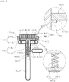
FIG. 3 is an enlarged view illustrating a state in which an internal microneedle protrudes when the contact plate illustrated inFIG. 2 is pressed. -
FIG. 4 is a view illustrating an internal state of a main body portion illustrated inFIG. 1 . -
FIG. 5 is a view illustrating a state in which a pressure button is pressed when a contact plate slides. - Hereinafter, preferred embodiments according to the present invention will be described in detail with reference to the accompanying drawings. Terms or words used in the present specification and claims should not be construed as being limited to their ordinary or dictionary meanings and should be interpreted with meanings and concepts consistent with the technical idea of the present invention, based on the principle that inventors may adequately define concepts of the terms to best describe their invention.
- Referring to
FIGS. 1 to 5 , amicroneedle stamp device 1000 for injecting liquid medicine, according to an embodiment of the present invention may include amain body portion 1100, acarboxy cartridge 1200, a liquidmedicine storage portion 1300, aneedle portion 1400, apower portion 1500, aconnection portion 1600, and acontact plate 1700 and may further include a contactplate support portion 1800. - The
main body portion 1100 includes agrip end 1120 gripped by a clinician and acontact end 1140 that is provided on one side of thegrip end 1120 and is in close contact with the skin of a treatment subject, and it is preferable that thegrip end 1120 has one of a cylindrical shape and a rectangular shape that is easily gripped by a clinician and the inside of thegrip end 1120 is hollow. - Referring to
FIGS. 4 and5 , thecarboxy cartridge 1200 storing carbon dioxide to be injected into a dermis of the skin of a treatment subject together with liquid medicine is provided in themain body portion 1100, and it is preferable that the carbon dioxide to be injected into the dermis of the treatment subject is filled in thecarboxy cartridge 1200. Thecarboxy cartridge 1200 discharges the carbon dioxide filled therein to the outside at a constant pressure and quantity by using pressure provided by thepower portion 1500 described below. The carbon dioxide supplied to the dermis of the treatment subject from thecarboxy cartridge 1200 cuts off fibroblasts in the dermis and activates an increase in oxygen at an injection site. - It is preferable that the
carboxy cartridge 1200 is connected to the liquidmedicine storage portion 1300, and the liquidmedicine storage portion 1300 is provided in the outside of themain body portion 1100, and one end of the liquidmedicine storage portion 1300 is connected to thecarboxy cartridge 1200, and liquid medicine to be injected into the skin of the treatment subject together with carbon dioxide supplied from thecarboxy cartridge 1200 is stored in the liquidmedicine storage portion 1300. - The
carboxy cartridge 1200 and the liquidmedicine storage portion 1300 are connected to theneedle portion 1400, and theneedle portion 1400 injects carbon dioxide and liquid medicine supplied from thecarboxy cartridge 1200 and the liquidmedicine storage portion 1300 into the skin of a treatment subject, preferably into a dermis of the treatment subject. - The
needle portion 1400 includes a plurality ofmicroneedles 1420 and amounting plate 1440 on which the plurality ofmicroneedles 1420 are mounted. One end of each of the plurality ofmicroneedles 1420 is inserted into a dermis of a treatment subject through thecontact plate 1700 described below, and it is preferable that flow paths through which liquid medicine and carbon dioxide flow are formed in the plurality ofmicroneedles 1420 to penetrate the plurality ofmicroneedles 1420. - The other end of each of the plurality of
microneedles 1420 is mounted on themounting plate 1440, and themounting plate 1440 is provided with aconnection end 1440a connected to theconnection portion 1600 described below, and theconnection end 1440a is preferably provided at a position corresponding to the plurality ofmicroneedles 1420. - A
flow path 1440b through which liquid medicine and carbon dioxide supplied through theconnection portion 1600 and theconnection end 1440a described below flow is formed in themounting plate 1440, and theflow path 1440b is preferably communicate with the flow paths penetrating themicroneedles 1420. As theflow path 1440b communicates with the flow paths penetrating themicroneedles 1420, liquid medicine and carbon dioxide supplied to theflow path 1440b are directly injected into a dermis of a treatment subject through themicroneedles 1420. - The plurality of
microneedles 1420 have thicknesses of 0.25 mm to 0.8 mm, and preferably lengths of 0.2 mm to 3 mm. Because themicroneedles 1420 have the thicknesses of 0.25 mm to 0.8 mm, small dot-shaped through-holes may be formed in the skin of a treatment subject, and thus, it is possible to prevent contaminants from entering the skin through the through-holes, and because the microneedles have lengths of 0.2 mm to 3 mm, it is possible to prevent contaminants from being injected beyond a dermal layer of the treatment subject. - The
carboxy cartridge 1200 is connected to theneedle portion 1400 by theconnection portion 1600, and thepower portion 1500 for providing pressure to thecarboxy cartridge 1200 is provided around aconnection end 1210 that protrudes from a front end of thecarboxy cartridge 1200 and is connected to theconnection portion 1600 described below. - The
carboxy cartridge 1200 provided in thegrip end 1120 is connected to theconnection portion 1600 through thepower portion 1500, and thecarboxy cartridge 1200 is fixed to the inside of thegrip end 1120 by using a separate fixed member so as not to move. - The
power portion 1500 applies pressure to thecarboxy cartridge 1200 and the liquidmedicine storage portion 1300 while being operated by an external force applied from the outside, and the liquid medicine and carbon dioxide filled in thecarboxy cartridge 1200 and the liquidmedicine storage portion 1300 are supplied to theneedle portion 1400 through theconnection portion 1600 while being discharged to the outside thereof by the pressure supplied from thepower portion 1500. - Referring to
FIGS. 1 ,2 ,4 , and5 , thepower portion 1500 includes apressure button 1520 that operates thepower portion 1500 and is exposed to the outside, and thepower portion 1500 operates when thepressure button 1520 is pressed while thecontact plate 1700 described below slidingly moves. Thepower portion 1500 is preferably formed with aconnection hole 1500a through which a connection conduit 1320 protruding from one side of the liquidmedicine storage portion 1300 passes to be connected to theconnection end 1210 of thecarboxy cartridge 1200. - the
contact plate 1700 is provided on thecontact end 1140 of themain body portion 1100 and is exposed to the outside of thecontact end 1140. Thecontact plate 1700 includes acontact member 1720 having a plurality of through-holes 1720a through which theneedle portion 1400 passes, and apressure member 1740 that protrudes from one side of thecontact member 1720 and presses thepressure button 1520 when thecontact plate 1700 slidingly moves. - The
pressure member 1740 presses thepressure button 1520 while passing through a through-hole 1140a formed in the inside of thecontact end 1140 when thecontact plate 1700 slidingly moves. - Referring to
FIG. 3 , a movementlong groove 1720c on which afixed end 1442 for fixing themounting plate 1440 of theneedle portion 1400 to the inside of thecontact end 1140 is moved is formed on a circumferential surface of thecontact member 1720, and as the fixedend 1442 provided on an outer surface of themounting plate 1440 is moved on the movementlong groove 1720c, thecontact plate 1700 is slidingly moved in thecontact end 1140. - Referring to
FIGS. 4 and5 , a contactplate support portion 1800 for elastically supporting thecontact plate 1700 is provided in themain body portion 1100, and the contactplate support portion 1800 is preferably provided in thecontact end 1140 of the main body portion1100. - The contact
plate support portion 1800 includes aprotrusion 1820 and aspring member 1840. Theprotrusion 1820 is provided in thecontact end 1140 and protrudes inward from an inner circumferential surface of thecontact end 1140. Thespring member 1840 is provided in thecontact end 1140 and has one end in close contact with an inner surface of thecontact end 1140 and the other end in close contact with thecontact plate 1700, and thus, thespring member 1840 elastically supports thecontact plate 1700. Theprotrusion 1820 is located inside thespring member 1820 to fix a position of thespring member 1820. - A
guide protrusion 1720b that limits a protrusion range of thecontact plate 1700 protruding to the outside of thecontact end 1140 is preferably provided on a circumferential surface of thecontact plate 1700 that slidingly moves in thecontact end 1140, and as theguide protrusion 1720b is caught on thecontact end 1140, a range in which thecontact plate 1700 is exposed to the outside of thecontact end 1140 is limited. - Therefore, when a clinician grips the
grip end 1120 and then thecontact end 1140 comes into contact with the skin of the treatment subject, thecontact plate 1700 is pushed to insert the plurality ofmicroneedles 1420 into a dermis of the treatment subject such that liquid medicine and carbon dioxide may be directly injected into the dermal layer of the treatment subject without forming a linear long hole, and thus, it is possible to easily inject a certain amount of liquid medicine and carbon dioxide into the dermal layer of the treatment subject at a constant pressure by using a simple physical force without using a complex electronic device. - Although the present invention is described with reference to the embodiment illustrated in the drawings, which is a merely example, and those skilled in the art will understand that various modifications and equivalent other embodiments are possible therefrom. Therefore, the true technical protection scope of the present invention should be determined by the technical idea of the appended claims.
- The present invention may be used in a device for injecting liquid medicine.
Claims (7)
- A microneedle stamp device for injecting liquid medicine, the micro stamp device comprising:a main body portion including a grip end gripped by a clinician and a contact end to come into contact with a skin of a treatment subject;a carboxy cartridge provided in the main body portion and storing carbon dioxide to be injected into the skin of the treatment subject;a liquid medicine storage portion provided outside the main body portion and connected to the carboxy cartridge and storing the liquid medicine to be injected into the skin of the treatment subject together with the carbon dioxide supplied from the carboxy cartridge;a needle portion connected to the carboxy cartridge and the liquid medicine storage portion and configured to inject the carbon dioxide and the liquid medicine supplied from the carboxy cartridge and the liquid medicine storage portion into the skin of the treatment subject;a power portion provided in the grip end and configured to be operated by an external force applied from an outside to provide pressure to the carboxy cartridge and the liquid medicine storage portion such that the carbon dioxide stored in the carboxy cartridge and the liquid medicine stored in the liquid medicine storage portion is supplied to the needle portion;a connection portion configured to connect the carboxy cartridge to the needle portion; anda contact plate provided at the contact end of the main body portion and protruding to an outside of the contact end and including the needle portion therein and including a plurality of through-holes through which the needle portion passes and configured to slidingly move to the inside of the contact end when coming into contact with the skin of the treatment subject,wherein, when the contact plate comes into contact with the skin of the treatment subject, the contact plate slidingly moves to the inside of the contact end to apply an external force to the power portion to operate the power portion to supply the liquid medicine and the carbon dioxide to the needle portion.
- The micro stamp device of claim 1, further comprising:a contact plate support portion provided in the main body portion to elastically support the contact plate,wherein the contact plate support portion includes a protrusion provided in an inner side of the contact end and protruding inward from an inner surface of the contact end, and a spring member provided in the contact end and having one end in contact with the inner surface of the contact end and the other end in contact with the contact plate,wherein the protrusion is located inside the spring member, andwherein a guide protrusion is provided on a circumferential surface of the contact plate to guide a protrusion range of the contact plate protruding to an outside of the contact plate.
- The micro stamp device of claim 2, whereina pressure button for operating the power portion is exposed to an outside of the power portion, andwhen the contact plate slidingly moves, the contact plate presses the pressure button to operate the power portion, andthe power portion is formed with a connection hole through which one end of the liquid medicine storage portion passes to be connected to the carboxy cartridge.
- The micro stamp device of claim 3, wherein the adhesive plate comprises:a contact member having a plurality of through-holes through which the needle portion passes; anda pressure member protruding to one side of the contact member and configured to press the pressure button while passing through a through-hole formed in the contact end when the contact plate slidingly moves.
- The micro stamp device of claim 4, whereinthe needle portion includes a plurality of microneedles each having one end passing through the plurality of through-holes, and a mounting plate having one side on which the other end of each of the plurality of microneedles is mounted and the other side on which a connection end connected to the connection portion is provided,a flow path through which the liquid medicine supplied through the connection portion and the connection end flows is formed in the mounting plate, andthe liquid medicine is supplied to the plurality of microneedles through the flow path.
- The micro stamp device of claim 5, whereina fixed end for fixing the mounting plate to an inside of the contact end is provided on an outer surface of the mounting plate, anda movement long hole through which the fixed end is moved is formed in the contact member.
- The micro stamp device of claim 5, wherein the plurality of microneedles have thickness of 0.25 mm to 0.8 mm and have lengths of 0.2 mm to 3 mm.
Applications Claiming Priority (2)
| Application Number | Priority Date | Filing Date | Title |
|---|---|---|---|
| KR1020190095597A KR102214553B1 (en) | 2019-08-06 | 2019-08-06 | Micro needle stamping machine for chemical solution injection |
| PCT/KR2020/010400 WO2021025484A1 (en) | 2019-08-06 | 2020-08-06 | Microneedle stamp device for injecting liquid medicine |
Publications (2)
| Publication Number | Publication Date |
|---|---|
| EP4011433A1 true EP4011433A1 (en) | 2022-06-15 |
| EP4011433A4 EP4011433A4 (en) | 2023-10-11 |
Family
ID=74502777
Family Applications (1)
| Application Number | Title | Priority Date | Filing Date |
|---|---|---|---|
| EP20850992.7A Withdrawn EP4011433A4 (en) | 2019-08-06 | 2020-08-06 | Microneedle stamp device for injecting liquid medicine |
Country Status (4)
| Country | Link |
|---|---|
| US (1) | US12318565B2 (en) |
| EP (1) | EP4011433A4 (en) |
| KR (1) | KR102214553B1 (en) |
| WO (1) | WO2021025484A1 (en) |
Families Citing this family (3)
| Publication number | Priority date | Publication date | Assignee | Title |
|---|---|---|---|---|
| WO2021228856A1 (en) * | 2020-05-11 | 2021-11-18 | Evjensvold Laila Rigmor | Injection device with multiple cannulas |
| DE102024200346A1 (en) * | 2024-01-15 | 2025-07-17 | Volkswagen Aktiengesellschaft | Method and process arrangement for manufacturing an electrode for a lithium-ion battery cell |
| US20250295216A1 (en) * | 2024-03-22 | 2025-09-25 | Elc Management Llc | Temperature Controlled Applicator For Cosmetic Product |
Family Cites Families (18)
| Publication number | Priority date | Publication date | Assignee | Title |
|---|---|---|---|---|
| US6905489B2 (en) * | 2001-04-24 | 2005-06-14 | Northgate Technologies, Inc. | Laparoscopic insertion device |
| WO2008095124A1 (en) * | 2007-01-31 | 2008-08-07 | Somark Innovations, Inc. | Device and method for providing a readable mark |
| KR100921009B1 (en) | 2007-05-14 | 2009-10-23 | 주식회사 제이앤엘 | Micro Needle Roller Structure |
| KR20110013796A (en) * | 2009-08-03 | 2011-02-10 | 진세훈 | Multi needle for dermal regeneration |
| KR101180113B1 (en) * | 2010-10-18 | 2012-09-06 | (주)엠큐어 | Apparatus able to inject gas and drug into skin sequentially |
| KR101299231B1 (en) * | 2012-02-16 | 2013-08-22 | (주)메가메디칼 | Complex apparatus for body form care and weight clinic |
| KR101575039B1 (en) * | 2012-07-19 | 2015-12-07 | (주)아모레퍼시픽 | Nozzle device and minimal invasive injection device comprising the same |
| EP2968739B1 (en) * | 2013-03-13 | 2020-04-22 | Incube Labs, Llc | Infusion systems for the controlled delivery of therapeutic agents |
| EP2968885A4 (en) * | 2013-03-15 | 2017-03-01 | Plum Systems Co. | Apparatus and method for tissue rejuvenation |
| KR101740950B1 (en) * | 2015-02-17 | 2017-06-15 | 주식회사 은성글로벌 | Skin therapy apparatus with needle |
| KR101675333B1 (en) * | 2015-03-31 | 2016-11-11 | 주식회사 현대메디텍 | Meso gun provided carbon dioxide |
| KR101653266B1 (en) * | 2015-07-23 | 2016-09-01 | (주)엠큐어 | Portable Infusing Device for Medicine |
| KR101608179B1 (en) | 2015-11-24 | 2016-03-31 | 지승구 | Device for injecting drug into skin |
| KR101739898B1 (en) * | 2016-05-26 | 2017-05-24 | 고대철 | Carbon dioxide gas injection apparatus |
| KR20160110319A (en) * | 2016-09-02 | 2016-09-21 | (주)휴러스트 | Combinational surgical procedure device capable of carbone dioxide/drug injection alternatively |
| KR101759272B1 (en) | 2016-11-08 | 2017-07-19 | 진세훈 | Syringe for selective self dermal rejuvenation |
| KR101903682B1 (en) * | 2017-01-06 | 2018-10-05 | (주)엠큐어 | Injector of Gas and Drug |
| US20180264043A1 (en) * | 2017-03-14 | 2018-09-20 | Holding Pen, Llc | Restoration of deteriorated tissue in the face or selected areas of the body with mesenchymal stem cells |
-
2019
- 2019-08-06 KR KR1020190095597A patent/KR102214553B1/en active Active
-
2020
- 2020-08-06 EP EP20850992.7A patent/EP4011433A4/en not_active Withdrawn
- 2020-08-06 WO PCT/KR2020/010400 patent/WO2021025484A1/en not_active Ceased
- 2020-08-06 US US17/633,426 patent/US12318565B2/en active Active
Also Published As
| Publication number | Publication date |
|---|---|
| WO2021025484A1 (en) | 2021-02-11 |
| KR102214553B1 (en) | 2021-02-09 |
| US12318565B2 (en) | 2025-06-03 |
| US20220280764A1 (en) | 2022-09-08 |
| EP4011433A4 (en) | 2023-10-11 |
Similar Documents
| Publication | Publication Date | Title |
|---|---|---|
| US12318565B2 (en) | Microneedle stamp device for injecting liquid medicine | |
| KR101608179B1 (en) | Device for injecting drug into skin | |
| US20190247637A1 (en) | Multi-site injection system | |
| TWI674910B (en) | Injection device of medical fluid | |
| KR101030752B1 (en) | Micro Needle Units with Adjustable Fluid Delivery | |
| CN102470220B (en) | Injection needle assembly and drug injection device | |
| DE60106261D1 (en) | DELIVERY DEVICE WITH MICRO NEEDLES FOR TRANSDERMAL ADMINISTRATION OF A SUBSTANCE | |
| CN104684610B (en) | Fluid injector operating device using multi-microneedle member | |
| EP1992386A4 (en) | MICROARRAY TRANSDERMAL DRUG DELIVERY APPARATUS | |
| CN102470216A (en) | Injection needle assembly and drug injection device | |
| CN103157178B (en) | Seal type tool capable of accurately controlling microneedle insertion length | |
| US20150025459A1 (en) | Multi-site injection system | |
| WO2005025641A3 (en) | Intradermal injection device | |
| KR100941770B1 (en) | Micro needle roller | |
| KR20110098398A (en) | Injection microneedle stamp | |
| KR101596419B1 (en) | multi needle device for skin beauty and medical treatment with medicine distribution tool | |
| KR102006937B1 (en) | Injection device | |
| KR101386490B1 (en) | Microneedle aray and skin permeation apparatus therewith | |
| KR20180132217A (en) | a device for dosing medicine through the skin | |
| KR20180082756A (en) | inserting apparatus for liquid in human's skin | |
| KR20180002360A (en) | Tip unit for skin washer apparatus and skin washer apparatus including the tip unit | |
| KR20250144279A (en) | Microneedle device and Microneedle system using the same | |
| CN115397502B (en) | Liquid injection device and system and cartridge unit | |
| KR20110083030A (en) | Medical Acupuncture Device | |
| KR20250069471A (en) | Microneedle device and Microneedle system using the same |
Legal Events
| Date | Code | Title | Description |
|---|---|---|---|
| STAA | Information on the status of an ep patent application or granted ep patent |
Free format text: STATUS: THE INTERNATIONAL PUBLICATION HAS BEEN MADE |
|
| PUAI | Public reference made under article 153(3) epc to a published international application that has entered the european phase |
Free format text: ORIGINAL CODE: 0009012 |
|
| STAA | Information on the status of an ep patent application or granted ep patent |
Free format text: STATUS: REQUEST FOR EXAMINATION WAS MADE |
|
| 17P | Request for examination filed |
Effective date: 20220228 |
|
| AK | Designated contracting states |
Kind code of ref document: A1 Designated state(s): AL AT BE BG CH CY CZ DE DK EE ES FI FR GB GR HR HU IE IS IT LI LT LU LV MC MK MT NL NO PL PT RO RS SE SI SK SM TR |
|
| DAV | Request for validation of the european patent (deleted) | ||
| DAX | Request for extension of the european patent (deleted) | ||
| A4 | Supplementary search report drawn up and despatched |
Effective date: 20230913 |
|
| RIC1 | Information provided on ipc code assigned before grant |
Ipc: A61M 5/20 20060101ALI20230907BHEP Ipc: A61M 5/24 20060101ALI20230907BHEP Ipc: A61M 5/32 20060101ALI20230907BHEP Ipc: A61M 37/00 20060101AFI20230907BHEP |
|
| STAA | Information on the status of an ep patent application or granted ep patent |
Free format text: STATUS: THE APPLICATION IS DEEMED TO BE WITHDRAWN |
|
| 18D | Application deemed to be withdrawn |
Effective date: 20240416 |